

SMC Networks HYC Series, HYC 40, HYC 50, HYC 63, HYC 32 Operation Manual
No. HYC*-OM0002I
OPERATION MANUAL
HYGIENIC DESIGN CYLINDER
【HYC Series】
Φ32,Φ40,Φ50,Φ63
☆Read this manual thoroughly before mounting and operating.
☆Pay special attention to the safety instructions.
☆Keep this manual in an easily accessible location.
SMC株式会社
承認・変更来歴表
対応文書名:取扱説明書
対応文書NO:HYC*-OM0002I
コピ-提出不要
変更 日付 変 更 理 由 設変番号 作 成 確 認 承 認
承 認 確 認 確 認 作 成
部署: 開発第2部
作成日: 2005年 3月 2日
本書は、対応文書の原紙と一緒に保管する。
フォーマット No:FSM027-2B

Contents
1.Safety Instructions ・・・・・・・・・・・・・・・・・・・・・・・・・・・・・・・・・・・・・・・・・・・・・・・・・・・・・・・・・・ P1
2.Specifications ・・・・・・・・・・・・・・・・・・・・・・・・・・・・・・・・・・・・・・・・・・・・・・・・・・・・・・・・・・・・・・ P3
2-1.Specifications
3.Installation and Handling ・・・・・・・・・・・・・・・・・・・・・・・・・・・・・・・・・・・・・・・・・・・・・・・・・・・・・・・ P4
3-1.Air supply
3-2.Operating Environment
3-3.Speed adjustment
3-4.Direction control
3-5.Cautions
3-6.Installation, setting-up and other
3-7.Auto switch
4.Model selection ・・・・・・・・・・・・・・・・・・・・・・・・・・・・・・・・・・・・・・・・・・・・・・・・・・・・・・・・・・・・・ P12
4-1.
4-2.
5.Pneumatic circuit ・・・・・・・・・・・・・・・・・・・・・・・・・・・・・・・・・・・・・・・・・・・・・・・・・・・・・・・・・・・・・ P15
6.Maintenance and Checks・・・・・・・・・・・・・・・・・・・・・・・・・・・・・・・・・・・・・・・・・・・・・・・・・・・・・・ P16
6-1.Daily check
6-2.Periodical check
6-3.How to replace packing
6-4.Consumable parts
7.Troubleshooting ・・・・・・・・・・・・・・・・・・・・・・・・・・・・・・・・・・・・・・・・・・・・・・・・・・・・・・・・・・・・・ P23
8.Basic construction ・・・・・・・・・・・・・・・・・・・・・・・・・・・・・・・・・・・・・・・・・・・・・・・・・・・・・・・・・・・ P25
Allowable kinetic energy
Lateral load at rod end
- 1 -
1.Safety Instructions
These safety instructions are intended to prevent hazardous situations and/or equipment damage. These
instructions indicate the level of potential hazard by labels of "Danger ", "Warning" or "Caution ". To ensure
*1)
safety, be sure to observe ISO 4414
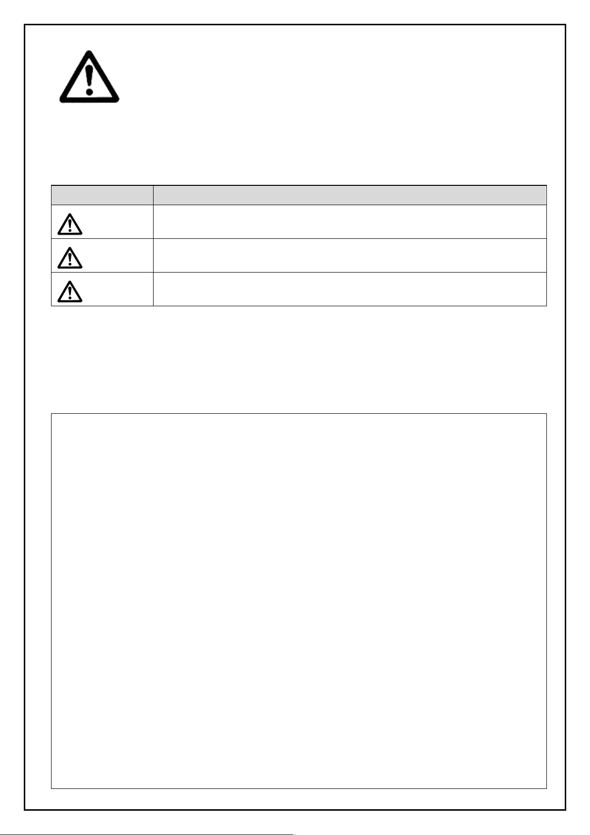
■Indications
Indication Indications
Danger :
Warning :
Caution :
※1) ISO 4414:Pneumatic fluid power – General rules relating to systems
※2) JIS B 8370:General Rules for Pneumatic Equipment
※3) An injury herein, doesn’t mean staying in, or going to the hospital for a long period to recover. This includes
burns and electric shocks..
In extreme conditions, there is a possible result of serious injury or loss of life.
Operator error could result in serious injury or loss of life.
Operator error could result in injury
, JIS B 8370
*2)
and other safety practices.
*3)
or equipment damage
*4)
.
※4) An equipment damage meant herein is an extensive damage related to equipments and machines.
■Selection/Handling/Application
① The compatibility of pneumatic equipment is the responsibility of the person who designs the pneumatic
system or decides its specifications.
Since the products specified here are used in various operating conditions, their compatibility for the specific
pneumatic system must be based on specifications or after analysis and/or tests to meet your specific
requirements. The expected perfomance and safety assurance will be the responsibility of the person who has
determined the compatibility of the system. This person should continuously review the suitability of all items
specified, referring to the latest catalog information with a view to giving due consideration to any possibility of
equipment failure when configuring a system.
② Only trained personnel should operate pneumatically operated machinery and equipment.
Compressed air can be dangerous if an operator is unfamiliar with it. Assembly, handling or repair of pneumatic
systems should be performed by trained and experienced operators.
(A trained and experienced operator is required to have understanding of JIS B 8370 “General Rules for
Pneumatic Equipments” and other safety regulations.)
③ Do not service machinery/equipment or attempt to remove components until safety is confirmed.
1.Inspection and maintenance of machinery/equipment should only be performed once measures to prevent
falling or runaway of the driver objects have been confirmed.
2.When equipment is to be removed, confirm the safety process as mentioned above. Cut the supply
pressure for this equipment, exhaust all residual compressed air in the system and relieve all energy
(liquid pressure, spring force, capacitor, gravity).
3.Before machinery/equipment is restarted, take measures to prevent shooting-out of cylinder piston rod,
etc.
- 2 -

④ Contact SMC if the product is to be used in any of the following conditions:
1.Conditions and environments beyond the given specifications, or if product is used outdoors or place
where direct sunshine strikes.
2.Installation on equipment in conjunction with atomic energy, railway, air navigation, vehicles, medical
equipment, food and beverages, recreation equipment, emergency stop circuits, clutch and brake circuits in
press applications, or safety equipment.
3.An application which has the possibility of having negative effects on people, property, or animals,
requiring special safety analysis.
4.Interlock circuit. In this case, provide double interlock circuit by providing a mechanical protective
function for possible failure of either of them. Also, perform periodical check to ensure it works properly.
■Exemption
①SMC doesn’t take any responsibility for the damage resulting from an earthquake, fire due to other causes
than our products, the third party behavior and the customer’s intentional or unintentional fault, misuse and
operation in other abnormal conditions.
②SMC doesn’t take any responsibility for the damage associated with use of our product or out-of-service
product (including loss of company profits, suspension of company activity).
③SMC doesn’t take any responsibility for the damage resulting from use in a manner other than specified in the
catalogue or Operation Manual and beyond specifications.
④SMC doesn’t take any responsibility for the damage resulting from malfunction due to use of our product in
combination with equipments or software we have no involvement with.
- 3 -
2.Specifications
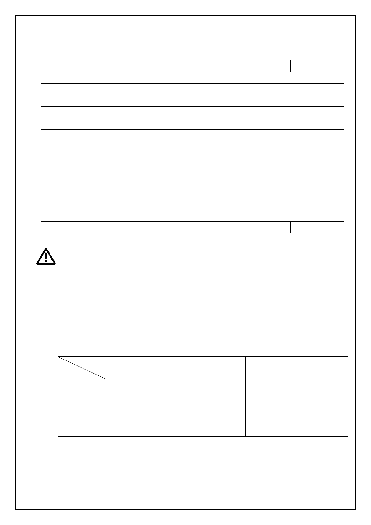
2-1.Specifications
Bore size(mm) 32 40 50 63
Action Double acting , Single rod
Fluid Air
Proof pressure 1.5MPa
Maximum operating pressure 1.0MPa
Minimum operating pressure 0.15MPa
Ambient and fluid temperature
Cushion Air cushion
Lubrication Not required (Non-lube)
Piston speed 50 to 500mm/s (pressurized at 1.0MPa )
Thread tolerance Conforming to ISO 965
Stroke length tolerance
Piston rod material SUS304, hard chrome plated
Port size 1/8(Rc,NPT,G) 1/4(Rc,NPT,G) 3/8(Rc,NPT,G)
Without auto switch:0 to 70℃
With auto switch:0 to 60℃
1.0
+ 1.4
Up to 250mm
251 to 600mm+
0
0
Warning
1) Note the features of the product.
A hygienic design cylinder HYC belongs to a product family developed upon request from overseas country
(Europe) and conforms to ISO standard in its outline and mounting dimensions. Also, different from the
conventional actuator, it is dedicated for machines in food and packaging industries.
The concept of hygienic design is not a cylinder which is sterilized, it is a cylinder with a profile which can
be easily cleaned and kept hygienic.
―Allowable mounting zone―
Food zone The food released to the market is in direct
contact with the cylinder.
Splash zone
(directly)
Non-food zone The food is never in contact with the cylinder. Allowed
※Never set it up in the food zone.
The food might directly contact the cylinder, but
the food isn’t released on the market.
Detail Allowed/Not allowed to mount in
zone
Not allowed
Allowed
2) Confirm the specifications.
The products are designed for use in industrial compressed air systems. If the products are used in
conditions where pressure and/or temperature are outside the range of specifications, damage and/or
malfunctions may occur. Do not use in these conditions. (Refer to the specifications.)
- 4 -
Please consult with SMC if you use a fluid other than compressed air.
3.Installation and Handling
3-1.Air source
The compressed air supplied for the cylinder shall be filtered by air filter, SMC’s AF series and
decreased to given set pressure by regulator, SMC’s AR series for use.
Warning
1) Use clean air.
Do not use compressed air which contains chemicals, synthetic oils containing organic solvents, salts or
corrosive gases, etc., as this can cause damage or malfunction.
Caution
2) Install air filters.
Install air filters close to valves at their upstream side. A filtration degree of 5μm or less should be
selected.
3) Install an aftercooler, air dryer, or water separator (Drain Catch).
Air that includes excessive drainage may cause malfunction of valves and other pneumatic equipment. To
prevent this, install an air dryer, aftercooler or water separator,etc.
4) Use the product within the specified range of fluid and ambient temperature.
Take measures to prevent freezing when below 5℃, since moisture in circuits can freeze and cause
damage to seals and lead to malfunctions.
The allowable operating range for this product is between :
Without auto switch 0 to 70℃
With auto switch 0 to 60℃
If the cylinder is used at temp out of this range, the packing hardens, the grease is lost and the packing is
worn, finally air leaks can result.
For compressed air quality, refer to "Air Preparation Equipment” catalog.
5) Lubrication of cylinder
【Grease for standard(for non-food)】
The cylinder has been lubricated for life at the factory and can be used without any further lubrication.
However, in the event that it is lubricated additionally, be sure to use Class 1 turbine oil (with no additive)
ISO VG32.
Stopping lubrication later may lead to malfunctions because the new lubricant will cancel out the original
lubricant. Therefore, lubrication must be continued once it has been started.
【Grease for food】
The cylinder has been lubricated for life at the factory and can be used without any further lubrication.
If the cylinder is supplied with lubrication, it may fail in operation..
- 5 -
6) Do not wipe off the grease attached on the sliding face of the cylinder.
If the grease is removed from the sliding part of the cylinder forcibly, a malfunction could be caused.
When the cylinder is operated for a long distance, its sliding parts can become blackened. In that case, to
keep the cylinder operating, wipe off the grease from the sliding part once and then add new grease
again. (When the grease is wiped off, use water. If it is wiped off with alcohol or special solvent, the
packing could be damaged.)
7) Before piping
Before piping, it should be thoroughly blown out with air (flushing) or washed to remove chips, cutting oil
and other debris from inside the pipe.
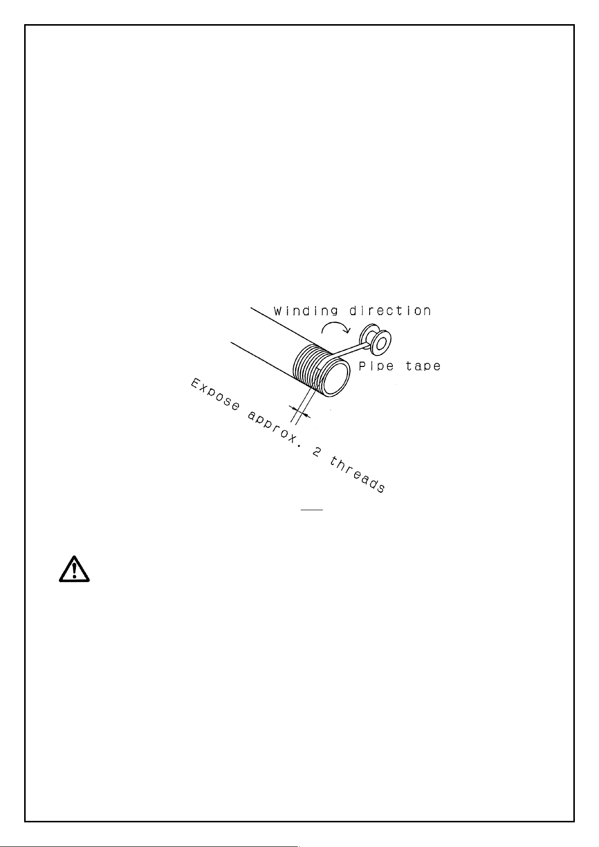
8) Wrapping of pipe tape
When screwing piping or fitting into ports, ensure that chips from the pipe threads or sealing material do
not get inside the piping.
Also, when the pipe tape is used, leave 1.5 to 2 thread ridges exposed at the end of the threads.
Fig 1
3-2.Operating Environment
Warning
1) Do not use in atmosphers or locations where corrosion hazards exist.
Refer to the construction drawings regarding cylinder materials.
2) In dusty locations or where water or oil, etc., splash on the equipment, take suitable
measures to protect the rod.
3) Avoid highly humid places for storage of the cylinder.
When the cylinder is stored, avoid humidity to prevent the occurrence of rust and keep the piston rod
retracted.
4) When using auto switches, do not operate in an environment with strong magnetic fields.
- 6 -
3-3.Speed adjustment
The cylinder can be adjusted to desired speed by SMC’s speed controller, AS series. There are two ways to
do it depending on the port of the cylinder which restricts the supplied air, supply or exhaust port. However,
it should be noted normally the air is restricted at exhaust port.
Caution
1) Use a speed controller to adjust the cylinder drive speed, gradually increasing from a low
speed to the desired speed setting.
2) Perform speed adjustment in the actual operating conditions.
If it is performed under different conditions, it might deviate.
3-4.Direction control
The cylinder can be switched in movement direction by an SMC solenoid valve, which is selected from
various styles for the optimum performance of the cylinder.
Warning
1) Design circuitry to prevent sudden lurching of driven objects.
When a cylinder is driven by an exhaust center type directional control valve or when starting up after
residual pressure is exhausted from the circuit, etc., the piston and its driven object will lurch at high
speed if pressure is applied to one side of the cylinder because of the absence of air pressure inside the
cylinder. Therefore, equipment should be selected and circuits designed to prevent sudden lurching,
because there is a danger of human injury and/or damage to equipment when this occurs.
3-5.Caution on Design
Warning
1) There is a possibility of dangerous sudden action by air cylinders if sliding parts of
machinery are twisted due to external forces, etc.
In such cases, human injury may occur; e.g., by catching hands or feet in the machinery, or damage to the
machinery itself may occur. Therefore, the machine should be adjusted to operate smoothly and designed
to avoid such dangers.
2) A protective cover is recommended to minimize the risk of personal injury.
If a stationary object and moving parts of a cylinder are in close proximity, personal injury may occur.
Design the structure to avoid contact with the human body.
3) Securely tighten all stationary parts and connected parts so that they will not become
loose.
Especially when a cylinder operates with high frequency or is installed where there is a lot of vibration,
ensure that all parts remain secure.
- 7 -
 Loading...