

Page 1
No. HYC*-OM0002I
OPERATION MANUAL
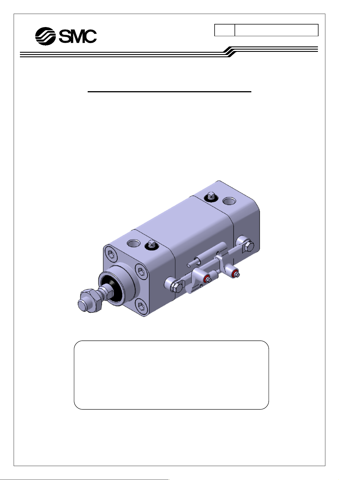
HYGIENIC DESIGN CYLINDER
【HYC Series】
Φ32,Φ40,Φ50,Φ63
☆Read this manual thoroughly before mounting and operating.
☆Pay special attention to the safety instructions.
☆Keep this manual in an easily accessible location.
SMC株式会社
Page 2

承認・変更来歴表
対応文書名:取扱説明書
対応文書NO:HYC*-OM0002I
コピ-提出不要
変更 日付 変 更 理 由 設変番号 作 成 確 認 承 認
承 認 確 認 確 認 作 成
部署: 開発第2部
作成日: 2005年 3月 2日
本書は、対応文書の原紙と一緒に保管する。
フォーマット No:FSM027-2B
Page 3

Contents
1.Safety Instructions ・・・・・・・・・・・・・・・・・・・・・・・・・・・・・・・・・・・・・・・・・・・・・・・・・・・・・・・・・・ P1
2.Specifications ・・・・・・・・・・・・・・・・・・・・・・・・・・・・・・・・・・・・・・・・・・・・・・・・・・・・・・・・・・・・・・ P3
2-1.Specifications
3.Installation and Handling ・・・・・・・・・・・・・・・・・・・・・・・・・・・・・・・・・・・・・・・・・・・・・・・・・・・・・・・ P4
3-1.Air supply
3-2.Operating Environment
3-3.Speed adjustment
3-4.Direction control
3-5.Cautions
3-6.Installation, setting-up and other
3-7.Auto switch
4.Model selection ・・・・・・・・・・・・・・・・・・・・・・・・・・・・・・・・・・・・・・・・・・・・・・・・・・・・・・・・・・・・・ P12
4-1.
4-2.
5.Pneumatic circuit ・・・・・・・・・・・・・・・・・・・・・・・・・・・・・・・・・・・・・・・・・・・・・・・・・・・・・・・・・・・・・ P15
6.Maintenance and Checks・・・・・・・・・・・・・・・・・・・・・・・・・・・・・・・・・・・・・・・・・・・・・・・・・・・・・・ P16
6-1.Daily check
6-2.Periodical check
6-3.How to replace packing
6-4.Consumable parts
7.Troubleshooting ・・・・・・・・・・・・・・・・・・・・・・・・・・・・・・・・・・・・・・・・・・・・・・・・・・・・・・・・・・・・・ P23
8.Basic construction ・・・・・・・・・・・・・・・・・・・・・・・・・・・・・・・・・・・・・・・・・・・・・・・・・・・・・・・・・・・ P25
Allowable kinetic energy
Lateral load at rod end
- 1 -
Page 4
1.Safety Instructions
These safety instructions are intended to prevent hazardous situations and/or equipment damage. These
instructions indicate the level of potential hazard by labels of "Danger ", "Warning" or "Caution ". To ensure
*1)
safety, be sure to observe ISO 4414
■Indications
Indication Indications
Danger :
Warning :
Caution :
※1) ISO 4414:Pneumatic fluid power – General rules relating to systems
※2) JIS B 8370:General Rules for Pneumatic Equipment
※3) An injury herein, doesn’t mean staying in, or going to the hospital for a long period to recover. This includes
burns and electric shocks..
In extreme conditions, there is a possible result of serious injury or loss of life.
Operator error could result in serious injury or loss of life.
Operator error could result in injury
, JIS B 8370
*2)
and other safety practices.
*3)
or equipment damage
*4)
.
※4) An equipment damage meant herein is an extensive damage related to equipments and machines.
■Selection/Handling/Application
① The compatibility of pneumatic equipment is the responsibility of the person who designs the pneumatic
system or decides its specifications.
Since the products specified here are used in various operating conditions, their compatibility for the specific
pneumatic system must be based on specifications or after analysis and/or tests to meet your specific
requirements. The expected perfomance and safety assurance will be the responsibility of the person who has
determined the compatibility of the system. This person should continuously review the suitability of all items
specified, referring to the latest catalog information with a view to giving due consideration to any possibility of
equipment failure when configuring a system.
② Only trained personnel should operate pneumatically operated machinery and equipment.
Compressed air can be dangerous if an operator is unfamiliar with it. Assembly, handling or repair of pneumatic
systems should be performed by trained and experienced operators.
(A trained and experienced operator is required to have understanding of JIS B 8370 “General Rules for
Pneumatic Equipments” and other safety regulations.)
③ Do not service machinery/equipment or attempt to remove components until safety is confirmed.
1.Inspection and maintenance of machinery/equipment should only be performed once measures to prevent
falling or runaway of the driver objects have been confirmed.
2.When equipment is to be removed, confirm the safety process as mentioned above. Cut the supply
pressure for this equipment, exhaust all residual compressed air in the system and relieve all energy
(liquid pressure, spring force, capacitor, gravity).
3.Before machinery/equipment is restarted, take measures to prevent shooting-out of cylinder piston rod,
etc.
- 2 -
Page 5

④ Contact SMC if the product is to be used in any of the following conditions:
1.Conditions and environments beyond the given specifications, or if product is used outdoors or place
where direct sunshine strikes.
2.Installation on equipment in conjunction with atomic energy, railway, air navigation, vehicles, medical
equipment, food and beverages, recreation equipment, emergency stop circuits, clutch and brake circuits in
press applications, or safety equipment.
3.An application which has the possibility of having negative effects on people, property, or animals,
requiring special safety analysis.
4.Interlock circuit. In this case, provide double interlock circuit by providing a mechanical protective
function for possible failure of either of them. Also, perform periodical check to ensure it works properly.
■Exemption
①SMC doesn’t take any responsibility for the damage resulting from an earthquake, fire due to other causes
than our products, the third party behavior and the customer’s intentional or unintentional fault, misuse and
operation in other abnormal conditions.
②SMC doesn’t take any responsibility for the damage associated with use of our product or out-of-service
product (including loss of company profits, suspension of company activity).
③SMC doesn’t take any responsibility for the damage resulting from use in a manner other than specified in the
catalogue or Operation Manual and beyond specifications.
④SMC doesn’t take any responsibility for the damage resulting from malfunction due to use of our product in
combination with equipments or software we have no involvement with.
- 3 -
Page 6
2.Specifications
2-1.Specifications
Bore size(mm) 32 40 50 63
Action Double acting , Single rod
Fluid Air
Proof pressure 1.5MPa
Maximum operating pressure 1.0MPa
Minimum operating pressure 0.15MPa
Ambient and fluid temperature
Cushion Air cushion
Lubrication Not required (Non-lube)
Piston speed 50 to 500mm/s (pressurized at 1.0MPa )
Thread tolerance Conforming to ISO 965
Stroke length tolerance
Piston rod material SUS304, hard chrome plated
Port size 1/8(Rc,NPT,G) 1/4(Rc,NPT,G) 3/8(Rc,NPT,G)
Without auto switch:0 to 70℃
With auto switch:0 to 60℃
1.0
+ 1.4
Up to 250mm
251 to 600mm+
0
0
Warning
1) Note the features of the product.
A hygienic design cylinder HYC belongs to a product family developed upon request from overseas country
(Europe) and conforms to ISO standard in its outline and mounting dimensions. Also, different from the
conventional actuator, it is dedicated for machines in food and packaging industries.
The concept of hygienic design is not a cylinder which is sterilized, it is a cylinder with a profile which can
be easily cleaned and kept hygienic.
―Allowable mounting zone―
Food zone The food released to the market is in direct
contact with the cylinder.
Splash zone
(directly)
Non-food zone The food is never in contact with the cylinder. Allowed
※Never set it up in the food zone.
The food might directly contact the cylinder, but
the food isn’t released on the market.
Detail Allowed/Not allowed to mount in
zone
Not allowed
Allowed
2) Confirm the specifications.
The products are designed for use in industrial compressed air systems. If the products are used in
conditions where pressure and/or temperature are outside the range of specifications, damage and/or
malfunctions may occur. Do not use in these conditions. (Refer to the specifications.)
- 4 -
Page 7
Please consult with SMC if you use a fluid other than compressed air.
3.Installation and Handling
3-1.Air source
The compressed air supplied for the cylinder shall be filtered by air filter, SMC’s AF series and
decreased to given set pressure by regulator, SMC’s AR series for use.
Warning
1) Use clean air.
Do not use compressed air which contains chemicals, synthetic oils containing organic solvents, salts or
corrosive gases, etc., as this can cause damage or malfunction.
Caution
2) Install air filters.
Install air filters close to valves at their upstream side. A filtration degree of 5μm or less should be
selected.
3) Install an aftercooler, air dryer, or water separator (Drain Catch).
Air that includes excessive drainage may cause malfunction of valves and other pneumatic equipment. To
prevent this, install an air dryer, aftercooler or water separator,etc.
4) Use the product within the specified range of fluid and ambient temperature.
Take measures to prevent freezing when below 5℃, since moisture in circuits can freeze and cause
damage to seals and lead to malfunctions.
The allowable operating range for this product is between :
Without auto switch 0 to 70℃
With auto switch 0 to 60℃
If the cylinder is used at temp out of this range, the packing hardens, the grease is lost and the packing is
worn, finally air leaks can result.
For compressed air quality, refer to "Air Preparation Equipment” catalog.
5) Lubrication of cylinder
【Grease for standard(for non-food)】
The cylinder has been lubricated for life at the factory and can be used without any further lubrication.
However, in the event that it is lubricated additionally, be sure to use Class 1 turbine oil (with no additive)
ISO VG32.
Stopping lubrication later may lead to malfunctions because the new lubricant will cancel out the original
lubricant. Therefore, lubrication must be continued once it has been started.
【Grease for food】
The cylinder has been lubricated for life at the factory and can be used without any further lubrication.
If the cylinder is supplied with lubrication, it may fail in operation..
- 5 -
Page 8
6) Do not wipe off the grease attached on the sliding face of the cylinder.
If the grease is removed from the sliding part of the cylinder forcibly, a malfunction could be caused.
When the cylinder is operated for a long distance, its sliding parts can become blackened. In that case, to
keep the cylinder operating, wipe off the grease from the sliding part once and then add new grease
again. (When the grease is wiped off, use water. If it is wiped off with alcohol or special solvent, the
packing could be damaged.)
7) Before piping
Before piping, it should be thoroughly blown out with air (flushing) or washed to remove chips, cutting oil
and other debris from inside the pipe.
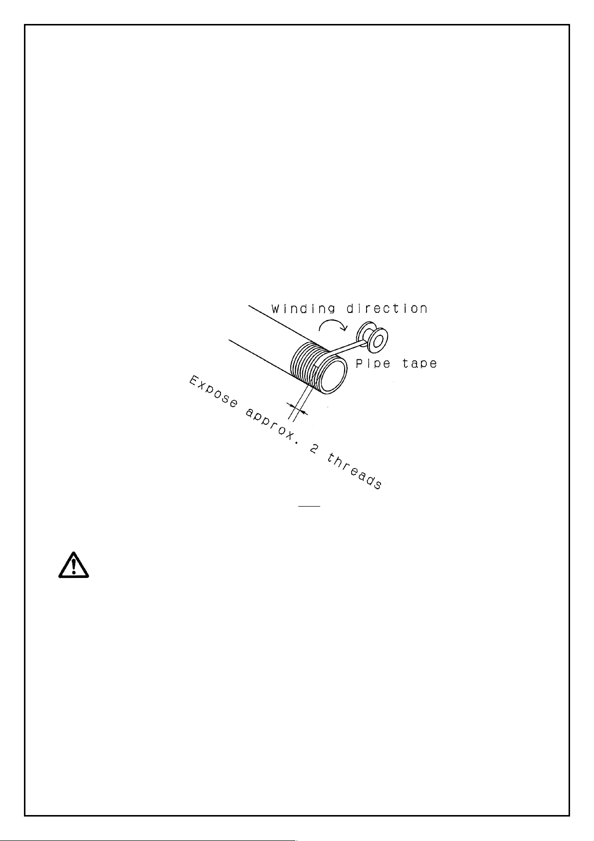
8) Wrapping of pipe tape
When screwing piping or fitting into ports, ensure that chips from the pipe threads or sealing material do
not get inside the piping.
Also, when the pipe tape is used, leave 1.5 to 2 thread ridges exposed at the end of the threads.
Fig 1
3-2.Operating Environment
Warning
1) Do not use in atmosphers or locations where corrosion hazards exist.
Refer to the construction drawings regarding cylinder materials.
2) In dusty locations or where water or oil, etc., splash on the equipment, take suitable
measures to protect the rod.
3) Avoid highly humid places for storage of the cylinder.
When the cylinder is stored, avoid humidity to prevent the occurrence of rust and keep the piston rod
retracted.
4) When using auto switches, do not operate in an environment with strong magnetic fields.
- 6 -
Page 9
3-3.Speed adjustment
The cylinder can be adjusted to desired speed by SMC’s speed controller, AS series. There are two ways to
do it depending on the port of the cylinder which restricts the supplied air, supply or exhaust port. However,
it should be noted normally the air is restricted at exhaust port.
Caution
1) Use a speed controller to adjust the cylinder drive speed, gradually increasing from a low
speed to the desired speed setting.
2) Perform speed adjustment in the actual operating conditions.
If it is performed under different conditions, it might deviate.
3-4.Direction control
The cylinder can be switched in movement direction by an SMC solenoid valve, which is selected from
various styles for the optimum performance of the cylinder.
Warning
1) Design circuitry to prevent sudden lurching of driven objects.
When a cylinder is driven by an exhaust center type directional control valve or when starting up after
residual pressure is exhausted from the circuit, etc., the piston and its driven object will lurch at high
speed if pressure is applied to one side of the cylinder because of the absence of air pressure inside the
cylinder. Therefore, equipment should be selected and circuits designed to prevent sudden lurching,
because there is a danger of human injury and/or damage to equipment when this occurs.
3-5.Caution on Design
Warning
1) There is a possibility of dangerous sudden action by air cylinders if sliding parts of
machinery are twisted due to external forces, etc.
In such cases, human injury may occur; e.g., by catching hands or feet in the machinery, or damage to the
machinery itself may occur. Therefore, the machine should be adjusted to operate smoothly and designed
to avoid such dangers.
2) A protective cover is recommended to minimize the risk of personal injury.
If a stationary object and moving parts of a cylinder are in close proximity, personal injury may occur.
Design the structure to avoid contact with the human body.
3) Securely tighten all stationary parts and connected parts so that they will not become
loose.
Especially when a cylinder operates with high frequency or is installed where there is a lot of vibration,
ensure that all parts remain secure.
- 7 -
Page 10

4) A deceleration circuit or shock absorber may be required.
When a driven object is operated at high speed or the load is heavy, a cylinder’s cushion will not be
sufficient to absorb the impact. Install a deceleration circuit to reduce the speed before cushioning, or
install an eternal shock absorber to relieve the impact.
In this case, the rigidity of the machinery should also be examined.
5) Consider a possible drop in circuit pressure due to a power outage, etc.
When a cylinder is used in a clamping mechanism, there is a danger of workpieces dropping if there is a
decrease in clamping force due to a drop in circuit pressure caused by a power outage, etc. Therefore,
safety equipment should be installed to prevent damage to machinery and human injury. Suspension
mechanisms and lifting devices also require consideration for drop prevention.
6) Consider a possible loss of power source.
Measures should be taken to protect against bodily injury and equipment damage in the event that there
is a loss of power to equipment conrtolled by pneumatics, electricity, or hydraulics.
7) Consider emergency stops.
Design so that human injury and/or damage to machinery and euqipment will not be caused when
machinery is stopped by a safety device under abnormal conditions, a power outage or a manual
emergency stop.
8) Consider the action when operation is restarted after an emergency stop or abnormal stop.
Design the machinery so that human injury or equipment damage will not occur upon restart of operation.
When the cylinder has to be reset at the starting position, install manual safely equipment.
9) Design the system not to allow external force over max. output of the cylinder.
Excessive external force may break the cylinder and lead to human injury and equipment damage.
10) Consider the force output by the cylinder to check the adequacy of mounting base in
rigidity.
If the mounting base is not rigid enough, the human injury and equipment damage may be caused.
11) Do not operate multiple cylinders simultaneously.
An air is compressive fluid and difficult to control in its speed. The change in supply pressure, load,
temperature, lubrication and deviation and change over the time of performance of the cylinder could
affect the speed. Therefore, the simultaneous operation of the cylinders are possible for short period by
adjusting with a speed controller, but these factors may easily break the simultaneous operation. If it
breaks, an excessive force is given to the piston rod due to difference in the positions. The force
becomes a lateral load and causes eccentric wear of the packing, wear of the bushing and damage
between the cylinder tube and piston. For this reason, the design to depend on the simultaneous
operation of the cylinders should be avoided. If it is compelled, use a rigid and high accurate guide to
compensate the force outputted by each cylinder.
12) About intermediate stop
In the case of a 3 position closed center valve, it is difficult to make a piston stop at the required position
as acurately and precisely as with hydraulic pressure, due to compressibility of air.
Furthermore, since valves and cylinders, etc. are not guaranteed for zero air leakage, it may not be
possible to hold a stopped position for an extended period of time. Please contact SMC in the case it is
necessary to hold stopped position for extended period.
- 8 -
Page 11

Caution
13) Operate the piston within a range such that collision damage will not occre at the stroke
end.
The operation range should prevent damage from occurring when a piston, having inertial force, stops by
striking the cover at the stroke end. Refer to the cylinder model selection procedure for the maximum
usable stroke.
3-6.Installation, Setting-up and Other
Caution
1) Be certain to match the rod shaft center with the load and direction of movement when
connecting.
When not properly matched, problems may arise with the rod and tube, and damage may be caused due
to friction on areas such as the inner tube surface, bushings, rod surface, and seals.
2) When an external guide is used, connect the rod end and the load in such a way that there
is no interference at any point within the stroke.
3) Do not scratch or dent the sliding portion of the cylinder tube or the piston rod by striking
it with an object, or squeezing it.
The tube bore is manufactured under precise tolerances. Thus, even a slight deformation could lead to a
malfunction.
Moreover, scratches or gouges, etc. in the piston rod may lead to damaged seals and cause air leakage.
4) Do not use until you verify that the equipment can operate properly.
After mounting, repairs, or modification, etc., connect the air supply and electric power, and then confirm
proper mounting by means of appropriate function and leak tests.
5) Prevent the rotating parts from seizing.
After mounting, repair or modification, etc., connect the air supply and electric power, and then confirm
proper mounting by means of appropriate function and leak inspections.
6) Be sure to hold spanner flat of the piston rod when mounting and removing the load.
If the piston rod at load side is not held, the connected (threaded) part of the piston rod could be
loosened.
- 9 -
Page 12

7) Shorten the piping length.
If piping, too long is connected, the volume of the piping becomes larger than that of the cylinder, and the
mist created by adiabatic swelling is prevented from escaping to the air and remains inside the tube. As
the operation is repeated, the amount of mist is increased and may turn into water. Then, the grease is
washed away by the water and a lack of lubrication, wear of packing, air leakage, friction resistance
increase and operating failure is caused subsequently. To prevent this, the following measure should be
taken.
(1)Shorten the piping tube between solenoid valve and cylinder as much as possible to ensure the
created mist is exhausted to the air. For reference, the following relation should be achieved.
Cylinder content volume at atmospheric pressure×0.7≧Piping tube content volume
(2)Connect speed exhaust controller ASV and quick exhaust valve in the circuit of the cylinder to
exhaust the pressure to atmosphere directly.
(3)Locate the piping port downward to prevent the moisture created in the piping from returning to the
cylinder easily.
8) Give consideration not to splash chemical, which could wash away oil, on the sliding part of
the cylinder.
Some chemicals could wash away the grease from the sliding part of the piston rod. Any chemical other
than general cleaning fluid for water and food could shorten the life significantly. Consult SMC if it is
used.
9) Mount the cylinder, support bracket and plug bolt with the following specific tightening
torque.
Table 1
Applicable bore size Thread size Tightening torque(N・m)
Φ32・40 M6×1 4.22~7.60
Φ50・63 M8×1.25 10.20~18.40
Fig 2
10) The mounting screw and bracket for the cylinder might let the dust collected in some
operating conditions.
Take a measure depending on the operating conditions when mounting.
- 10 -
Page 13

3-7.Auto switch
The type and specifications of applicable auto switch and the cautions for handling of them can be found on
the catalog and operation manual respectively.
3-7-1.Mounting position for detection at stroke end and Operating Range
Table 2 Unit:mm
Applicable bore size A B Operating Range
Φ32 7.5 16.5
Φ40 12 23
Φ50 9 19
Φ63 19 24
Fig 3
7.5
3-7-2.How to mount auto switch
①Insert the rail into the mounting groove. Loosen the mounting screw in advance.
②Decide the position and tighten the screw.
Tightening torque:0.8~1.4N・m
Mounting screw
Auto switch
Fig 4
- 11 -
Switch rail
Page 14

3-7-3.Minimum Strokes for Auto Switch Mounting
Table 3
No. of auto swithes
1 5
2 10
D-F6□
- 12 -
Page 15

4.Model selection
4-1.Allowable Kinetic Energy
Table 4
Bore size(mm) 32 40 50 63
Piston speed(m/s) 0.05~0.5
Allowable kinetic energy(J) 2.2 3.4 5.9 11
【Formula】
W
Load weight:M
Weight of cylinder
operating part:m
2
+
M)V(m
Kinetic energy E(J)=
m:Weight of cylinder operating part(kg)
2
M:Load weight(kg)
V:Piston speed(m/s)
Weight of cylinder movable parts / Without built-in magnet Unit:kg
Bore
size
(mm)
32 0.20 0.23 0.25 0.27 0.29 0.32 0.36 0.41 0.45 0.54 0.63 ―
40 0.37 0.41 0.45 0.49 0.53 0.57 0.65 0.73 0.81 0.97 1.13 ―
50 0.63 0.69 0.75 0.82 0.88 0.94 1.07 1.19 1.31 1.56 1.81 2.06
63 0.84 0.90 0.96 1.02 1.08 1.15 1.27 1.40 1.52 1.77 2.02 2.27
Weight of cylinder movable parts / With built-in magnet Unit:kg
25 50 75 100 125 150 200 250 300 400 500 600
Cylinder stroke(mm)
Bore
size
(mm)
32 0.21 0.24 0.26 0.28 0.30 0.33 0.37 0.42 0.46 0.55 0.64 ―
40 0.38 0.42 0.46 0.50 0.54 0.58 0.66 0.74 0.82 0.98 1.14 ―
50 0.64 0.70 0.76 0.83 0.89 0.95 1.08 1.20 1.32 1.57 1.82 2.07
63 0.85 0.91 0.97 1.03 1.09 1.16 1.28 1.41 1.53 1.78 2.03 2.28
25 50 75 100 125 150 200 250 300 400 500 600
Cylinder stroke(mm)
- 13 -
Page 16

4-2.Lateral Load at Rod End
Caution
The load applied on the piston rod shall be kept in axial direction all the time in principle. If it can’t be avoided
to apply the lateral load, keep the lateral load applied on the bushing of the cylinder 1/20 or less of maximum
output of the cylinder.
― Calculation of allowable lateral load ―
F
fB = 、 ・PD
20
π
2
=F F:Maximum output(MPa)
4
fB:Allowable maximum load to bushing(N)
L
< D:Bore size(mm)
fR
1
++
stroke)(LL
21
・fB
P:Maximum operating pressure(MPa)
fR:Allowable mounted load(N)
Fig 5
Table 5
D
(mm)
L
1
(mm)
L2
(mm)
fB
(N)
Stroke range
(mm)
Φ32 64 23 40.2
25,50,75,100,125,150,200,250,300,400,500
Φ40 75.5 26.5 62.8
Φ50 75.5 30.5 98.2
25,50,75,100,125,150,200,250,300,400,500,600
Φ63 90.5 30.5 155.9
※When the load is mounted on the rod end, add the distance to the center of gravity to the dimension L2.
- 14 -
Page 17

50
Φ50,63
45
40
35
Φ40
30
25
20
Φ32
15
Allowable lateral load at rod end (N)
10
5
0
0 100 200 300 400 500 600
Cylinder stroke (mm)
Graph 1
The thick solid line of graph 2 shows the allowable lateral load to the cylinder.
(The distance between the rod end and load is 50mm.)
1) Readjust with the cushion needle.
The cushion is adjusted and almost fully closed at the time of shipment. Therefore, adjust the cushion needle
mounted inside of the cover depending on the load and operating speed before using. When the cushion
needle is rotated clockwise, the restriction becomes smaller and the cushion works stronger.
2) Do not operate the actuator with the cushion needle fully closed.
This could damage the seals.
3) During adjustment of the cushion needle, keep the torque applied on the cushion adjustor
within the following value.
The torque over the following value could damage the adjusting part.
Tightening torque:0.5N・m
4) Do not exceed the cushion needle adjusting range for use.
If the cushion needle is rotated forcibly over its adjusting range, it could be damaged.
Table 6.
Applicable bore size Rotations
Φ32・40 4 rotations or less
Φ50・63 5 rotations or less
- 15 -
Page 18

5.Pneumatic circuit
The typical circuit for HYC series where air filter, regulator, solenoid valve and speed controller (meter-out) are
used for operation is as follows.
Fig 6
- 16 -
Page 19

6.Maintenance and Check
6-1.Daily check
1) Is the operation smooth?
2)There is no abnormal change in piston speed and cycle time?
3)Is there any abnormality in stroke?
6-2.Periodical check
1)Is there any looseness of the cylinder mounting bolt and work?
2)Is the operation smooth?
3)Is there any abnormal change in piston speed and cycle time?
4)Is there any external leakage?
5)Is there any abnormality in stroke?
6)Flaws on the piston rod
7)Is drain of air filter removed periodically?
Check the above-mentioned items, and if any defect is found, take an appropriate measure. If there is unclear
point, consult SMC’s sales.
Warning
1) Perform maintenance in above procedure.
If the cylinder is handled incorrectly, breakage and operating failure of the equipments around the cylinder
may be caused.
2) Removal of equipment and supply and exhaust of compressed air
When the equipment is removed, after confirming the prevention for drop or run away of the work, the
cylinder is taken, cut off air and power supply for the system and exhaust compressed air from the system.
If the system is restarted, confirm the measures to prevent quick extension of the cylinder have been
taken.
6-3.How to replace packing
1.Disassembly of cylinder
①Cleaning of appearance
Wipe off the surface dirt to prevent intrusion of dust and foreign materials during disassembly.
Especially, please note it on the surface of the piston rod.
②Removal of switch rail【if the switch is mounted】
Loosen the hexagon bolt and remove the switch rail and switch rail pedestal .
③Removal of rod cover
Loosen the tie rod nut and remove the rod cover.
④Disassembly
Pull out the piston rod by holding a nut mounted on the piston rod end. At this time, take care not to mark
the internal face of the cylinder tube.
- 17 -
Page 20

⑤Removal of head cover
Loosen the tie rod nut and remove the head cover.
2.Removal of packing
①Rod packing【Fig 7】
Insert a precision screwdriver, from the front of the rod cover and push out. Take care not to mark or
damage the packing groove or rod scraper.
Do not mark or damage
Fig 7
②Cushion packing【Fig 8】
Insert a precision screwdriver etc. from the front of the rod cover and take out. Take care not to mark or
damage the packing groove of the rod cover.
Likewise, insert the precision screwdriver etc. from the front of the head cover and take out. Do not mark
or damage the packing groove of the head cover.
Do not mark or damage
Fig 8
③Piston packing【Fig 9】
Since the piston packing is inserted deeply, push it partially to make it come off and pull it out manually.
Do not use precision screwdriver.
Pick and pull
- 18 -
Page 21

Fig 9
④Tube gasket【Fig 9】
Push the tube gasket partially to make it come off and pull it out manually.
⑤Needle scraper【Fig 10】
Insert a tool with point end into the needle scraper and take out. Take care not to be injured.
Fig 10
3.Application of grease
①Rod packing, Piston packing and Cushion packing【Fig 11,Fig 12,Fig 13】
Apply the grease all around new packing evenly. Also add the grease inside the groove.
grease
Fig 11.Rod packing
②Tube gasket
Spread the grease thinnly over the surface.
③Rod scraper【Fig 14】
Fill the rod scraper groove with the grease.
grease
Fig 12.Piston packing Fig 13.Cushion packing
grease
Fig 14
- 19 -
Page 22

r
④Each components of cylinder【Fig 15】
Cover entirely with grease.
Tape
4.Mounting of packing
①Rod packing【Fig 16】
Note the direction, when mounting the packing.
Then, apply the grease on the packing and bearing evenly.
Sliding part
Width of two
Fig 15
Sliding part
Bearing
grease
Fig 16
≒1mm
②Piston packing
Make sure not to twist the packing, when mounting.
③Cushion packing【Fig 17】
Note the direction when mounting the packing..
Rod side Head side
Fig 17
④Tube gasket
Pay attention not to make the gasket come off.
- 20 -
Page 23

⑤Needle scraper【Fig 18】
Press down with hand to mount. At that time, ensure there is no protrusion from the cover end face.
Fig 18
5.Reassembly of cylinder
①Tighten the head cover.
Wipe off the adhesive from the threaded part of the tie rod bolt and apply adhesive (Loctite 242 (blue) )
newly.
Tighten the cylinder tube and head cover with tie rod bolt.
Table 7 Unit:N・m
Applicable bore size Tightening torque
Φ32
8.8~16.2
Φ40
Φ50
17.2~31.8
Φ63
②Insert the rod assembly into the cylinder tube.
Apply the grease to the part receiving the cylinder tube and insert the rod assembly carefully and slowly, so
as not to damage the piston packing and gasket.
③Tighten the rod cover.
Wipe off the adhesive from the threaded part of the tie rod bolt and apply adhesive (Loctite 242 (blue) )
newly.
Tighten the cylinder tube and rod cover with tie rod bolt. (Tightening torque:refer to table 7)
④Mount the switch rail (if the switch is mounted).
Table 8 Unit:N・m
Applicable bore size Tightening torque
Φ32 to 63 2.2~2.7
⑤Check the assembly condition.
Confirm there is no air leakage from the packing and the cylinder can operate smoothly at minimum
- 21 -
Page 24

operating pressure.
6-4.Consumable parts
6-4-1.Replaced parts
The service parts are as follows.
HYCB□□-PS
Bore size Packing material
Symbol Material
R NBR
H External FKM ※
※External seal including the rod packing, tube gasket and needle
scraper are made of FKM.
Table 9.Seal Kit(Material:NBR)
Content and qty.
Bore size
Kit no.
(mm)
32 HYCB32R-PS 2 1 1 2 2
40 HYCB40R-PS 2 1 1 2 2
50 HYCB50R-PS 2 1 1 2 2
63 HYCB63R-PS 2 1 1 2 2
Table 10.Seal Kit(Material:外部 FKM)
Bore size
Kit no.
(mm)
32 HYCB32H-PS 2 1 1 2 2
40 HYCB40H-PS 2 1 1 2 2
50 HYCB50H-PS 2 1 1 2 2
Cushion
packing
― Material:NBR
Cushion
packing
―
Piston
packing
Piston
packing
Material:
NBR
Rod
packing
Content and qty.
Rod
packing
Tube
gasket
Tube
gasket
Material:FKM
Needle
scraper
Needle
scraper
63 HYCB63H-PS 2 1 1 2 2
6-4-2.Storage of packing (for extended period)
1) Put the packing into enclosed package for storage
2) Avoid exposure to direct sunlight and high temp. and humidity.
Especially, shut off the equipment which possibly causes heat, radiation and ozone from the package.
3) Do not mark or damage the packing by piling up large amount and putting a heavy weight on it.
4) The packing may have white powder on the surface during storage, but it doesn’t indicate impair in
performance.
- 22 -
Page 25

6-4-3.Grease package
When the grease is added during replacement of the packing and maintenance of the cylinder, use the grease
package.
Table 11.Grease package【Grease for standard(
Part no. Net
GR-S-010 10g
Table 12.Grease package【Grease for food】
Part no. Net
GR-H -010 10g
for non-food)
- 23 -
Page 26

7.Troubleshooting
Trouble Phenomenon Possible cause Remedy
・The operation
is not smooth.
・The output
force is
reduced.
・The cylinder
doesn’t
operate.
Air
leakage
(external)
Air leakage
(internal)
1、The rod packing is worn by
damage on piston rod.
2、The rod packing is worn by
a lack of grease on piston
rod.
3、The rod packing is worn by
use at temp. over allowable
value.
4、Shortage of grease
5、Foreign materials are
allowed to enter.
1、The piston packing is worn
due to grease washed away
by water, including drain.
1、replace piston rod and rod
packing.
2、Apply the grease on piston
rod and replace packing.
3、Keep operating temp. range
and replace rod packing.
4、Add the grease.
5、Remove foreign materials
from rod packing.
1、Install air cleaning
equipments including air
filter in the piping and
replace piston packing.
Related
section
6-3
3-1
A lack of
pneumatic
pressure
Overload 1、The lateral load over the
Low
operating
speed
Improper
pneumatic
circuit
setting
1、The pressure from factory
source is low.
2、The setting of regulator is
changed.
3、The piping is clogged.
allowable value is applied.
1、 The speed is lower than
specified piston speed.
1、The system construction is
not suitable.
1、Supply adequate pressure.
2、Set regulator properly.
3、Perform flashing to the
piping.
1 、 Use within the allowable
value.
1、Use within specifications.
1、Select adequate size of
tube, fitting, directional
control valve, speed
controller etc.
Consisting of the
system.
3-1
4-2
3-3
3-1
3-5
- 24 -
Page 27

A part is
damaged.
Breakage of
piston rod,
rod cover
and cylinder
tube
1、The speed is too high due
to insufficient adjustment
of the speed controller.
2、A kinetic energy over the
allowable value is applied.
3、A lateral load over the
allowable value is applied.
4、An abnormal external force
is applied.
1、Adjust the speed with the
speed controller again so
that the speed will be
decreased to within
specifications.
2、Use within the allowable
3-3
value.
4-1
3、Use within the allowable
4-2
value.
4、Mechanism interference,
eccentric load and overload
could cause deformation
and damage of the cylinder.
Remove these factors.
- 25 -
Page 28

8.Basic construction
Built-in magnet type
A part
15 Cushion packing Resin 2
14 Wear-ring Resin 1 29 Switch rail Stainless steel 1
13 Rod scraper NBR 1
12 Spring washer Steel 1 27
11 Piston nut Stainless steel 1 26 Magnet Resin 2
10 Cushion ring Steel 2 Zinc chromated 25
9 Rod end nut Stainless steel 1 24 Retaining ring Steel 2 Nickel plated
8 Magnet holder Aluminum alloy 1 Chromated 23 Cushion needle Stainless steel 2
7 Bushing holder Aluminum alloy 1 Chromated 22
6 Bushing Resin 1 21 Needle scraper NBR 2
5 Piston Aluminum alloy 1 Chromated 20 Tie rod bolt Stainless steel 8
4 Piston rod Stainless steel 1
3 Cylinder tube Aluminum alloy 1
2 Head cover Aluminum alloy 1
1 Rod cover Aluminum alloy 1
No Description Material Qty Note No Description Material Qty Note
(FKM is
available.)
Hard chrome
plated
Anodic
oxidization
coating
Anodic
oxidization
coating
Anodic
oxidization
coating
28 Hexagon bolt Stainless steel 2
Switch rail
pedestal
Cushion valve
packing
Cushion
adjuster
19 Piston gasket NBR 1
Cylinder tube
18
gasket
17 Piston packing NBR 1
16 Rod packing NBR 1
Stainless steel 2
NBR 2
Stainless steel 2
NBR 2
(only for built-in
magnet type)
(only for built-in
magnet type)
(only for built-in
magnet type)
(only for built-in
magnet type)
(FKM is
available.)
(FKM is
available.)
(FKM is
available.)
- 26 -
 Loading...