

SMC Networks HRZD020-WS-WS, HRZD020-WS-W1S, HRZD020-W1S-W1S, HRZD020-W1S-WS Operation Manual
HRX-OM-M005-E
1
st
Edition: July 2008
6
th
Edition: May 2011
Operation Manual
Original Instructions
Thermo Chiller
HRZD020-WS-WS, HRZD020-W1S-W1S
HRZD020-W1S-WS, HRZD020-WS-W1S
Keep this manual available whenever necessary
© 2011 SMC CORPORATION All Rights Reserved
To the users
Thank you for purchasing SMC’s HRZ Thermo Chiller (hereinafter referred to as the “Product”).
For safety and long life of the product, be sure to read this operation manual (hereinafter referred to as the
“manual”) and clearly understand the contents.
• Be sure to read and follow all instructions noted with “Warning” or “Caution” in this manual.
• This manual is intended to explain the installation and operation of the product. Only people who
understands the basic operation of the product through this manual or who performs installation and
operation of or has basic knowledge about industrial machines are allowed to work on the product.
• This manual and other documents attached to the product do not constitute a contract, and will not
affect any existing agreements or commitments.
• It is strictly prohibited to copy this manual entirely or partially for the use by the third party without prior
permission from SMC.
• A Service Manual is supplied in addition to this manual and provides explanations of inspection,
troubleshooting, and in-depth repair of the product. The Service Manual is intended for service
personnel that have completed service training provided by SMC. Only those who fall under the above
condition are allowed to perform maintenance and repair of the product with the use of the Service
Manual.
Note: The contents of this manual are subject to change without notice.
Akihabara UDX 15F,
4-14-1, Sotokanda, Chiyoda-ku, Tokyo 101-0021,JAPAN
Phone: +81 3 5207 8249 Fax: +81 3 5298 5362
URL http://www.smcworld.com

HRX-OM-M005
Table of Contents
HRZD Series
TOC--1
Table of Content s
Chapter 1 Safety Instructions............................................................1-1
1.1 Before Using this Product........................................................................................1-1
1.2 Hazards ......................................................................................................................1-2
1.2.1 Hazard Levels ..................................................................................................................... 1-2
1.2.2 Definitions of “Serious injury” and “Minor injury” ................................................................. 1-2
1.2.3 Symbols............................................................................................................................... 1-3
1.3 Hazard Warning Label...............................................................................................1-4
1.3.1 Type of hazard warning label .............................................................................................. 1-4
1.3.2 Location of hazard warning label ........................................................................................ 1-5
1.4 Location of Model Label ...........................................................................................1-7
1.5 Safety Measures........................................................................................................1-8
1.5.1 Safety Precautions ..............................................................................................................1-8
1.5.2 Safety Interlock system ....................................................................................................... 1-9
1.5.3 Lockout/Tagout ..................................................................................................................1-10
1.5.4 Protective equipment......................................................................................................... 1-12
1.6 Emergency Measures .............................................................................................1-13
1.6.1 Emergency off [EMO] switch............................................................................................. 1-13
1.7 Waste Disposal........................................................................................................1-15
1.7.1 Disposal of refrigerant and compressor oil........................................................................ 1-15
1.7.2 Disposal of circulating fluid................................................................................................ 1-16
1.7.3 Disposal of product............................................................................................................ 1-16
1.8 Material Safety Data Sheet (MSDS)........................................................................1-16
Chapter 2 Name of Each Section ......................................................2-1
2.1 Name of Each Section...............................................................................................2-1
Chapter 3 Transporting and Installation...........................................3-1
3.1 Transporting ..............................................................................................................3-1
3.1.1 Transporting with forklift ......................................................................................................3-2
3.1.2 Transporting with caster...................................................................................................... 3-3
3.2 Installation..................................................................................................................3-3
3.2.1 Installation conditions .......................................................................................................... 3-4
3.2.2 Installation location and maintenance work area ................................................................ 3-5
3.3 Procedure for Installation.........................................................................................3-6
3.3.1 Installation ........................................................................................................................... 3-6
3.3.2 Procedure for product securing........................................................................................... 3-6
3.3.3 Wiring installation ................................................................................................................ 3-7
3.3.4 Procedures for wiring installation ........................................................................................ 3-9
3.3.5 Installation of circulating fluid and facility water piping...................................................... 3-13

HRX-OM-M005
Table of Contents
HRZ Series
TOC--2
Chapter 4 Pr o d u c t Sta r t u p a n d S hutdown..........................................4-1
4.1 Pre-check...................................................................................................................4-1
4.1.1 Installation condition ............................................................................................................ 4-1
4.1.2 Cable connection .................................................................................................................4-1
4.1.3 Installation of circulating fluid and facility water piping........................................................4-1
4.1.4 Operating signal from your system......................................................................................4-1
4.1.5 Check of emergency off [EMO] switch ................................................................................4-1
4.2 Opening of Facility Water Valve...............................................................................4-1
4.3 Filling of Circulating Fluid........................................................................................4-2
4.3.1 Preparation of circulating fluid ............................................................................................. 4-2
4.3.2 Supply of circulating fluid.....................................................................................................4-3
4.4 Requirement for Product Startup.............................................................................4-4
4.4.1 Turning ON power................................................................................................................4-4
4.4.2 Circulating fluid temperature setting ....................................................................................4-5
4.5 Product Startup and Shutdown................................................................................4-5
4.5.1 Product startup ....................................................................................................................4-5
4.5.2 Product shutdown ................................................................................................................4-5
Chapter 5 Product Operation............................................................. 5-1
5.1 Operation Touch Panel .............................................................................................5-1
5.2 Flow Chart of Operation Screen ..............................................................................5-2
5.2.1 Flow Chart of Operation Screen (1)..................................................................................... 5-2
5.2.2 Flow Chart of Operation Screen (2)..................................................................................... 5-3
5.3 Operation Screen ......................................................................................................5-4
5.3.1 Initial screen......................................................................................................................... 5-4
5.3.2 Main screen ......................................................................................................................... 5-5
5.3.3 Special mode .......................................................................................................................5-6
5.3.4 CH1(2) setting data screen 1, 2........................................................................................... 5-7
5.3.5 CH1(2) setting data screen 3............................................................................................... 5-8
5.3.6 Mode selection screen....................................................................................................... 5-11
5.3.7 Status screen 1.................................................................................................................. 5-14
5.3.8 Status screen 2.................................................................................................................. 5-15
5.3.9 Status screen 3, 4..............................................................................................................5-16
5.3.10 Status screen 5 ..................................................................................................................5-18
5.3.11 Alarm list screen ................................................................................................................ 5-19
5.3.12 Alarm history screen .......................................................................................................... 5-20
5.3.13 Detail setting screen 1 .......................................................................................................5-22
5.3.14 Detail setting screen 2 .......................................................................................................5-23
5.3.15 Display setting screen 1..................................................................................................... 5-24
5.3.16 Display setting screen 2..................................................................................................... 5-25
5.3.17 Time setting screen............................................................................................................5-25

HRX-OM-M005
Table of Contents
HRZD Series
TOC--3
5.3.18 Communication setting screen .......................................................................................... 5-27
5.3.19 Serial communication setting screen 1 ............................................................................. 5-28
5.3.20 Serial communication setting screen 2 ............................................................................. 5-29
5.3.21 CH1(2)DIO communication setting screen 1..................................................................... 5-32
5.3.22 CH1(2)DIO communication setting screen 2..................................................................... 5-33
5.3.23 CH1(2) analog input setting screen................................................................................... 5-36
5.3.24 CH1(2) analog output setting screen 1, 2 ......................................................................... 5-40
5.3.25 Control setting screen ....................................................................................................... 5-44
5.3.26 CH1(2) control setting screen ........................................................................................... 5-44
5.3.27 CH1(2) Compressor ECO Limit setting screen ................................................................. 5-45
5.3.28 CH1(2) Pump ECO Limit setting screen ........................................................................... 5-46
5.3.29 CH1(2) offset setting screen.............................................................................................. 5-47
5.3.30 CH1(2) circulating fluid discharge pressure limit setting screen ....................................... 5-48
5.3.31 Maintenance screen .......................................................................................................... 5-49
5.3.32 Auto tuning screen ............................................................................................................ 5-50
5.3.33 EV opening adjustment screen ......................................................................................... 5-51
5.3.34 Purge mode screen ........................................................................................................... 5-52
Chapter 6 Error Message and Troubleshooting...............................6-1
6.1 Error Message ...........................................................................................................6-1
6.2 Troubleshooting........................................................................................................6-2
Chapter 7 Product Maintenance........................................................ 7-1
7.1 Water Quality Management ......................................................................................7-1
7.2 Inspection and Cleaning...........................................................................................7-2
7.2.1 Daily inspection ................................................................................................................... 7-2
7.2.2 Quarterly inspection ............................................................................................................7-3
7.3 Storage.......................................................................................................................7-3
7.3.1 Draining of circulating fluid out of tank ................................................................................ 7-4
7.3.2 Draining of facility water ......................................................................................................7-6
7.4 Periodic Replacement Parts.....................................................................................7-6
Chapter 8 Appendix............................................................................8-1
8.1 Specification..............................................................................................................8-1
8.1.1 Product specification ...........................................................................................................8-1
8.1.2 Communication specification .............................................................................................. 8-8
8.1.3 Alarm signal selection ....................................................................................................... 8-10
8.2 Outer Dimensions ...................................................................................................8-11
8.3 Flow Chart................................................................................................................8-12
8.3.1 HRZD020-WS-WS ............................................................................................................ 8-12
8.4 Offset Function........................................................................................................8-13
8.4.1 Example of offset function................................................................................................. 8-14
8.5 BAND/READY Function ..........................................................................................8-16

HRX-OM-M005
Table of Contents
HRZ Series
TOC--4
8.6 Anchor Bolt Mounting Position .............................................................................8-17
8.7 Compliance..............................................................................................................8-18
8.8 Thermo Chiller Daily Inspection Sheet..................................................................8-19

HRX-OM-M005
Chapter 1 Safety Instructions
HRZD Series 1.1 Before Using this Product
1-1
Chapter 1 Safety Instructions
1.1 Before Using this Product
This chapter is intended to specifically describe the safety related issues for
handling the unit. Read this before handling the unit.
The unit is a cooling device using circulating fluid. SMC does not take any
responsibility for any problems that may arise from using the unit for other
purposes.
This product is for the indoor use only and not to be used outdoor.
The unit is operated at high voltage and contains components which can become
hot. If a component needs to be replaced or repaired, contact SMC or a
maitenance vendor of the SMC appointment for service.
All personnel who work with or around the unit should read and understand the
safety related information in this manual carefully before starting work.
The safety manager is responsible for strictly observing the safety standards, but
responsibility in respect to safety standard during daily work resides with each
individual operator and personnel for mai nt ai nance.
This manual is not intended to be used as a manual for comprehensive safety
and hygiene education. Such a manual should be provided by a safety training
manager.
The relevant personnel must receive proper safety education prior to work
training on the product. Otherwise, personnel may be exposed to hazards. Never
conduct work training without giving proper consideration to safety.
This manual must be kept available to operator’s whenever necessary.
Before using the product, be sure to read and understand all the
important actions highlighted in this manual.
HRX-OM-M005
Chapter 1 Safety Instructions
1.2 Hazards HRZD Series
1-2
1.2 Hazards
1.2.1 Hazard Levels
The instructions given in this manual aim to assure the safe and correct operation
of the product, and to prevent injury of operators o r damage to the product. These
instructions are grouped into three categories, Danger, Warning and Caution,
which indicate the level of hazard, damage and also the degree of emergency. All
safety critical information should be carefully observed at all times.
DANGER, WARNING and CAUTION signs are in order according to hazard
severity (DANGER > WARNING > CAUTION).
[Tips]
Tips are provided when there is information personnel are required to be
aware of for product operation and maintenance. If the task carries useful
information, the relevant tips are given as well.
1.2.2 Definitions of “Serious injury” and “Minor injury”
“Serious injury”
This term describes injuries that result in after effects including loss of eyesight,
burns, electrical shock, fracture, poisoning, etc. and requires long-term treatment or
hospitalisation.
“Minor injury”
This term describes injuries that do not need long-term treatment or hospitalisation.
(Others excluded from serious injury.)
“WARNING”: A hazard that MAY cause serious personal injury or death during
operation.
“CAUTION without exclamation symbol”: A hazard that MAY cause damage or
failure of the product, facility, devices, ect.
“DANGER”: A hazard that WILL cause serious personal injury or death during
operation.
“CAUTION”: A hazard that MAY cause minor personal injury.
HRX-OM-M005
Chapter 1 Safety Instructions
HRZD Series 1.2 Hazards
1-3
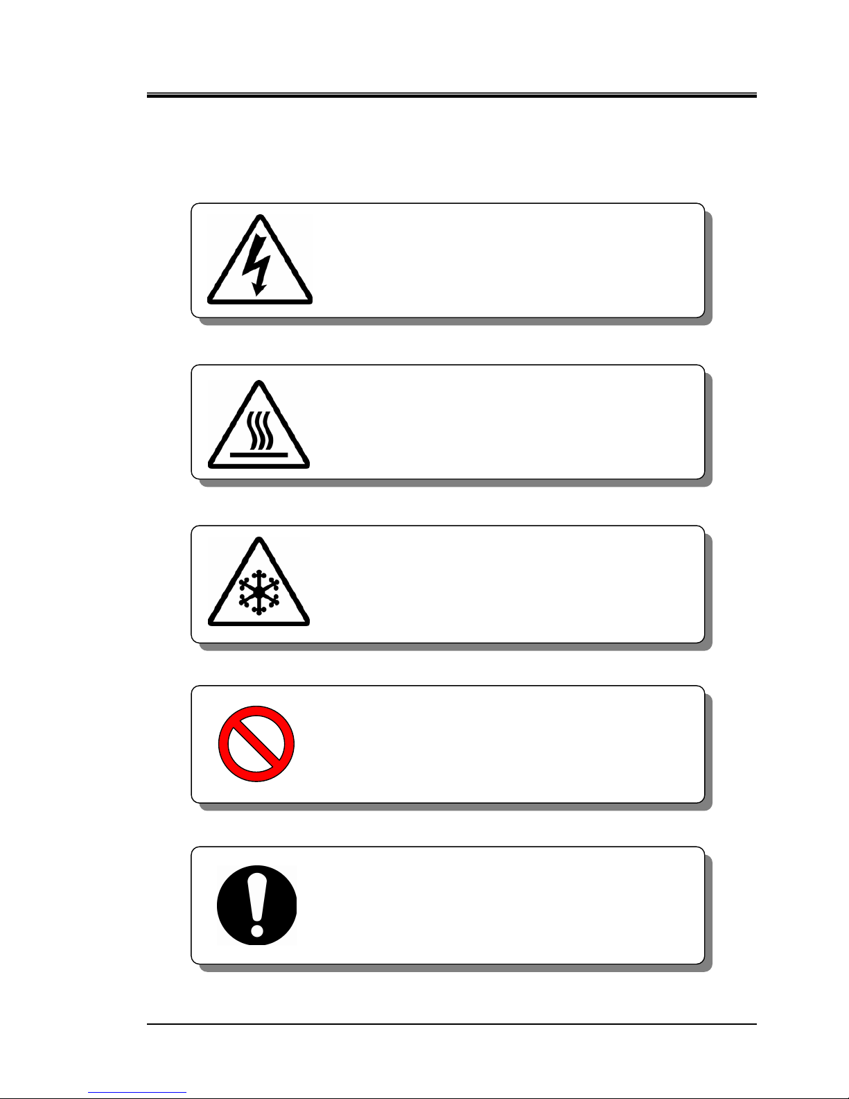
1.2.3 Symbols
This manual provides the following symbols in addition to “Danger”, “Warning”,
and “Caution” to highlight particular types of hazards.
Symbol of electrical hazard
Symbol of heat hazard
Symbol of low temperature hazard
Symbol of “Don’t”
Symbol of “Do”
This sign stands for prohibited actions.
This sign stands for actions that must be followed.
This symbol warns you of potential electrical shock.
This symbol warns you of a potential hot surface or
burn.
This symbol warns you of potential frostbite.
HRX-OM-M005
Chapter 1 Safety Instructions
1.3 Hazard Warning Label HRZD Series
1-4
1.3 Hazard Warning Label
The hazard warning labels are applied to the sections of the product where
potential hazards are present during product operation or maintenance.
The hazard warning labels are in appropriate sizes and colours to get attention of
the operator. They contain symbols in addition to the descriptions of the warnings.
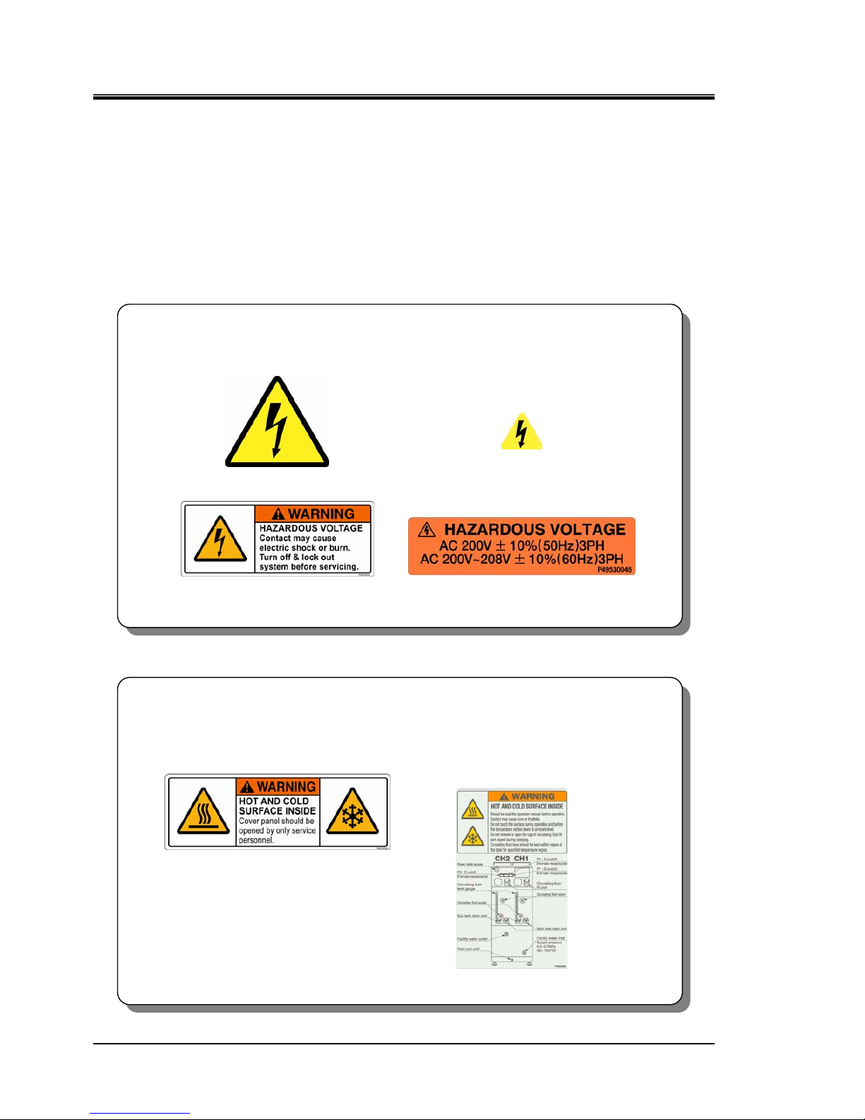
1.3.1 Type of hazard warning label
The hazard warning labels affixed on the product are listed below.
Labels of high voltage hazard
Labels of hot/cold surface hazard
[High voltage hazard]
This warning label is affixed on the cover panel which isolates the parts where high
voltage is used. Do not remove the cover panels that are not designated in this
manual.
Figure 1-2 Hazard warning label No.2
Figure 1-1 Hazard warning label No.1
Figure 1-4 Hazard warning label No.4 Figure 1-3 Hazard warning label No.3
[Hot/cold surface hazard]
This warning label is affixed on the surface that can be at high or low temperatures
and carry potential of burns or frostbite if touched. Residual heat may cause burns
despite the power being turned OFF. Be sure the surface has cooled before starting
work.
Figure 1-5 Hazard warning label No.5
Figure 1-6 Hazard warning label No.6
HRX-OM-M005
Chapter 1 Safety Instructions
HRZD Series 1.3 Hazard Warning Label
1-5
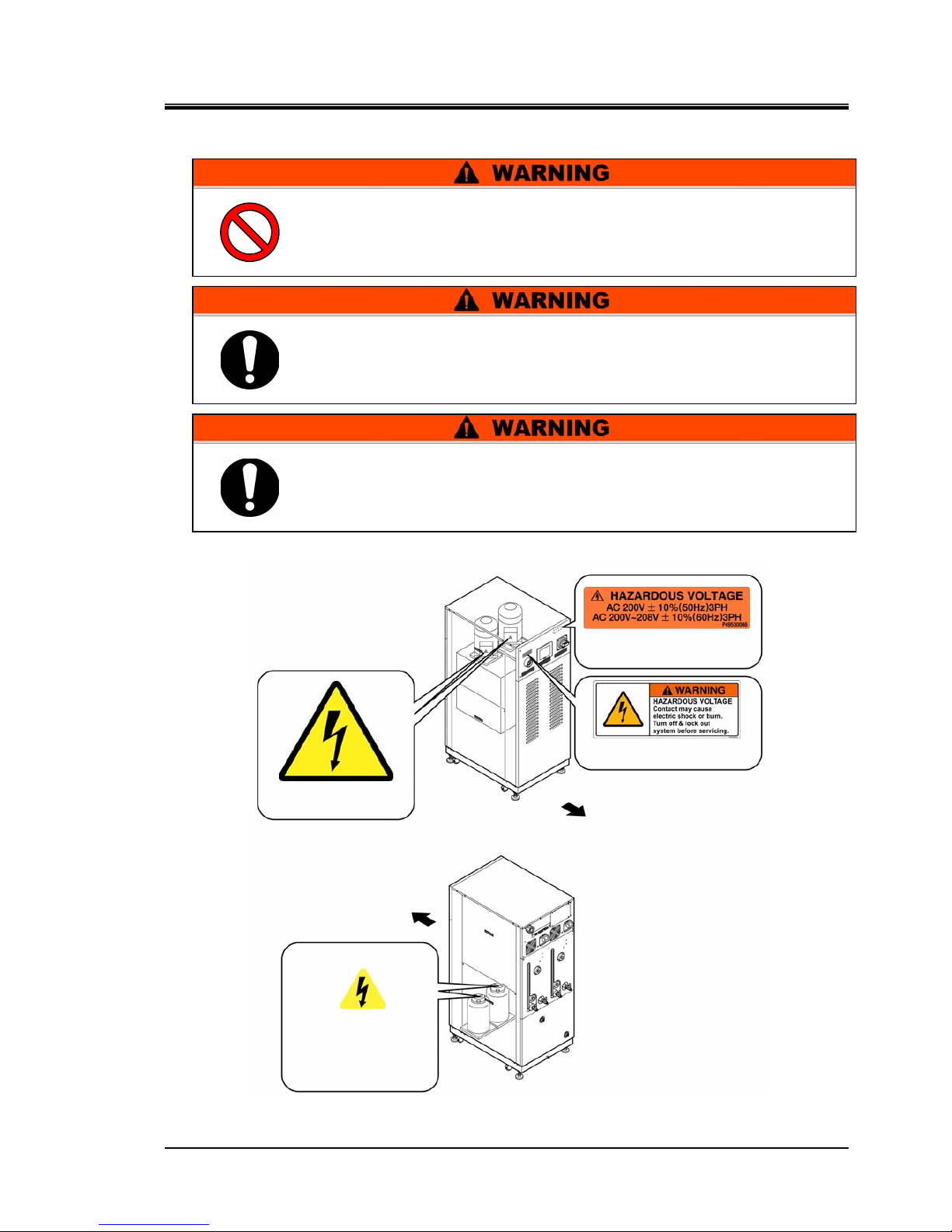
1.3.2 Location of hazard warning label
High voltage hazard
Figure 1-7 High Voltage Hazard
Do not peel off or deface the hazard warning labels.
Confirm the locations of all hazard warning labels.
Read the contents of the hazard warning labels carefully and keep
them in mind.
Users are NOT allowed to change the locations of the hazard warning
labels. If replacing a reeled off or worn out label, make sure to affix a
new label to exactly the same location of the old label.
Hazard warning label No.2
Front
Hazard warning label No.1
Front
Hazard warning label No.4
Hazard warning label No.3
HRX-OM-M005
Chapter 1 Safety Instructions
1.3 Hazard Warning Label HRZD Series
1-6
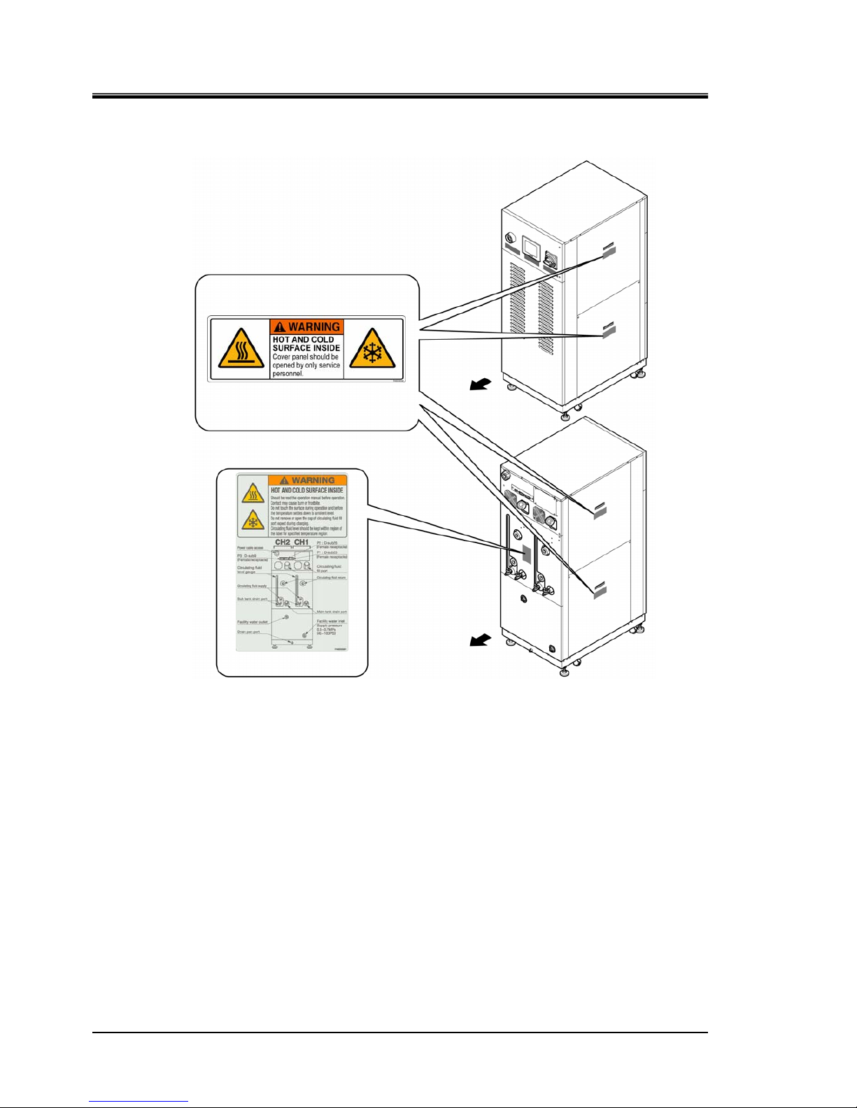
Hot/cold surface hazard
Figure 1-8 Hot/Cold Surface Hazard
Front
Rear
Hazard warning label No.5
Hazard warning label No.6
HRX-OM-M005
Chapter 1 Safety Instructions
HRZD Series 1.4 Location of Model Label
1-7
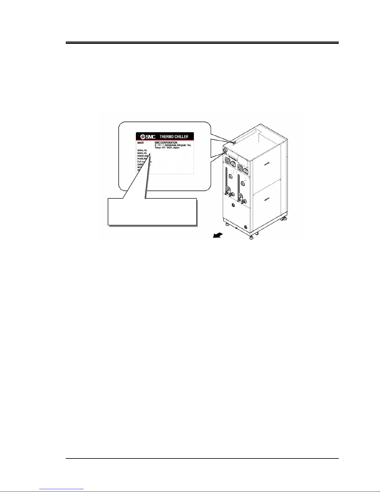
1.4 Location of Model Label
Information about the product, such as Serial No. and Model No. can be found on
the model label. This information is needed when contacting an SMC sales
distributor.
Figure 1-9 Location of Model Label
Model label
Rear
Serial No.
Model No.
HRX-OM-M005
Chapter 1 Safety Instructions
1.5 Safety Measures HRZD Series
1-8
1.5 Safety Measures
1.5.1 Safety Precautions
While the product is protected by various safety measures including the safety
interlocks, the following basic safety precautions should be observed to assure
further safe operations.
Read and undestand this manual carefully before using the product.
Before starting maintenance of the product, be sure to lock out and tag out the
breaker of user's power supply.
If operating the product during maintenance, be sure to inform all workers
nearby.
Use only the correct tools and procedures when installing or maintaning the
product.
Use personal protective equipment where specified (“1.5.4 Protective
equipment”).
Check all parts and screws are fitted correctly and securely after maintenance.
Avoid working in a drunken or sick condition, which might cause an accident.
Do not remove the panels except for the cases permitted in this manual.
Do not remove the panels during operation.
Use assistance to carry object over 20 kg.
Refer to your safety manual for emergency evacuation.
Follow the instructions below when using the product. Failure to
follow the instructions may cause an accident or injury.
HRX-OM-M005
Chapter 1 Safety Instructions
HRZD Series 1.5 Safety Measures
1-9
1.5.2 Safety Interlock system
Safety Interlock system
The function of the safety interlock system is not only to protect personnel by
restricting operation that may cause damage to the product or the facility around it
but also eliminate the danger relating to safety. The product is fitted with several
interlock functions that are activated when improper operation or hazardous
conditions occur. The product operation must be terminated when a safety
interlock is activated.
An alarm message is displayed on the operation touch panel when a safety
interlock is activated. See “Chapter 6 Error Message and Troubleshooting” for
details on the alarms and troubleshooting or see section “Troubleshooting” in a
separate volume of the “Service Manual”.
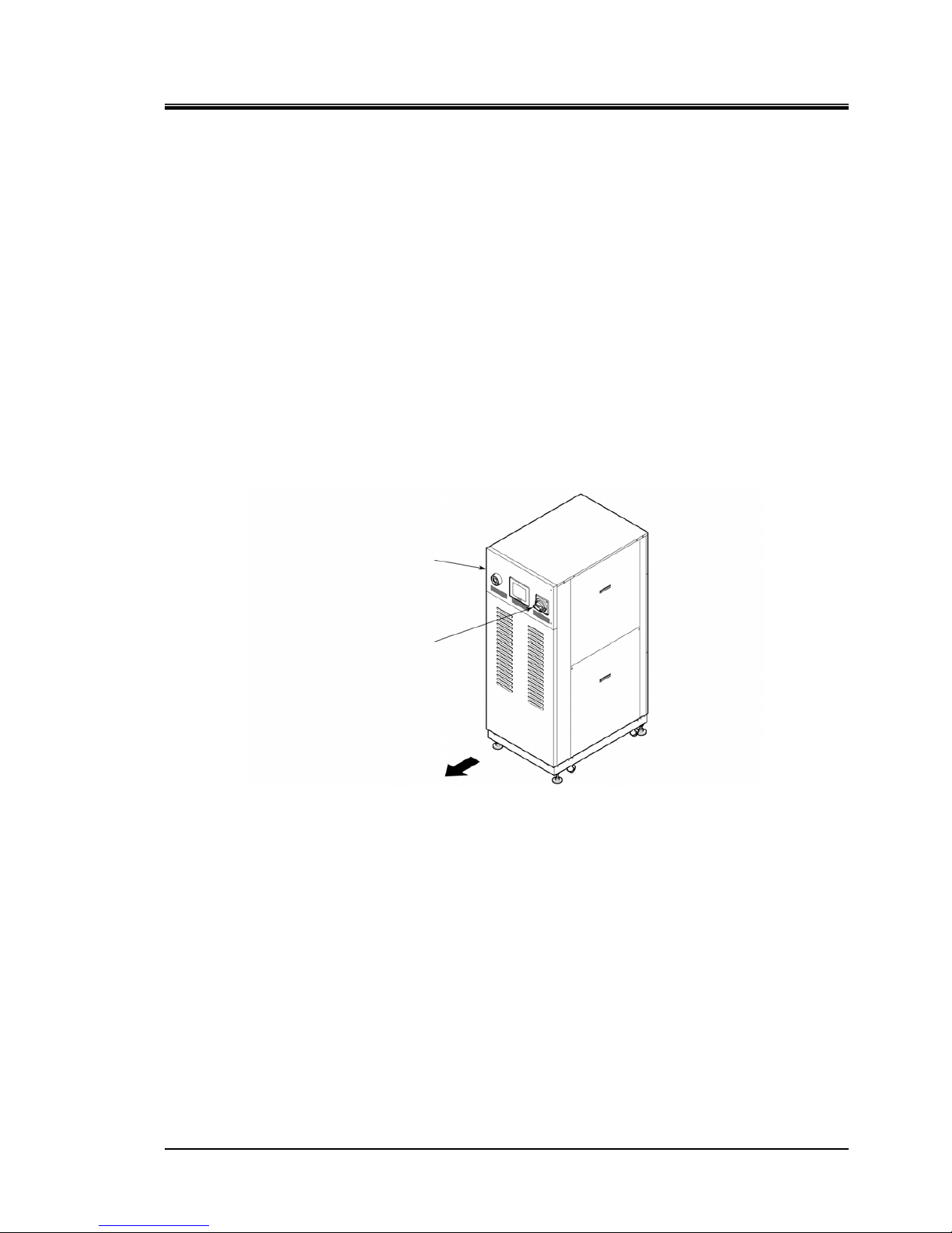
Front door
Product repair may require opening the front panel.
The breaker handle operation is available only with the front door closed.
Front
Front door
Breaker handle
Figure 1-10 Front Door
HRX-OM-M005
Chapter 1 Safety Instructions
1.5 Safety Measures HRZD Series
1-10
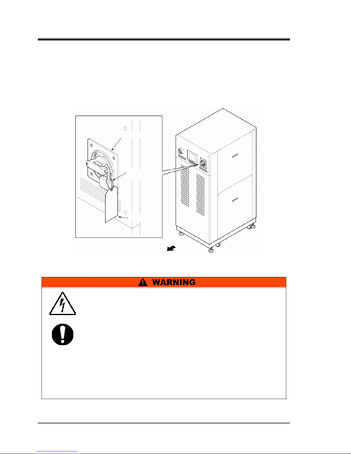
1.5.3 Lockout/Tagout
Summary
Lockout of the product disables the main breaker operation to prevent electric
shocks.
Tagout, to be placed on the locked out main breaker, prevents improper breaker
operation (ON) conducted by other personnel.
See “ Lockout procedure” in the following pages for a step-by-step guide to
lockout/tagout.
Main breaker
Padlock
Tag
Front
Figure 1-11 Lockout/Tagout
People performing service of the product should have an awareness of
the importance of lockout. Thorough understanding of the procedures
defined in this manual are required for product ser vice.
Lockout is allowed only when the product come to a full stop.
A supervisor should be appointed to direct all personnel if multiple
workers engage in system service.
The supervisor is to perform lockout based on a full understandin g of
overall process conditions.
Not only all personnel but new personnel that engage in service of t his
system should have an awareness of the importance of lockout and
obtain thorough understanding of the lockout procedure.
Any personnel working in an area with high voltage should be
assigned with padlocks and tags. The key for the padlock i s kept under
the responsibility of the supervisor , and l ockout rel ease is perfor med
upon completion of work.
HRX-OM-M005
Chapter 1 Safety Instructions
HRZD Series 1.5 Safety Measures
1-11
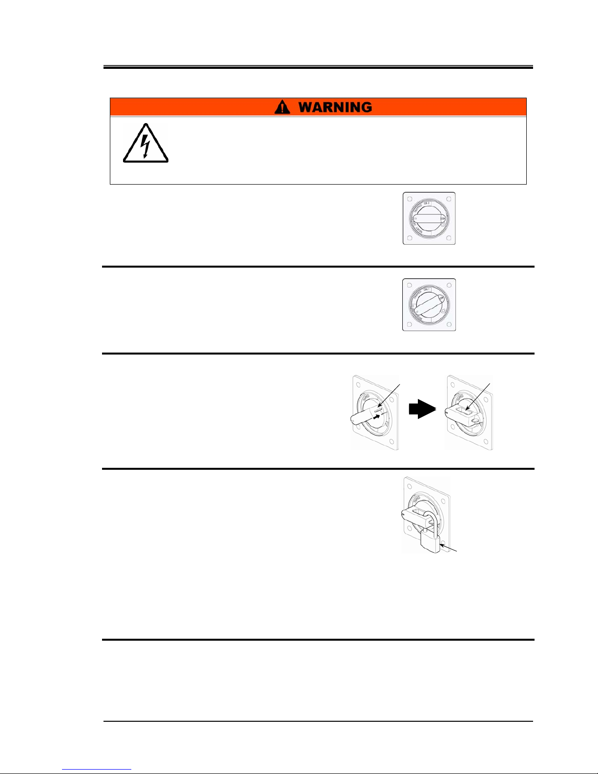
Lockout procedure
1. Turn the breaker handle to ‘OFF ’.
2. Turn the breaker handle to ‘RESET’.
Hold the breaker handle with hand.
The handle turns back to ‘OFF ’ if released.
3. Push the lock pushing part of the breaker
handle, and turn the breaker handle to
‘OFF ’.
The lock mechanism part is to remain opened.
4. Lock the lock mechanism part with the
padlock.
Releasing lockout
1. Remove the padlock from the lock mechanism part.
2. Turn the breaker handle to ‘RESET’.
The lock mechanism part is closed.
The handle turns back to ‘OFF ’ if released.
Figure 1-12 Breaker Handle at ‘OFF ’
Figure 1-13 Breaker Handle at ‘RESET’
Figure 1-14 Pushing of Lock Mechanism Part
Figure 1-15 Breaker Lock
All service personnel must observe the restrictions applied during
lockout and are required to perform lockout in accordance with this
procedure. No service personnel is allowed to start, energize, or use
the locked out product.
Padlock
Lock pushing part Lock mechanism part
HRX-OM-M005
Chapter 1 Safety Instructions
1.5 Safety Measures HRZD Series
1-12
1.5.4 Protective equipment
This manual specifies personal protective equipment for each work.
Transport, Installing and Uninstalling
Handling of circulating fluid
Operation
Always use safety shoes, gloves and head protection when
transporting, installing or uninstall the product.
Always use safety shoes, gloves, mask, apron and eye protection
when handling the circulating fluid.
Always use safety shoes and gloves when operating the product.
HRX-OM-M005
Chapter 1 Safety Instructions
HRZD Series 1.6 Emergency Measures
1-13
1.6 Emergency Measures
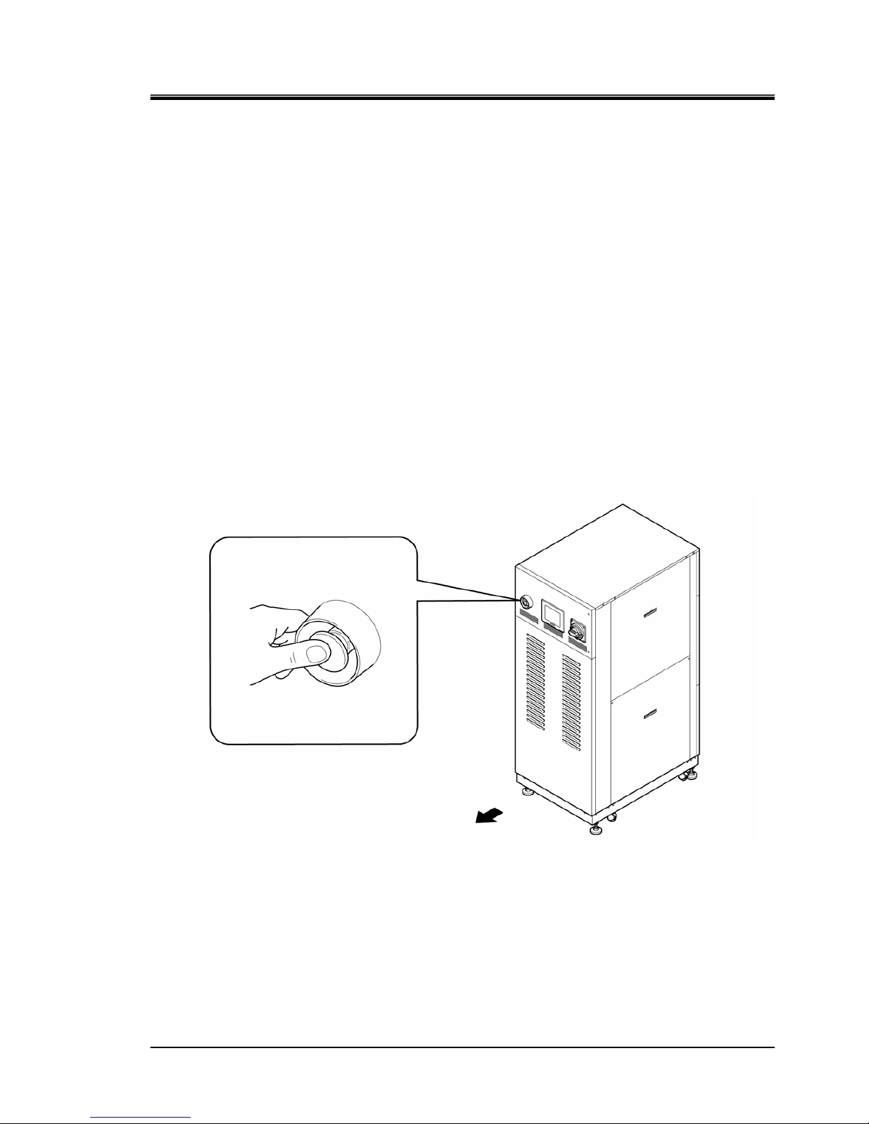
1.6.1 Emergency off [EMO] switch
Press the red emergency off [EMO] switch on the front of the product only if the
need to shut off the power arises due to emergency such as natural disaster, fire,
earthquake or personal injury.
The emergency off [EMO] switch is a large, red mushroom-shaped push button
labeled with ‘EMO’ on it. The product comes to a halt if this button is pressed.
When the emergency off [EMO] switch is pressed, the control power for the
product is shut off to bring the product to a stop. The main breaker of the product,
however, is designed not to trip, which enables the motor circuit to remain partially
energized. Please refer “8.1.2 Communication specification” in Chapter 8
Appendix on page 8-8 and construct a circuit which will cut off the power supply to
the customer device when the Em ergency C uto ff [EM O] swit ch is presse d using t he
EMO signal output from this device.
Restart of the product is enabled only when this button is reset manually.
Location of emergency off [EMO] switch
Figure 1-16 Location of Emergency Off [EMO] Switch
HRX-OM-M005
Chapter 1 Safety Instructions
1.6 Emergency Measures HRZD Series
1-14
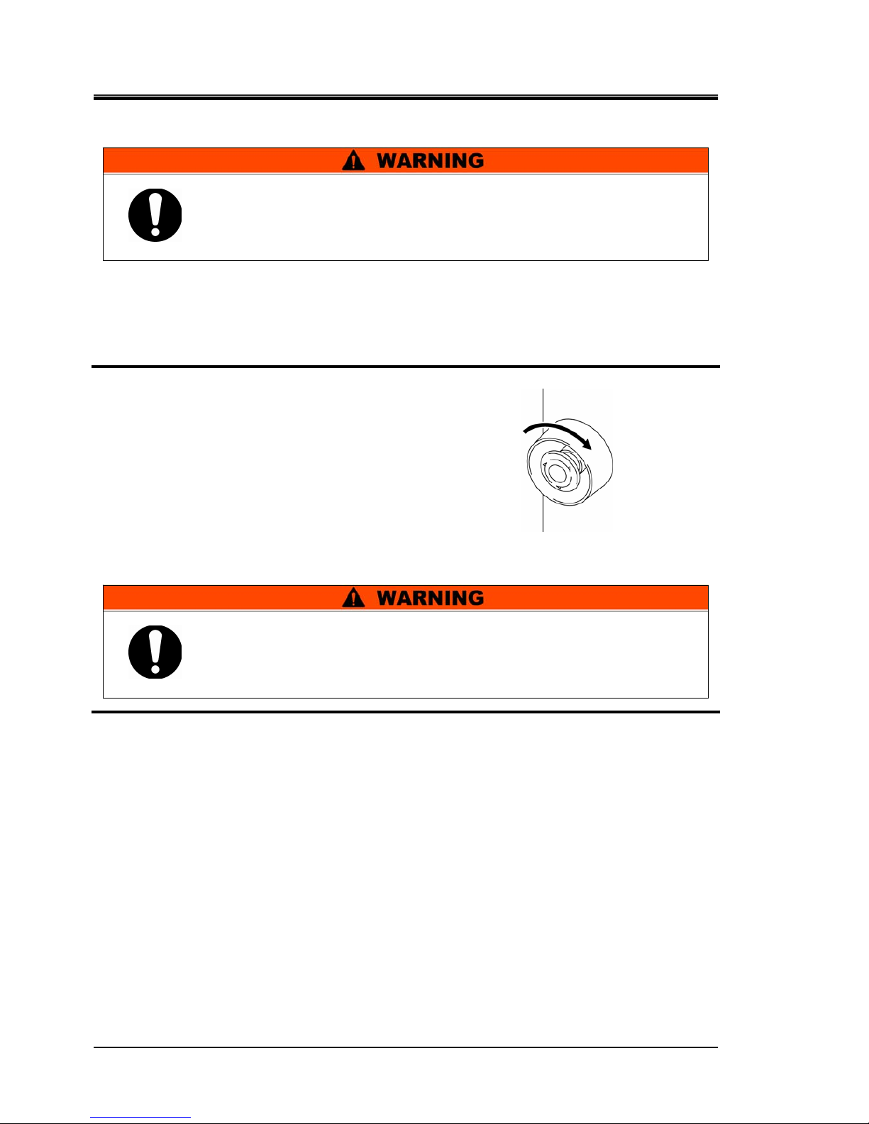
Reset of emergency off [EMO] switch
1. Before restarting, always make sure that the cause of the emergency off condition (The
reason why the EMO switch was activated) has been eliminated from the power supplies,
the prodcut or peripheral equipment.
2. With the cause completely eliminated,
turn the emergency off [EMO] switch
clockwise to reset.
The EMO button returns to its original position.
3. When the power is restored the product restarts as normal.
Figure 1-17 Emergency Off [EMO] Switch
No automatic recovery is applied to the emergency off [EMO] switch.
Always eliminate the cause of activating the EMO before resetting.
Potential serious accidents may occur if disregarded.
When the product is in remote mode, the remote mode is retained
despite the power outage. Thus the system operation is to resume as
the start signal is issued from your system.
HRX-OM-M005
Chapter 1 Safety Instructions
HRZD Series 1.7 Waste Disposal
1-15
1.7 Waste Disposal
1.7.1 Disposal of refrigerant and compressor oil
This product uses hydro-fluorocarbon type refrigerant (HFC) and compressor oil.
Comply with the law and regulation in each country for the disposal of refrigerant
and compressor oil. The type and quantity of refrigerant is described on the model
label. (“1.4 Model Label”)
If these fluids need to be recovered, read and understand the instructions below
carefully. If there is any unclear point, contact an SMC's sales distributor.
[Tips]
For the type and quantity of the refrigerant, see “Location of Model Label” on
page 1-7.
Always follow local regulations when disposing of this product or
related waste.
Only maintenance personnel or qualified people are allowed to
open the cover panels of the unit.
Do not mix the compressor oil with domestic waste for disposal.
Also, the disposal of the waste must only be conducted by specific
facilities that are permitted for that purpose.
•
Comply with the law and regulation in each country for the
disposal of refrigerant and compressor oil.
•
The release of refrigerant in to the atmosphere is banned by law.
Recover it with specific equipment and dispose of it correctly.
•
Only people who have sufficient knowledge and experience about
the unit and its accessories are allowed to recover the refrigerant
and compressor oil.

HRX-OM-M005
Chapter 1 Safety Instructions
1.8 Material Safety Data Sheet (MSDS) HRZD Series
1-16
1.7.2 Disposal of circulating fluid
The disposal of a circulating fluid must be handled by a specialized industrial
waste disposal agency. Ensure all circulating fluid is disposed of by such agency.
1.7.3 Disposal of product
The disposal of the product must be handled by a specialized industrial waste
disposal agency in accordance with local laws and regulations.
1.8 Material Safety Data Sheet (MSDS)
If the material safety data sheets of chemicals supplied in the product are needed,
contact an SMC's sales distributor.
Any chemicals used by the user must be accompanied by an MSDS.
HRX-OM-M005
Chapter 2 Name of Each Section
HRZD Series 2.1 Name of Each Section
2-1
Chapter 2 Name of Each Section
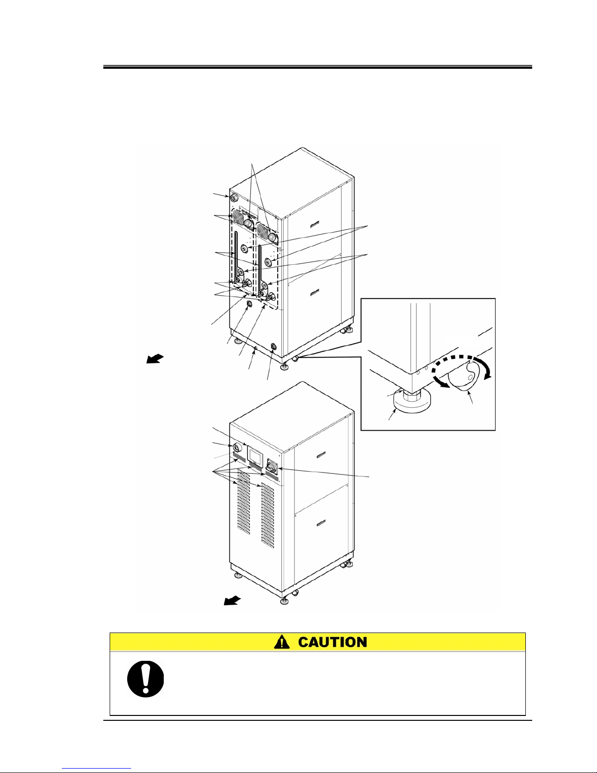
2.1 Name of Each Section
Figure 2-1 Name of Each Section
When transporting the product with the casters, raise the adjustable feet
(4 pcs.) to the highest position and lock them with the nuts.
The adjustable foot at the lower position may cause damage to this
system and personal injury through contact with the floor or steps
durin
g
product transport.
Operation touchpanel
Emer
g
ency off [EMO] switch
Main breaker
Ventilatin
g
hole (intake side)
Caster
Adjustable foot
Power cable access
Ventilating fan
(exhaust side)
Circulating fluid fill port
Facility water outlet
Circulating fluid return
Circulating fluid level
gauge
Drain pan port
Facility water inlet
Main tank drain
p
ort
Sub tank drain
p
ort
Circulating fluid supply
Nut
CH1 side
CH2 side
Rotates 360°
Rear
Front
Maintenance port

HRX-OM-M005
Chapter 2 Name of Each Section
2.1 Name of Each Section HRZD Series
2-2
HRX-OM-M005
Chapter 3 Transporting and Installation
HRZD Series 3.1 Transporting
3-1
Chapter 3 Transporting and Installation
3.1 Transporting
The product is heavy and has potential danger during transport. Also, to prevent
damage and failure of the product, be sure to follow these instructions for
transport.
If a fork lift is used for transport, check the forks are inserted in the
correct place, refer to section “3.1.1 Transporting with forklift” .
Proper procedure must be followed when using this product.
Exercise caution to assure personnel safety during the installation,
operation, maintenance and inspection of the product.
Only personnel, who have adequate knowledge and experiences with
not only the product but associated equipment are allowed to perform
transport, installation, and maintenance involving potential hazardous
task.
Never lay down the product. Oil in the compressor drains into the
refrigerant piping, which causes lubricant shortages leading to
damage to the compressor.
Drain the remaining fluid out of the piping as much as possible.
The remaining fluid may spill if disregarded.
Exercise caution not to damage the panel and piping with the forklift
when transporting the product.
HRX-OM-M005
Chapter 3 Transporting and Installation
3.1 Transporting HRZD Series
3-2
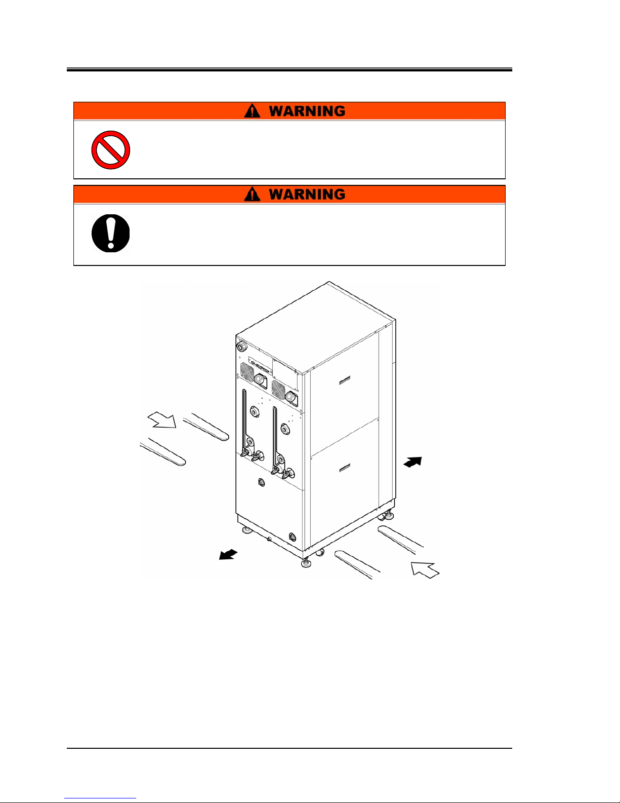
3.1.1 Transporting with forklift
Figure 3-1 Transport with Forklift
Rear
Front
Forklift insertion side
Forklift insertion side
Do not set the product on its side for transportation. Potential dama ge
to this system carrying danger of personne l injury if disr egarded.
Do not insert the fork from the back as well as front.
This product is heavy, and requires a forklift to safely move it.
Forklift insertion positions are on either left or right side of this
product. Always insert the forks all the way through. Be c areful no t to
hit the casters and adjustable feet .
HRX-OM-M005
Chapter 3 Transporting and Installation
HRZD Series 3.2 Installation
3-3
3.1.2 Transporting with caster
3.2 Installation
The product is heavy and requires assistance for this work. Exercise
caution and look out for sloped surfaces such as ramps, etc.
Product installation should be kept from areas with the potential of
flammable gas leak. Ignition may occur if leaked gas is collected
around the
p
roduct.
This product is NOT designed for outside use.
Potential electric shock, fire and damage may occur if exposed to rain,
w
ater and dust
.
Do not hold piping on the back of the product or panel handles when
transporting with the casters.
Potential damage to piping and panels may occur if disregarded.
The product is to be installed on a level floor that can withstand the
weight of the product. Potential water leak and personal injury due to
the product tipping over may occur if disregarded.

HRX-OM-M005
Chapter 3 Transporting and Installation
3.2 Installation HRZD Series
3-4
3.2.1 Installation conditions
The product must not be operated, installed, stored or trans port ed in the fo l lowi n g
conditions. Potential malfunction or damage to the product may occur if
disregarded.
The product does not conform to any Clean room specifications. The pump and
ventilating fan inside the product generate particles.
Location that is outside.
Location that is exposed to water, water vapour, steam, salt water or oil.
Location that is exposed to dust or powder material.
Location that is exposed to corrosive gas, organic solvent, chemical solution, or
flammable gas (the product is not flame-proo f)
Location where ambient temperature is out of the following range:
In transportation -40 to 70°C (with no water or circulating fluid in piping)
In storage 0 to 50°C (with no water or circulating fluid in piping)
In operation 10 to 35°C
Location where relative humidity is out of the following range:
In transportation and storage 15 to 85%
In operation 30 to 70%
Location that is subjected to abrupt changes in temperature
Location that is subjected to strong electromagnetic noise (intense electric field,
intense magnetic field, or surges)
Location that is subjected to static electricity, or conditions where static
electricity can discharge to the product
Location that is subjected to strong high frequencies raditation (microwaves)
Location that is subjected to potential lightning srtike
Location at altitudes of 1000m or higher (except for product storage and
transport)
Location where the product is affected by strong vibrations or impacts
Condition that applies external force or weight causing the product to be
damaged
Location without adequate space for maintenance as required
HRX-OM-M005
Chapter 3 Transporting and Installation
HRZD Series 3.2 Installation
3-5
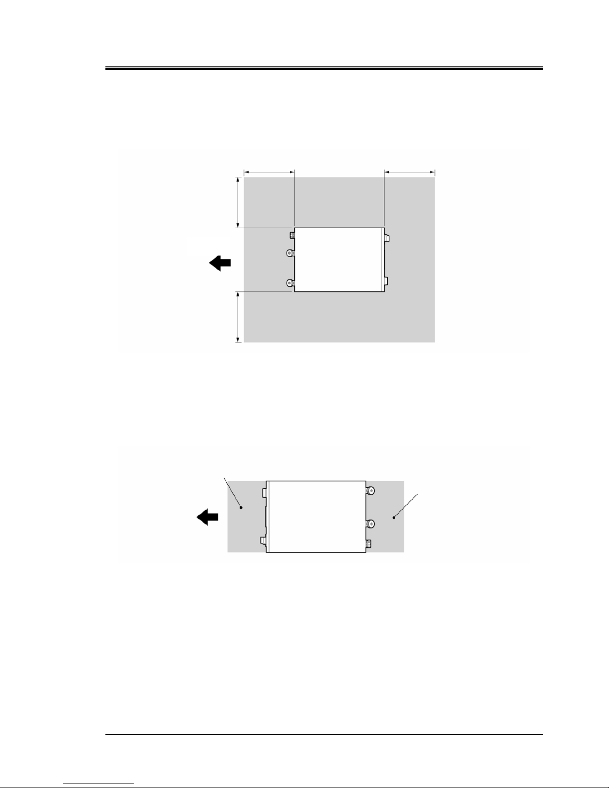
3.2.2 Installation location and maintenance work area
The product does not have any ventilating hole on the right and left sides. Although it can be
installed directly contacting walls or other devices, installation with maintenance space is
recommended. (See “Figure 3-2)
Figure 3-2 Recommended Installation Location
To save space, the product can be installed to allow access only in front and back for daily operation
and inspection. For maintenance and repair work, additional access space is required for the left and
right side of the product. We recommend a separate repair area, without taking space from
installation site, to accommodate the needed extra space.
Figure 3-3 Installation Location
Daily inspection area
Operation area
Front
Front
800mm 800mm
800mm
800mm
HRX-OM-M005
Chapter 3 Transporting and Installation
3.3 Procedure for Installation HRZD Series
3-6
3.3 Procedure for Installation
3.3.1 Installation
Product installation should be on a vibration-free, stable and level surface.
See “Appendix 8.2 Outer Dimensions” in Chapter 8 on page 8-11 fo r t he
dimensions of this product.
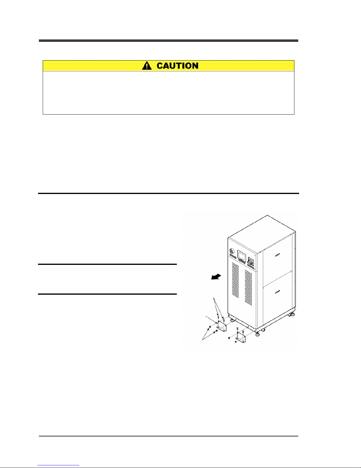
3.3.2 Procedure for product securing
Adjust and secure the adjustable feet of the product to secure the anti-seismic
bracket.
1. Transfer the product to the installation site.
2. Adjust the adjustable foot with a 24-mm
open end wrench.
Level the product (using a leveler) by
adjusting the adjustable feet.
All adjustable feet (4 pcs.) must touch the
floor completely.
Casters need not be touching the floor.
3. Attach the anti-seismic bracket (4pcs.) to
the front side and the rear side.
4. Secure the anti-seismic bracket with the
anchor bolts. Repeat precedures for
additional brackets.
Figure 3-4 Anti-seismic Bracket Attachment
Anti-seismic bracket is recommended for the installation of the product.
Preparation of anchor bolts suitable for floor material is your respons ibility .
M12-anchor bolts (8 pcs.) are required. See “Appendi x 8.6 Anchor Bolt Mounting
Position” in Chapter 8 on page 8-12”.
M8 nut (8 pcs.)
(accessory)
Anti-seismic
bracket
(accessory)
M12 anchor bolt
Front
 Loading...