

HRX-OM-I051-P
HRZ001-L
HRZ002-L
HRZ004-L
HRZ008-L
HRZ001-L1
HRZ002-L1
HRZ004-L1
HRZ008-L1
HRZ001-L2
HRZ002-L2
HRZ004-L2
HRZ008-L2
HRZ001-H
HRZ002-H
HRZ004-H
HRZ008-H
HRZ001-H1
HRZ002-H1
HRZ004-H1
HRZ008-H1
HRZ002-W
HRZ008-W
HRZ002-W1
HRZ008-W1
HRZ010-WS
HRZ010-W1S
HRZ010-W2S
1stEdition:January.2005
17thEdition:Sep.2016
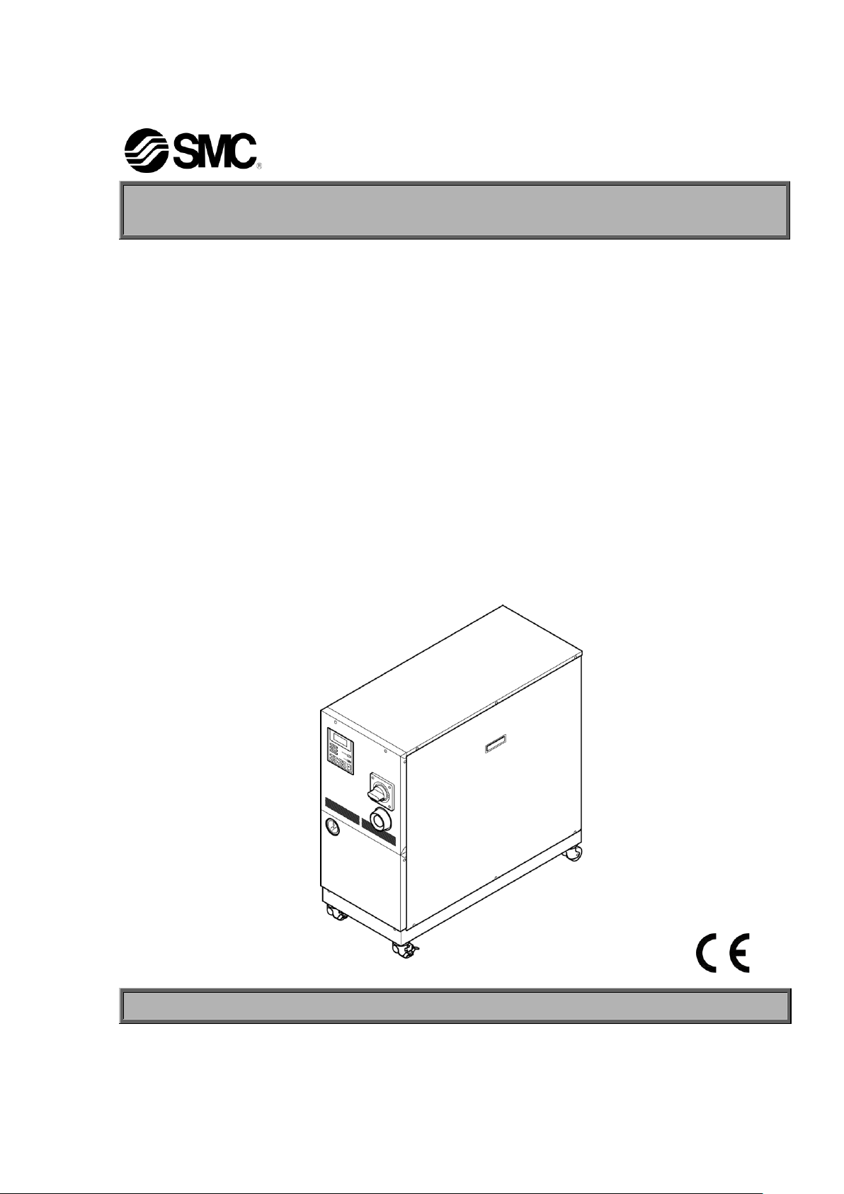
Operation Manual
Original Instructions
Thermo-Chiller
Save This Manual Carefully for Use at Any Time
© 2016 SMC CORPORATION All Rights Reserved
To the Customers
Note: The contents of this manual are subject to change without notice.
Akihabara UDX 15F,
4-14-1, Sotokanda, Chiyoda-ku, Tokyo 101-0021,JAPAN
Phone: +81 3 5207 8249 Fax: +81 3 5298 5362
URL http://www.smcworld.com
Thank you for purchasing our THERMO CHILLER HRZ Series (hereinafter called “This system”).
For the long-term, safe use of this system, be sure to read and understand this manual thoroughly before performing
operation of this system.
Warnings and precautions defined in this manual shall be observed.
This manual provides the explanations of the installation and operation of this system. Only those who have
thorough understanding of the fundamental operating procedure or have basic knowledge and skills of handling
industrial equipment for the installation and operation of this system are qualified to perform installation and
operation.
The contents of this manual and related documents supplied with this system shall be neither regarded as a
provision of the contract nor utilized to correct or modify the existing agreements, commitments and relations.
Copying, duplicating or transferring any part of or whole contents of this manual without the prior written consent
of SMC Corporation is strictly prohibited.
The Service Manual is supplied in addition to this manual and provides the explanations of the inspection,
troubleshooting, and in-depth remedies of this system. The Service Manual is intended for service personnel that
completed service training SMC provides. Only those who fall under the above condition are allowed to perform
maintenance and repair of this system with the use of the Service Manual.

HRX-OM-I051
TOC-1
Table of Contents
Table of Contents
Chapter 1 Safety.................................................................................... 1-1
1.1 Before Using this System ....................................................................................... 1-1
1.2 Danger, Warning, and Caution Used in This Manual............................................. 1-2
1.2.1 Hazard Levels ..................................................................................................................... 1-2
1.2.2 Definitions of “Serious injury” and “Minor injury” ................................................................. 1-2
1.2.3 Symbols ............................................................................................................................... 1-3
1.3 Hazard Warning Label ............................................................................................. 1-4
1.3.1 Type of hazard warning label .............................................................................................. 1-4
1.3.2 Location of hazard warning label ........................................................................................ 1-5
1.4 Location of Model Label ......................................................................................... 1-7
1.5 Safety Measures ...................................................................................................... 1-8
1.5.1 Safety Precautions .............................................................................................................. 1-8
1.5.2 Safety Interlock system ....................................................................................................... 1-9
1.5.3 Lockout/Tagout .................................................................................................................. 1-10
1.5.4 Protective equipment ......................................................................................................... 1-12
1.6 Emergency Measures............................................................................................ 1-13
1.6.1 Emergency off [EMO] switch ............................................................................................. 1-13
1.7 Waste Disposal ...................................................................................................... 1-15
1.7.1 Disposal of refrigerant and compressor oil........................................................................ 1-15
1.7.2 Circulating fluid disposal.................................................................................................... 1-16
1.7.3 System disposal ................................................................................................................ 1-16
1.7.4 Lavel .................................................................................................................................. 1-16
1.8 Material Safety Data Sheet (MSDS) ...................................................................... 1-16
Chapter 2 Name of Each Section ......................................................... 2-1
2.1 Name of Each Section (1) ....................................................................................... 2-1
2.2 Name of Each Section (2) ....................................................................................... 2-2
Chapter 3 Transporting and Installation .............................................. 3-1
3.1 Transporting ................................................................ ............................................ 3-1
3.1.1 Transporting with forklift ...................................................................................................... 3-2
3.1.2 Transporting with caster ...................................................................................................... 3-3
3.2 Installation ............................................................................................................... 3-3
3.2.1 Installation conditions .......................................................................................................... 3-4
3.2.2 Installation location and maintenance work area ................................................................ 3-5
3.3 Procedure for Installation ....................................................................................... 3-6
3.3.1 Installation ........................................................................................................................... 3-6
3.3.2 Procedure for system securing (1) ...................................................................................... 3-6
3.3.3 Procedure for system securing (2) ...................................................................................... 3-7
HRZ Series

HRX-OM-I051
TOC-2
Table of Contents
3.3.4 Wiring installation ................................................................................................................. 3-8
3.3.5 Procedures for wiring installation ....................................................................................... 3-11
3.3.6 Installation of circulating fluid and facility water piping ...................................................... 3-14
Chapter 4 System Startup and Shutdown .............................................. 4-1
4.1 Pre-check .................................................................................................................. 4-1
4.1.1 Installation condition ............................................................................................................ 4-1
4.1.2 Cable connection ................................................................................................................. 4-1
4.1.3 Installation of circulating fluid and facility water piping ........................................................ 4-1
4.1.4 Operating signal from your system ...................................................................................... 4-1
4.1.5 Check emergency off [EMO] switch .................................................................................... 4-1
4.2 Opening of Facility water Valve .............................................................................. 4-1
4.3 Supply of Circulating Fluid ...................................................................................... 4-2
4.3.1 Preparation of circulating fluid ............................................................................................. 4-2
4.3.2 Supply of circulating fluid ..................................................................................................... 4-3
4.4 Requirement for System Startup ............................................................................ 4-4
4.4.1 Turning ON power................................................................................................................ 4-4
4.4.2 Circulating fluid temperature setting .................................................................................... 4-5
4.5 System Startup and Shutdown ................................................................................ 4-5
4.5.1 System startup ..................................................................................................................... 4-5
4.5.2 System shutdown ................................................................................................................ 4-5
Chapter 5 System Operation ................................................................ 5-1
5.1 Operation Display Panel .......................................................................................... 5-1
5.2 Flow Chart of Operation Screen.............................................................................. 5-2
5.3 Operation Screen ..................................................................................................... 5-3
5.3.1 Model Indication screen ....................................................................................................... 5-3
5.3.2 Status screen 1 .................................................................................................................... 5-3
5.3.3 Status screen 2 .................................................................................................................... 5-4
5.3.4 Status screen 3 .................................................................................................................... 5-4
5.3.5 Status screen 4 .................................................................................................................... 5-5
5.3.6 Menu screen ........................................................................................................................ 5-5
5.3.7 Setting screen ...................................................................................................................... 5-6
5.3.8 Mode Selection screen ........................................................................................................ 5-7
5.3.9 Initial Setting screen ............................................................................................................ 5-7
5.3.10 Maintenance screen ............................................................................................................ 5-9
5.3.11 Option screen ...................................................................................................................... 5-9
5.3.12 Alarm Display screen ......................................................................................................... 5-10
5.3.13 System Information screen ................................................................................................ 5-10
5.4 Examples of System Operation ............................................................................ 5-11
5.4.1 Example 1: Circulating fluid set temperature is changed from 23.0°C to 34.1°C. ............. 5-11
HRZ Series

HRX-OM-I051
TOC-3
Table of Contents
5.4.2 Example 2: Communication mode is switched from “DIO REMOTE” to “LOCAL”. ........... 5-13
5.4.3 Example 3: Alarm signal of contact signal is changed from “N/A” to “ALARM1”. ............. 5-14
Chapter 6 Error Message and Troubleshooting .................................. 6-1
6.1 Error Message ................................................................................................ ......... 6-1
6.2 Troubleshooting ...................................................................................................... 6-2
Chapter 7 System Maintenance ........................................................... 7-1
7.1 Water Quality Management ..................................................................................... 7-1
7.2 Inspection and Cleaning ......................................................................................... 7-2
7.2.1 Daily inspection ................................................................................................................... 7-2
7.2.2 Quarterly inspection ............................................................................................................ 7-3
7.3 Storage ..................................................................................................................... 7-3
7.3.1 Draining of circulating fluid out of tank ................................................................................ 7-4
7.3.2 Draining of facility water ...................................................................................................... 7-5
7.4 Periodic Replacement Parts ................................................................................... 7-6
Chapter 8 Appendix .............................................................................. 8-1
8.1 Specification ............................................................................................................ 8-1
8.1.1 System specification ............................................................................................................ 8-1
8.1.2 Communication specification.............................................................................................. 8-11
8.1.3 Alarm signal selection ....................................................................................................... 8-13
8.2 Outer Dimensions ................................................................................................. 8-14
8.2.1 Part 1 ................................................................................................................................. 8-14
8.2.2 Part 2 ................................................................................................................................. 8-14
8.2.3 Part 3 ................................................................................................................................. 8-15
8.3 Flow Chart .............................................................................................................. 8-16
8.3.1 Part 1 ................................................................................................................................. 8-16
8.3.2 Part 2 ................................................................................................................................. 8-17
8.4 Offset Function ...................................................................................................... 8-18
8.4.1 Example of offset function ................................................................................................. 8-19
8.5 BAND/READY function ......................................................................................... 8-21
8.6 Anchor Bolt Mounting Position ............................................................................ 8-22
8.6.1 Part 1 ................................................................................................................................. 8-22
8.6.2 Part 2 ................................................................................................................................. 8-23
8.7 Compliance ............................................................................................................ 8-24
8.8 Thermo Chiller Daily Inspection Sheet ................................................................ 8-25
HRZ Series

HRX-OM-I051
TOC-4
Table of Contents
HRZ Series

1-1
Chapter 1 Safety
Be sure to read and understand the important precautions defined in
this manual thoroughly prior to system use.
1.1 Before Using this System
This "Safety" chapter describes the safety-related items that users should be
aware of upon handling this system.
This system, which is operated under high voltage, is outfitted with the parts
that cause a rise or drop in temperature and rotating parts when it is in action,
All personnel who work with or around this system are required to thoroughly
read and understand the safety-related items in this manual prior to working
with or around this system.
This manual is not intended to be used as a manual for comprehensive safety
and hygiene education. Such a manual should be provided by a safety training
manager.
HRX-OM-I051
Chapter 1 Safety
All personnel who work on or around this system are to have proper training
and education on dangers specific to this system and safety measures against
potential hazards.
A safety manager is responsible for observing safety standards. Operators and
maintainers, however, are to have individual responsibilies for complying with
the safety standard in his/her daily work.
Operators and maintainers must individually take account of safety and assure a
proper working area and working environment.
The relevant personnel must receive proper safety education prior to work
training on this system. Otherwise, personnel may be exposed to hazards. Never
conduct work training without giving proper consideration to safety.
Save this manual at a designated place for reference when necessary.
HRZ Series 1.1 Before Using this System
HRX-OM-I051
1-2
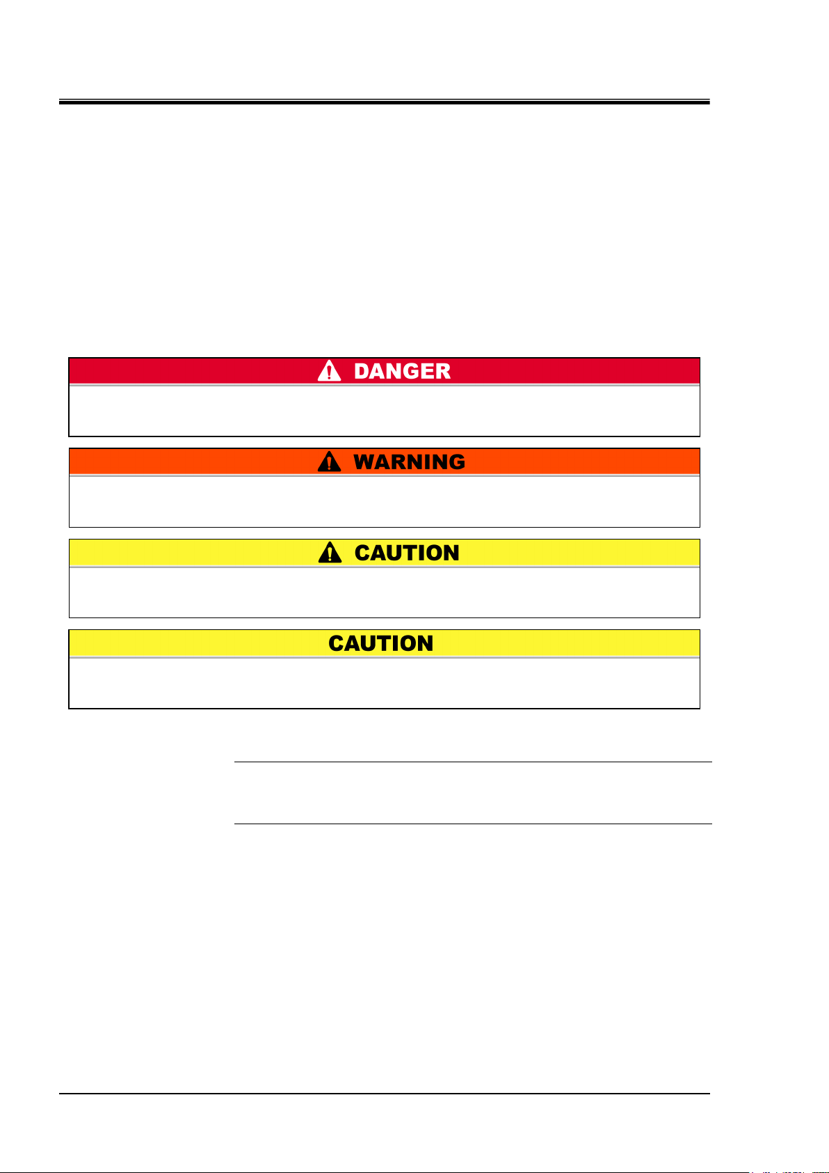
"DANGER" denotes that there is an imminent hazard which will cause serious
personal injury or death during operation.
"WARNING" denotes that there is a hazard which may cause serious personal injury
or death during operation.
"CAUTION" denotes that there is a hazard which may cause minor personal injury
during operation.
"CAUTION" without an exclamation symbol denotes that there is a hazard which
may cause damage or failure of this system, facility, or devices.
Chapter 1 Safety
1.2 Danger, Warning, and Caution Used in This
Manual
1.2.1 Hazard Levels
This system is designed with its first priority being the safety of workers and the
prevention of system damage. This manual classifies the risks into the following
three categories according to the severity and level of the hazard; Danger, Warning,
and Caution. Read the statements carefully, thoroughly understand them before
operating this system.
DANGER, WARNING and CAUTION signs are in order according to hazard
severity (DANGER > WARNING > CAUTION). See below for the details.
[Tips]
Tips are provided when there is information personnel are required to be
aware of for system operation and maintenance. If the task carries useful
information, the relevant tips are given as well.
1.2.2 Definitions of “Serious injury” and “Minor injury”
“Serious injury”
This term describes injuries such as loss of eyesight, wound, burns, frostbite,
electric shock, fracture, and toxication that leave aftereffects, and/or injury
requiring hospitalization and/or prolonged staying in a hospital.
“Minor injury”
This term describes injuries that do not require hospitalization or prolonged staying
in a hospital (injuries other than “serious injuries” described above).
1.2 Danger, Warning, and Caution Used in This Manual HRZ Series
1-3
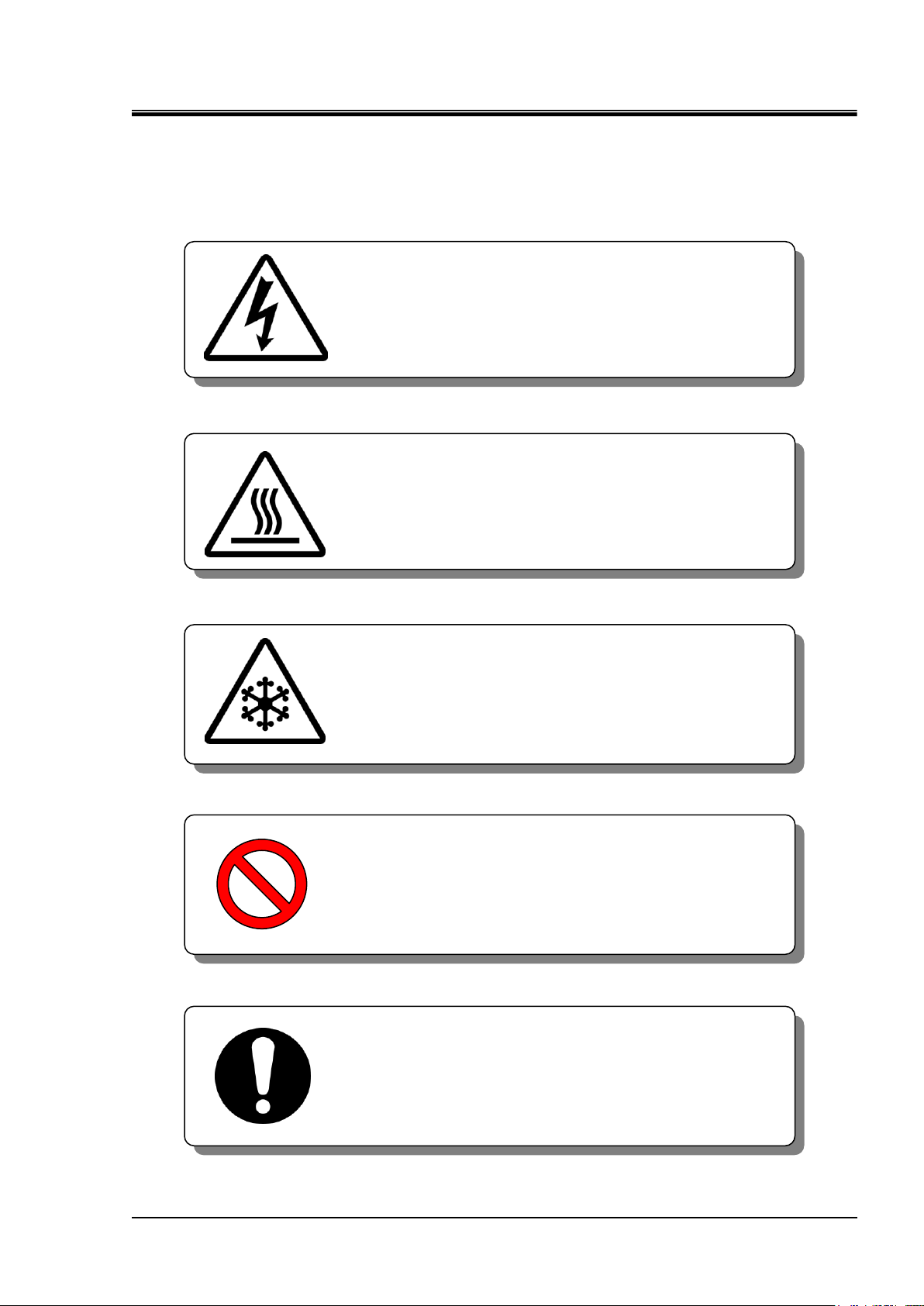
1.2.3 Symbols
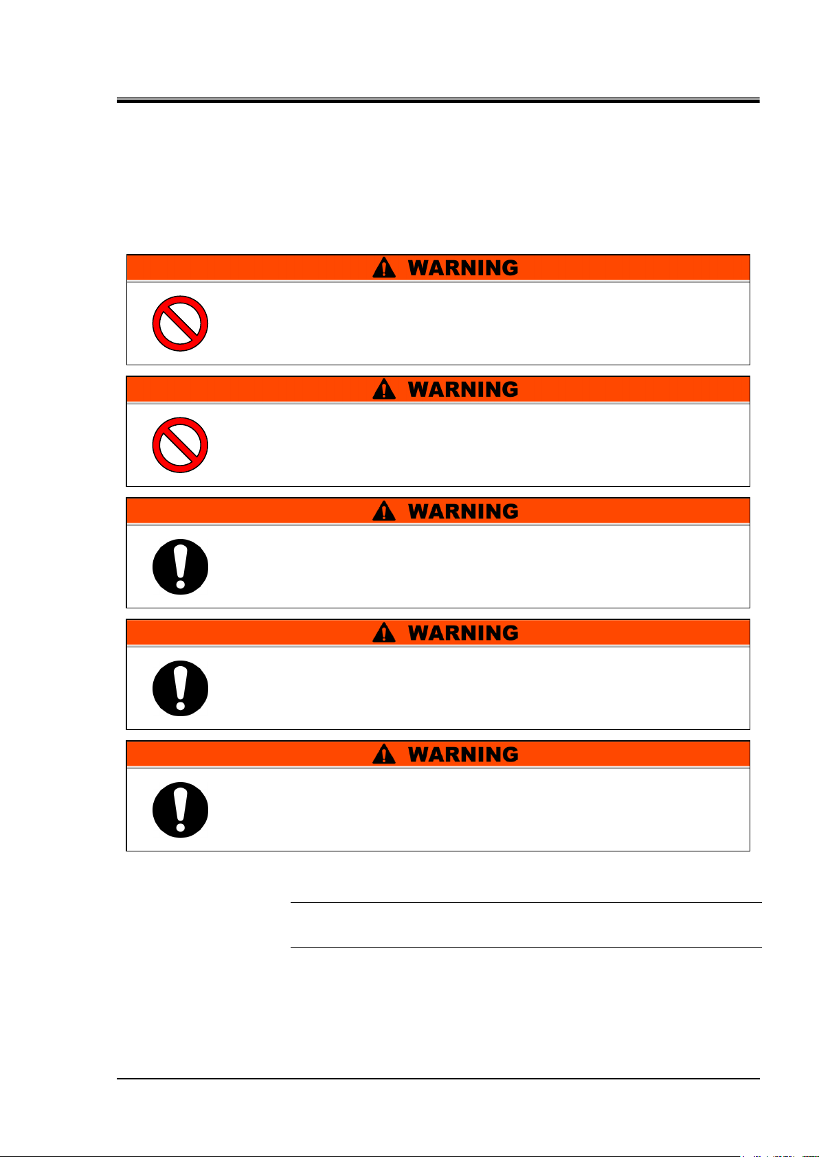
This symbol denotes “Don’t” item which you must
not do in operation of this system.
This symbol denotes the “obligation” items which
you must follow in operation of this system.
This symbol warns you of potential electrical shock.
This symbol warns you of potential burns.
This symbol warns you of potential frostbite.
This manual provides the following symbols in addition to “Danger”, “Warning”,
and “Caution” to present the warning details in easy-to-understand manner.
Symbol of electrical hazard
Symbol of heat hazard
HRX-OM-I051
Chapter 1 Safety
Symbol of low temperature hazard
Symbol of “Don’ts”
Symbol of “Required Action”
HRZ Series 1.2 Danger, Warning, and Caution Used in This Manual
HRX-OM-I051
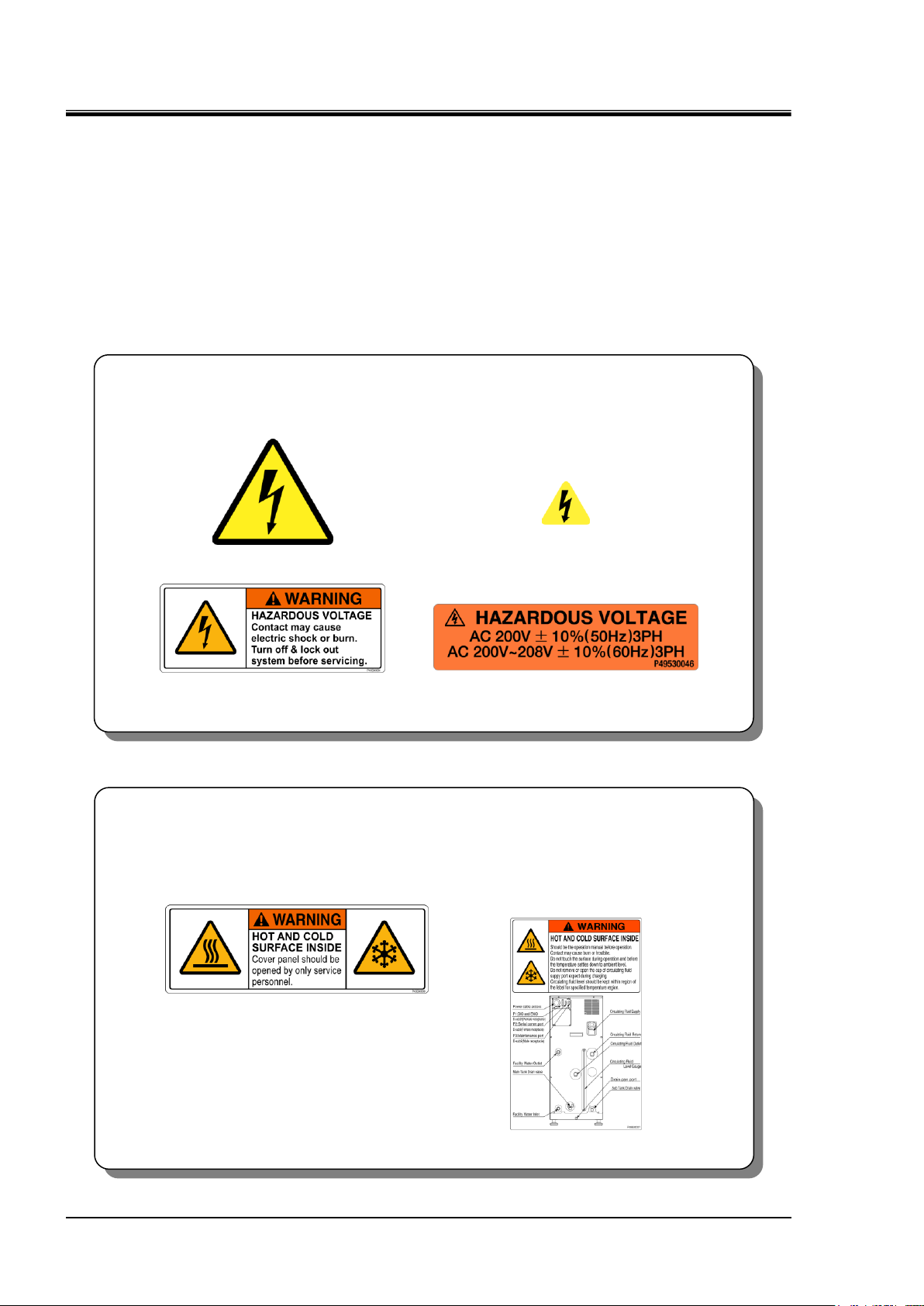
1-4
[High voltage hazard]
This warning label is affixed on the part isolated with the cover panel of the system
panel in which high voltage is applied.
Do not remove cover panels that are not designated in this manual.
Figure 1-1 Hazard warning label No.1
Figure 1-2 Hazard warning label No.2
Figure 1-3 Hazard warning label No.3
Figure 1-4 Hazard warning label No.4
[Hot/cold surface hazard]
This warning label is affixed on the surface that is at high or low temperatures
carrying potential burns (or frostbite) if touched. Residual heat may cause burns
despite the power being turned OFF. Be sure of the surface reaching room
temperature before work.
Figure 1-5 Hazard warning label No.5
Figure 1-6 Hazard warning label No.6
Chapter 1 Safety
1.3 Hazard Warning Label
The hazard warning labels are applied to the sections of this system where
potential hazards are present during system operation and maintenance.
The hazard warning labels are in appropriate sizes and colors to get attention of the
operator. They contain symbols in addition to the descriptions of warnings.
1.3.1 Type of hazard warning label
The hazard warning labels affixed on this system are listed below.
Labels of high voltage hazard
Labels of hot/cold surface hazard
1.3 Hazard Warning Label HRZ Series
1-5
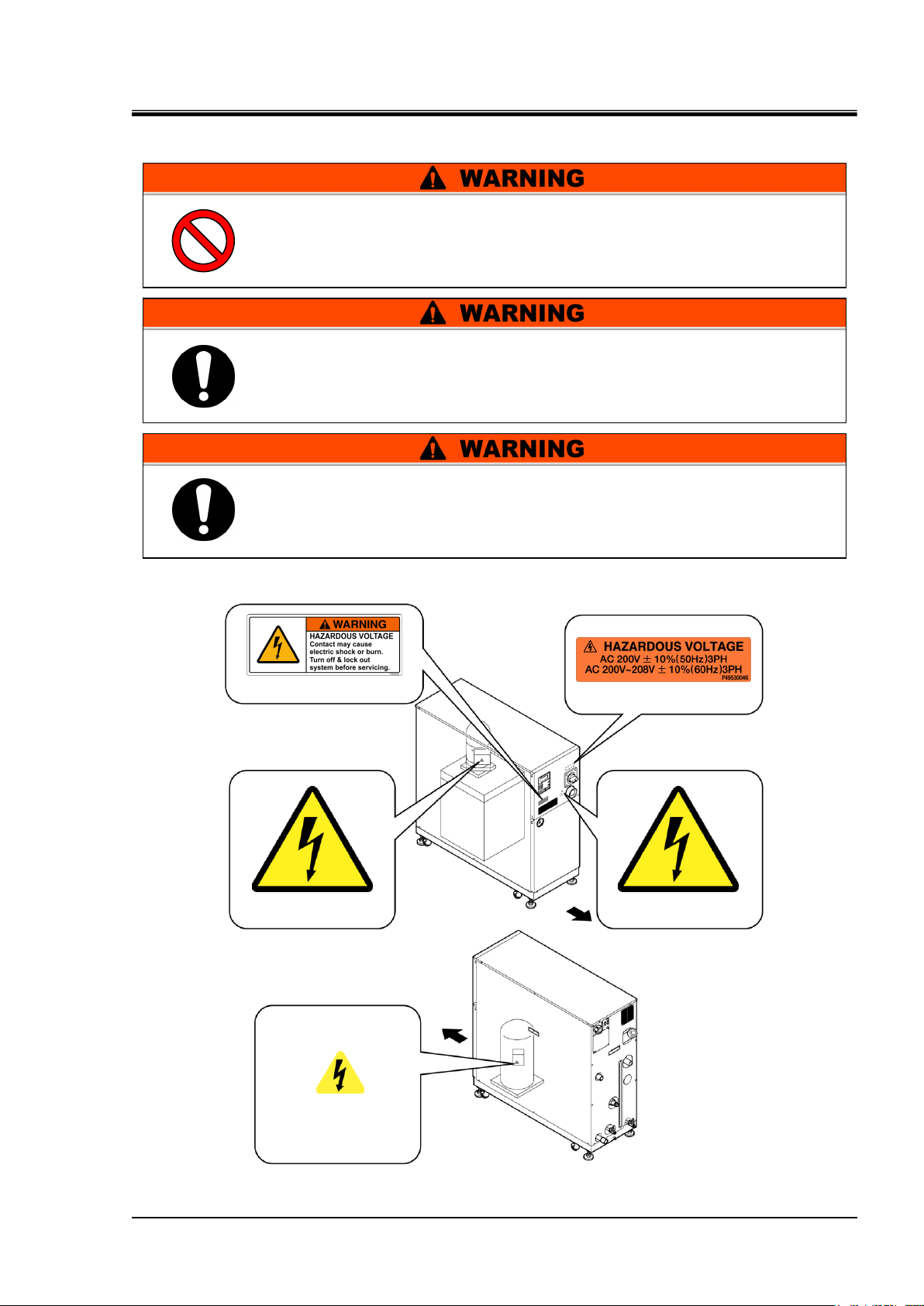
1.3.2 Location of hazard warning label
Figure 1-7 High Voltage Hazard
Confirm the locations of the hazard warning labels.
Read the contents of the hazard warning labels carefully and keep them in
mind.
Do not peel off or deface the hazard warning labels.
Users are NOT allowed to change the locations of the hazard warning
labels. Make sure to affix a new label to exactly the same location of
the replaced label upon replacement of the peeled off or worn out
label.
Hazard warning label No.2
Front
Hazard warning label No.3
Hazard warning label No.1
Front
Hazard warning label No.4
Hazard warning label No.1
HRX-OM-I051
Chapter 1 Safety
High voltage hazard
HRZ Series 1.3 Hazard Warning Label
HRX-OM-I051
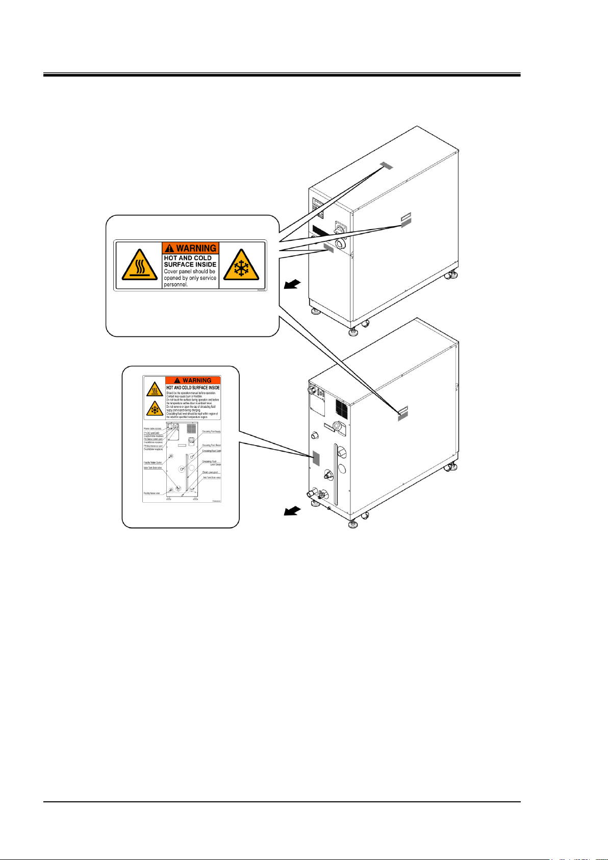
1-6
Figure 1-8 Hot/Cold Surface Hazard
Front
Rear
Hazard warning label No.5
Hazard warning label No.6
Chapter 1 Safety
Hot/cold surface hazard
1.3 Hazard Warning Label HRZ Series

1-7
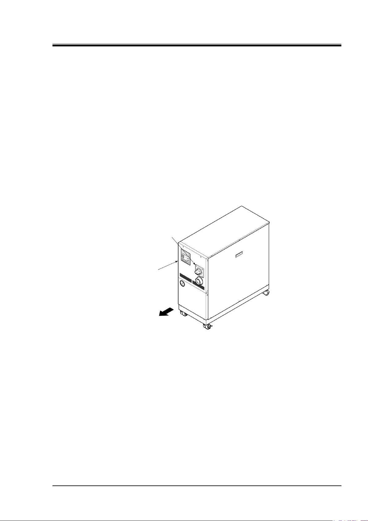
1.4 Location of Model Label
Figure 1-9 Location of Model Label
Label
Rear
Serial No.
Model No.
Front
Information on your system such as Serial No. and Model No. need to be furnished
when you contact the store you purchased from. Serial No. and model No. are
listed on the label as shown below.
HRX-OM-I051
Chapter 1 Safety
HRZ Series 1.4 Location of Model Label
HRX-OM-I051
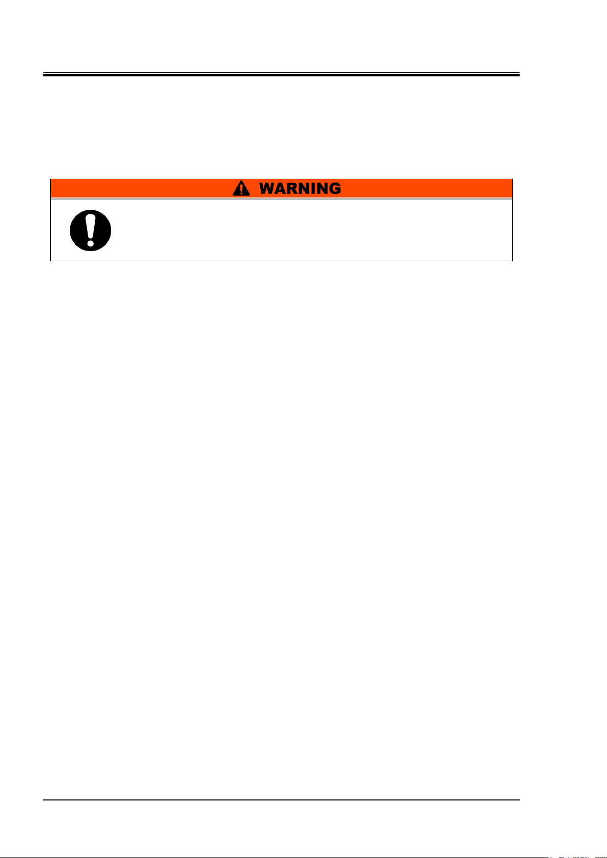
1-8
Follow the following instructions upon operation of this system.
Failure to follow the instructions can lead to personal injury or hazardous
accidents.
Chapter 1 Safety
1.5 Safety Measures
1.5.1 Safety Precautions
While this system is protected by various safety measures including the safety
interlocks, the following basic safety precautions should be observed to assure
further safe operations.
Read and understand this manual thoroughly before operation of this system.
Before operating the system during maintenance, inform all personnel who are
working in the vicinity of the system to alert them of your action.
Use appropriate tools and follow proper procedures.
See “1.5.4 Protective equipment”to wear protective equipment properly.
Refer to your safety manual for emergency evacuation.
Use assistance to carry object over 20 kg.
Check that all parts and screws are returned to the pre-work conditions at the
end of work.
Do not work when intoxicated or feeling ill. Accidents may occur if
disregarded.
Do not remove a panel unless permitted in this manual.
1.5 Safety Measures HRZ Series
1-9
1.5.2 Safety Interlock system
Front panel
Breaker handle
Figure 1-10 Front Panel
Safety Interlock system
The function of the safety interlock system is not only protect personnel by
restricting operation that may cause damage to this system or the facility around it
but also eliminate the danger relating to safety. This system is outfitted with
several interlock functions that are activated when improper operation or hazardous
conditions occur. System operation shall be terminated when a safety interlock is
activated
An alarm message is displayed on the LCD screen when a safety interlock is
activated. See “Chapter 6 Error Message and Troubleshooting” for details on the
alarms and remedies or see section “Troubleshooting” in a separate volume of the
“Service Manual”.
Front panel
System repair may require the removal of the front panel.
The breaker handle operation is available only with the front panel attached.
HRX-OM-I051
Chapter 1 Safety
HRZ Series 1.5 Safety Measures
HRX-OM-I051
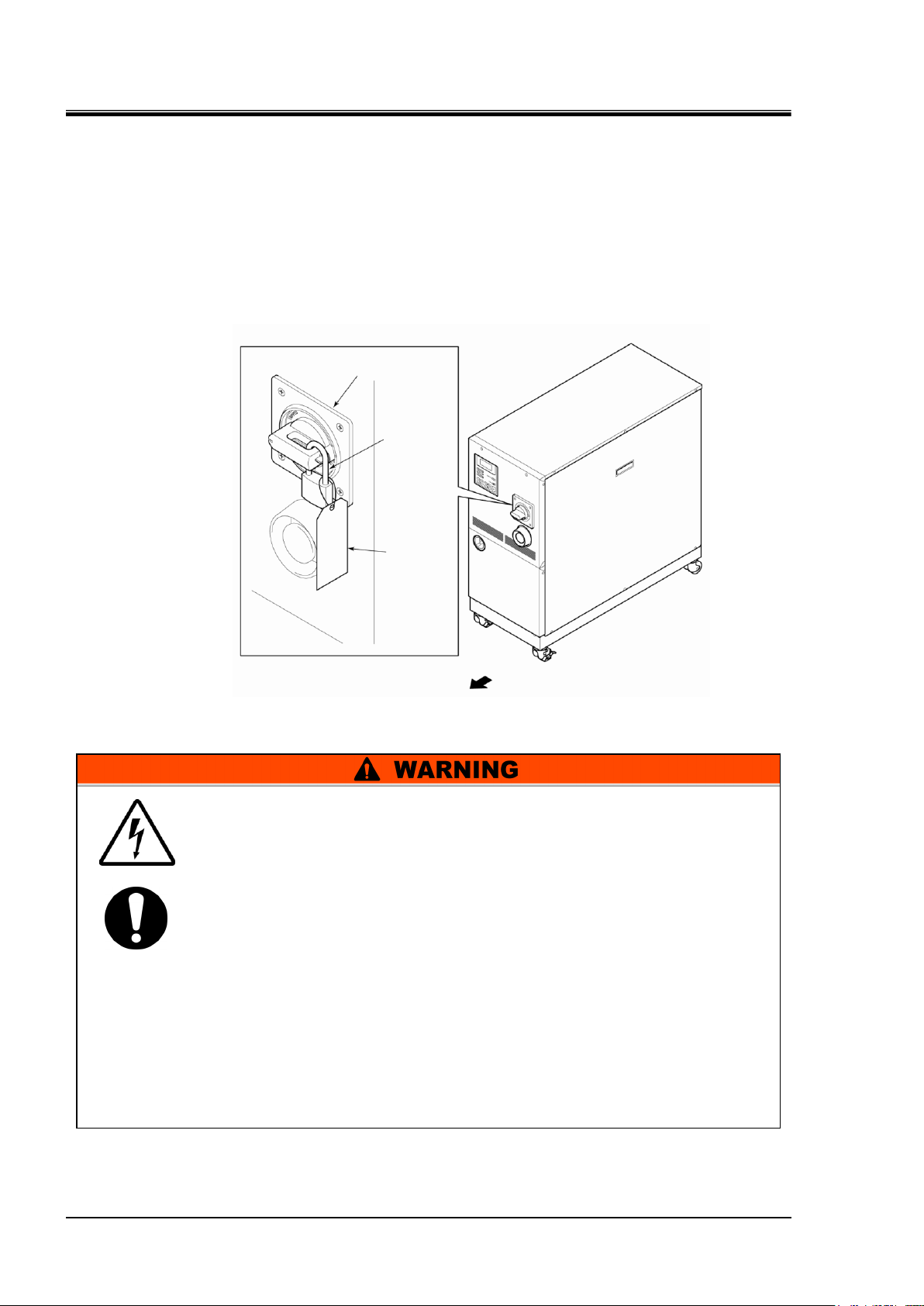
1-10
Main breaker
Padlock
Tag
Front
Figure 1-11 Lockout/Tagout
Those who engage in service of this system should build an awareness of
the importance of lockout. Thorough understanding of the procedures
defined in this manual are required for system service.
Lockout is allowed only when the system come to a full stop.
A supervisor should be appointed to direct all personnel if multiple
workers engage in system service.
The supervisor is to perform lockout based on a full understanding of
overall process conditions.
Not only all personnel but new personnel that engage in service of this
system should build an awareness of the importance of lockout and
obtain thorough understanding of the lockout procedure.
Any personnel working in an area with high voltage should be assigned
with padlocks and tags. The key for the padlock is kept under the
responsibility of the supervisor, and lockout release is performed upon
completion of work.
Chapter 1 Safety
1.5.3 Lockout/Tagout
Summary
Lockout in this system disables the main breaker operation to prevent electric
shocks.
Tagout, to be placed on a locked out main breaker, to prevent improper breaker
operation (ON) conducted by other personnel.
See “ Lockout procedure” in the following pages for practical lockout/tagout.
1.5 Safety Measures HRZ Series
1-11
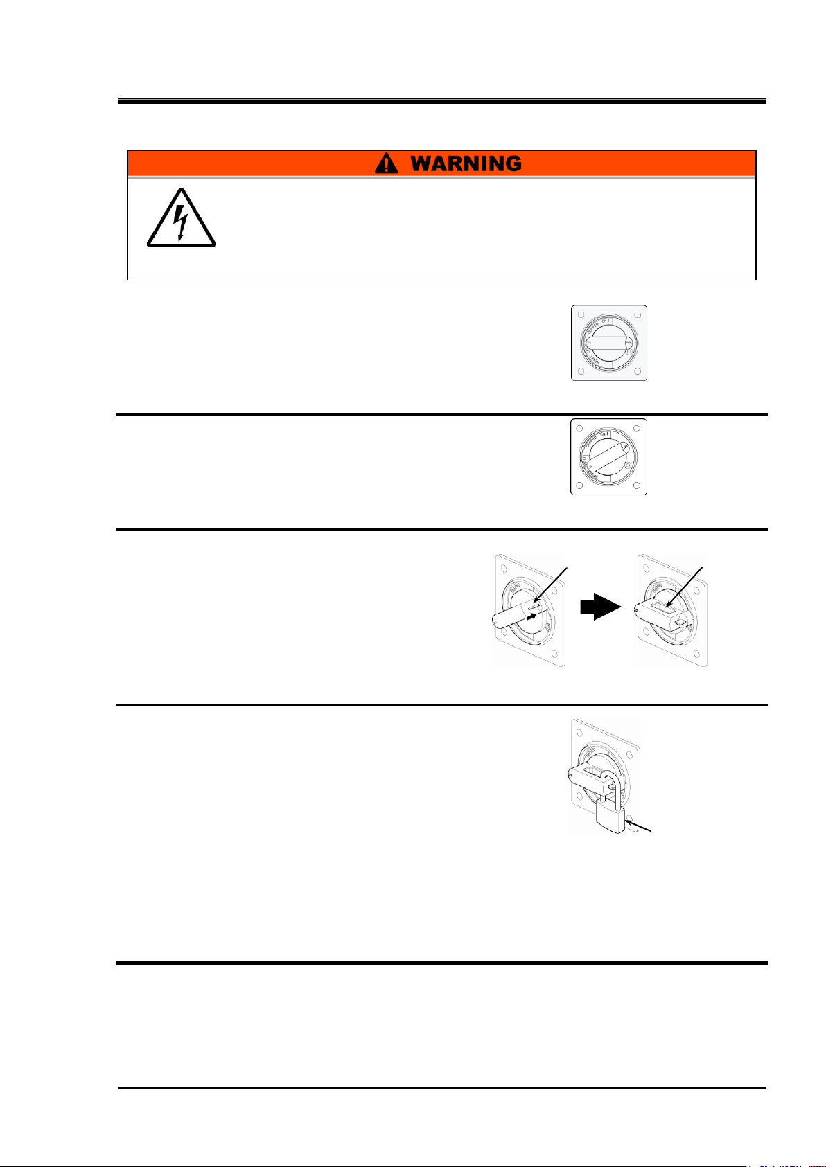
Lockout procedure
Padlock
Lock pushing part
Lock mechanism part
Figure 1-12 Breaker Handle at ‘OFF ’
Figure 1-13 Breaker Handle at ‘RESET’
Figure 1-14 Pushing of Lock Mechanism Part
Figure 1-15 Breaker Lock
All service personnel must observe the restrictions applied during
lockout and are required to perform lockout in accordance with this
procedure. No service personnel is allowed to start, energize, or use
the locked out system.
1. Turn the breaker handle to ‘OFF ’.
HRX-OM-I051
Chapter 1 Safety
2. Turn the breaker handle to ‘RESET’.
Hold the breaker handle with hand.
The handle turns back to ‘OFF ’ if released.
3. Push the lock pushing part of the breaker
handle, and turn the breaker handle to
‘OFF ’.
The lock mechanism part is to remain opened.
4. Lock the lock mechanism part with the
padlock.
Releasing lockout
1. Remove the padlock from the lock mechanism part.
2. Turn the breaker handle to ‘RESET’.
The lock mechanism part is closed.
The handle turns back to ‘OFF ’ if released.
HRZ Series 1.5 Safety Measures

HRX-OM-I051
1-12
Read and understand the relevant operation manual thoroughly prior to use
of protective equipment.
Chapter 1 Safety
1.5.4 Protective equipment
This manual defines protective equipment according to work type.
Wear proper protective equipment as shown below, according to work type.
For system transportation, installation and removal
Protective footwear Protective gloves Hard hat
For handling circulating fluid
Protective footwear Protective gloves Protective mask
Protective apron Protective goggles
For system operation
Protective footwear Protective gloves
1.5 Safety Measures HRZ Series
1-13
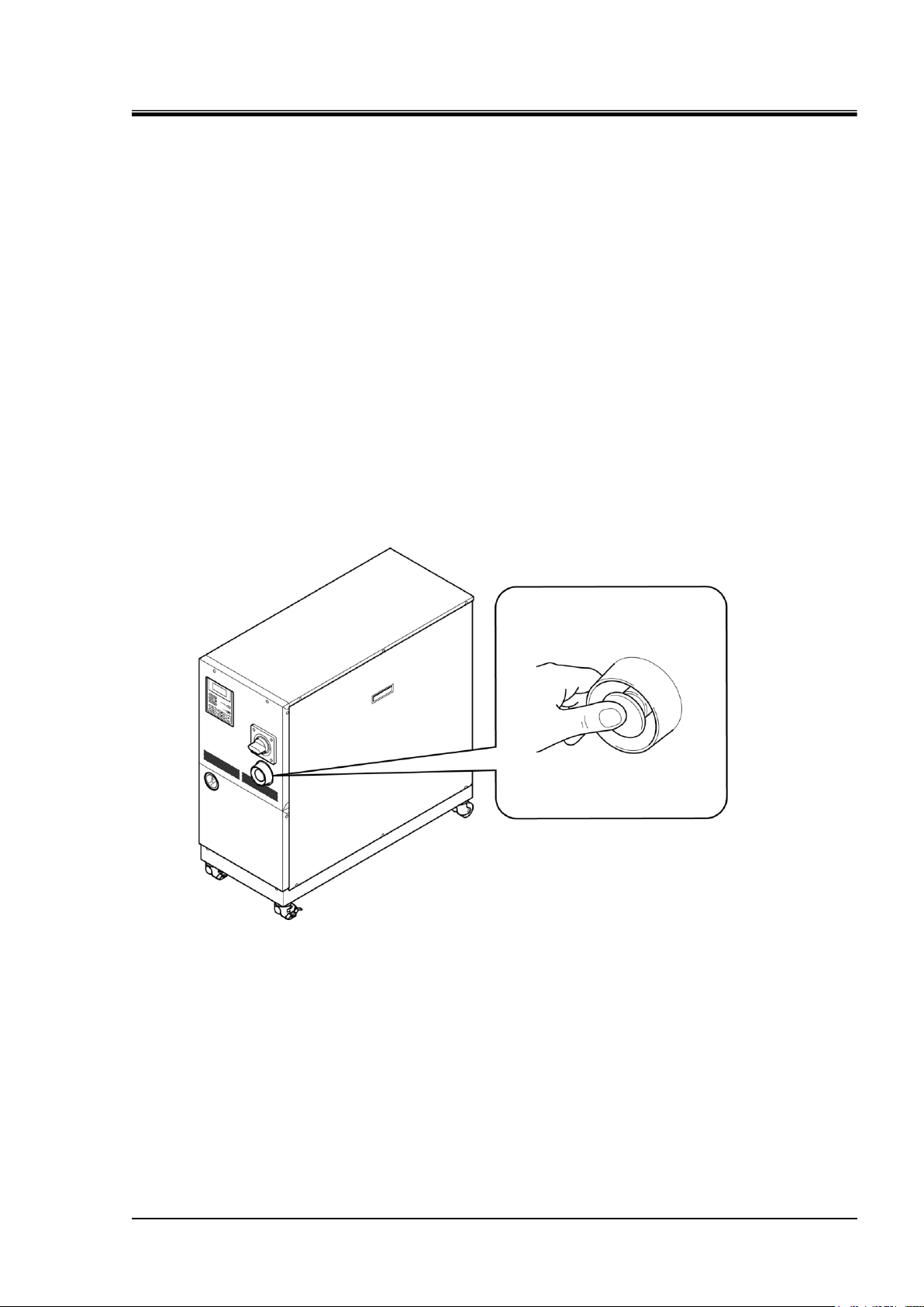
1.6 Emergency Measures
Figure 1-16 Location of Emergency Off [EMO] Switch
1.6.1 Emergency off [EMO] switch
Press the red emergency off [EMO] switch on the front of the system only if the
need to shut off the power arises due to emergency such as natural disaster, fire,
earthquake or personal injury.
The emergency off [EMO] switch is a large, red mushroom-shaped push button
labeled with ‘EMO’ on it. The system comes to a halt if this button is pressed.
When press the emergency off [EMO] switch, the control power for this system is
shut off to bring the system to a stop. The main breaker of this system, however, is
designed not to trip, which enables the motor circuit to remain partially energized.
“8.1.2 Communication specification” in Chapter 8 Appendix on page 8-5 to view
the circuit diagram and see how the EMO switch is interconnected to the system.
Restart of this system is enabled only when this button is reset manually.
Location of emergency off [EMO] switch
HRX-OM-I051
Chapter 1 Safety
HRZ Series 1.6 Emergency Measures
HRX-OM-I051
1-14
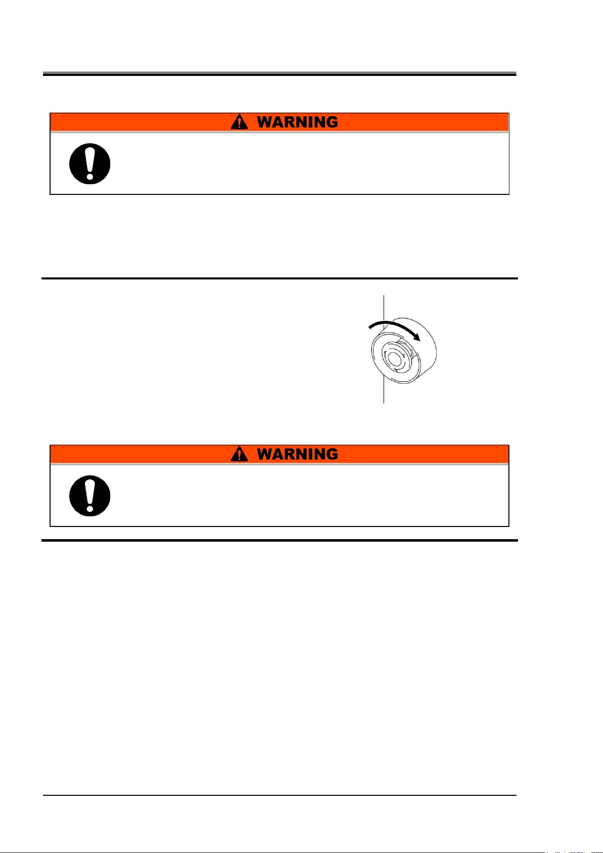
Figure 1-17 Emergency Off [EMO] Switch
No automatic recovery is applied to the emergency off [EMO] switch.
Always eliminate the cause of activating the EMO before resetting.
Potential serious accidents may occur if disregarded.
When the system is in remote mode, the remote mode is retained despite the
power outage. Thus the system operation is to resume as the start signal is
issued from your system.
Chapter 1 Safety
Reset of emergency off [EMO] switch
1. Before restarting, always make sure that the cause of the emergency off condition (The
reason why the EMO switch was activated) has been eliminated from the power supplies,
the system and peripheral equipment.
2. With the cause completely eliminated,
turn the emergency off [EMO] switch
clockwise to reset.
The EMO button returns to its original position.
3. The screen then changes from the “Model Indication screen” to “Status screen 1” as power
is being restored to the system.
1.6 Emergency Measures HRZ Series
1-15
1.7 Waste Disposal
Only service personnel or those who are qualified are allowed to open
the panel of this system.
Do not dispose of the compressor oil as domestic garbage.
Incineration is permitted only at an authorized incinerator.
Disposal of the compressor oil must be in accordance with regulations and
rules of local authorities.
The release of refrigerant into the air is prohibited by law.
Recover the refrigerant with the “refrigerant recovery system”, and
request the specialized waste disposal agency for disposal of the
recovered refrigerant.
Only personnel with proper licensing, who have adequate knowledge and
experiences with not only this system but associated equipment are allowed
to implement the recovery of the refrigerant and compressor oil.
1.7.1 Disposal of refrigerant and compressor oil
HFC- refrigerant and compressor oil are present in this system. When recovering
the refrigerant or compressor oil, the precautions provided below should
thoroughly be read and understood in advance. If you have any questions or
concerns, contact the system supplier.
HRX-OM-I051
Chapter 1 Safety
[Tips]
For the type and quantity of the refrigerant, See “Location of Model Label” on
page 1-7.
HRZ Series 1.7 Waste Disposal
HRX-OM-I051
1-16
Chapter 1 Safety
1.7.2 Circulating fluid disposal
As to the disposal of a circulating fluid (ethylene glycol solution, fluorinated fluid),
consign the specialized industrial waste disposal agency with the contents detailed.
1.7.3 System disposal
As to the disposal of this system, consign the specialized industrial waste disposal
agency in accordance with local laws and regulations.
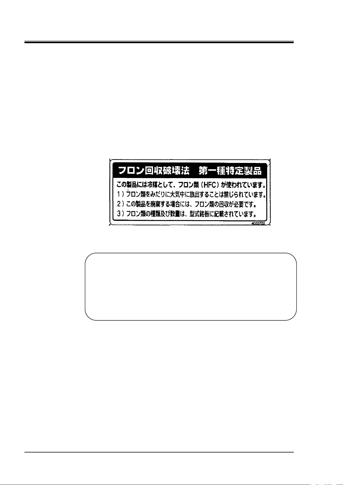
1.7.4 Lavel
Label described below which is attached to the top panel of product is that required
by Japanese law, and the content of this label is applicable in Japan only.
Contents of description of this label is shown as follows.
Fluorocarbon Collection and Destruction Law in Japan
This product uses Fluorocarbon (HFC) as a refrigerant.
1. It is strictly forbidden to emit Fluorocarbon to the atomosphere.
2. When disposing this product, Fluorocarbon must be collected in an appropriate
manner.
3. This kind of Fluorocarbon and the amount used in this product is printed on the
name label.
1.8 Material Safety Data Sheet (MSDS)
Material Safety Data Sheet (MSDS) is supplied separately. Contact the system
supplier if you need the MSDS regarding chemicals used in this system.
For each chemical you purchased, the relevant MSDS is to be obtained under your
responsibility. Keep the MSDS along with this manual in the condition that allows
all personnel to check the contents anytime to gain the understanding of potential
hazards.
1.8 Material Safety Data Sheet (MSDS) HRZ Series
Chapter 2 Name of Each Section
2-1
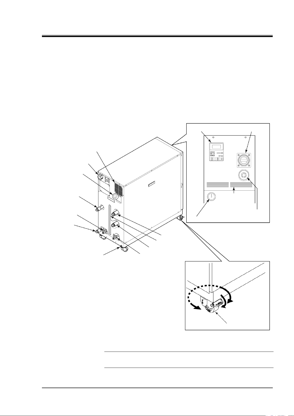
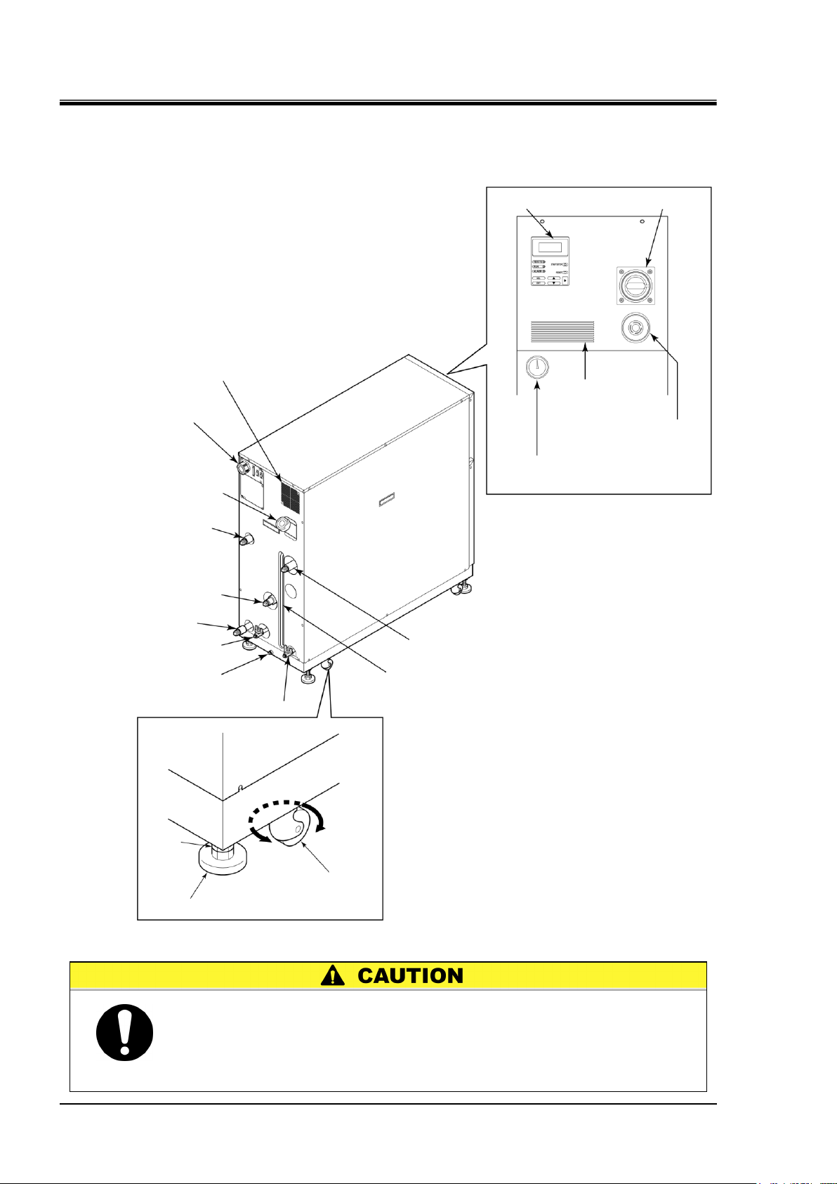
Emergency off [EMO] switch
Refrigerant pressure gauge
Main breaker
Power cable access
Circulating fluid
fill port
Facility water outlet
Circulating fluid
return
Circulating fluid level gauge
Circulating fluid supply
Drain pan port
Facility water inlet
Ventilating fan (exhaust side)
Operation display panel
Sub tank drain port
Main tank drain port
Ventilating hole
(intake side)
Caster w/ brake
Rotates 360°.
Chapter 2 Name of Each Section
2.1 Name of Each Section (1)
HRZ001-L HRZ002-L HRZ004-L
HRZ001-L1 HRZ002-L1 HRZ004-L1
HRZ001-L2 HRZ002-L2 HRZ004-L2 HRZ008-L2
HRZ001-H HRZ002-H HRZ004-H HRZ008-H
HRZ001-H1 HRZ002-H1 HRZ004-H1 HRZ008-H1
HRZ002-W HRZ008-W HRZ002-W1 HRZ008-W1
HRZ010-WS HRZ010-W1S HRZ010-W2S
HRX-OM-I051
HRZ Series 2.1 Name of Each Section (1)
Figure 2-1 Name of Each Section (1)
[Tips]
The front casters (2 pcs.) have built-in brakes. The disengagement of the
brakes is required when transporting the system.
HRX-OM-I051
2-2
When transporting the system with the casters, raise the adjustable feet
(4 pcs.) to the highest position and lock them with the nuts.
The adjustable foot at the lower position may cause damage to this
system and personal injury through contact with the floor or steps
during system transport.
Operation display panel
Refrigerant pressure gauge
Ventilating hole
(intake side)
Ventilating fan (exhaust side)
Power cable access
Circulating fluid fill port
Facility water outlet
Circulating fluid supply
Facility water inlet
Main tank drain port
Drain pan port
Circulating fluid return
Circulating fluid level gauge
Caster
Rotates 360°.
Nut
Main breaker
Emergency off [EMO] switch
Sub tank drain port
Adjustable foot
Chapter 2 Name of Each Section
2.2 Name of Each Section (2)
HRZ008-L HRZ008-L1
Figure 2-2 Name of Each Section (2)
2.2 Name of Each Section (2) HRZ Series
HRX-OM-I051
3-1
Proper procedure must be followed when using this system.
Exercise caution to assure personnel safety during the installation, operation,
maintenance, and inspection of the system.
Only personnel, who have adequate knowledge and experiences with not only
this system but associated equipment are allowed to perform transport,
installation, and maintenance involving potential hazardous task.
For transporting with the forklift, be sure to insert the fork into a
designated position, referring to “3.1.1 Transporting with forklift” on
page 3-2.
Do not set this system on its side during transportation. Oil in the
compressor drains into the refrigerant pipe, which causes lubricant
shortages leading to damage to the compressor.
Drain the remaining fluid out of the pipe as much as possible.
The remaining fluid may spill if disregarded.
Exercise caution not to damage the panel and piping with the forklift
when transporting the system.
Chapter 3 Transporting and Installation
Chapter 3 Transporting and Installation
3.1 Transporting
This system is heavy, which poses potential danger at transportation.
When transporting this system, the following safety precautions should be
observed to prevent system damage and breakdown.
HRZ Series 3.1 Transporting

HRX-OM-I051
3-2
Figure 3-1 Transport with Forklift
This system is heavy, and requires a forklift to safely move it.
Forklift insertion positions are on either left or right side of this system.
Always insert the forks all the way through. Becareful not to hit the
casters and adjustable feet.
Do not set this system on its side for transportation. Potential damage to
this system carrying danger of personnel injury if disregarded.
Do not insert the fork from the back as well as front.
Rear
Front
Forklift insertion side
Forklift insertion side
Chapter 3 Transporting and Installation
3.1.1 Transporting with forklift
3.1 Transporting HRZ Series
3-3
3.1.2 Transporting with caster
This system is heavy, which requires assistance for this work.
Exercise caution and look out for sloped surfaces such as ramps, etc.
Do not grab piping on the back of this system or panel handles when
transporting with the casters.
Potential damage to piping and panels may occur if disregarded.
System installation should be kept from areas with the potential of
flammable gas leak. Ignition may occur if leaked gas is collected
around the system.
This system is NOT designed for outside use.
Potential electric shock, fire and system damage may occur if exposed
to rain, water and dust.
This system is to be installed on a level floor that can withstand the
weight of this system. Potential water leak and personal injury due to
system tipping over may occur if disregarded.
3.2 Installation
HRX-OM-I051
Chapter 3 Transporting and Installation
HRZ Series 3.2 Installation

HRX-OM-I051
3-4
Chapter 3 Transporting and Installation
3.2.1 Installation conditions
System installation is not allowed outside or in the conditions described below.
Potential system malfunction and damage may occur if disregarded.
Clean room specifications are not applied to this unit. The pump and ventilating
fan installed in this unit generate particles.
Location that is exposed to water vapor, salt water, and oil
Location that is exposed to dust and powder
Location that is exposed to corrosive gas, solvent, and flammable gas
Location that is exposed to direct sun light or radiant heat
Location where ambient temperature is out of the following range:
In operation 10 to 35°C
In storage 0 to 50°C (with no water or circulating fluid in piping)
Location where relative humidity is out of the following range:
In operation 30 to 70%
In storage 15 to 85%
Location that is subjected to abrupt changes in temperature
Location that is subjected to intense electromagnetic noise (intense electric field,
intense magnetic field, or surges)
Location that is subjected to static electricity, or condition that discharges static
electricity to the system
Location that is subjected to strong high frequencies
Location that is subjected to potential lightning damage
Location with altitudes of 1000m or higher
Location that is affected by strong vibrations or impacts
Condition that applies external force or weight causing the system deformation
Condition with no adequate space for maintenance as required in the installation
site.
3.2 Installation HRZ Series
Chapter 3 Transporting and Installation
3-5
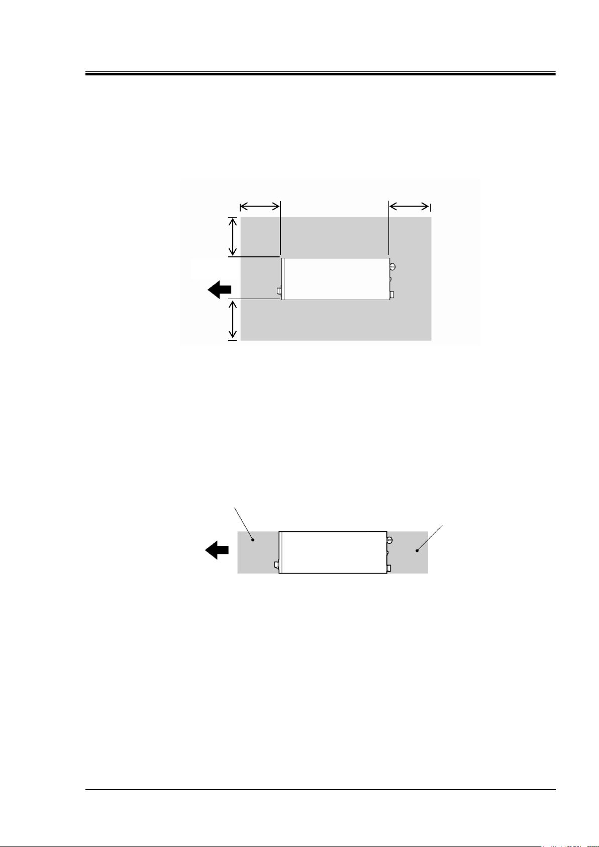
Daily inspection area
Operation area
Front
Figure 3-3 Installation Location
Front
800mm
800mm
800mm
800mm
Figure 3-2 Recommended Installation Location
3.2.2 Installation location and maintenance work area
This system does not have ventilating hole on the both right and left sides. Although this can be
installed directly contacting to walls or devices, installation with maintenance space is
recommended. (See “Figure 3-2)
HRX-OM-I051
To save space, this system can be installed to allow access only in front and back for daily operation
and inspection. For maintenance and repair work, additional access space is required for the left and
right side of the system. We recommend a separate repair area, without taking space from
installation site, to accommodate the needed extra space.
HRZ Series 3.2 Installation
HRX-OM-I051
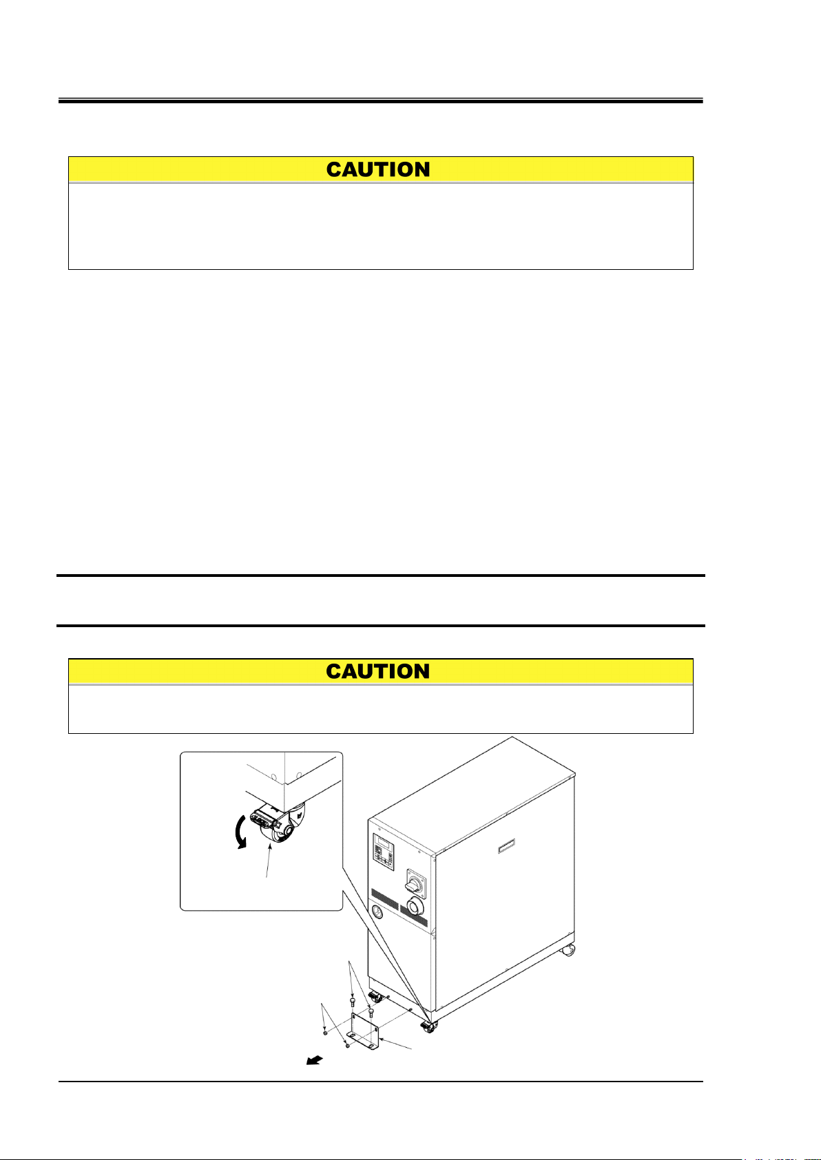
3-6
Anti-seismic bracket is an optional part (except for HRZ008-L, HRZ008-L1), which is
required for the installation of this system (HRZ-TK002).
Preparation of anchor bolts suitable for floor material is your responsibility. M8-anchor
bolts (8 pcs.) are required for HRZ008-L and HRZ008-L1, and M12-anchor bolts (4 pcs.)
for other models. See “Appendix 8.5 BAND/READY function”
Figure 3-4 Anti-seismic Bracket Attachment
Drain pan port is assigned to the bottom on the back of this system. Exercise
caution not to damage the dain pan port when attaching the anti-seismic bracket.
Front
Anti-seismic bracket (optional)
HRZ-TK002
M8 nut (2 pcs.)
(Accessory for anti-seismic
bracket)
Caster w/ brake
(2 pcs. on the front)
Brake lever
M12 anchor bolt
Chapter 3 Transporting and Installation
3.3 Procedure for Installation
3.3.1 Installation
System installation should be on a vibration-free stable level plane.
See “Appendix 8.2 Outer Dimensions” in Chapter 8 on page 8-14 for the
dimensions of this system.
3.3.2 Procedure for system securing (1)
HRZ001-L HRZ002-L HRZ004-L
HRZ001-L1 HRZ002-L1 HRZ004-L1
HRZ001-L2 HRZ002-L2 HRZ004-L2 HRZ008-L2
HRZ001-H HRZ002-H HRZ004-H HRZ008-H
HRZ001-H1 HRZ002-H1 HRZ004-H1 HRZ008-H1
HRZ002-W HRZ008-W HRZ002-W1 HRZ008-W1
HRZ010-WS HRZ010-W1S HRZ010-W2S
1. Transfer this system to the installation site.
2. Lock the brakes on casters (2 pcs. on the front).
3. Using a13-mm open end wrench, attach the anti-seismic brackets to the front and back.
3.3 Procedure for Installation HRZ Series
 Loading...