

Page 1
HRX-OM-K018-B
HRW***-* -Y
1
2
DI control kit (optional)
Operation Manual
Applicable model: Series HRW
(Thermo Chiller)
Introduction
Thank you very much for purchasing DI control kit for our Thermo Chiller, Series HRW.
This manual is for operators who have enough knowledge for general industrial equipment and devices, and also
thoroughly understand assembling, handling, and maintenance of them. Before assembling, handling, and
maintenance, read and understand this manual and the one for Thermo Chiller, Series HRW carefully.
Installing of accessories has to be performed by a customer according to this manual.
Refer to the operation manual for Thermo Chiller for warranty.
This manual is subject to change without prior notice.
Summary of option
- It is possible to control the electric resistance of circulating fluid as you like by using an ion exchange resin filter
(hereafter DI filter) and electric resistance meter (hereafter DI sensor).
- DI filter is not attached. Purchase our HRZ-DF001 separately if you need. If the DI filter is used at temperature out of
the range, 20 to 40degC, also purchase a thermal insulator, HRZ-DF002, to prevent frostbite and a burn.
Safety instruction
- Understand the meaning of the following signs before reading the body of this manual, and keep the instruction.
Indication Meaning
Warning
!
Caution
!
- Before using, understand the specification range thoroughly.
This product is designed as an option for Thermo Chiller, Series HRW. Do not use this product for the other
purpose, or outside of the specification range.
- Understand the contents of this manual and the working procedure thoroughly.
Understand this manual and the one for Thermo Chiller (Document no: HRX-OM-K003) thoroughly. Keep
this operation manual so that you can refer whenever necessary.
- Do not perform ins t alla t i o n work wh il e power i s o n .
Perform lock-out and tag-out of the power securely. Otherwise, Thermo Chiller may operate unexpectedly.
- Perform installation work with o u t any c i r c ulat i ng f l uid i n Th er mo C hiller.
Perform the work before supplying circulating fluid in or after exhausting all the circulating fluid from
Thermo Chiller. The circulating fluid shoud be exhausted after the fluid gets to be ambient temperature.
Otherwise, an operator may get a burn or frostbite.
- Do not disassemble or modify.
Otherwise it may cause leakage and operation failure.
- Confirm there is no leakage or condensation after installation.
Confirm there is no leakage or condensation with Thermo Chiller operated. If leakage is found, stop Thermo
Chiller immediately.
Things to prepare
Spanner (width across flats: (1) 9/16 inch, (2) 1/2 inch, (3) 5/8 inch, (4) 11/16 inch )
Operator error could result in serious injury or loss of life.
Operator error could result in injury or equipment damage.
Warning
!
Caution
!
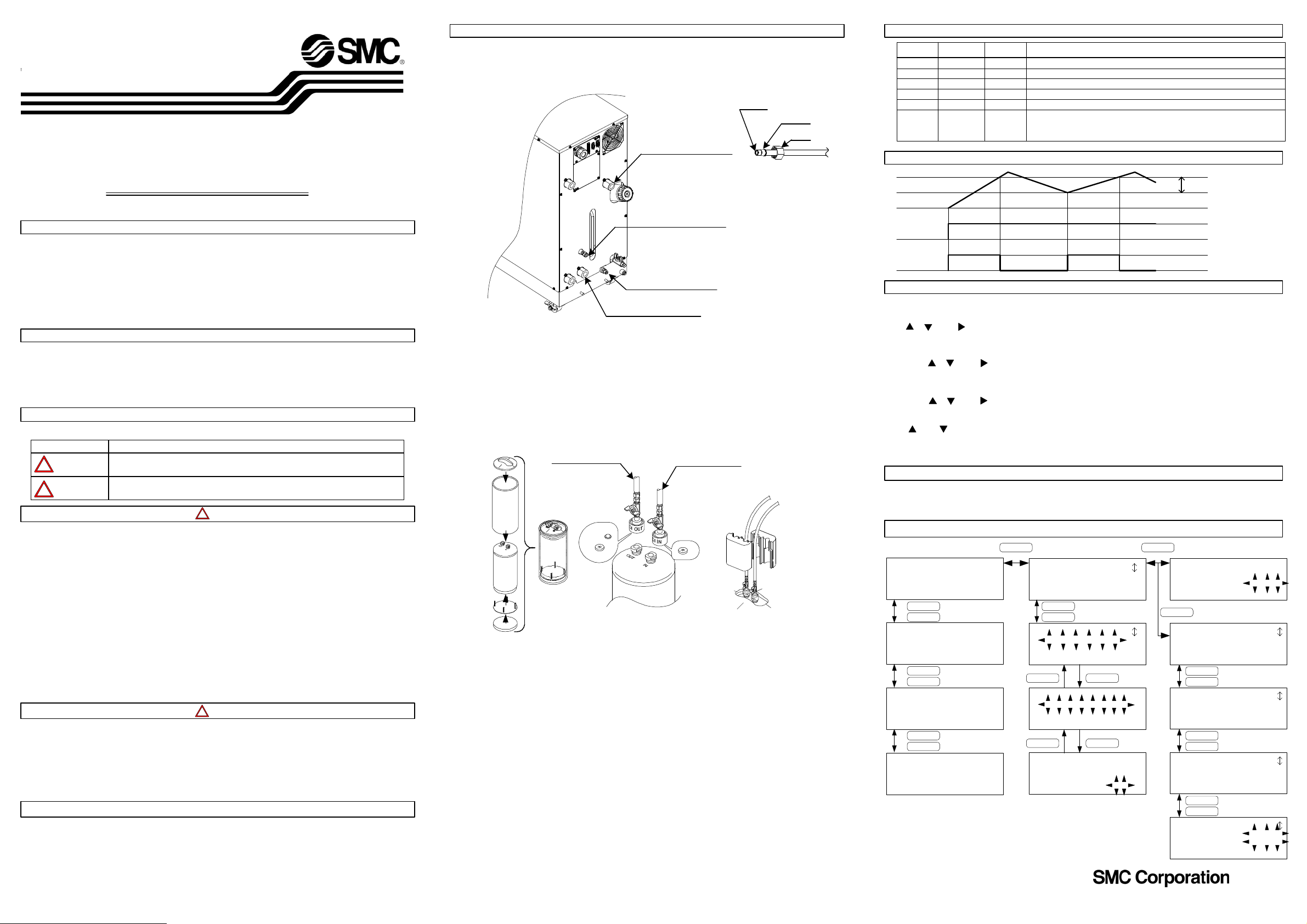
Accessory installation
Introduction
Refer to the accessory list on the back, and confirm the number of the accessory. In addition, confirm the
model no. plate on the body has "-Y" indication, which is symbol for this option.
Insert
Ferrule
Nut
Circulating fluid Supply
DI circuit Return
(DI tube connecting port for OUT)
DI circuit Supply
(DI tube connecting port for IN)
Circulating fluid Return
Fig. 1
Procedure 1
Confirm that a nut, a ferrule, and an insert are installed at the end of the DI tube for IN (Fig. 1). Insert the DI tube
for IN to the end of the DI circuit Supply, and tighten the nut by hand. At that time, use two spanners, (1) and (2),
not to rotate the self-align fitting. Turn the hand-tightened nut by 1/4 rotation.
Procedure 2
Confirm that a nut, a ferrule, and a insert are installed at the end of the DI tube for OUT (Fig. 1). Insert the DI tube
for OUT to the end of the DI circuit RETURN, and tighten the nut by hand. At that time, use two spanners, (3) and
(4), not to rotate the self-align fitting. Turn the hand-tightened nut by 1/4 rotation.
DI tube for OUT
Fig. 2
Fig. 3
Procedure 3
Mount a therml insulator for DI filter as shown at Fig. 2, and set it in the drain pan (only for the customers who purchased
it).
Procedure 4
Supply circulating fluid from IN side of the DI filter to exhaust air. Continue to supply until OUT side is filled
with circulating fluid.
Procedure 5
Connect the DI tube for OUT and DI tube for IN to OUT side and IN side of the DI filter respectively. As the DI
tube has a strainer and a packing at the DI filter connection part, be careful not to drop them (Refer to Fig. 3).
Procedure 6
Perform trial operation in accordance with Thermo Chiller operation manual, HRX-OM-K003. Initially, the DI
filter has water. If ethylene glycol solvent is used, the concentration may be decreased. Confirm the concentration
after the trial operation. The proper concentration of ethylene glycol is 60%. If no leakage is found, install a
insulator to a ball valve connected to the DI tube, and fix it with a band (Refer to Fig. 4).
DI tube for IN
Fig. 4
Indication on the operation display panel
-
When shipped
from factory
-
0.5Mohm
No
-
0.3Mohm
DI level at the circulating fluid Supply, measured by the DI sensor
Setting for DI level
Accumulated ON time of the solenoid valve (accumulated fluid-running time through the DI filter)
Status of the solenoid valve (ON=open, OFF=closed)
Indication
Set range
DI PV
DI SP
DI ACC
DI SV
DI HYS Refer to "DI HYS" below.
0 to 20Mohm
Yes/No
ON/OFF
0 to 0.9Mohm
When the DI level gets lower than the setting, an indication "DI LOW
LOW DI
0 to 20Mohm
0.0Mohm
LEVEL WRN" will be shown, and a buzzer will be given off.
If the setting has "0.0", no alarm will be given off.
Description
DI HYS
DI SP
DI LEVEL
Operation
condition
Solenoid
valve
DI HYS
Operation
Stop
ON(open)
OFF(closed)
Operation with operation display panel
(1) Setting of DI SP
Plate a cursor on "DI SP" on the screen "Setting", and press [ENT] key. Set the value to the one you desire
with [ ], [ ], and [ ] keys. After setting the value, press [ENT] key.
(2) Setting of DI HYS
Set a cursor on "DI HYS" on the screen "Initial setting 4", and press [ENT] key. Set the value to the one you
desire with [ ], [ ], and [ ] keys. After setting the value, press [ENT] key.
(3) Setting of DI level lowering alarm (LOW DI)
Set a cursor on "LOW DI" on the screen "Initial setting 4", and press [ENT] key. Set the value to the one you
desire with [ ], [ ], and [ ] keys. After setting the value, press [ENT] key.
(4) Reset of DI ACC
Press [ ] and [ ] keys while the screen "DI ACC reset" is shown, and select [YES]. Then, press [ENT] key.
(5) Status of DI circuit
You can confirm it on the screen "Status 3".
External communincation
Only DI PV can be output by external communication (serial RS-485). Refer to the separate manual,
"Communication Specification/ HRX-PS-K005", for detail. If analog communication (option) is used
refer to "Communication Specification/HRX-PS-K018".
Operation panel sequence
Thermo Chiller
HRW□□□-□□-Y
Rev.□□□
SMC Co.
Model indication Menu 1
▲
▼
TEMP PV 23.8℃
FLOW PV 20.0LPM
PRESS 0.85MPa
R.TEMP 23.8℃
▲
▼
TEMP PV 23.8℃
TEMP SV 25.0℃
OFFSET 0.0℃
OFFSET: OFF
▲
▼
DI PV 1.0MΩ
DI SP 0.5MΩ
DI ACC 0h
DI SV OFF
Status 1
Status 2
Status 3
SEL
<MENU>
1.SETTING
2.REMOTE/LOCAL
3.INITIAL SET
▲
▼
<MENU>
4.MAINTENANCE
5.OPTION
SEL ENT
<MAINTENANCE>
1.DI ACC RESET
2.VALUE OPEN
SEL ENT
<DI ACC RESET>
DI ACC 0h
DATA RESET? No
Menu 2
Maintenance
DI ACC reset
SEL
<SETTING>
TEMP SP 25.0℃
DI SP 0.5MΩ
SEL
<INITIAL SET>
OFFSET 0.0℃
OFFSET: OFF
HIGH TEMP 93℃
▲
▼
<INITIAL SET>
LOW FLOW 0LPM
FLOW UNIT LPM
PRESS UNIT MPa
▲
▼
<INITIAL SET>
SLAVE ADRS. 1CH
OUT: N/A
E OUT: N/A
▲
▼
<INITIAL SET>
DI HYS 0.3MΩ
LOW DI 0.0MΩ
F.LOW TEMP 10℃
Initial setting 1
Initial setting 2
Initial setting 3
Initial setting 4
Setting
© 2006 SMC CORPORATION All Rights Reserved
1
2
3
Page 2
HRW***-* -Y
2
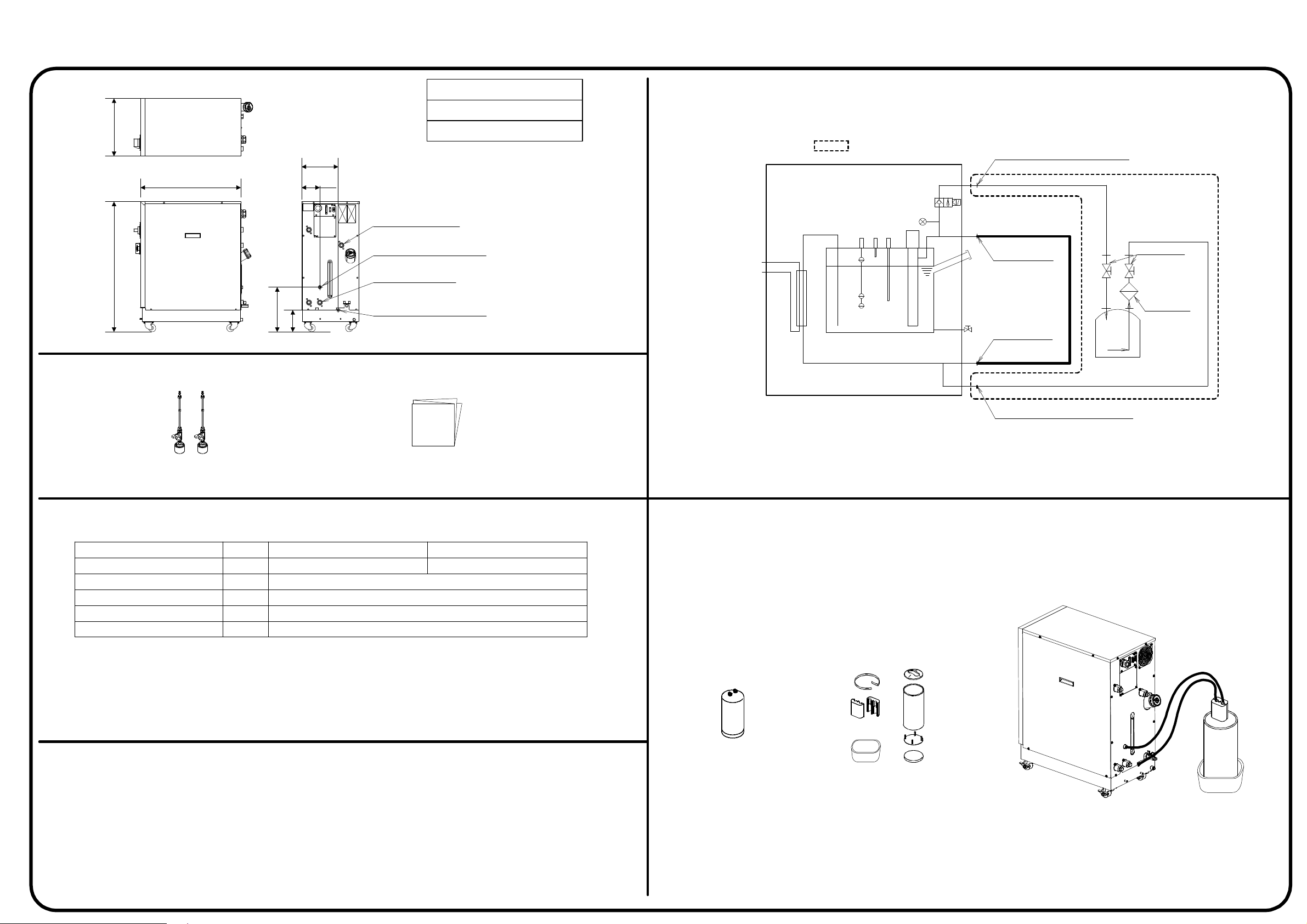
Material for DI control kit (optional)
1
(380)(860)
Accessories
(665)
Applicable model
HRW***-* -Y
HRW***-* S-Y
(242)
(120)
Circulating fluid supply
(Rc3/4)
DI circuit return
(3/8 self-align fitting/with plug)
Circulating fluid return
(Rc3/4)
(294)
(143)
DI circuit supply
(3/8 self-align fitting/with plug)
1
2
1
2
Dimensional tolerance for each: 10mm
Flowchart
Facility water
:Option
Soleno id v a lv e
DI sensor
Circulating fluid tank in Thermo Chiller
Thermo Chiller DI circuit su p p ly
Piping for customer's syst em
Circurating
fluid supply
(Rc3/4)
Circulating fluid
return
(Rc3/4)
Ball v a lve
(IN/OUT)
Strainer
DI filte r
(not attached)
DI tube for IN/OUT
(with a insulator) x 1pc for each
Operation manual (this document)
[document no:HRX-OM-K018]Jpn x 1 copy, Eng x 1 copy
Specification Table
Applicable model
Available circulating fluid for DI circuit
DI level indication range
DI level setting range
Control solenoid valve hysteresis
DI level lowering alarm setting range
*1: DI filter (Part no.: HRZ-DF001) is necessary to control DI level. This optional product does not have DI filter,so
purchase it separately. If this product is used out of the range of 20 to 40degC, also purchase a thermal insulat or
for DI filter (our part no.: HRX-DF002) to avoid frostbite and burn.
*2: Temperature correction is not applied to the DI level indication value.
Note: Temperature stability at supply of circulating fluid in the Thermo Chiller could be out of +/-0.3degC depending
on DI filter replacement and operating condition s.
-
MΩ・cm
MΩ・cm
MΩ・cm
MΩ・cm
HRW***-H1-Y/HRW***-H1S-Y HRW***-H2-Y/HRW***-H2S-Y
60% Ethylene glycol solvent
0~20*
0~20*
2
1
DI water
0~0.9
0~20
*This option doe s not h a ve DI filter.
For details, please refer to specification table and notes.
DI filter/ Thermal insulator for DI filter
(This option does not have DI filter and Thermal insulator.)
Thermo Chiller DI circ uit R e tur n
DI circuit
Note
1.This product is designed as an option for Thermo chiller, Series HRW. Do not use this product for the other purpose, or outsi de
of the specification range.
2.Installation of accessories has to be performed by a customer according to the operation manual.
3.Supply circulating fluid from IN side of the DI filter to exhaust air. Continue to supply unitl OUT side is filled with circulati ng
fluid.
4.The DI filter has water inside. If ethylene glycol solvent is used, the concentration may be decreased.
Confirm the concentration after the trial operation. The proper concentration of ethylene glycol is 60 %.
DI filter
Part No.:HRZ-DF001
Thermal insulator for DI filter
Part No.:HRZ-DF002
DI filter/ insulator for DI filter
mounted condition
 Loading...