

SMC Networks HRSH200-A*-20 Series, HRSH250-A*-20 Series, HRSH250-A*-40 Series, HRSH150-A*-20-*, HRSH150-A*-20 Series Operation Manual
Page 1

HRX-OM-Q026-B
1
st
edition: Dec. 2012
Rev.B: Mar.2013
Operation Manual
Installation・Operation
Original Instructions
Thermo chiller
HRSH series
HRSH150-A∗-20-
∗
HRSH200-A∗-20-
∗
HRSH250-A∗-20-
∗
HRSH250-A∗-40-
∗
Keep this manual available whenever necessary
© 2013 SMC CORPORATION All Rights Reserved
Page 2

To the users
Thank you for purchasing SMC’s Thermo chiller (hereinafter referred to as the “product”).
For safety and long life of the product, be sure to read this operation manual (hereinafter referred to as the
“manual”) and clearly understand the contents.
• Be sure to read and follow all instructions noted with “Warning” or “Caution” in this manual.
• This manual is intended to explain the installation and operation of the product. Only people who
understand the basic operation of the product through this manual or who perform installation and
operation of or have basic knowledge about industrial machines are allowed to work on the product.
• This manual and other documents attached to the product do not constitute a contract, and will not
affect any existing agreements or commitments.
• It is strictly prohibited to copy this manual entirely or partially for the use by a third party without prior
permission from SMC.
Note: This manual is subject to possible change without prior notice.
Page 3

HRX-OM-Q026-B
Contents
HRSH Series
Contents
Chapter 1 Safety Instructions .......................................................... 1-1
1.1 Before using the product ..........................................................................................1-1
1.2 Reading the Manual ................................................................................................... 1-1
1.3 Hazards ....................................................................................................................... 1-2
1.3.1 Level of hazards.................................................................................................................. 1-2
1.3.2 Definition of “Serious injury” and “Minor injury”................................................................... 1-2
1.4 Product Label ............................................................................................................. 1-3
1.5 Safety Measures.........................................................................................................1-4
1.5.1 Safety Instructions for Use .................................................................................................. 1-4
1.5.2 Personal Protective Equipment........................................................................................... 1-4
1.6 Emergency Measures ................................................................................................ 1-5
1.7 Waste disposal...........................................................................................................1-5
1.7.1 Disposal of refrigerant and compressor oil.......................................................................... 1-5
1.7.2 Disposal of product.............................................................................................................. 1-5
1.8 Material Safety Data Sheet (MSDS) ..........................................................................1-6
Chapter 2 Name and Function of Parts............................................. 2-1
2.1 Model number of product.......................................................................................... 2-1
2.2 Name and Function of Parts .....................................................................................2-2
2.3 Function of Parts........................................................................................................2-3
2.4 Operation display panel ............................................................................................2-4
Chapter 3 Transport and Setting Up ................................................. 3-1
3.1 Transport ....................................................................................................................3-1
3.1.1 Moving by forklift and slinging ............................................................................................. 3-2
3.1.2 Moving by casters ...............................................................................................................3-3
3.2 Installation .................................................................................................................. 3-4
3.2.1 Environment ........................................................................................................................ 3-4
3.2.2 Location............................................................................................................................... 3-6
3.2.3 Installation and Maintenance Space ................................................................................... 3-7
3.3 Installation .................................................................................................................. 3-8
3.3.1 Installation ........................................................................................................................... 3-8
3.3.2 Electrical wiring ................................................................................................................. 3-10
3.3.3 Preparation and wiring of power supply cable ...................................................................3-11
3.3.4 Contact input/output communicatin wiring ........................................................................ 3-15
3.3.5 Wiring of Run/stop signal input・Remote signal input........................................................ 3-15
3.3.6 Wiring of external switch signal input................................................................................ 3-18
3.3.7 Wiring of operation signal output and alarm signal output................................................ 3-21
3.3.8 RS-485 Communication wiring.......................................................................................... 3-22
3.3.9 RS-232C Communication wiring ....................................................................................... 3-23
3.4 Piping ........................................................................................................................ 3-24
Page 4

HRX-OM-Q026-B
Contents
HRSH Series
3.5 Fill of circulating fluid..............................................................................................3-27
3.5.1 Auto fluid-fill function..........................................................................................................3-27
3.5.2 Fill of fluid without using auto fluid-fill function ..................................................................3-29
3.5.3 For option K [Fluid fill port]................................................................................................. 3-31
Chapter 4 Starting the Product.......................................................... 4-1
4.1 Before Starting........................................................................................................... 4-1
4.2 Preparation for Start ..................................................................................................4-2
4.2.1 Power supply .......................................................................................................................4-2
4.2.2 For the option B [Earth leakage breaker].............................................................................4-2
4.2.3 For HRSH∗∗∗-A∗-40-∗ ......................................................................................................... 4-3
4.2.4 Setting of circulating fluid temperature ................................................................................4-3
4.2.5 Setting of pump operation mode .........................................................................................4-3
4.3 Preparation of circulating fluid.................................................................................4-4
4.4 Starting and Stopping................................................................................................4-7
4.4.1 Starting the product..............................................................................................................4-7
4.4.2 Stopping the product............................................................................................................4-8
4.5 Check items after starting.........................................................................................4-9
4.6 Adjustment of Circulating Fluid flow rate................................................................ 4-9
Chapter 5 Display and setting of various functions........................ 5-1
5.1 Function...................................................................................................................... 5-2
5.1.1 Key operations.....................................................................................................................5-2
5.1.2 List of parameters ................................................................................................................5-4
5.2 Main screen ................................................................................................................5-7
5.2.1 Main screen ......................................................................................................................... 5-7
5.2.2 Display on the main screen .................................................................................................5-7
5.3 Alarm display menu................................................................................................... 5-8
5.3.1 Alarm display menu .............................................................................................................5-8
5.3.2 Content of display of alarm display menu............................................................................ 5-8
5.4 Inspection monitor menu .......................................................................................... 5-9
5.4.1 Inspection monitor menu .....................................................................................................5-9
5.4.2 Checking of the Inspection monitor menu ........................................................................... 5-9
5.5 Key-lock.................................................................................................................... 5-13
5.5.1 Key-lock ............................................................................................................................. 5-13
5.5.2 Key-lock setting / checking ................................................................................................5-14
5.6 Run timer, stop timer function................................................................................ 5-15
5.6.1 Run timer and stop timer function...................................................................................... 5-15
5.6.2 Setting and checking of Run timer and stop timer function...............................................5-17
5.7 Ready completion (TEMP READY) signal.............................................................. 5-19
5.7.1 Ready completion (TEMP READY) signal.........................................................................5-19
5.7.2 Ready completion (TEMP READY) signal setting / checking............................................5-20
Page 5

HRX-OM-Q026-B
Contents
HRSH Series
5.8 Offset function .........................................................................................................5-22
5.8.1 Offset function ................................................................................................................... 5-22
5.8.2 Offset function setting and checking ................................................................................. 5-24
5.9 Function to recover from power failure ................................................................. 5-26
5.9.1 Function to recover from power failure.............................................................................. 5-26
5.9.2 Function to recover from power failure setting and checking........................................... 5-27
5.10 Anti-freezing function..............................................................................................5-28
5.10.1 Anti-freezing function......................................................................................................... 5-28
5.10.2 Anti-freezing function setting and checking....................................................................... 5-29
5.11 Key click sound setting...........................................................................................5-30
5.11.1 Key click sound setting...................................................................................................... 5-30
5.11.2 Key click sound setting and checking ............................................................................... 5-30
5.12 Temperature unit switching ....................................................................................5-31
5.12.1 Temperature unit switching ............................................................................................... 5-31
5.12.2 Temperature unit switching setting and checking............................................................. 5-31
5.13 Pressure unit switching ..........................................................................................5-32
5.13.1 Pressure unit switching ..................................................................................................... 5-32
5.13.2 Pressure unit switching setting and checking .................................................................. 5-32
5.14 Data reset function...................................................................................................5-33
5.14.1 Data reset function ............................................................................................................ 5-33
5.14.2 Method of resetting data reset function............................................................................. 5-33
5.15 Accumulated time reset function ...........................................................................5-34
5.15.1 Accumulated time reset function ....................................................................................... 5-34
5.15.2 Method of resetting accumulated time reset function ....................................................... 5-34
5.16 Pump operation mode function..............................................................................5-37
5.16.1 Pump operation mode....................................................................................................... 5-37
5.16.2 How to check the pump operation mode and value setting .............................................. 5-37
5.17 Warming up function ............................................................................................... 5-40
5.17.1 Warming up function ......................................................................................................... 5-40
5.17.2 Warming up function setting and checking ....................................................................... 5-41
5.18 Anti-snow coverage function.................................................................................. 5-43
5.18.1 Anti-snow coverage function ............................................................................................. 5-43
5.18.2 Anti-snow coverage function setting and checking ........................................................... 5-44
5.19 Alarm buzzer sound setting....................................................................................5-45
5.19.1 Alarm buzzer sound setting............................................................................................... 5-45
5.19.2 Alarm buzzer sound setting and checking........................................................................ 5-45
5.20 Alarm customizing function....................................................................................5-46
5.20.1 Alarm customizing function ............................................................................................... 5-46
5.20.2 Alarm customize function setting and checking ................................................................ 5-50
5.20.3 Setting of temperature alarm monitoring method and alarm generation timing................ 5-61
Page 6

HRX-OM-Q026-B
Contents
HRSH Series
5.21 Communication function......................................................................................... 5-67
5.21.1 Communication function ....................................................................................................5-67
5.21.2 Communication function setting and checking .................................................................. 5-67
Chapter 6 Alarm indication and trouble shooting ........................... 6-1
6.1 Alarm Display............................................................................................................. 6-1
6.2 Alarm buzzer stop...................................................................................................... 6-3
6.3 Troubleshooting.........................................................................................................6-4
6.3.1 Alarm contents, causes and remodies ................................................................................6-4
6.3.2 How to release the fan breaker trip .....................................................................................6-8
6.4 Other Errors..............................................................................................................6-10
Chapter 7 Control, Inspection and Cleaning.................................... 7-1
7.1 Control of Circulating Fluid Quality .........................................................................7-1
7.2 Inspection and Cleaning ...........................................................................................7-2
7.2.1 Daily check ..........................................................................................................................7-2
7.2.2 Monthly check......................................................................................................................7-3
7.2.3 Inspection every 3 months................................................................................................... 7-4
7.2.4 Inspection for winter season................................................................................................7-5
7.3 Consumables .............................................................................................................7-5
7.4 Stop for a Long Time ................................................................................................. 7-6
7.4.1 Discharge of the circulating fluid and facility water.............................................................. 7-6
Chapter 8 Documents......................................................................... 8-1
8.1 Specifications.............................................................................................................8-1
8.1.1 HRSH150/200/250-A∗-20-∗.................................................................................................8-1
8.1.2 HRSH250-A∗-40-∗ ...............................................................................................................8-2
8.1.3 Communication specification............................................................................................... 8-3
8.2 Outline dimensions....................................................................................................8-4
8.3 Flow diagram.............................................................................................................. 8-6
8.3.1 HRSH∗∗∗-A∗-20/40-∗...........................................................................................................8-6
8.4 Cooling capacity ........................................................................................................8-7
8.4.1 HRSH150-A∗-20-∗ ...............................................................................................................8-7
8.4.2 HRSH200-A∗-20-∗ ...............................................................................................................8-7
8.4.3 HRSH250-A∗-20/40-∗ .......................................................................................................8-8
8.5 Pump capacity............................................................................................................8-8
8.5.1 HRSH150/200-A∗-20-∗ ..................................................................................................... 8-8
8.5.2 HRSH250-A∗-20/40-∗ .......................................................................................................8-9
8.6 Types of hazard labels(For HRSH∗∗∗-A∗-40-∗) ......................................................8-10
8.6.1 Locations of Hazard Labels ............................................................................................... 8-11
8.7 Compliance...............................................................................................................8-12
8.8 Sample DoC.............................................................................................................. 8-13
8.9 Daily Check Sheet.................................................................................................... 8-14
Page 7

HRX-OM-Q026-B
Contents
HRSH Series
Chapter 9 Product Warranty .............................................................. 9-1
Page 8

Page 9
HRX-OM-Q026-B
Chapter 1 Safety Instructions
HRSH Series 1.1 Before using the product
1-1
Chapter 1 Safety Instructions
1.1 Before using the product
z This chapter is intended to specifically describe the safety related issues
for handling the product. Read this before handling the product.
z The product is a cooling device using circulating fluid. SMC does not take
any responsibility for any problems that may arise from using the product
for other purposes.
z This product is not designed for a clean room. It generates dust from the
internal components such as pump and fan motor.
z The product is operated at high voltage and contains components which
become hot and rotate. If a component needs to be replaced or repaired,
contact a specialized vendor for parts and service.
z All personnel who work with or around the product should read and
understand the safety related information in this manual carefully before
starting work.
z The safety manager is responsible for strictly observing safety standards,
but responsibility in respect to safety standards during daily work resides
with each individual operator and maintainance personnel.
z This manual must be kept available to operators whenever necessary.
1.2 Reading the Manual
This manual contains symbols to help identify important actions when
installing, operating or maintaining the product.
Before using the product be sure to read and understand all the
important actions highlighted in this manual.
This sign indicates actions that must be followed.
This sign indicates prohibited actions.
Page 10
HRX-OM-Q026-B
Chapter 1 Safety Instructions
1.3 Hazards HRSH Series
1-2
1.3 Hazards
1.3.1 Level of hazards
The instructions given in this manual aim to assure the safe and correct
operation of the product, and to prevent injury of operators or damage to the
product. These instructions are grouped into three categories, Danger,
Warning and Caution, which indicate the level of hazard, damage and also
the degree of emergency. All safety critical information should be carefully
observed at all times.
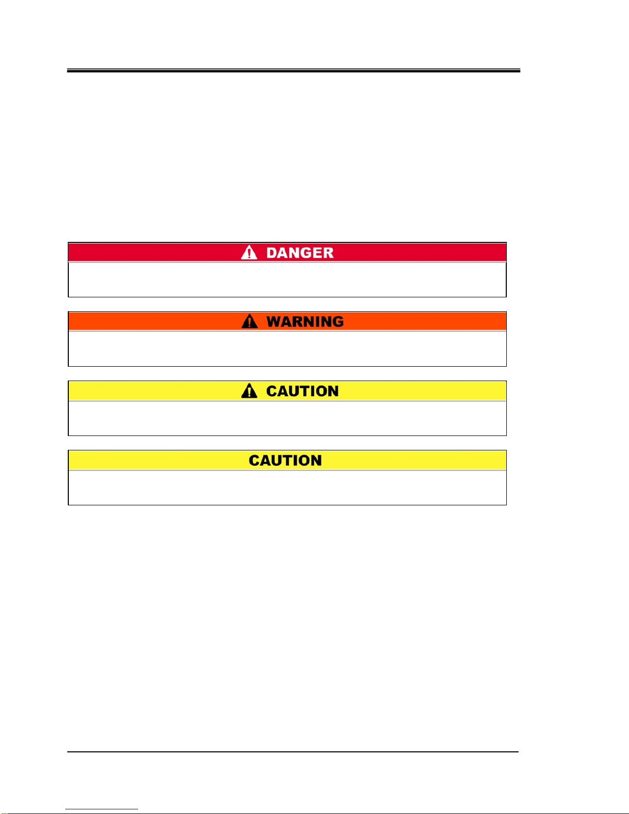
“DANGER”, “WARNING” and “CAUTION” signs are in order according to
severity (DANGER> WARNING> CAUTION).
1.3.2 Definition of “Serious injury” and “Minor injury”
“Serious injury”
This term describes injuries that result in after effects including loss of
eyesight, burns, electrical shock, fracture, poisoning, etc. and requires
long-term treatment or hospitalization.
“Minor injury”
This term describes injuries that do not need long-term treatment or
hospitalization. (Others excluded from serious injury.)
“WARNING”: Hazard that MAY cause serious personal injury or death during
operation.
“DANGER”: Hazard that WILL cause serious personal injury or death during
operation.
“CAUTION”: Hazard that MAY cause minor personal injury.
“CAUTION without exclamation symbol”: Hazard that MAY cause damage or failure
of the product, facility, devices, ect.
Page 11
HRX-OM-Q026-B
Chapter 1 Safety Instructions
HRSH Series 1.4 Product Label
1-3
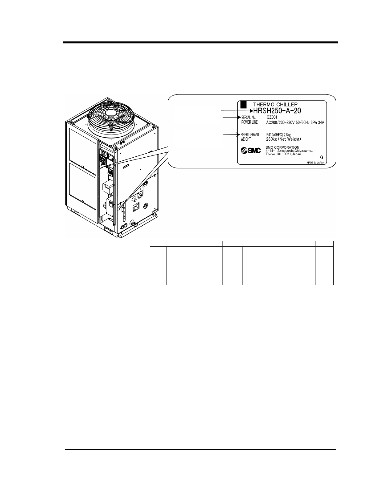
1.4 Product Label
Information about the product, such as Serial No. and Model No. can be
found on the model label. This information is needed when contacting an
SMC sales distributor.
How to see the serial number Q Z 001 (December 2012)
O O 001
Year Symbol Remarks Month Symbol Remarks
Serial
no.
2012 Q
1 O
2013 R 2 P
2014 S 3 Q
↓ ↓
Repeated
from
A to Z in
alphabetical
order
↓ ↓
Repeated from
O to Z in alphabetical
order, with O for
January and Z for
December
-
Fig. 1-1 Position of product label
∗
An example of HRSH250-A-20
Model number
Serial number
z Kind and
amount
Page 12
HRX-OM-Q026-B
Chapter 1 Safety Instructions
1.5 Safety Measures HRSH Series
1-4
1.5 Safety Measures
1.5.1 Safety Instructions for Use
z Read and understand this manual carefully before using the product.
z Before starting maintenance of the product, be sure to lock out and tag out the
breaker of the user's power supply.
z If operating the product during maintenance, be sure to inform all workers nearby.
z Use only the correct tools and procedure when installing or maintaning the product.
z Use personal protective equipment where specified (“1.5.2Personal Protective
Equipment”)
z Check all parts and screws are fitted correctly and securely after maintenance.
z Avoid working in a drunken or sick condition, which might cause an accident.
z Do not remove the panels except for the cases permitted in this manual.
z Do not remove the panels during operation.
1.5.2 Personal Protective Equipment
This manual specifies personal protective equipment for each work.
Transport, Installing and Uninstalling
Handling of circulating fluid
Operation
Always use safety shoes, gloves and head protection when
transporting, installing or uninstalling the product.
Always use safety shoes, gloves, mask, apron and eye protection
when handling the circulating fluid.
Always use safety shoes and gloves when operating the product.
Follow the instructions below when using the product. Failure to
follow the instructions may cause an accident and injury.
Page 13
HRX-OM-Q026-B
Chapter 1 Safety Instructions
HRSH Series 1.6 Emergency Measures
1-5
1.6 Emergency Measures
When emergency conditions such as natural disaster, fire and earthquake,
or injury occurs, shut off the breaker of the user’s power supply that supplies
the power to the product.
1.7 Waste disposal
1.7.1 Disposal of refrigerant and compressor oil
The product uses hydro fluorocarbon type refrigerant (HFC) and
compressor oil. Comply with the laws and regulations in each country for the
disposal of refrigerant and compressor oil. The type and quantity of
refrigerant is described on the 1.4 Product Label
If these fluids need to be recovered, read and understand the instructions
below carefully. If there is any unclear point, contact an SMC's sales
distributor.
1.7.2 Disposal of product
The disposal of the product must be handled by a specialized industrial
waste disposal agency in accordance with local laws and regulations.
z Only maintenance personnel or qualified people are allowed to
open the cover panels of the product.
z Do not mix the compressor oil with domestic waste for disposal.
Also, the disposal of the waste must only be conducted by specific
facilities that are permitted for that purpose.
Even when the power supply swich is turned off, some of the internal
circuits are still energized, unless the user’s power supply is shut off.
Be sure to shut off the breaker of the user’s power supply.
z Comply with the laws and regulations in each country for the
disposal of refrigerant and compressor oil.
z The release of refrigerant in to the atmosphere is banned by law.
Recover it with specific equipment and dispose of it correctly.
z Only people who have sufficient knowledge and experience about
the product and its accessories are allowed to recover the
refrigerant and compressor oil.
Page 14

HRX-OM-Q026-B
Chapter 1 Safety Instructions
1.8 Material Safety Data Sheet (MSDS) HRSH Series
1-6
1.8 Material Safety Data Sheet (MSDS)
If the material safety data sheets of chemicals used in this product are
needed, contact an SMC's sales distributor.
Any chemicals used by the user must be accompanied by an MSDS.
Page 15
HRX-OM-Q026-B
Chapter 2 Name and Function of Parts
HRSH Series 2.1 Model number of product
2-1
Chapter 2 Name and Function of Parts
2.1 Model number of product
The product can be ordered with the model number configured as shown
below.
The product needs to be handled in different ways depending on the part
number. Refer to “1.4 Product Label and check the part number of the
product.
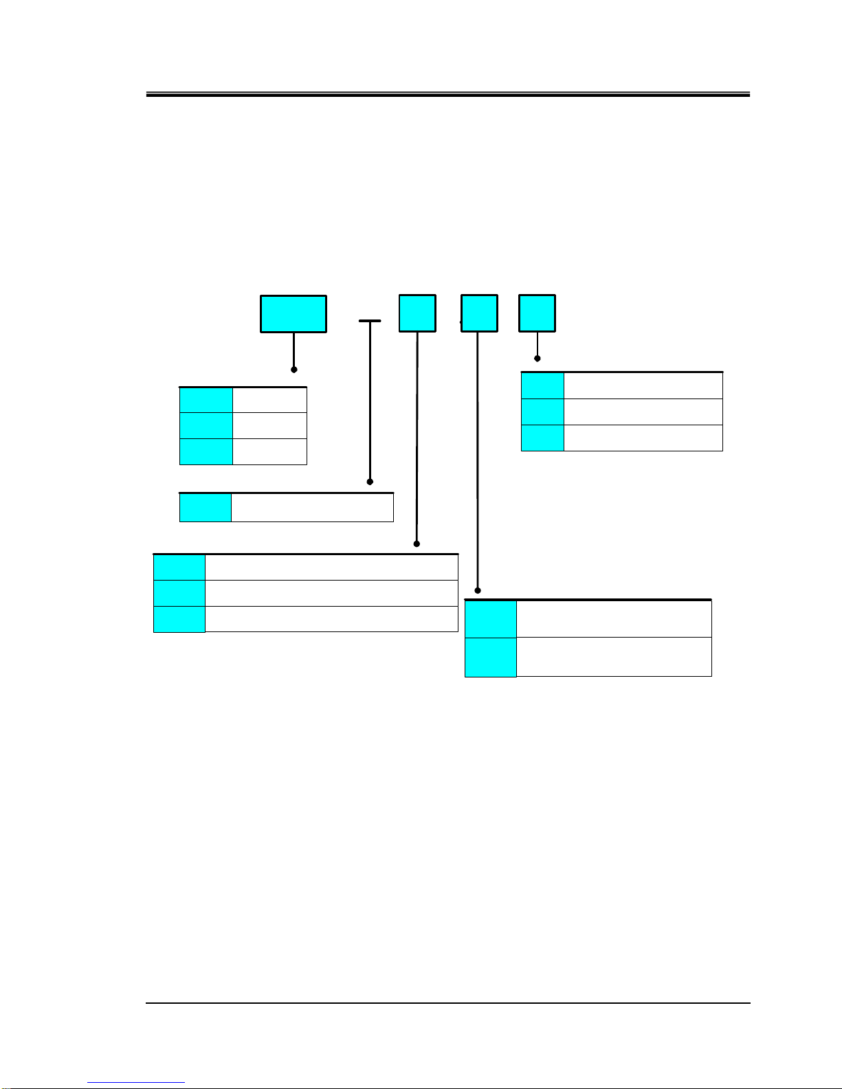
HRSH
①Cooling capacity
②Cooling method
③Piping thread type
④Power supply
- - -
⑤Option
A Air-cooled refrigeration
None
Nill
Earth leakage breaker
Fluid fill port
B
※1
K
※2
※2:Manual fluid fill port that is different from
the automatic fluid-fill function.
This enables that circulating fluid can be
filled manually without removing the side panel.
(In case of without K option, circulating
fluid can be filled manually removing
the side panel.)
Nil
Rc
F G (Rc-G thread adapter set is included)
N NPT (Rc-NPT thread adapter set is included)
A
20
150 15kW
250
200 20kW
25kW
20
AC200V/200-230V(50/60Hz)
3phase
40
※3
AC380-415 50/60Hz 3phase
※1:In case of power supply '40', this is
standard. (with a handle)
※3:Power supply '40' is available only for HRSH250
Fig. 2-1 Model number of product
Page 16
HRX-OM-Q026-B
Chapter 2 Name and Function of Parts
2.2 Name and Function of Parts HRSH Series
2-2
2.2 Name and Function of Parts
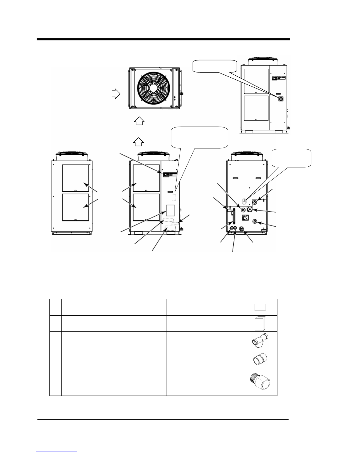
Fig. 2-2 Names of each part
Table 2-1 Accessory list
①
Alarm cord list label
2pc.
(English 1pc. /Japanese 1pc.)
②
Operation manual
2pc.
(English 1pc./Japanese 1pc.)
③
Y strainer (40meshes) 25A 1pc.
④
Barrel nipple 25A 1pc.
For HRSH∗∗∗-AF-∗∗
G thread adapter set (HRS-EP014)
1set
⑤
For HRSH∗∗∗-AN-∗∗
NPT thread adapter set (HRS-EP013)
1set
Circulating fluid
outlet port Rc1
Circulating fluid
return port Rc1
Automatic fluid
fill port Rc1/2
Overflow port
Rc1
Signal cable entry
(Grommet with membrane)
Tank drain port
Rc3/4 (closed by a
ball valve)
Power cable entry
(Grommet with membrane)
Product
Fluid level
gauge
Option K
[Fluid fill port]
Option B
[Earth leakage breaker]
Inside the panel
Dust-proof
Power terminal
(Inside the panel)
Signal connectors
(
Inside the panel)
Operation
display panel
Ventilation
Ventilation air inlet
Ventilation air inlet
Accessories
(③, ④, (⑤))
Accessories
(①, ②)
In case of HRSH∗∗∗-A∗-40-∗
Breaker handle
Page 17
HRX-OM-Q026-B
Chapter 2 Name and Function of Parts
HRSH Series 2.3 Function of Parts
2-3
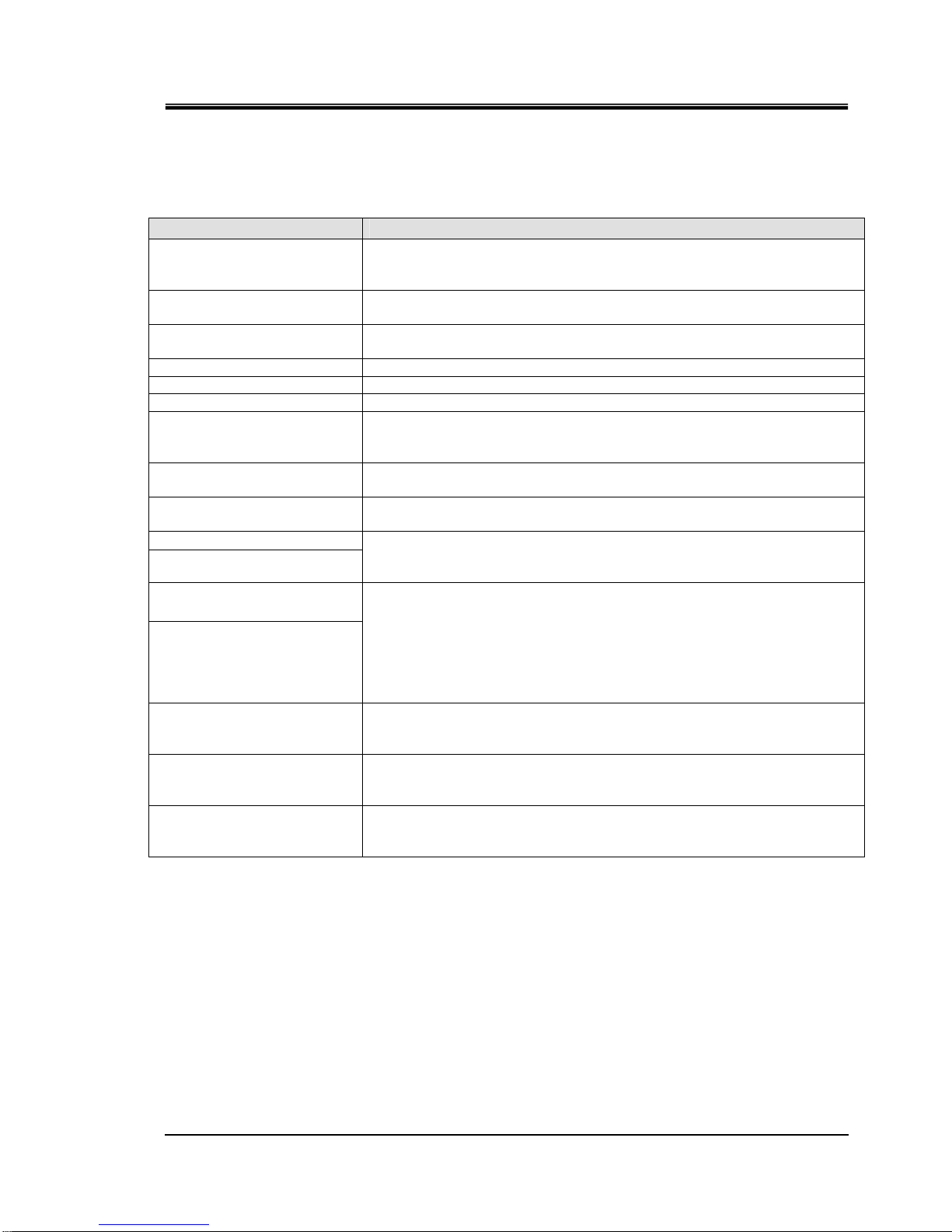
2.3 Function of Parts
The function of parts is as follows.
Table 2-2 Function of parts
Name Function
Operation display panel
Runs and stops the product and performs settings such as the circulating
fluid temperature.
For details, refer to ’’2.4 Operation display panel’’.
Fluid level gauge
Indicates the circulating fluid level of the tank. Confirm the level is between
HIGH and LOW. For details, refer to “3.5Fill of circulating fluid”.
Model label
Shows the product information such as model number and serial number.
For details, refer to ‘’1.4 Product Label’’.
Circulating fluid outlet port The circulating fluid flows out from the outlet port.
Circulating fluid return port The circulating fluid returns to the return port.
Tank drain port This drain port to drain the circulating fluid out of the tank.
Automatic fluid fill port
Piping to the automatic fluid filling port enables easy supply of the circulating
fluid through the ball tap in the reservoir.The supply pressure should be
within the range of 0.2 to 0.5MPa.
Overflow port
Be sure to connect piping from this port to sump pit to discharge the exsess
circulating fluid that caused by fluid level rising.
Dust-proof filter
Inserted to prevent that the dust and contamination are clung on the
air-cooled condensers directly. For details, prefer to “7.2.2Monthly check”.
Power cable entry
Power terminal
Insert the power cable to the power cable entry and connect it to the power
terminal. For details, refer to “3.3.2Electrical wiring” and “3.3.3Preparation
and wiring of power supply cable”.
Signal cable entry
Signal connecors
Insert the signal cable to the signal cable entry and connect it to the signal
connectors. For details, refer to “3.3.4Contact input/output communicatin
wiring”, “3.3.6Wiring of Run/stop signal input・Remote signal input”,
“3.3.8Wiring of external switch signal input”, “3.3.9Wiring of operation signal
output and alarm signal output” , “3.3.8RS-485 Communication wiring” ,
“3.3.9RS-232C Communication wiring or the Operation manual
Communication function.
Earth leakage breaker
(When option B [Earth leakage
breaker]I is selected.
Shuts off the power supply to the internal eqipment of product.
(Parts energized remained in the product)
Refer to “3.3.2Electrical wiring” for the earth leakage breaker.
Breaker handle
(In case of HRSH∗∗∗-A∗-40-∗)
Shuts off the power supply to the internal eqipment of product.
(Parts energized remained in the product)
Refer to “3.3.2Electrical wiring” for the earth leakage breaker.
Fluid fill port
(When option K [Fluid fill port]
is selected.)
Customer who will not use the automatic fluid-fill function can fill the
circulating fluid without removing the panel.
Page 18
HRX-OM-Q026-B
Chapter 2 Name and Function of Parts
2.4 Operation display panel HRSH Series
2-4
2.4 Operation display panel
The operation panel on the front of the product controls the basic operation
of the product.
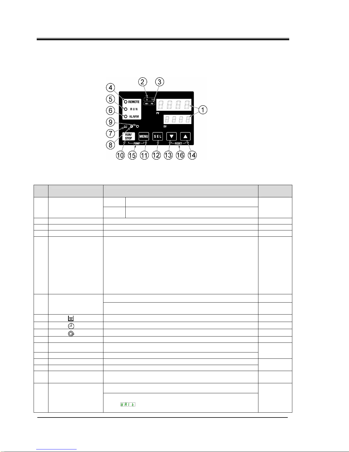
Fig. 2-3 Operation display panel
Table 2-3 Operation display panel
No Description Function
Reference
page
PV
Displays the temperature and pressure of the circulating
fluid and alarm codes.
①
Digital display
(7 segment,
4 digits)
SV
Displays the set temperature of the circulating fluid and
the set values of other menus.
5.2
② [ oC oF ] lamp Displays the unit of display temperature (oC or oF). 5.12
③ [MPa PSI] lamp Displays the unit of display pressure (MPa or PSI). 5.13
④ [REMOTE] lamp Lights up during remote operation by communication. 5.21
⑤ [RUN] lamp
・Lights up when the product is started and in operation. Goes off
when the product is stopped.
・Blinks during stand-by for stop (Interval 0.5 seconds).
・Blinks during independent operation of the pump (Interval 0.3
seconds).
・ Blinks during anti-freezing function (At standby: Interval 2
seconds, At operation: Interval 0.3 seconds).
・Blinks during warming up function (At standby: lit on for 0.5
seconds and off for 3 seconds, At operation: interval 0.3
seconds.)
4.4
Flashes with buzzer when alarm occurs (Interval 0.3 seconds). 5.3
⑥ [ALARM] lamp
Blinks while AL25 is OFF (lit on for 0.5 seconds and off 3
seconds.)
5.20
⑦
[ ] lamp Lights up when the fluid level lowers. 4.3
⑧
[ ] lamp Lights up while the run timer or stop timer function is working. 5.6
⑨
[ ] lamp
Lights up when the product is in automatic operation.
5.9
⑩ [RUN/STOP] key
Makes the product start or stop.
4.4
⑪ [MENU] key
Shifts the main menu (display screen of temperature) the other
menu (entry of set values and monitor screen).
⑫ [SEL] key
Changes the item in menu and enters the set value.
5.1
⑬ [▼] key
Decreases the set value.
⑭ [▲] key
Increases the set value.
-
⑮ [PUMP] key
When the [MENU] and [RUN/STOP] keys are held down
simultaneously, the pump starts running independently.
4.3
Press the [▼] and [▲] keys simultaneously. This will stop the alarm
buzzer and reset the [ALARM] lamp.
⑯ [RESET] key
Keep the [▼] and [▲] keys pressed down simultaneously for 3
seconds to reset AL46 and AL48.(After resetting AL48,
WAIT(
) will be displayed and the product cannot run for 40
seconds. Restart 40 seconds later after resetting.
6.3
Page 19
HRX-OM-Q026-B
Chapter 3 Transport and Setting Up
HRSH Series 3.1 Transport
3-1
Chapter 3 Transport and Setting Up
3.1 Transport
The product is heavy and has potential danger at transport. Also, to prevent
damage and breakage of the product, be sure to follow these instructions for
transport.
z Drain the residual fluid from the piping as much as possible to
prevent any spillage.
z Only persons who have sufficient knowledge and experience
about the product and system are allowed to transport and set up
the product.
z Especially pay attention to personal safety.
Never lay the product on its side.
The compressor oil will leak in to the refrigerant piping, which may
cause early failure of the compressor.
z When moving by folklift, take care not to hit the folk to the cover
panels and piping ports of the product.
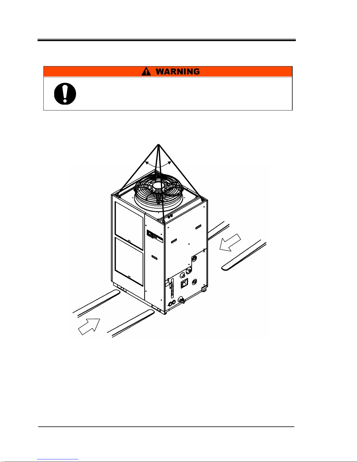
z Be sure to use all the four eye bolts when sling the product.
z The slant angle of each rope should be less than 60 degrees.
z When moving the product by a folklift, insert the fork into the right
psitions refering to 3.1.1
Moving by forklift and slinging.
Page 20
HRX-OM-Q026-B
Chapter 3 Transport and Setting Up
3.1 Transport HRSH Series
3-2
3.1.1 Moving by forklift and slinging
Fig 3-1 Fork insert and slinging position
The wights of the product are HRSH150/200:Approx. 215kg,
HRSH250:Approx. 280kg.
Moving by forklift and slinging should be done by persons who have
the licenses.
Position to sling
Less than 60°
Fork insert position
Fork Insert position
Page 21
HRX-OM-Q026-B
Chapter 3 Transport and Setting Up
HRSH Series 3.1 Transport
3-3
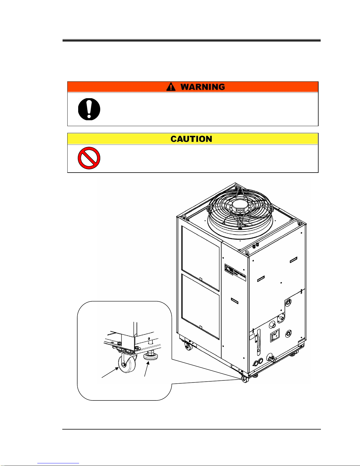
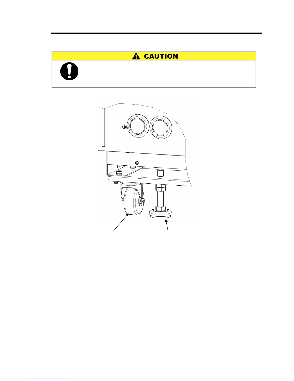
3.1.2 Moving by casters
<In case of purchasing the optional accessories, “Caster Adjuster-foot kit”
(HRS-KS001
/KS002) separately and after fastening it to the product.>
Fig. 3-2 Transportation using casters
Do not hold the piping connections and grips of the panels when
moving by casters. It may cause a damage to the product.
Push the corners of the product.
The wights of the product are HRSH150/200:Approx. 215kg, HRSH250:
Approx. 280kg.
Moving the product by casters should be done by 2 persons or more.
Raise the adjuster
foot.
Swivel
caste
r
Each swivel caster can
rotate 360 degrees freely.
Page 22
HRX-OM-Q026-B
Chapter 3 Transport and Setting Up
3.2 Installation HRSH Series
3-4
3.2 Installation
3.2.1 Environment
The product must not be operated, installed, stored or transported in the
following conditions. Potential malfunction or damage to the product may
occur if these instructions are disregarded.
The product does not conform to any clean room specifications. The pump
and ventilating fan inside the product generate particles.
z Location that is exposed to steam, salt water or oil.
z Location that is exposed to dust or powder material.
z Location that is exposed to corrosive gas, organic solvent, chemical
solution, or flammable gas (the product is not explosion-proof)
z Location where the ambient temperature is out of the following range:
In transportation and In storage -15 to 50°C
(Should not be water or circulating fluid circuit in the product)
In operation -5 to 45°C(Use 15% ethylene glycol
aqueous solution if operating in a place where the circulating fluid temp. or
ambient temperature is lower than 10
°C.)
z Location where condensation forms on the inside electrical parts.
z Location that is near heat sources and poor in ventilation.
z Location that is subjected to abrupt changes in temperature.
z Location that is subjected to strong electromagnetic noise (intense electric
field, intense magnetic field, or surges).
z Location that is subjected to static electricity, or conditions where static
electricity can discharge to the product.
z Location that is subjected to strong high frequencies raditation
(microwaves).
z Location that is subjected to potential lightning srtike.
z Do not set up the product in places possibly exposed to leakage of
flammable gas. Should any flammable gas stay around the
product, the product may cause a fire.
z Keep the product horizontal to a rigid and flat floor which can
resist the weight of the product, and take measures to prevent the
product from tipping over. Improper installation may cause water
leakage, tipping, damage of the product or injure the operator.
z Keep the ambient temperature of the product between -5 to 45
o
C.
Operation out of this ambient temperature range may cause a
malfunction of the product.
z The installer/end user is responsible for carrying
out a acoustic noise risk assessment on the equipment after
installation and taking appropriate measures as required.
Page 23

HRX-OM-Q026-B
Chapter 3 Transport and Setting Up
HRSH Series 3.2 Installation
3-5
z Location at altitudes of 1000m or higher (except during product storage
and transport). In case of using at altitudes of 1000m or higher, please
contact us.
z Location where the product is affected by strong vibrations or impacts.
z Condition that applies external force or weight causing the product to be
damaged.
z Location without adequate space for maintenance as required.
z Location that is exposed to splash of the water that is higher than IPX4.
Page 24
HRX-OM-Q026-B
Chapter 3 Transport and Setting Up
3.2 Installation HRSH Series
3-6
3.2.2 Location
Installation of multiple products
Keep sufficient space between products so that the air vented from one product will not be taken
in by other products.
Installation at indoor site
① In case of facility having a large installation area (that can vent the air naturally)
Make an air outlet on a wall at a high level and air inlet on a wall at a low level, to allow for
adequate airflow.
② In case of facility having a small installation area (that can not vent the air naturally)
Make a forced air exhaust vent on a wall at a high level and an air inlet on a wall at a low level.
③ Using duct to exhaust the air
In case the indoor site cannot accept the exhausted air from the product or/and is air
conditioned, ventilate by installing a duct on the outlet ventilation of the product. Do not fasten
the duct on the outlet ventilation of the product directly. Have the space at least the dust’s
diameter apart. Use a fan for the duct that considered the ventilation resistance of the duct.
Table 3-1 Amount of radiation and required ventilation
Required ventilation amount m3/min
Model
Heat
Radiated kW
Differential temp. of
3 oC between inside
and outside of
installation area
Differential temp. of
6 oC between inside
and outside of
installation area
HRSH150-A∗-20-∗
Approx.29
490 245
HRSH200-A∗-20-∗
Approx.35
590 295
HRSH250-A∗-20/40-∗
Approx.44
730 365
Installation at indoor site
The product’s splash-proof specification is IPX4.
Installation environment specification
Maximum noise: HRSH150/200…62dB(A)
HRSH250…66dB(A)
The product radiates heat from the air vent of the cooling fan.
If the product is operated with insufficient air ventilation the internal
temperature can exceed 45
oC∗
, which can cause an affect the
performance and life of the product. To prevent this ensure that
suitable ventilation is available (see below).
z Do not install in a location which can be subjected to any of the
conditions in 3.2.1 Environment.
Page 25
HRX-OM-Q026-B
Chapter 3 Transport and Setting Up
HRSH Series 3.2 Installation
3-7
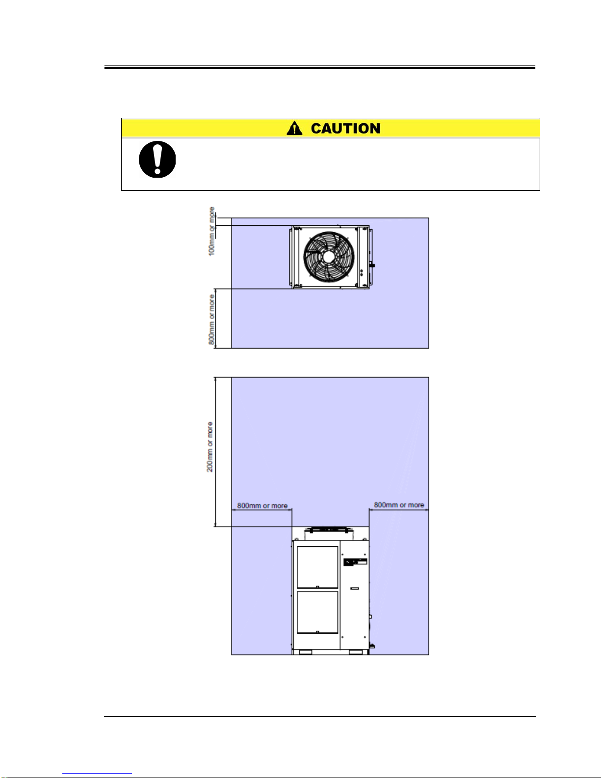
3.2.3 Installation and Maintenance Space
It is recommended to keep the space around the product shown in Fig. 3-3.
Fig. 3-3 Installation space
Have an enough space for the ventilation for the product. Otherwise it
may cause a lack of cooling capacity or/and stoppage of the product.
Have an enough space for maintenance.
Top
Front
Page 26
HRX-OM-Q026-B
Chapter 3 Transport and Setting Up
3.3 Installation HRSH Series
3-8
3.3 Installation
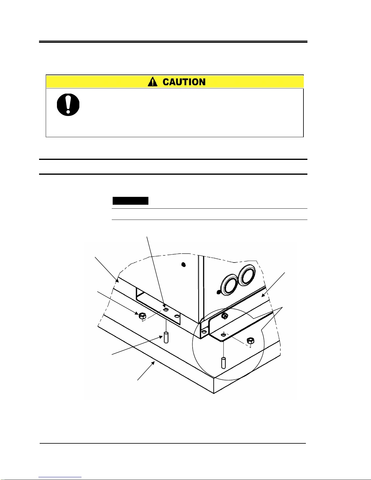
3.3.1 Installation
How to mount the product
1. Insert the product to the anchor bolts that were previously driven on the horizontal floor.
2. Fasten the nuts to the anchor bolts.
3. Make sure that there is no looseness on all the anchor bolts and nuts.
【One point】
SMC Foundations bolt set [IDF-AB500] (SUS M10x50mm) is applicable.
Fig. 3-4 Installation procedures
Install the product on the horizontal floor.
Prepare the M10 anchor bolts that are appropriate to the material of
the floor that the product will be installed. Drive the anchor bolts at
least at two places of the left and right side of the product each (totally
four places). Refer to the “8.2 Outline dimensions” for the dimensions
for the position of the anchor bolts.
Floor
Anchor bolt
Nut
Base of the product
Hole for anchor bolt (12mm)
Anchor bracket
Hole for anchor
bolt (12mm)
Page 27
HRX-OM-Q026-B
Chapter 3 Transport and Setting Up
HRSH Series 3.3 Installation
3-9
〈In case of purchasing [Caster Adjuster-foot kit] (HRS-KS001/KS002)〉
Fig. 3-5 Installation by adjuster foot
In case of using [Caster Adjuster-foot kit], be sure to use the adjuster
foot to install on the floor. The adjuster foot is not earthquake-proof.
Make an earthquake-resistant measure by the customer side.
Adjust the adjuster foot so that the gap
between the caster wheel and the floor
becomes 3mm to 5mm.
Caster
Page 28
HRX-OM-Q026-B
Chapter 3 Transport and Setting Up
3.3 Installation HRSH Series
3-10
3.3.2 Electrical wiring
z Do not modify the intenal electrical wiring of the product. Incorrect
wiring may cause electrical shock or fire. Also, modifing the
internal wiring will void the product’s warranty.
z Do not connect the ground to water line, gas pipe or lightening
z Only qualified persons are allowed to wire the product.
z Be sure to shut off the user’s power supply. Wiring with the
product energized is strictly prohibitted.
z The wiring must be conducted using cables complying with “Table
3-2” firmly and secured to the product to prevent the external force
of cables being applied to the terminals. Incomplete wiring or
improper securing of wiring may cause electrical shock, excessive
heat and fire.
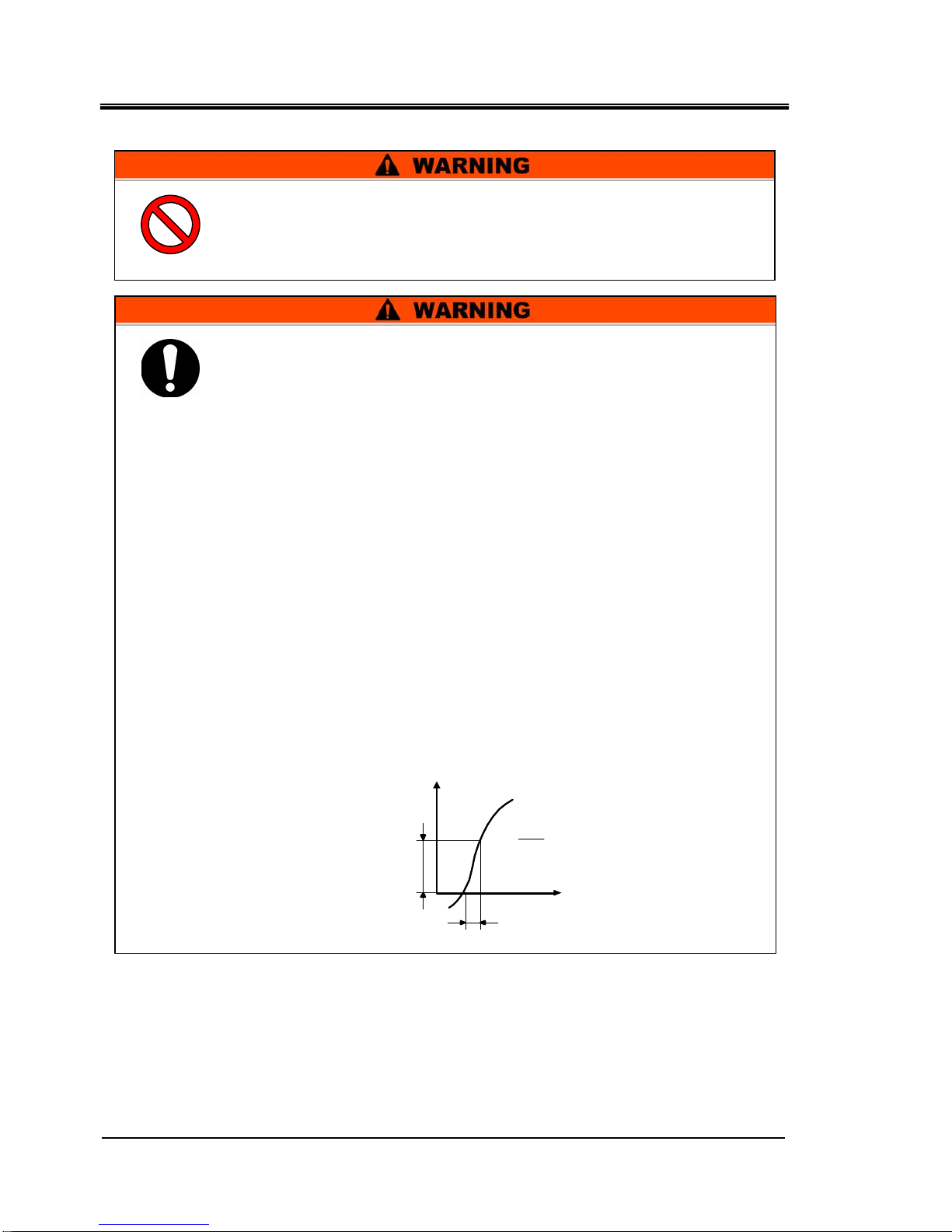
z Ensure a stable power supply with no voltage surges.
z Ensure that an Earth Leakage Breaker is used in the power supply
of the product. See “Table 3-2”.
z Use a power supply suitable for the specifications of the product.
Be sure to connect the ground connection.
z Ensure that a lock out facility is availble on the power supply.
z Each product must have its own separate Earth Leakage Breaker.
Otherwise there can be a risk of electric shock or fire.
z Ensure that no harmonics are superimposed at power supply.
(Do not use inverter etc.)
z Supply a steady power supply which is not affected by surges or
distortion. In particular, if the voltage rate of increase (dv/dt) at
zero crossing exceeds 40V/200μsec, it may cause malfunction.
V
dV
dt
dt
= V
oon
dV
t
Voltage rise %
Time
Voltag
e
Page 29
HRX-OM-Q026-B
Chapter 3 Transport and Setting Up
HRSH Series 3.3 Installation
3-11
Power supply cable and Earth Leakage Breaker
Prepare the power supply shown in the following table. For the connection
between the product and power supply, use the power supply cable and
earth leakage breaker shown below.
Table 3-2 Power supply cable and Earth Leakage Breaker(Recommended)
Earth leakage breaker
*1
Model
Power
supply
voltage
Terminal
block
screw
diameter
Recomm
ended
crimp
terminal
Cable qty. x
size
Rated
current
[A]
Sensitivity
of leak
current
[mA]
HRSH150-A∗-20-∗
30
HRSH200-A∗-20-∗
40
HRSH250-A∗-20-∗
AC200/
200-230V
50/60Hz
3phase
M5 R8-5
4 cores x
AWG8
(4 cores x
8mm2)
(including
ground)
50
30
R5.5-5
3x5.5mm2
(3xAWG10)
HRSH250-A∗-40-∗
AC380-415V
50/60Hz
3phase
M5
R14-5
For
ground
line
1x14mm2
(1xAWG6)
For
ground line
30 30
*1: A specified earth leakage breaker is installed for option B [Earth leakage breaker] of each model.
If the product is not option B [Earth leakage breaker], please prepare an earth leakage breaker by
the customer side.
A specified earth leakage breaker is installed for HRSH250-A∗-40-∗ .
3.3.3 Preparation and wiring of power supply cable
z The electrical facilities should be installed and wired in
accordance with local laws and regulations of each country and by
a person who has knowledge and experience.
z Check the power supply. Operation with voltages, capacities and
frequencies other than the specified values can cause fire and
electrical shock.
z Wire with an applicable cable size and terminal. Forcibly mounting
with an unsuitable size cable ma
y
result in heat generation or fire.
Page 30
HRX-OM-Q026-B
Chapter 3 Transport and Setting Up
3.3 Installation HRSH Series
3-12
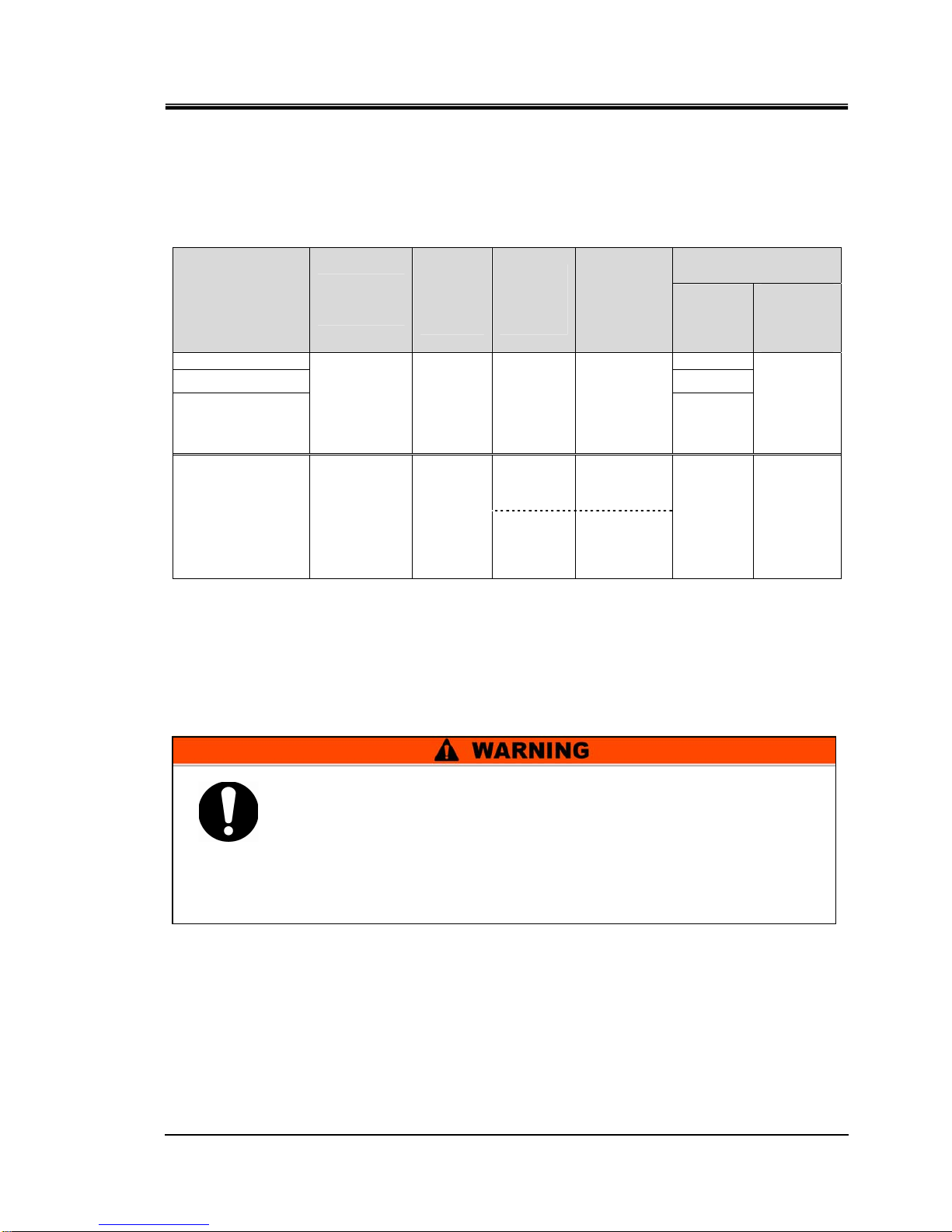
In case of option B [Earth leakage breaker] and HRSH∗∗∗-A∗-40-∗
Breaker’s operating characteristic
Be sure to lock out and tag out the breaker of the facility power supply
(customer power supply facility) before wiring.
Be sure to connect the power supply cable from the product side first,
and then connect the breaker of the facility power supply (the user’s
machine power supply).
When the panel is removed or mouted, be sure to wear protective
shoes and gloves to prevent injury with the edge of the panel.
A breaker that has the operating characteristic below is installed. Please use a
breaker that has the same or longer operating time as/than this for the customer
side (primary side). If it is a shorter operating time, there is a possibility of
accidental breaker trip due to the internal motors’ inrush currents of this product.
4h
2h
1h
30min
20min
14min
10min
6min
4min
2min
1min
30s
20s
10s
5s
2s
1s
0.5s
0.2s
0.1s
0.05s
0.02s
0.01s
100 135 200 300 400 500 600700 1000 1500 2000 3000 4000
Current (% for breaker capacity)
Operating time
Min.
Max.
Page 31

HRX-OM-Q026-B
Chapter 3 Transport and Setting Up
HRSH Series 3.3 Installation
3-13
Preparation for operation
1. Remove four screws to remove the front panel for the electrical unit.
Fig. 3-6 Remove the front panel for the electrical unit
2. Hold the handle and put up the front panel of the electrical unit, and remove it.
Fig. 3-7 Remove the front panel of the electrical unit
Handle
A
Screw
Front panel for the
electrical unit
In case of HRSH∗∗∗-A∗-40-∗
OFF
Note: Please turn off the
breaker handle. The
front panel of the
electrical unit cannot
be removed without
turning off the breaker.
Page 32

HRX-OM-Q026-B
Chapter 3 Transport and Setting Up
3.3 Installation HRSH Series
3-14
3. Connect the power supply and the ground cable as shown in the figure below.
Fig. 3-8 Wiring of power supply cable
∗ Connect over current protection to the power cable connected to the equipment in order to avoid hazard.
Inlet of the power supply
cable
Note: Prepare a cable tie.
Fasten the power cable to the
mount on the base by the
cable tie.
View A
L1 L2 L3 PE
Mount for cable tie
Page 33

HRX-OM-Q026-B
Chapter 3 Transport and Setting Up
HRSH Series 3.3 Installation
3-15
3.3.4 Contact input/output communicatin wiring
The product has contact input/output communication that has the functions
that described below. Wire referring to each function’s chapter. (For the
details of the functions, refer to the operation manual communication
function.)
z Run/stop input・Remote signal input (Refer to 3.3.5 Wiring of
Run/stop input・Remote signal input.)
z External switch signal input (Refer to 3.3.6 Wiring of external
switch signal input.)
z Output of contact output signal (Refer to 3.3.7 Wiring of contact
output signal.)
Use the signal cable described below for wiring of each function.
Signal cable
Use the cable and terminals as follows below for wiring of each function.
Table 3-3 Signal cable
Terminal specification
Terminal block
screw diameter
Crimp terminal
Cable specification
M3
1.25Y-3
0.75 mm
2
(AWG18)
Shielded cable
3.3.5 Wiring of Run/stop signal input・Remote signal input
Run/stop signal input・Remote signal input enable the product to be run and
stopped or switched DIO REMOTE and DIO LOCAL remotely by applying a
contact signal input. This chapter explains examples of wiring.
Select DIO mode as the communication mode to activate the Run/stop
signal input・remote signal input after wiring referring to the operation
manual communications function.
【Tips】
This product has two input signals. These can be customized depending on
the customer’s application.
The capacity of the output contact of the product is limited. If the capacity is not
large enough, install a relay, etc. (to allow for larger capacity). At the same time,
ensure the input current of the relay is small enough in relation to the contact
ca
p
acity of the product.
Be sure to lock out and tag out the breaker of the facility power supply
(customer power supply facility) before wiring.
Page 34

HRX-OM-Q026-B
Chapter 3 Transport and Setting Up
3.3 Installation HRSH Series
3-16
Table 3-4 Power supply, contact specifications
Name Terminal NO. Specification
5, 6, 7 (DC 24V)
Power supply output
13,14, 15 (24V COM)
DC 24V ±10% 500mA MAX
∗
1
3 (Contact input signal 1)
Contact input signal 1
11 (Common of contact output signal 1)
-Run/stop signal
input
-External switch
signal input
∗
2
4 (Contact input signal 2)
Contact input signal 2
12 (Common of contact output signal 2)
-Run/stop signal
input
-Remote signal
input
-External switch
signal input
∗
2
Switch the
input on the
operation
display panel.
Refer to the
operation
manual
communication
function.
*1: To use the power of the device, the total load current must be 500mA or less.
If the load is 500mA or more, the internal fuse will be cut to protect the product and the alarm [AL21 DC
line fuse cut] will be generated. Refer to Chapter 6 for handling of alarms.
*2: Refer to 3.3.6 Wiring of external switch signal input.
1. Prepare the switch (source voltage: 24V, contact capacity: 35mA or more, min. load
current: 5mA), and cable (3-3 Signal cable).
Page 35

HRX-OM-Q026-B
Chapter 3 Transport and Setting Up
HRSH Series 3.3 Installation
3-17
2. Connect the signal cable and switch to the terminal as follows. (This wiring is an
example.)
Fig. 3-9 Wiring of Run/stop signal input・Remote signal input (Example)
Inlet of the signal
cable
Note: Prepare a cable tie.
Fasten the signal cable to the
mount on the base by the cable
tie.
Terminal No. 5
Terminal No.13
Terminal No.11
Switch
Mount for cable tie
Terminal No. 3
Page 36

HRX-OM-Q026-B
Chapter 3 Transport and Setting Up
3.3 Installation HRSH Series
3-18
3.3.6 Wiring of external switch signal input
This product can be monitored by sampling the signal of the external switch
prepared by the customer.
Table 3-5 Power supply, contact specifications
Name Terminal NO. Specification
5, 6, 7 (DC 24V)
Power supply output
13,14, 15 (24V COM)
DC 24V ±10% 500mA MAX
∗
1
3 (Contact input signal 1)
Contact input signal 1
11 (Common of contact output signal 1)
4 (Contact input signal 2)
Contact input signal 2
12 (Common of contact output signal 2)
NPN open collector output
PNP open collector output
(Refer to the operation manual
communication function.)
*1:To use the power of the device, the total load current must be 500mA or less.
If the load is 500mA or more, the internal fuse will be cut to protect the product and the alarm [AL21 DC
line fuse cut] will be generated. Refer to Chapter 6 for handling of alarms.
One external switch can be connected to contact input signal 1 and one to
contact input signal 2. (Two in total) The external switch cannot be
connected to the contact input signal 1 depending on the communication
mode.
Table3-7 External switches used in examples .
Table 3-6 Sets external switch
Communication mode ∗1
Contact input signal 1 Contact input signal 2
Local mode
○ ○
MODBUS
○ ○
Simple
communication
protocol 1
○ ○
SERIAL mode
Simple
communication
protocol 2
× ○
DIO mode
× ○
*1:Refer to the Communications Operation Manual for more details of each mode.
Local mode: Mode allowing the product to be operated by the operation panel. (Default setting)
SERIAL mode: Mode allowing the product to be operated by serial communication.
DIO mode: Mode allowing the product to be operated by the contact input/output communication.
Example of connection
As an example of connection of an external switch, the connecting method is
shown below using the SMC flow switch (NPN, PNP).
This chapter illustrates examples of wiring
Table3-7 External switches used in examples
Name Manufacturer Part NO. Out put type
Current
consumption
PF3W721□-□□-A□(-M) NPN open collector output 50mA or less
Flow switch SMC
PF3W721□-□□-B□(-M) PNP open collector output 50mA or less
Be sure to shut off the breaker of the facility power supply (the user’s
machine power supply) before wiring.
Page 37

HRX-OM-Q026-B
Chapter 3 Transport and Setting Up
HRSH Series 3.3 Installation
3-19
Flow switch
3
6
5
11
Terminal No.
14
Blue(DC COM)
Brown(DC 24V)
Black
(Output1)
11
6
13
3
14
Terminal No.
Terminal No.
Terminal No.
Terminal No.
Blue(DC COM)
Brown(DC 24V)
Black
(Output1)
Terminal No.
Terminal No.
Terminal No.
Terminal No.
Terminal No.
Flow switch
1. Prepare the flow switch described in the table purchasing separately.
2. Depending on the external switch output type, wire the switch to the terminals for
contact input signal as shown below. (This is an example of wiring. Refer to the
operation manual communication function for the detail.)
Fig. 3-10 Wiring of the external switch (NPN open collector output) (example)
Fig. 3-11 Wiring of the external switch (PNP open collector output) (example)
Flow switch
Brown (DC 24V)
Blue(DC COM)
Black(Output1)
Flow switch
Brown (DC 24V)
Blue(DC COM)
Black(Output1)
Page 38

HRX-OM-Q026-B
Chapter 3 Transport and Setting Up
3.3 Installation HRSH Series
3-20
Setting items
Table 3-8 shows the setting items of the external switch. For details, refer to
5.21 Communication function.
Table 3-8 Setting list of the external switch
Display Item
Initial value
(Default setting)
Example
∗
Reference
page
Category
Communication mode LOC LOC
Contact input signal 1 RUN SW_A
Contact input signal 1 type ALT ALT
Contact input signal 1
delay
timer (time delay) of
reading
0 0
Contact input signal 1 OFF
detection timer
0 2
Contact input signal 2 OFF OFF
Contact input signal 2 type ALT Contact input signal 2
delay
timer (time delay) of
reading
0 -
Contact input/output communication
Contact input signal 2 OFF
detection timer
0 -
5.21
Communication
setting menu
∗ Example: Connect flow switch A to contact input signal 1 in local mode.
Page 39

HRX-OM-Q026-B
Chapter 3 Transport and Setting Up
HRSH Series 3.3 Installation
3-21
3.3.7 Wiring of operation signal output and alarm signal output
The operation signal output and alarm signal output are the outputs
generated by a contact signal to shown the status of the product.
The specifications of the contact for each signal output are as follows.
Table 3-9 Signal output contact spec. at the time of shipment
Contact output
Signal explanation
(Default setting)
Operation
At run:
Contact closed
At stop:
Contact open
Contact output signal 1
(Terminal no.0,8)
Operation status signal
output
A
With power supply
shut off:
Contact open
At remote:
Contact closed
At non remote:
Contact open
Contact output signal 2
(Terminal no.1,9)
Remote status signal
output
A
With power supply
shut off:
Contact open
At generation:
Contact open
Not generated:
Contact closed
Contact output signal 3
(Terminal no.2,10)
Alarm status signal
output
B
With power supply
shut off:
Contact open
【Tips】
This product has three output signals which can be customized depending on
the customer’s application
Signals below can be output. Refer to the Communications Operation Manual
for more details.
・Ready completion (TEMP READY) signal output
・Operation stop alarm signal output
・Operation continuation alarm signal output
・Selected alarm status signal output
・Operation start timer setting status signal output
・Operation stop timer setting status signal output
・Recovery from power failure setting status signal output
・Anti-freezing setting status signal output
・Contact input signal1, 2 pass through signal output
・Warming up function setting status output
・Anti-snow coverage function setting status output
Be sure to lock out and tag out the breaker of the facility power supply
(customer power supply facility) before wiring.
Page 40

HRX-OM-Q026-B
Chapter 3 Transport and Setting Up
3.3 Installation HRSH Series
3-22
3.3.8 RS-485 Communication wiring
Serial communication RS-485, operation start/stop, setting and reading of
circulating fluid temperature, and reading of alarm condition can be done by
remote control.
Refer to the Communications Operation Manual for more details.
Wiring of interface communication cable
z Connecting to PC
RS-485 cannot be directly connected to a normal PC. Use a RS-232C/RS485 converter which is
available on the market.
Be sure to follow the wiring procedure below for connecting multiple thermo-chillers.
z
Configuration of connection
One host computer : One thermo-chiller, or one host computer : N thermo-chillers.
(Max. 31 thermo-chillers can be connected.)
1
SD+
5
SG
9
SD-
SD+
SD- SG
Terminal
resistance
Master This product
(first slave)
1
SD+
5
SG
9
SD-
This product
(second slave)
1
SD+
5
SG
9
SD-
This product
(31
st
slaves)
Terminal
resistance120Ω
Fig. 3-12 Connection of RS-485
【Tips】
Both ends of the communication connection (the end nodes) need to be
connected to the host computer.
With or without the termination resistor (120Ω) of this product can be set by
the operation display panel. Refer to “5.21 Communication function”.
Be sure to lock out and tag out the breaker of the facility power supply
(customer power supply facility) before wiring.
Page 41

HRX-OM-Q026-B
Chapter 3 Transport and Setting Up
HRSH Series 3.3 Installation
3-23
3.3.9 RS-232C Communication wiring
Serial communication RS-232C, operation start/stop, setting and reading of
circulating fluid temperature, and reading of alarm condition can be done by
remote control.
Refer to the Communications Operation Manual for more details.
Wiring of communication cable
Be sure to wire as shown in the figure below.
z
Configuration
1 master : 1 thermo-chiller
2
3
5
RD
SD
SG
2
3
5
RD
SD
SG
Master This product
Fig. 3-13 Connection of RS-232C
Be sure to lock out and tag out the breaker of the facility power supply
(customer power supply facility) before wiring.
Page 42

HRX-OM-Q026-B
Chapter 3 Transport and Setting Up
3.4 Piping HRSH Series
3-24
3.4 Piping
Piping port size
Table 3-10 Piping port size
Name Port size1
Recommended
tightening torque
Recommended piping
specification
Circulating fluid supply Rc1
36 to 38N・m
1.0MPa and more
Circulating fluid return Rc1
36 to 38N・m
1.0MPa and more
Automatic fluid-fill port Rc3/8
28 to 30N・m
1.0MPa and more
(Automatic fluid -fill pressure
0.2 to 0.5MPa)
Overflow port Rc1
36 to 38N・m
ID25mm and more
Length 5m and less
Tank drain port Rc3/4
28 to 30N・m
ID 19mm and more
【Tips】
<In case of HRSH∗∗∗-∗N-∗>
A set of thread adapters that converts the connections from Rc to NPT is
enclosed as an accessory. Be sure to use this for NPT piping.
<In case of HRSH∗∗∗-∗F-∗>
A set of thread adapters that converts the connections from Rc to G is
enclosed as an accessory. Be sure to use this for G piping.
z Connect piping firmly. Incorrect piping might cause leakage of
supplied or drained leakage and wet surrounding area and facility.
z Pay attention not to allow dust and foreign materials to enter into
water circuit etc. during connection of piping.
z Hold the piping port firmly with specific wrench when tightening.
z The piping should be selected with due consideraton of pressure
and temperature. Otherwise the piping can burst in service.
Page 43

HRX-OM-Q026-B
Chapter 3 Transport and Setting Up
HRSH Series 3.4 Piping
3-25
How to connect piping
Tighten the piping to each connection as follows below.
Fig. 3-14 Tightening of piping
How to connect to the drain port
When piping the drain port, hold the ball valve of the drain port with a wrench
not to rotate it.
Fig. 3-15 Connection to the drain
Tank drain port
Hold the ball valve.
Without holding the ball valve of the drain port with a wrench, the ball
valve may rotate and it may cause a fluid leakage and malfunction of
the product. Be sure to hold the ball valve of the drain por
t.
Note: Incase of using the Y
strainer of the accessory, fasten
it on the return port.
Clean the filer of the strainer
after the trial operation before
the proper operation
Sealant
Y strainer
25A
Barrel
nipple 25A
Sealant
Connetion port
Page 44

HRX-OM-Q026-B
Chapter 3 Transport and Setting Up
3.4 Piping HRSH Series
3-26
Recommended piping circuit
Thermo chiller
Automatic flui-fill port
Circulationg fluid outlet port
Circulating fluid return port
Overflow port
Drain port
To sump pit
Fluid supply
Customer's
system
1
2
2
2
1
2
4
3
5
Fig. 3-16 Recommended piping circuit
No. Name Size
1 Valve Rc1/2
2 Valve Rc1
3 Y strainer 25A (40meches) (Accessury) Rc1
4 Flowmeter
Prepare a flowmeter that has an appropriate flow
rate range.
5 Valve (Part of thermo chiller) Rc3/4
Page 45

HRX-OM-Q026-B
Chapter 3 Transport and Setting Up
HRSH Series 3.5 Fill of circulating fluid
3-27
3.5 Fill of circulating fluid
3.5.1 Auto fluid-fill function
Open the fluid supply valve that is connected to the automatic fluid-fill port
by the customer.
Fluid supply will be started and stopped automatically by the ball tap in the
tank.
Fig. 3-17 Fluid level gauge
z Check the drain port is closed by the valve to prevent the supplied
circulating fluid from draining out.
z When the circulating fluid temperature set and/or the ambient
temperature is lower than 10 deg. C, use 15% aqueous solution of
ethylene glycol. Otherwise it may cause icing of the fluid
z Confirm that the fluid level is between “HIGH” and “LOW” level of the
fluid level gauge.
z Be sure to connect the piping from the overflow port to the sump pit
to drain the excessive amount of the fluid from the tank.
Fluid level displayed range
Fluid level gauge
z If tap water is used, refer to 7.1Control of Circulating Fluid Quality.
z If 15% ethylene glycol aqueous solution is used, dilute pure
ethylene glycol with water. Additives such as antiseptics cannot
be used.
z If deionized water is used, the conductivity should be 1μS/cm and
higher (Electrical resistivity: 1MΩ・cm and lower).
Page 46

HRX-OM-Q026-B
Chapter 3 Transport and Setting Up
3.5 Fill of circulating fluid HRSH Series
3-28
15% aqueous solution of ethylene glycol
When a 15% aqueous solution of ethylene glycol is used, prepare the ethylene glycol aqueous
solution separately.
To control the density of the ethylene glycol aqueous solution, a densitometer is available separately
from SMC.
Item No Remarks
Ethylene glycol aqueous solution 60% HRZ-BR001
Please dilute to 15% with tap
water and use it.
Densitometer HRZ-BR002
-
Piping of the overflow
Piping name Port size Piping specification
Automatic fluid fill port Rc1/2
Supply pressure: 0.2~0.5MPa
Overflow port Rc1
Should be ID25mm and more length 5m and less and
avoid riser piping (trapping part).
Fig. 3-18 Piping of the automatic fluid-fill port and overflow
z When a 15% aqueous solution of ethylene glycol is used, check the
density periodically because the density will be lower due to the
automatic fluid-fill function.
z When using the 15% aqueous solution of ethylene glycol, collect
the overflowed fluid in the sump pit and dispose it according to the
local low of the country and area that the product is installed.
No riser piping
Obstacle
To sump pit
To sump pit
Piping of automatic
fluid-fill port
Piping of overflow
port
Piping of automatic
fluid-fill port
Piping of overflow
port
Riser piping
Page 47

HRX-OM-Q026-B
Chapter 3 Transport and Setting Up
HRSH Series 3.5 Fill of circulating fluid
3-29
3.5.2 Fill of fluid without using auto fluid-fill function
In case of filling the circulating fluid without using auto fluid-fill function, please fill the
fluid from the fluid fill port on the tank removing the right side panel upper.
1. Remove the screws (6 places) to remove the right side panel upper.
Fig. 3-19 Removing the screws
2. Hold the handle and put up the right side panel upper, and remove it.
There is a fluid fill port on the tank. Please remove the wing nuts and lid.
Fig. 3-20 Removing the right side panel upper and lid of fluid fill port
Screws
Right side panel upper
Handle
Wing nut
Lid
Fluid fill port
Note: Take care not to lose the
wing nut.
Packing
Page 48

HRX-OM-Q026-B
Chapter 3 Transport and Setting Up
3.5 Fill of circulating fluid HRSH Series
3-30
3. Fill the circulating fluid from the fluid fill port.
Please fill the circulating fluid between “HIGH” and “LOW” level of the fluid level gauge.
Fig. 3-21 Filling the fluid to the fluid fill port (An example)
z Check the drain port is closed by the valve to prevent the supplied
circulating fluid from draining out.
z Confirm that the fluid level is between “HIGH” and “LOW” level of the
fluid level gauge.
z Be sure to connect the piping from the overflow port to the sump pit
to drain the excessive amount of the fluid from the tank.
Page 49

HRX-OM-Q026-B
Chapter 3 Transport and Setting Up
HRSH Series 3.5 Fill of circulating fluid
3-31
3.5.3 For option K [Fluid fill port]
Open the cap of the fluid fill port and fill the circulating fluid up to the level between the
“HIGH” and “LOW” of the fluid level gauge.
Fig. 3-22 Filling the fluid to the fluid fill port (An example)
z Confirm that the fluid level is between “HIGH” and “LOW” level of the
fluid level gauge.
z Be sure to connect the piping from the overflow port to the sump pit
z Check the drain port is closed by the valve to prevent the supplied
circulating fluid from draining out.
Page 50

HRX-OM-Q026-B
Chapter 3 Transport and Setting Up
3.5 Fill of circulating fluid HRSH Series
3-32
Page 51

HRX-OM-Q026-B
Chapter 4 Starting the Product
HRSH Series 4.1 Before Starting
4-1
Chapter 4 Starting the Product
4.1 Before Starting
z Check the following items before starting the product.
Installation conditions
z Check the product is installed horizontally.
z Check that there are no heavy objects on the product, and the external
piping is not applying excessive force to the product.
Connection of cables
z
Check the power, ground and communications (optional) cables are
correctly connected.
Circulating fluid
z
Check proper connection of piping at inlet and outlet.
Automatic fluid filling piping
z
Confirm that the automatic fluid filling port piping is connected properly.
Over flow port piping
z
With or without using the automatic fluid filling function, piping is
necessary.
Fluid level gauge
z
Ensure that the fluid level is between ‘HIGH’ and ‘LOW’.
Only people who have sufficient knowledge and experience about the
product and its accessories are allowed to start and stop the product.
Page 52

HRX-OM-Q026-B
Chapter 4 Starting the Product
4.2 Preparation for Start HRSH Series
4-2
4.2 Preparation for Start
4.2.1 Power supply
Turn on the breaker of the customer’s power supply.
When the product is switched on, the operation panel displays the following
conditions.
z The initial screen (HELLO screen) is displayed for 8 seconds on the
operation display panel. Then, the display changes to the main screen
which displays the circulating fluid outlet temperature.
z The set value of circulating fluid temperature is displayed as SV on the
panel.
z The present value of circulating fluid temperature is displayed as PV on
the panel.
4.2.2 For the option B [Earth leakage breaker]
1. Remove the front panel of the electrical unit and turn on the inside earth leakage
breaker.
Fig. 4-1 Position of the earth leakage breaker
2. Fasten the front panel.
3. Turn on the breaker of the customer’s power supply. The status will become the clause
4.2.1 Power supply.
Be sure to lock out and tag out the breaker of the facility power supply
(customer power supply facility) before wiring.
Remove the
front panel.
ON
Page 53

HRX-OM-Q026-B
Chapter 4 Starting the Product
HRSH Series 4.2 Preparation for Start
4-3
Press
ON
4.2.3 For HRSH∗∗∗-A∗-40-∗
Turn on the breaker handle. The status will become the clause 4.2.1 Power supply.
Fig. 4-2 Position of the breaker handle
4.2.4 Setting of circulating fluid temperature
Press the [▼] and [▲] buttons on the operational panel to change the SV to
required value.
When the temperature of the circulating fluid is set by the communication,
refer to "Communication” in the supplementary operation manual.
Fig. 4-3 Setting of circulating fluid temperature
4.2.5 Setting of pump operation mode
The initial setting of the pump operation mode is pressure controlled mode
and the pressure setting is 0.5MPa. Regarding the pump operation mode,
refer to “5.16Pump operation mode function”.
Page 54

HRX-OM-Q026-B
Chapter 4 Starting the Product
4.3 Preparation of circulating fluid HRSH Series
4-4
4.3 Preparation of circulating fluid
When the circulating fluid tank is filled the user’s machine and piping remains
empty. In that condition, the circulating fluid flows out to the user’s machine
and piping and the tank level decreases and may require a refill. In that case,
refill the circulating fluid in the following procedure.
1. Press the [PUMP] key on the operation display panel (press the [RUN/STOP] key and
[MENU] key simultaneously).
The pump operates independently while the [PUMP] key is pressed. The [RUN] lamp
(green) flashes while the pump is operating independently, and the circulating fluid in
the tank is supplied to the customer’s device and piping. This can be done to check for
leakage, and to discharge air from the piping. If the fluid level in the tank reaches the
lower limit, a buzzer will sound, and alarm no. “AL01 (tank fluid level is low)” is
displayed on the digital display PV. The [ALARM] lamp (red) flashes, the [ ] lamp
turns on, and the independent operation of the pump is stopped. In this case, release
the alarm referring clause 2.
Fig. 4-4 Manual operation of the pump
Fig. 4-5 Low tank level alarm
If leakage occurs, stop manual operation of the pump and fix the leak.
Flash
Press to
g
ether
Flash
ON
Page 55

HRX-OM-Q026-B
Chapter 4 Starting the Product
HRSH Series 4.3 Preparation of circulating fluid
4-5
2. Press the [RESET] key ([▼] and [▲] keys simultaneously) to stop the alarm buzzer.
Fig. 4-6 Alarm receipt
3. Automatic fluid-fill was already started. After the fluid is supplied more than “LOW” level,
the alarm can be reset. Refer to clause 4.
For the option K [Fluid fill port]
Fill the circulating fluid to the fluid fill port up to the level between “HIGH” and “LOW” of the fluid
level gauge.
Be sure to reset the alarm on the operation display panel of the alarm. Alarm reset
is not accepted from any screen except the alarm display menu. Refer to 5.1.1 Key
operations.
Flash
Press together
ON
Page 56

HRX-OM-Q026-B
Chapter 4 Starting the Product
4.3 Preparation of circulating fluid HRSH Series
4-6
4. Press the [RESET] key ([▼] and [▲] keys simultaneously) to reset the alarm.
The alarm (tank fluid level is low) is reset, and the [ALARM] lamp and [ ] lamp are
turned off. The display returns to the initial screen of the main menu: “Circulating fluid
temp. / Circulating fluid set temp.” Press the [PUMP] key (press [RUN/STOP] key and
[MENU] key simultaneously) to start independent operation of the pump.
Fig. 4-7 Alarm release
5. Repeat steps 1 to 4 to supply the circulating fluid to the customer’s equipment and
piping. The tank level must be between “HIGH” and “LOW” of the fluid level gauge.
Be sure to reset the alarm on the operation display panel of the alarm. Alarm reset
is not accepted from any screen except the alarm display menu. Refer to 5.1.1 Key
operations.
Press together
OFF
OFF
Page 57

HRX-OM-Q026-B
Chapter 4 Starting the Product
HRSH Series 4.4 Starting and Stopping
4-7
4.4 Starting and Stopping
4.4.1 Starting the product
Before starting, check the items specified in “4.1 Before Starting”
If any alarm lamp remains on, refer to Chapter 6 Alarm indication and
trouble shooting”
1. Press the [RUN/STOP] key on the operation panel.
The [RUN] lamp lights up (in green) and the product starts running. The circulating
discharge temperature (PV) is controlled to the set temperature (SV).
Fig. 4-8 Starting the product
ON
Press
When an alarm occurs, refer to “Chapter 6 Alarm indication and trouble
shooting’’
Allow at least five minutes before restarting the product.
Page 58

HRX-OM-Q026-B
Chapter 4 Starting the Product
4.4 Starting and Stopping HRSH Series
4-8
Except in case of emergency, do not turn off the breaker until the
product has stopped completely. Otherwise it may cause a failure.
4.4.2 Stopping the product
1. Press the [RUN/STOP] button on the operation panel.
The [RUN] lamp on the operation panel flashes green at 1 second intervals, and
continues operation to prepare to stop. After approx. 20 seconds, the [RUN] lamp goes
off and the product stops.
Fig. 4-9 Stopping the product
2. Shut off the breaker of the customer’s power supply.
Flash
OFF
Press
Page 59

HRX-OM-Q026-B
Chapter 4 Starting the Product
HRSH Series 4.5 Check items after starting
4-9
4.5 Check items after starting
Check the following items after starting the product.
z There is no leakage from piping.
z There is no drain of circulating fluid from the tank drain port.
z The circulating fluid pressure is within the specified range.
z The tank level is within the specified range.
4.6 Adjustment of Circulating Fluid flow rate
Circulating fluid flow rate adjustment
If the flow rate is lower than HRSH150/200:25L/min, HRSH250:40L/min,
the performances may not be able to achieve the specified ones and the
compressor may not start running.
Adjust the hand valve installed by the customer side referring to
Fig. 3-16
Recommended piping circuit to make the desired pressure or/and flow rate.
When an Alarm is seen, press the [STOP] button and then turn off the
breaker to stop the product, and turn off the breaker of the user’s
power supply to isolate the product.
Page 60

HRX-OM-Q026-B
Chapter 4 Starting the Product
4.6 Adjustment of Circulating Fluid flow rate HRSH Series
4-10
Page 61

HRX-OM-Q026-B
Chapter 5 Display and setting of various functions
HRSH Series 4.6 Adjustment of Circulating Fluid flow rate
5-1
Chapter 5 Display and setting of
various functions
The product can have the displays and settings shown in Table 5-1.
Table 5-1 List of function
NO Function Outline
Reference
page
1 Main display
Displays the current temperature of the circulating fluid, discharge pressure of
the circulating fluid change the circulating fluid temperature.
5.2
2
Alarm display
menu
Indicates alarm number when an alarm occurs.
5.3
3
Inspection
monitor menu
Product temperature, pressure and accumulated operating time can be
checked as daily inspection. Use these for daily inspection.
5.4
4 Key-lock
Keys can be locked so that set values cannot be changed by operator error.
5.5
5
Timer for
operation start
/stop
Timer is used to set the operation start/stop.
5.6
6
Signal for the
completion of
preparation
A signal is output when the circulating fluid temperature reaches the set
temperature, when using contact input/output and serial communication.
5.7
7 Offset function
Use this function when there is a temperature offset between the discharge
temperature of the thermo-chiller and the customer’s device.
5.8
8
Reset after
power failure
Start operation automatically after the power supply is turned on.
5.9
9
Key click sound
setting
Operation panel key sound can be set on/off.
5.11
10
Changing temp.
unit
Temperature unit can be changed.
Centigrade(
o
C) ⇔ Fahrenheit(oF)
5.12
11
Changing
pressure unit
Pressure unit can be changed.
MPa
⇔
PSI
5.13
12 Data reset
Functions can be reset to the default settings (settings when shipped from the
factory).
5.14
13
Accumulation
time reset
Reset function when the pump, the fan or the compressor is replaced. Reset the
accumulated time here.
5.15
14
Pump operation
mode set
The fluid supply mode of the pump can be changed
Pressure control mode
⇔
Frequency set mode
5.16
15
Anti-freezing
function
Circulating fluid is protected from freezing during winter or night.
Set beforehand if there is a risk of freezing.
5.10
16
Warming up
function
When circulating fluid temperature rising time at starting needs shortening
during winter or night, set beforehand.
5.17
17
Anti-snow
coverage
function
If there will be a possibility of the snow coverage due to the change of the
installation environment (season, weather), set beforehand
5.18
18
Setting of alarm
buzzer
Alarm sound can be set to on/off.
5.19
19
Alarm
customizing
Operation during alarm condition and threshold values can be changed
depending on the alarm type.
5.20
20 Communication
This function is used for contact input/output or serial communication.
5.21
Read and understand this manual carefully before changing the
settings.
Page 62

HRX-OM-Q026-B
Chapter 5 Display and setting of various functions
5.1 Function HRSH Series
5-2
5.1 Function
5.1.1 Key operations
Fig. 5.1-1 “Key operation (1/2)” and “Key operation (2/2)” shows the
operation of keys of the thermo-chiller.
By pressing the “SEL” key for 2 seconds, the PV display blinks and function
of “SEL” key, display change becomes opposite turn.
PV
SV
Circulating
fluid outlet
temperature
Circulating
fluid set
temperature
Circulating
fluid outlet
pressure
Main display
Circulating
fluid outlet
temperature
Circulating
fluid return
port
temperature
Check monitor
menu
Temperature
of the
compressor
inlet.
PV
SV
PV
SV
PV
SV
PV
SV
Circulating
fluid outlet
pressure
PV
SV
Pressure of
higher
pressure
refrigerant
circuit
PV
SV
Pressure of
lower
pressure
refrigerant
circuit
Accumulated
operation
time of the
pump
Accumulated
operation
time of the
fun
Accumulated
operation
time of the
compressor
Accumulated
operation
time
PV
SV
PV
SV
PV
SV
PV
SV
Key-lock
Run timer
Setting menu
Stop timer
READY mode
READY
band width
READY time
Offset mode
Offset
temperature
Recovery
from power
failure
Anti-freezing
function
Data reset
Pump
accumulated
operating
time reset
Fun
accumulated
operating
time reset
Compressor
accumulated
operating
time reset
Key click sound
Temperature
unit
Pressure unit
Alarm
(The latest)
Alarm
Alarm display menu
Alarm
(The oldest)
PV
SV
PV
SV
PV
SV
Note) It changes only when the
alarm is generated.
PV
SV
PV
SV
Power supply ON
PV
SV
Press the
2 sec.
PV
SV
Unused
PV
SV
SEL
Unused
PV
SV
PV
SV
Unused
Unused
SEL
Unused
PV
SV
Unused
Unused
PV
SV
PV
SV
SEL
SEL
SEL
SEL
SEL
SEL
SEL
SEL
SEL
SEL
SEL
SEL
SEL
SEL
SEL
SEL
SEL
SEL
SEL
SEL
SEL
SEL
SEL
MENU
MENU
Press the
2 sec.
MENU
MENUMENU
Unused
PV
SV
SEL
PV
SV
SEL
Accumulated
operation
time of the
dust-proof
filter
PV
SV
PV
SV
PV
SV
PV
SV
PV
SV
PV
SV
PV
SV
PV
SV
PV
SV
PV
SV
PV
SV
PV
SV
PV
SV
PV
SV
PV
SV
SEL
SEL
SEL
SEL
SEL
SEL
SEL
SEL
SEL
SEL
SEL
SEL
SEL
SEL
SEL
PV
SV
PV
SV
SEL
SEL
PV
SV
PV
SV
PV
SV
SEL
SEL
SEL
PV
SV
SEL
SEL
PV
SV
Chaging of
pump operation
mode
Circulating fluid
outlet pressure
Pump operation
frequency
Warming up
function
Warming up
temperature
setting
Anti-snow
coverage
function
Dust-proof filter
accumlated
time reset
MENU
Press the
2 sec.
MENU
Fig. 5.1-1 Key operation (1/2)
Page 63

HRX-OM-Q026-B
Chapter 5 Display and setting of various functions
HRSH Series 5.1 Function
5-3
MENU
Changing of
contact input
signal 1
detection
Alarm
buzzer
sound
Changing of
low tank
level
Changing of
circulating fluid
discharge
temperature rise
Detection
temperature for
circulating fluid
discharge
temperature rise
Changing of
circulating fluid
discharge
temperature drop
Detection
temperature for
circulating fluid
discharge
temperature drop
Changing of
circulating fluid
discharge pressure
rise
Detection pressure
for circulating fluid
discharge pressure
rise
Changing of
communication
error
The monitoring
time of
communication
error
Changing of
circulating fluid
discharge pressure
drop
Detection pressure
for circulating fluid
discharge pressure
drop
Changing of
contact input
signal 2
detection
Unused
Unused
Changing of
DC line fuse
cut
Unused
PV
SV
PV
SV
Unused
Unused
PV
SV
PV
SV
PV
SV
SEL
SEL
SEL
SEL
Press the
2 sec.
MENU
Alarm setting
menu
MENU
Communicati
on mode
Serial
protocol
Communication
specifications
RS-485
terminal
Slave
address
(MODBUS)
Communicati
on speed
(MODBUS)
Slave address
(Simple
communicatio
n protocol)
Communication
speed
(Simple
communication
protocol)
Response
delay time
(Simple
communication
protocol)
Communicati
on range
(Simple
communicati
on protocol)
MENU
BCC
(Simple
communicatio
n protocol)
Data length
(Simple
communicati
on protocol)
Parity check
(Simple
communicati
on protocol)
Stop bit length
(Simple
communicatio
n protocol)
Contact input
signal 1
Contact
input signal
1 type
Contact input
signal 2
Contact input
signal 2 type
Contact output
signal 1
function
Contact output
signal 1
operation
Contact output
signal 1
selected alarm
Digital output
signal 2
function
Contact output
signal 3
selected alarm
Contact output
signal 2
operation
Contact output
signal 2
selected alarm
Contact output
signal 3
function
Contact output
signal 3
operation
PV
SV
PV
SV
PV
SV
PV
SV
PV
SV
PV
SV
PV
SV
PV
SV
PV
SV
PV
SV
PV
SV
PV
SV
PV
SV
PV
SV
PV
SV
PV
SV
PV
SV
PV
SV
PV
SV
PV
SV
PV
SV
PV
SV
PV
SV
PV
SV
PV
SV
PV
SV
SV
Press the
2 sec.
Contact input
signal 1 Delay
timer (time
delay) of
reading
Contact input
signal 1 OFF
detection
timer
PV
SV
PV
SV
Contact input
signal 2 Delay
timer (time
delay) of
reading
Contact input
signal 2 OFF
Detection
timer
PV
SV
PV
SV
SEL
SEL
SEL
SEL
SEL
SEL
SEL
SEL
SEL
SEL
SEL
SEL
SEL
SEL
SEL
SEL
SEL
SEL
SEL
SEL
SEL
SEL
SEL
SEL
SEL
SEL
SEL
SEL
SEL
SEL
SEL
PV
MENU
SEL
PV
SV
PV
SV
SEL
PV
SV
SEL
SEL
Temperature
alarm
monitoring
method
Monitoring
start timer
Range over
Detection timer
PV
SV
PV
SV
PV
SV
PV
SV
PV
SV
PV
SV
PV
SV
PV
SV
PV
SV
PV
SV
PV
SV
PV
SV
PV
SV
PV
SV
PV
SV
SEL
SEL
SEL
SEL
SEL
SEL
SEL
SEL
SEL
SEL
SEL
SEL
SEL
SEL
SEL
PV
SV
PV
SV
SEL
SEL
SV
SEL
SV
SEL
SV
SEL
SV
SEL
SV
Compressor
stop alarm
Changing of
circulating fluid
outlet pressure
sensor error
Changing of
the pump
maintenance
Changing of
the fan
maintenance
Changing of
the compressor
maintenance
Changing of
the dust-proof
filter
maintenance
Changing of
recovery from
power failure
Communication
setting menu
Fig. 5.1-2 Key operation (2/2)
Page 64

HRX-OM-Q026-B
Chapter 5 Display and setting of various functions
5.1 Function HRSH Series
5-4
5.1.2 List of parameters
Table 5.1-1“List of parameter (1/3)” and Table 5.1-3“List of parameter (3/3)”
show the parameters of the thermo-chiller.
Table 5.1-1 List of parameter (1/3)
Display Content
Default setting∗1
Reference
page
Category
Circulating fluid temperature(TEMP PV)
Temperature
Circulating fluid set temperature(TEMP SV) 20℃(68゜F)
Circulating fluid outlet pressure
Unused
5.2
Main display
X X
Alarm No.
5.3
Alarm
display
menu
Circulating fluid outlet temperature
Circulating fluid return port temperature
Temperature of the compressor inlet.
Circulating fluid outlet pressure
Pressure of higher pressure refrigerant circuit
Pressure of lower pressure refrigerant circuit
Unused
Accumulated operation time of the pump
Accumulated operation time of the fun
Accumulated operation time of the
compressor
Accumulated operation time
Accumulated operation time of the
dust-proof filter
5.4
Check
monitor
menu
Key-lock OFF 5.5
Run timer 0.0H
Stop timer 0.0H
5.6
READY mode OFF
READY band width ---- (0 oC (0 ゚ F)∗2
READY time
---- (10) ∗2
5.7
Offset mode OFF
Offset temperature ---- (0
o
C (0 ゚ F)∗3
5.8
Recover from power failure OFF 5.9
Anti-freezing function OFF 5.10
Key click sound ON 5.11
Temperature unit C 5.12
Pressure unit MPa 5.13
Data reset NO 5.14
Pump accumulated operating time reset
NO
Fun accumulated operating time reset
NO
Compressor accumulated operating time
reset
NO
5.15
Unused
----
Unused
----
Unused
----
Unused
----
Unused
----
Unused
----
Setting
menu
∗1: Values in ゚ F are displayed when SE12 is F.
∗2: The default setting when SE04 is ON.
∗3: The default setting when SE07 is MD1, 2 or 3.
Page 65

HRX-OM-Q026-B
Chapter 5 Display and setting of various functions
HRSH Series 5.1 Function
5-5
Table 5.1-2 List of parameter (2/3)
Display Content
Default setting∗4
Reference
page
Category
Changing of pump operation mode
PRS
Circulating fluid outlet pressure
0.50MPa (72.0PSI)
(----)∗5
Pump operation frequency
---- (30)∗5
5.16
Warming up function
OFF
Warming up temperature setting
---(20.0
o
C (68.0 ゚ F)∗6
5.17
Anti-snow coverage function
OFF 5.18
Dust-proof filter accumulated time reset
NO 5.15
Setting
menu
Alarm buzzer sound ON 5.19
Changing of low tank level A.STP
Changing of circulating fluid discharge
temperature rise
A.RUN
Detection temperature for circulating fluid
discharge temperature rise
40.0 oC (104.0 ゚ F)
(----)∗7
Changing of circulating fluid discharge
temperature drop
A.RUN
Detection temperature for circulating fluid
discharge temperature drop
1.0 oC (33.8 ゚ F)
(----)∗7
Changing of circulating fluid discharge
pressure rise
A.STP
Detection pressure for circulating fluid
discharge pressure rise
1.00MPa (145PSI)
(----)∗7
Changing of circulating fluid discharge
pressure drop
A.STP
Detection pressure for circulating fluid
discharge pressure drop
0.05MPa (7PSI)
(----)∗7
Changing of communication error OFF
The monitoring time of communication error
---- (30)∗7
Changing of Contact input signal 1
detection
A.STP
Changing of Contact input signal 2
detection
A.STP
Changing of DC line fuse cut
A.STP
Unused
---Unused
---Unused
---Unused
---Unused
---Temperature alarm monitoring method
0
Monitoring start timer
---- (0)∗7
Range over
Detection timer
5
Compressor stop alarm
P.RUN
5.20
Alarm setting
menu
∗4: Values in ゚ F are displayed when SE12 is F and PSI are displayed when SE13 is PSI.
∗5: The default setting when SE24 is FREQ.
∗6: The default setting when SE27 is ON.
∗7: Regarding the detail of the default setting, refer to “5.20Alarm customizing function”.
Page 66

HRX-OM-Q026-B
Chapter 5 Display and setting of various functions
5.1 Function HRSH Series
5-6
Table 5.1-3 List of parameter (3/3)
Display Content Default setting
Reference
page
Category
Changing of circulating fluid pressure
sensor error
A.STP
Changing of the pump maintenance
A.STP
Changing of the fan maintenance
OFF
Changing of the compressor
maintenance
OFF
Changing of the dust-proof filter
maintenance
A.RUN
Changing of the recovery from power
failure
A.STP
5.20
Alarm setting
menu
Communication mode LOC
Serial protocol MDBS
Communication specifications 485
RS-485 terminal OFF
Slave address
1 (----)∗8
Mod
bus
Communication speed
19.2 (----)∗8
Slave address
---- (1)∗8
Communication speed
---- (9.6)∗8
BCC
---- (ON)∗8
Data length
---- (8BIT)∗8
Parity check
---- (NON)∗8
Stop bit length
---- (2BIT)∗8
Response delay time
---- (0)∗8
Serial communication
Simple
communication
protocol
Communication range
---- (RW)∗8
Contact input signal 1 RUN
Contact input signal 1 type ALT
Contact input signal 1 delay timer
(time delay) of reading
---- (0)∗8
Contact input signal 1 OFF
detection timer
---- (0)∗8
Contact input signal 2 OFF
Contact input signal 2 type ALT
Contact input signal 2 delay timer
(time delay) of reading
---- (0)∗8
Contact input signal 2 OFF
detection timer
---- (0)∗8
Contact output signal 1 function
RUN
Contact output signal 1 operation
A
Contact output signal 1 selected
alarm
---- (AL.01) ∗8
Contact output signal 2 function
RMT
Contact output signal 2 operation
A
Contact output signal 2 selected
alarm
---- (AL.01) ∗8
Contact output signal 3 function ALM
Contact output signal 3 operation B
Contact input/output communication
Contact output signal 3 selected
alarm
---- (AL.01) ∗8
5.21
Communicati
on setting
menu
∗8: Regarding the detail of the default setting, refer to “5.21Communication function”.
Page 67

HRX-OM-Q026-B
Chapter 5 Display and setting of various functions
HRSH Series 5.2 Main screen
5-7
5.2 Main screen
5.2.1 Main screen
Displays the current temperature and the set temperature of the circulating
fluid. The set temperature can be changed on this screen.
5.2.2 Display on the main screen
The display on the main screen is as follows.
Current discharge temperature of circulating fluid Display
1. Turn ON the power supply switch.
Current temperature and set temperature are displayed on the digital display.
Alarm display screen (See 5.3) appears when an alarm is generated.
PV
SV
Circulating fluid temperature Set
2. Change the set temperature by pressing the [▼][▲] key.
After changing the set temperature, set it by pressing the [SEL] key.
∗The set value flashes while it is being changed.
∗If [SEL] key is not pressed, the value is reset after 3 sec.
Circulating fluid discharge pressure Display
3. Press the [SEL] key.
The discharge pressure of the circulating fluid is displayed on the digital display.
PV
SV
Current discharge temperature
Set Temperature
Circulating fluid discharge pressure
Page 68

HRX-OM-Q026-B
Chapter 5 Display and setting of various functions
5.3 Alarm display menu HRSH Series
5-8
5.3 Alarm display menu
5.3.1 Alarm display menu
The alarm display screen appears when an alarm is generated.
∗ The alarm display menu cannot be accessed when no alarm has been
generated.
∗ Refer to “Chapter 6 Alarm indication and trouble shooting” for the content
of alarms.
5.3.2 Content of display of alarm display menu
The alarm display screen appears when an alarm is generated.
When multiple alarms are generated, the latest alarm is displayed on the
screen.
Each time the [SEL] key is pressed, the alarms are displayed in order,
starting from the latest one.
PV
SV
PV
SV
The main screen is displayed when the alarm is reset.
PV
SV
PV
SV
The main screen is displayed when [MENU] key is pressed while an alarm is
output.
PV
SV
PV
SV
The alarm display screen is displayed if [MENU] key is pressed again.
A
larm code
Alarm history
[SEL]
[MENU]
Alarm
release
Page 69

HRX-OM-Q026-B
Chapter 5 Display and setting of various functions
HRSH Series 5.4 Inspection monitor menu
5-9
5.4 Inspection monitor menu
5.4.1 Inspection monitor menu
As a part of the daily inspection, the temperature, pressure and accumulated
operating time can be checked.
Please use this for confirmation of your daily inspection.
5.4.2 Checking of the Inspection monitor menu
The table below explains the check items of the inspection monitor menu.
Table 5.4-1 List of check items of Inspection monitor menu
Display Item Content
Circulating fluid outlet temperature
Displays the temperature of the circulating fluid outlet.
This temperature does not take offset into
consideration.
Circulating fluid return
port temperature
Displays the temperature of the circulating fluid return.
Temperature of the inlet of the
compressor
Displays the temperature of the inlet of the compressor.
Circulating fluid outlet pressure
Displays the circulating fluid outlet pressure at the
outlet.
Pressure of higher pressure
refrigerant circuit
Displays the pressure of higher pressure side of the
refrigerant circuit.
Pressure of lower pressure
refrigerant circuit
Displays the pressure of lower pressure side of the
refrigerant circuit.
Unused
-
Accumulated operation time of the
pump
Displays the accumulated operation time of the pump.
Accumulated operation time of the
fan
Displays the accumulated operation time of the fan
motor. (For air-cooled type)
Accumulated operation time of the
compressor
Displays the accumulated operation time of the
compressor.
Accumulated operation time Displays the accumulated operation time.
Accumulated operation time of the
dust-proof filter
Displays the accumulated operation time of the dust
proof filter.
Check of the circulating fluid outlet temperature
1. Press and hold the [MENU] key for approx. 2 sec.
The temperature of the circulating fluid outlet 「
」is displayed on the digital display.
PV
SV
PV
SV
Displays the temperature of the circulating fluid at the outlet from which the fluid is fed to
the customer’s device. This temperature does not take temperature offset into
consideration
[MENU]
z Pre
Page 70

HRX-OM-Q026-B
Chapter 5 Display and setting of various functions
5.4 Inspection monitor menu HRSH Series
5-10
Check of the circulating fluid inlet temperature
2. Press the [SEL] key once.
The temperature of the circulating fluid return is displayed on the digital display.
PV
SV
Displays the temperature of the circulating fluid returning from the customer’s device.
Check of the temperature of the inlet of the compressor.
3. Press the [SEL] key once.
The temperature of the refrigerant circuit compressor inlet is displayed on the digital
display.
PV
SV
Displays the temperature of the compressor inlet.
Check of the circulating fluid outlet pressure
4. Press the [SEL] key once.
The circulating fluid outlet pressure is displayed on the digital display.
PV
SV
The pressure of the circulating fluid outlet from which the fluid is sent to the customer’s
device is displayed.
Check of the pressure of the higher pressure side of the refrigerant circuit
5. Press the [SEL] key once.
The pressure of higher pressure refrigerant circuit is displayed on the digital display.
PV
SV
Displays the pressure of the higher pressure side of the refrigerant circuit.
Page 71

HRX-OM-Q026-B
Chapter 5 Display and setting of various functions
HRSH Series 5.4 Inspection monitor menu
5-11
Check of the pressure of the lower pressure side of the refrigerant circuit
6. Press the [SEL] key once.
The pressure of lower pressure refrigerant circuit is displayed on the digital display.
PV
SV
Displays the pressure of the lower pressure side of the refrigerant circuit.
Check of the accumulated operation time of the pump
7. Press the [SEL] key once.
The accumulated operation time of the pump is displayed on the digital display.
PV
SV
Displays the accumulated operation time of the pump. Refer to the table below for the
display.
Table 5.4-2 List of time display
Cumulative time Indicated value
0h to 999h
to
1,000h to 99,999h
to
100,000h
Return to
AL28 Pump maintenance alarm is generated when the accumulated operation time of the
pump reaches 20,000 hours (
) or more. For details, refer to Chapter 6 Alarm
indication and trouble shooting
.
Check of the accumulated operation time of the fan
8. Press the [SEL] key once.
The accumulated operation time of the fun is displayed on the digital display.
PV
SV
Displays the accumulated operation time of the fan. Refer to Table 5.4-2 for the
display.
AL29 Fan maintenance alarm is generated when the accumulated operation time of
the fan motor reaches 30,000 hours (
) or more. For details, refer to Chapter 6
Alarm indication and trouble shooting.
Page 72

HRX-OM-Q026-B
Chapter 5 Display and setting of various functions
5.4 Inspection monitor menu HRSH Series
5-12
Check of the accumulated operation time of the compressor
9. Press the [SEL] key once.
The accumulated operation time of the compressor is displayed on the digital display.
PV
SV
Displays the accumulated operation time of the compressor. Refer to Table 5.4-2 for
the display.
AL30 Compressor maintenance alarm is generated when the accumulated operation
time of the compressor reaches 30,000 hours (
) or more. For details, refer to
Chapter 6 Alarm indication and trouble shooting.
Check of the accumulated operation time
10. Press the [SEL] key once.
The accumulated operation time is displayed on the digital display.
PV
SV
Displays the accumulated operation time. Refer to Table 5.4-2 for the display.
Check of the accumulated operation time
11. Press the [SEL] key once.
The accumulated operation time of the dust-proof filter is displayed on the digital
display.
PV
SV
Displays the accumulated operation time of the dust-proof filter. Refer to Table 5.4-2
for the display.
AL40 dust-proof filter maintenance alarm is generated when the accumulated
operation time of the compressor reaches 500 hours (
) or more. For details,
refer to Chapter 6 Alarm indication and trouble shooting.
Page 73

HRX-OM-Q026-B
Chapter 5 Display and setting of various functions
HRSH Series 5.5 Key-lock
5-13
5.5 Key-lock
5.5.1 Key-lock
The keys can be locked to prevent the set values being changed by
operator error. Operation can be started/stopped by the “RUN/STOP” key
even while key-lock is set.
If you try to change the set value with “▲” and ”▼” key while key-lock is set,
“
” is displayed for 1 sec. on the screen. The set value cannot be
changed. (Refer to the figure below.)
PV
SV
PV
SV
During key-lock setting, no other setting is available.
Release the key-lock setting for other setting.
Page 74

HRX-OM-Q026-B
Chapter 5 Display and setting of various functions
5.5 Key-lock HRSH Series
5-14
5.5.2 Key-lock setting / checking
The table below explains the setting items of the key-lock function and the
initial values.
Table 5.5-1 List of key-lock
Display Item Contents
Initial value
(Default setting)
Key-lock
Sets key-lock.
While key-lock setting is ON, no other setting is
available.
OFF
1. Press and hold the [MENU] key for approx. 2 sec.
Repeat pressing until the setting display [
] for key-lock setting appears on the
digital display
PV
SV
PV
SV
PV
SV
Key-lock setting and checking
2. Select “ON” from the table below with [▲] key or [▼] key, and confirm with “SEL”.
Table 5.5-2 List of set value
Set value Explanation
Initial value
(Default setting)
Key-lock function OFF
○
Key-lock function ON
3. Press the [MENU] key once.
Return to the main screen (screen displaying the circulating fluid temperature).
PV
SV
[MENU]
Press and
hold
[MENU]
Press and
hold
Page 75

HRX-OM-Q026-B
Chapter 5 Display and setting of various functions
HRSH Series 5.6 Run timer, stop timer function
5-15
5.6 Run timer, stop timer function
5.6.1 Run timer and stop timer function
This function starts or stops operation automatically when a set time has
passed. The time can be set according to the customer’s working hours. Set
the circulating fluid temperature in advance.
[Run timer] is a function to start operation after a set time. Stop timer] is a
function to stop operation after a set time. It is possible to set both [Run
timer] and [Stop timer]. The set time of both the [Run timer] and [Stop timer]
can be up to 99.5 hours, in 0.5 hour units.
【When communication is used】
If the communication mode is DIO REMOTE, SERIAL mode, this function
does not operate. DIO REMOTE, SERIAL mode operation/stop signal has
priority.
●Run timer
・Run timer] starts operation after the set time.
If the thermo-chiller is already operating or the pump is operating
independently, this function does not operate even if the set time has
passed.
Operation can start when the condition is normal and there is no alarm
generated.
・The [
] lamp lights up when the run timer is set. The [ ] lamp is turned
off when the operation is started by the run timer.
The [
] lamp is not turned off if the Stop timer is set.
・The Run timer setting is reset when the main power supply is cut or a
power failure occurs. Please reset.
●Stop timer
・The [
] lamp lights when the Stop timer is set. The [ ] lamp is turned off
if the operation is stopped by the Stop timer.
The [
] lamp is not turned off if the Run timer is set.
・The Stop timer setting is reset when the main power supply is cut or a
power failure occurs. Please reset.
Page 76

HRX-OM-Q026-B
Chapter 5 Display and setting of various functions
5.6 Run timer, stop timer function HRSH Series
5-16
Timer setting example
Now 1H 2H 3H 4H 5H 6H 7H 8H
Stopped Operating
・・・
Run timer
Set to start after 3hours
↑Operating
Now 1H 2H 3H 4H 5H 6H 7H 8H
Operating Stopped
・・・
Stop timer
Set to stop after 3 hours
↑Stopped
Now 1H 2H 3H 4H 5H 6H 7H 8H
Stopped Operating Stopped
・・・
Run timer+
Stop timer
Set to start after 2 hours
Set to stop after 5.5 hours
↑Operating ↑Stopped
Now 1H 2H 3H 4H 5H 6H 7H 8H
Operating Stopped Operating
・・・
Run timer+
Stop timer
Set to stop after 2 hours
Set to start after 5.5hours
↑Stopped ↑Operating
z Set while the breaker is ON (while the power is supplied).
z The setting is released when operation is started or stopped by the
timer. Resetting is necessary to use the timer next time.
z Run timer setting is released when the breaker or the customer’s
power supply facility is cut, or a power failure occurs. Please reset.
Page 77

HRX-OM-Q026-B
Chapter 5 Display and setting of various functions
HRSH Series 5.6 Run timer, stop timer function
5-17
5.6.2 Setting and checking of Run timer and stop timer function
The table below explains the setting items of the run/stop timer and the initial
values.
Table 5.6-1 List of set run timer and stop timer
Display Item Contents
Initial value
(Default setting)
Run timer Sets run timer. 0.0H
Stop timer Sets stop timer. 0.0H
This part explains the setting and checking items of both the run and stop
timers. Please refer to the applicable items for the timer you wish to use.
1. Press and hold the [MENU] key for approx. 2 sec.
Repeat pressing the key until the setting screen for key-lock [
] appears on the
digital display.
PV
SV
PV
SV
PV
SV
Run timer Setting and checking
2. Press the [SEL] key once.
The set screen of run timer is displayed on the digital display.
PV
SV
3. Set the run timer as the table below with [▲] key or [▼] key, and confirm by pressing
“SEL”.
Table 5.6-2 List of set value
Set value Explanation
Initial value
(Default setting)
Timer OFF
○
to
Operation starts after set time.
Setting unit is 0.5 hour
E.g. Set at 5:30pm the previous day. Operation starts 14 hours later (7:30am the next
day).
PV
SV
[MENU]
Press and
hold
[MENU]
Press and
hold
Page 78

HRX-OM-Q026-B
Chapter 5 Display and setting of various functions
5.6 Run timer, stop timer function HRSH Series
5-18
Stop timer Setting and checking
4. Press the [SEL] key once.
The set screen of stop timer is displayed on the digital display.
PV
SV
5. Set stop timer as the table below with [▲] key or [▼] key, and confirm by pressing “SEL”.
Table 5.6-3 List of set value
Set value Explanation
Initial value
(Default setting)
Timer OFF
○
to
Operation stops after set time.
Setting unit is 0.5 hour
E.g. Set at 4:30pm. Operation stops 1 hour and 30 minutes later (at 6:00pm).
PV
SV
6. Press the [MENU] key once.
Return to the screen displaying the circulating fluid temperature.
PV
SV
7. Once the run timer is set leave the power supply to the product on. The product will start
automatically in the set time.
When the stop timer is set, leave the product running. The product will stop automatically
in the set time.
Page 79

HRX-OM-Q026-B
Chapter 5 Display and setting of various functions
HRSH Series 5.7 Ready completion (TEMP READY) signal
5-19
5.7 Ready completion (TEMP READY) signal
5.7.1 Ready completion (TEMP READY) signal
This function sets the band width for the circulating fluid set temperature
(upper/lower temperature range) in order to notify the customer by
communication that the circulating fluid temperature has reached the band
range (upper/lower temperature range).The default setting of this function is
“OFF”.
【Tips】
This function is available when contact input/output and serial communication
is used. Refer to the Communications Operation Manual for more details.
An example is shown below.
Circulating fluid set temperature
:20
o
C
READY band width (upper/lower
temperature range)
:±2
o
C
READY time
:60 sec.
To be ready is completed 60 seconds after the circulating fluid temperature
reaches 18
o
C to 22oC.
Circulating set fluid 20℃
READY TEMP 22℃
READY TEMP 18℃
READY band width
(upper/lower temperature range) 2℃
READY band width
(upper/lower temperature range) 2℃
Circulating set fluid
READY time
60sec
Completion
of preparation
READY time
lower than 60sec
Contact output:State generation output
Serial:ON output
Contact output:State not generation out put
Serial :OFF output
Completion of preparation
(TEMP READY)
Page 80

HRX-OM-Q026-B
Chapter 5 Display and setting of various functions
5.7 Ready completion (TEMP READY) signal HRSH Series
5-20
5.7.2 Ready completion (TEMP READY) signal setting / checking
The table below shows the explanation of and initial value of set items of
ready completion (TEMP. READY)signal
Table 5.7-1 List of set Signal for completion of preparation (TEMP READY)
Display Item Content
Initial value
(Default setting)
READY mode
Sets ready completion (TEMP READY)
signal
OFF
READY band width
(upper/lower
temperature range)
Sets temperature of ready completion
(TEMP READY) signal.
----
READY time
Sets time of ready completion (TEMP
READY) signal
----
1. Press and hold the [MENU] key for approx. 2 sec.
Repeat pressing the key until the setting screen for key-lock [
] appears on the
digital display.
PV
SV
PV
SV
PV
SV
READY mode Setting and checking
2. Press the [SEL] key 3 times.
The set screen of ready mode is displayed on the digital display.
PV
SV
3. Select 「ON」 from the table below with [▲] key or [▼] key, and confirm by pressing
“SEL”.
Table 5.7-2 List of set value
Set value Explanation
Initial
(Default setting)
ready completion (TEMP READY) signal is
OFF
○
ready completion (TEMP READY) signal is
ON
READY band width setting and checking
4. Press the [SEL] key once.
The set screen of READY band width (upper/lower temperature range) is displayed on
the digital display.
PV
SV
[MENU]
Press and
hold
[MENU]
Press and
hold
Page 81

HRX-OM-Q026-B
Chapter 5 Display and setting of various functions
HRSH Series 5.7 Ready completion (TEMP READY) signal
5-21
5. Select READY band width (upper/lower temperature range) from the table below with
[▲] key or [▼] key, and confirm by pressing “SEL”.
Table 5.7-3 List of set value
Set value Explanation
Initial
(Default setting)
Setting and checking are not available when
READY mode setting is OFF.
Centigrade
to
Fahrenheit
to
Set READY band width (upper/lower
temperature range) for the circulating fluid
temperature
Temperature unit is Centigrade : Setting unit is
0.1
o
C
Temperature unit is Fahrenheit : Setting unit is
0.1
o
F
READY time Set and checking
6. Press the [SEL] key once.
The set screen of READY time is displayed on the digital display.
PV
SV
7. Set READY time as the table below with [▲] key or [▼] key, and confirm by pressing
“SEL”.
Table 5.7-4 List of set value
Set value Explanation
Initial value
(Default setting)
Setting and checking are not available when
READY mode setting is OFF.
to
Sets ultimate time.
Set unit is 1 sec.
8. Press the [MENU] key once.
Return to the main screen (screen displaying the circulating fluid temperature).
PV
SV
Page 82

HRX-OM-Q026-B
Chapter 5 Display and setting of various functions
5.8 Offset function HRSH Series
5-22
5.8 Offset function
5.8.1 Offset function
This function controls the circulating fluid discharge temperature with offset.
Temperature offset may occur between the thermo-chiller and the
customer’s device depending on the installation environment. To correct the
temperature offset, three types of offset functions are available (MODE1 to
3). The default setting of this function is “OFF”.
【When communication is used】
The circulating fluid temperature sent by serial communication is the
circulating fluid temperature which is displayed on the thermo-chiller (the
circulating fluid temperature after offset).
●Example of temperature offset
The discharge temperature of the circulating fluid is 30
o
C, but the fluid
temperature in the customer’s device is 29
o
C because of heat radiation
during sending of the fluid.
Circulating fluid display
temperature
30℃
Circulating fluid set
temperature
30℃
This produuct Your system
Serial communication
Discharge
temperature 30℃
Heat
radiation
1℃
29℃
Circulating fluid
temperature 30℃
MODE Explanation
MODE1
Control the temperature so that the discharge temperature of
the circulating fluid is circulating fluid set temperature + offset
temperature. Circulating fluid temperature indicates the
circulating fluid discharge temperature.
MODE2
Control the temperature so that the discharge temperature
of the circulating fluid is circulating fluid set temperature.
Circulating fluid temperature indicates the circulating fluid
discharge temperature + offset temperature.
MODE3
Control the temperature so that the discharge temperature
of the circulating fluid is circulating fluid set temperature +
offset temperature. Circulating fluid temperature indicates
the circulating fluid discharge temperature - offset
temperature.
OFF
Control the temperature so that the discharge temperature of
the circulating fluid is circulating fluid temperature set value.
Page 83

HRX-OM-Q026-B
Chapter 5 Display and setting of various functions
HRSH Series 5.8 Offset function
5-23
■ Example of MODE 1
When the offset temperature is 1
o
C, the thermo-chiller controls the temperature aiming at
31
o
C (circulating fluid set temperature + offset temperature.) Even if the discharge
temperature is 31
o
C, the circulating fluid temperature is 30oC at the customer’s device
because of 1
o
C of heat radiation during sending of the fluid. Circulating fluid display
temperature and communication data is 31
o
C.
Circulating fluid display
temperature
31℃
Circulating fluid set
temperature
30℃
Offset temperature
1℃
This produuct Your system
Serial communication
Discharge
temperature 31℃
30℃
Circulating fluid
temperature 31℃
Heat
radiation
1℃
■ Example of MODE 2
When the offset temperature is -1
o
C, circulating fluid display temperature and the
communication data is 29
o
C (circulating fluid discharge temperature + offset temperature),
and matches the circulating fluid temperature of the customer's device.
Circulating fluid display
temperature
29℃
Circulating fluid set
temperature
30℃
Offset temperature
-1℃
This produuct Your system
Serial communication
Discharge
temperature 30℃
29℃
Circulating fluid
temperature 29℃
Heat
radiation
1℃
■ Example of MODE 3
When the offset temperature is 1
o
C, the thermo-chiller controls the temperature aiming at
31
o
C (circulating fluid set temperature + offset temperature) Even if the discharge
temperature is 31
o
C, the circulating fluid temperature is 30oC at the customer’s device
because of 1
o
C of heat radiation during sending of the fluid. The circulating fluid display
temperature and the communication data is 30
o
C (circulating fluid discharge temp. - offset
temp.), and matches the circulating fluid temperature of the customer's device.
Circulating fluid display
temperature
30℃
Circulating fluid set
temperature
30℃
Offset temperature
1℃
This produuct Your system
Serial communication
Discharge
temperature 31℃
30℃
Circulating fluid
temperature 30℃
Heat
radiation
1℃
Page 84

HRX-OM-Q026-B
Chapter 5 Display and setting of various functions
5.8 Offset function HRSH Series
5-24
5.8.2 Offset function setting and checking
The table below explains the setting items of the offset function and the initial
values.
Table 5.8-1 List of set offset function
Display Item Contents
Initial
(Default setting)
Offset mode Sets offset mode. OFF
Offset temperature Sets offset temperature.
0.0
o
C
1. Press and hold the [MENU] key for approx. 2 sec.
Repeat pressing the key until the setting screen for key-lock [
] appears on the
digital display.
PV
SV
PV
SV
PV
SV
Offset mode Setting and checking
2. Press the [SEL] key 6 times.
The set screen of offset mode is displayed on the digital display.
PV
SV
3. Select offset mode from the table below with [▲] key or [▼] key, and confirm by pressing
“SEL”.
Table 5.8-2 List of set value
Set value Explanation
Initial value
(Default setting)
Offset function OFF
○
Offset mode 1
Offset mede 2
Offset mode 3
[MENU]
Press and
hold
[MENU]
Press and
hold
Page 85

HRX-OM-Q026-B
Chapter 5 Display and setting of various functions
HRSH Series 5.8 Offset function
5-25
Offset temperature Setting and checking
4. Press the [SEL] key once.
The set screen of offset temperature is displayed on the digital display.
PV
SV
5. Select offset temperature from the table below with [▲] key or [▼] key, and confirm by
pressing “SEL”.
Table 5.8-3 List of set value
Set value Explanation
Initial
(Default setting)
Setting and checking are not available when
offset mode setting is OFF.
Centigrade
to
Fahrenheit
to
Sets offset temperature.
Temperature unit is Centigrade : Setting unit is
0.1
o
C
Temperature unit is Fahrenheit : Setting unit is
0.1
o
F
6. Press the [MENU] key once.
Return to the main screen (screen displaying the circulating fluid temperature).
PV
SV
z This function controls the offset temperature to the circulating fluid
discharge temperature
z Control range of the circulating fluid temperature is 5.0
o
C to 35.0 oC
(41.0
o
F to 95.0oF).
z When the circulating fluid temperature is set to 5.0
o
C (41oF) and the
offset temperature to -20.0
o
C (-36.0oF), the offset temperature is
automatically adjusted to 0.0
o
C (0.0oF) depending on the offset
mode.
Page 86

HRX-OM-Q026-B
Chapter 5 Display and setting of various functions
5.9 Function to recover from power failure HRSH Series
5-26
5.9 Function to recover from power failure
5.9.1 Function to recover from power failure
When the power supply is cut due to power failure etc., this function restarts
the operation when the power supply recovers, retaining the conditions
before the power cut.
【When communication is used】
If the communication mode is DIO REMOTE, SERIAL mode (MODBUS), this
function does not start. The signal of start/stop of DIO REMOTE SERIAL
mode (MODBUS) has priority.
The [
] lamp lights when the power failure recovery is set. The default
setting of this function is “OFF”. (AL41 Power stoppage alarm does not
occur.)
Page 87

HRX-OM-Q026-B
Chapter 5 Display and setting of various functions
HRSH Series 5.9 Function to recover from power failure
5-27
5.9.2 Function to recover from power failure setting and checking
The table below explains the setting items of the power recovery function
and the initial values.
Table 5.9-1 List of set function to recover from power failure
Display Item Contents
Initial value
(Default setting)
Recover from
power failure
Sets recover from power
failure.
OFF
1. Press and hold the [MENU] key for approx. 2 sec.
Repeat pressing the key until the setting screen for key-lock [
] appears on the
digital display.
PV
SV
PV
SV
PV
SV
Recover from power failure Setting and checking
2. Press the [SEL] key 8 times.
The set screen of recover from power failure is displayed on the digital display.
PV
SV
3. Select recover from power failure from the table below with [▲] key or [▼] key, and
confirm by pressing “SEL”.
Table 5.9-2 List of set value
Set value Explanation
Intial value
(Default setting)
Function to recover from power failure OFF
○
Function to recover from power failure ON
4. Press the [MENU] key once.
Return to the main screen (screen displaying the circulating fluid temperature).
PV
SV
[MENU]
Press and
hold
[MENU]
Press and
hold
Page 88

HRX-OM-Q026-B
Chapter 5 Display and setting of various functions
5.10 Anti-freezing function HRSH Series
5-28
5.10 Anti-freezing function
5.10.1 Anti-freezing function
To prevent the circulating fluid freezing during winter, this function operates
pump automatically to heat the circulating fluid by the pump’s heat radiation
while the product’s operation is stopping. If there is a possibility of the
circulating fluid freezing due to changes in the installation and operating
environment (season and weather), set this function in advance.
z If the circulating fluid temperature falls below 3
o
C, the pump will
start operating automatically.
z The heat generated by the pump operation will warm up the
circulating fluid.
When the circulating fluid temperature reaches 5
o
C or higher, the
pump will stop operating automatically.
z As a result, the circulating fluid maintains a temperature of between
3
o
C and 5 oC, preventing freezing.
When the anti-freezing function is set, [RUN] lamp blinks every 2 sec. during
waiting (pump does not operate). The [RUN] lamp blinks every 0.3sec.
during the automatic operation of the pump. The default setting of this
function is “OFF”.
This function cannot prevent the freezing of the auto-fluid fill circuit. Make
prevention against the freezing for this by customer selves.
When the warming up function is “ON” (refer to “5.17Warming up function”),
the warming up function will be prioritized higher than the anti-freezing
function and anti-freezing function does not start.
z This function can be used only while the power supply is ON and
the operation is stopping.
z Fully open the valve or manual bypass valve arranged by the
customer so that the circulating fluid can circulate when the pump
starts automatic operation.
z In extremely cold weather conditions, the heat generated by the
pump as described above may not be enough to prevent freezing.
z During the automatic operation, the pump does not stop even if you
press "RUN/STOP" key. To stop the pump, shut off the power or
make this function “OFF”.
z This function cannot prevent the freezing of the auto-fluid fill circuit.
Make prevention against the freezing for this by customer.
The power supply should be ON for this function. Otherwise this
function cannot start.
Page 89

HRX-OM-Q026-B
Chapter 5 Display and setting of various functions
HRSH Series 5.10 Anti-freezing function
5-29
5.10.2 Anti-freezing function setting and checking
The table below explains the setting items of the anti-freezing function and
the initial values.
Table 5.10-1 List of set anti-freezing function
Display Item Contents
Initial value
(Default setting)
Anti-freezing
function
Sets anti-freezing OFF
1. Press and hold the [MENU] key for approx. 2 sec.
Repeat pressing the key until the setting screen for key-lock [
] appears on the
digital display.
PV
SV
PV
SV
PV
SV
Anti-freezing function Setting and checking
2. Press the [SEL] key 9 times.
The set screen of anti-freezing function is displayed on the digital display.
PV
SV
3. Select anti-freezing function from the table below with [▲] key or [▼] key, and confirm by
pressing “SEL”.
Table 5.10-2 List of set value
Set value Explanation
Initial value
(Default setting)
Anti-freezing function OFF
○
Anti-freezing function ON
4. Press the [MENU] key once.
Return to the main screen (screen displaying the circulating fluid temperature).
PV
SV
[MENU]
Press and
hold
[MENU]
Press and
hold
Page 90

HRX-OM-Q026-B
Chapter 5 Display and setting of various functions
5.11 Key click sound setting HRSH Series
5-30
5.11 Key click sound setting
5.11.1 Key click sound setting
Set whether or not a click sound is made when keys on the operation panel are
pressed.
The default setting is key sound “on”.
5.11.2 Key click sound setting and checking
The table below explains the setting items of the key click sound and the
initial values.
Table 5.11-1 List of set key click sound
Display Item Contents
Initial value
(Default setting)
Key click sound Sets key click sound. ON
1. Press and hold the [MENU] key for approx. 2 sec.
Repeat pressing the key until the setting screen for key-lock [
] appears on the
digital display.
PV
SV
PV
SV
PV
SV
Key click sound Setting and checking
2. Press the [SEL] key 10 times.
The set screen of key click sound is displayed on the digital display.
PV
SV
3. Select key click sound from the table below with [▲] key or [▼] key, and confirm by
pressing “SEL”.
Table 5.11-2 List of set value
Set value
Explanation
Initial value
(Default setting)
No key click sound
Key click sounds
○
4. Press the [MENU] key once.
Return to the main screen (screen displaying the circulating fluid temperature).
PV
SV
[MENU]
Press and
hold
[MENU]
Press and
hold
Page 91

HRX-OM-Q026-B
Chapter 5 Display and setting of various functions
HRSH Series 5.12 Temperature unit switching
5-31
5.12 Temperature unit switching
5.12.1 Temperature unit switching
The temperature unit of the thermo-chiller can be set to centigrade (oC) or
Fahrenheit (
o
F). This setting determines the temperature unit which is
displayed/output. The default setting is centigrade (
o
C).
5.12.2 Temperature unit switching setting and checking
The table below explains the setting items of the temperature unit switching
and the initial values.
Table 5.12-1 List of set temperature unit switching
Display Item Contents
Initial value
(Default setting)
Temperature unit Sets temperature unit.
o
C
1. Press and hold the [MENU] key for approx. 2 sec.
Repeat pressing the key until the setting screen for key-lock [
] appears on the
digital display.
PV
SV
PV
SV
PV
SV
Temperature unit Setting and checking
2. Press the [SEL] key 11 times.
The set screen of temperature unit is displayed on the digital display.
PV
SV
3. Select temperature unit from the table below with [▲] key or [▼] key, and confirm by
pressing “SEL”.
Table 5.12-2 List of set value
Set value Explanation
Initial value
(Default setting)
Sets temperature unit is centigrade (oC).
○
Sets temperature unit is fahrenheit (
o
F)
4. Press the [MENU] key once.
Return to the main screen (screen displaying the circulating fluid temperature).
PV
SV
[MENU]
Press and
hold
[MENU]
Press and
hold
Page 92

HRX-OM-Q026-B
Chapter 5 Display and setting of various functions
5.13 Pressure unit switching HRSH Series
5-32
5.13 Pressure unit switching
5.13.1 Pressure unit switching
The pressure unit of the thermo-chiller can be set to MPa or PSI. This
setting determines the pressure unit which is displayed/output. The default
setting is MPa.
5.13.2 Pressure unit switching setting and checking
The table below explains the setting items of the pressure unit switching and
the initial values.
Table 5.13-1 List of set Pressure unit switching
Display Item Contents
Initial value
(Default setting)
Pressure unit Sets pressure unit. MPa
1. Press and hold the [MENU] key for approx. 2 sec.
Repeat pressing the key until the setting screen for key-lock [
] appears on the
digital display.
PV
SV
PV
SV
PV
SV
pressure unit Setting and checking
2. Press the [SEL] key 12 times.
The set screen of pressure unit is displayed on the digital display.
PV
SV
3. Select pressure unit from the table below with [▲] key or [▼] key, and confirm by
pressing “SEL”.
Table 5.13-2 List of set value
Set value Explanation
Initial value
(Default setting)
Sets pressure unit is MPa.
○
Sets pressure unit is PSI.
4. Press the [MENU] key once.
Return to the main screen (screen displaying the circulating fluid temperature).
PV
SV
[MENU]
Press and
hold
[MENU]
Press and
hold
Page 93

HRX-OM-Q026-B
Chapter 5 Display and setting of various functions
HRSH Series 5.14 Data reset function
5-33
5.14 Data reset function
5.14.1 Data reset function
Values set by customer are reset to default values. Accumulated operating
time is not reset.
5.14.2 Method of resetting data reset function
The table below explains the setting items of the data reset and the initial
values.
Table 5.14-1 List of data reset
Display Item Contents
Initial value
(Default setting)
Data reset
All data is reset.
(Accumulated operation time is not
reset.)
NO
1. Press and hold the [MENU] key for approx. 2 sec.
Repeat pressing the key until the setting screen for key-lock [
] appears on the
digital display.
PV
SV
PV
SV
PV
SV
Data reset
2. Press the [SEL] key 13 times.
The set screen of data reset is displayed on the digital display.
PV
SV
3. Select from the table below with [▲] key or [▼] key, and confirm by pressing
“SEL”. Select
, then all data returns to default setting. The display returns to the
main screen.
Table 5.14-2 List of set value
Set value Explanation
Initial value
(Default setting)
Not reset
○
All data is reset
[MENU]
Press and
hold
[MENU]
Press and
hold
All setting values are reset.
It is recommended to record set data before reset.
Page 94

HRX-OM-Q026-B
Chapter 5 Display and setting of various functions
5.15 Accumulated time reset function HRSH Series
5-34
5.15 Accumulated time reset function
5.15.1 Accumulated time reset function
The alarms below are generated to notify the maintenance time.
The product is not stopped for alarm.
z Pump maintenance (AL28): Generated after 20,000h of accumulated
operating time
z Fan motor maintenance (AL29) : Generated after 30,000h of
accumulated operating time.
z Compressor maintenance (AL30): Generated after 30,000h of
accumulated operating time
z Dust-proof filter maintenance (AL40): Generated after 500h of
accumulated operating time.
To reset the alarm, reset the accumulated operating time.
Reset the accumulated time after the replacement of parts (call for
inspection service).
5.15.2 Method of resetting accumulated time reset function
The table below explains the setting items of the accumulated time reset and
the initial values.
Table 5.15-1 List of set accumulated time reset function
Display Item Content
Initial value
(Default setting)
Pump accumulated
operating time reset
Reset the accumulated operating time of the
pump.
NO
Fan accumulated
operating time reset
Reset the accumulated operating time of the
fan.
NO
Compressor
accumulated
operating time reset
Reset the accumulated operating time of the
compressor.
NO
Dust-proof filter
accumulated
operating time reset
Reset the accumulated operating time of the
dust-proof filter.
NO
Refer to each paragraph for the detail of resetting the accumulated operating
time.
1. Press and hold the [MENU] key for approx. 2 sec.
Repeat pressing the key until the setting screen for key-lock [
] appears on the
digital display.
PV
SV
PV
SV
PV
SV
[MENU]
Press and
hold
[MENU]
Press and
hold
Page 95

HRX-OM-Q026-B
Chapter 5 Display and setting of various functions
HRSH Series 5.15 Accumulated time reset function
5-35
Pump accumulated operating time reset
2. Press the [SEL] key 14 times.
The set screen of pump accumulated operating time reset is displayed on the digital
display.
PV
SV
3. Select from the table below with [▲] key or [▼] key, and confirm by pressing
“SEL”.
Select , then the accumulated operating time of the pump is reset. The
display returns to the main menu.
Table 5.15-2 List of set value
Set value Explanation
Initial value
(Default setting)
Not reset
○
Pump accumulated operating time is reset
Fun accumulated operating time reset
4. Press the [SEL] key once.
The set screen of fun accumulated operating time reset is displayed on the digital
display.
PV
SV
5. Select from the table below with [▲] key or [▼] key, and confirm by pressing
“SEL”. Select
, then the accumulated operating time of the fan is reset. The
display returns to the main menu.
Table 5.15-3 List of set value
Set value Explanation
Initial value
(Default setting)
Not reset
○
Fan accumulated operating time is reset
Compressor accumulated operating time reset
6. Press the [SEL] key once.
The set screen of compressor accumulated operating time reset is displayed on the
digital display.
PV
SV
Page 96

HRX-OM-Q026-B
Chapter 5 Display and setting of various functions
0 HRSH Series
5-36
7. Select from the table below with [▲] key or [▼] key, and confirm by pressing
“SEL”. Select
, then the accumulated operating time of the compressor is
reset. The display returns to the main menu.
Table 5.15-4 List of set value
Set value Explanation
Initial value
(Default setting)
Not reset
○
Compressor accumulated operating time is
reset
Dust-proof filter accumulated operating time reset
8. Press the [SEL] key once.
The set screen of dust-proof filter accumulated operating time reset is displayed on the
digital display.
PV
SV
9. Select from the table below with [▲] key or [▼] key, and confirm by pressing
“SEL”. Select
, then the accumulated operating time of the dust-proof filter is
reset. The display returns to the main menu.
Table 5.15-5 List of set value
Set value Explanation
Initial value
(Default setting)
Not reset
○
Dust-proof filter accumulated operating time is
reset
10. Press the [MENU] key once.
Return to the main screen (screen displaying the circulating fluid temperature).
PV
SV
Page 97

HRX-OM-Q026-B
Chapter 5 Display and setting of various functions
HRSH Series 5.16 Pump operation mode function
5-37
5.16 Pump operation mode function
5.16.1 Pump operation mode
The product can be set the pump operation mode as follows below.
●Pressure controlled mode
The pump of the product operates so that the circulating fluid outlet
pressure becomes the set pressure automatically.
If the connected piping’s resistance is small, there is a possibility that the
actual pressure does not rise to the set pressure. In this case, the
pressure cannot rise due to the small piping resistance even though the
pump discharges the maximum flow. This situation is not malfunction of
the product.
If the connected piping’s resistance is large, there is a possibility that the
actual pressure does not lower to the set pressure. In this case, the
pressure cannot lower due to the large piping resistance even though the
pump discharges the minimum flow. This situation is not malfunction of
the product.
●Frequency set mode
The pump of the product is operated according to the set pump operation
frequency.
If the pressure control mode is not necessary, use this mode.
5.16.2 How to check the pump operation mode and value setting
The table below explains the setting items of the accumulated time reset and
the initial values.
Table 5.166-1 List of pump operation mode and set values
Display Item Content
Initial value
(Default setting)
Pump operation
mode
Set the pump operation mode. PRS
Circulating fluid
outlet pressure
Set the circulating fluid outlet pressure for
the pressure controlled mode.
0.50
Pump operation
frequency
Set the pump operation frequency for the
frequency set mode.
----
Refer to each paragraph for the detail of pump operation mode and value
setting.
Page 98

HRX-OM-Q026-B
Chapter 5 Display and setting of various functions
5.16 Pump operation mode function HRSH Series
5-38
1. Press and hold the [MENU] key for approx. 2 sec.
Repeat pressing the key until the setting screen for key-lock [
] appears on the
digital display.
PV
SV
PV
SV
PV
SV
Pump operation mode
2. Press the [SEL] key 23 times.
The set screen of pump operation mode is displayed on the digital display.
PV
SV
3. Select the pump operation mode from the table below with [▲] key or [▼] key, and
confirm by pressing “SEL”.
Table 5.16-2 List of set value
Set value Explanation
Initial value
(Default setting)
Pressure controlled mode
○
Frequency set mode
Circulating fluid outlet pressure
4. Press the [SEL] key once.
The set screen of circulating fluid outlet pressure is displayed on the digital display.
PV
SV
[MENU]
Press and
hold
[MENU]
Press and
hold
Page 99

HRX-OM-Q026-B
Chapter 5 Display and setting of various functions
HRSH Series 0
5-39
5. Select the circulating fluid outlet pressure from the table below with [▲] key or [▼] key,
and confirm by pressing “SEL”.
Table 5.16-3 List of set value
Set value Explanation
Initial value
(Default setting)
Setting/checking are not available when the
frequancy set mode is selected.
MPa
to
PSI
to
Set the circulating fluid pressure.
Pressure unit is MPa: Setting unit is 0.1MPa
Pressure unit is PSI: Setting unit is 1PSI
Pump operation frequency
6. Press the [SEL] key once.
The set screen of pump operation frequency is displayed on the digital display.
PV
SV
7. Select the pump operation frequency from the table below with [▲] key or [▼] key, and
confirm by pressing “SEL”.
Table 5.16-4 List of set value
Set value Explanation
Initial value
(Default setting)
Setting/checking are not available when the
pressure controlled mode is selected..
to
Set the pump operation frequency.
Increment: 0.1Hz
8. Press the [MENU] key once.
Return to the main screen (screen displaying the circulating fluid temperature).
PV
SV
Page 100

HRX-OM-Q026-B
Chapter 5 Display and setting of various functions
5.17 Warming up function HRSH Series
5-40
5.17 Warming up function
5.17.1 Warming up function
During winter or night, this function operates pump automatically to heat the
circulating fluid by the pump’s heat radiation to keep the circulating fluid
temperature around the warming up temperature setting while the product’s
operation is stopping. If it is necessary to shorten the circulating fluid
temperature rising time when starting the operation, set this function in
advance.
●The pump operates until the circulating fluid temperature becomes +2℃
of the warning up temperature setting.
●When the circulating fluid temperature becomes +2℃ of the warming up
temperature setting, the pump stops automatically.
●When the circulating fluid temperature becomes -2℃ of the warming up
temperature setting, the pump operates automatically again.
If the warming up function is set, [RUN] lamp repeats to be lit on for 0.5 sec
and off for 3sec. during standing by (When the pump does not operate). The
[RUN] lamp blinks every 0.3sec. during the automatic operation of the pump.
The default setting of this function is “OFF”.
While the warming up function is “ON”, the warming up function will be
prioritized higher than the anti-freezing function (refer to “5.17Warming up
function”) and anti-freezing function does not start.
The power supply should be ON for this function. Otherwise this
function cannot start.
z This function can be used only while the power supply is ON and
the operation is stopping.
z Fully open the valve or manual bypass valve arranged by the
customer so that the circulating fluid can circulate when the pump
starts automatic operation.
z In extremely cold weather conditions, the heat generated by the
pump may not be enough to raise the circulating fluid temperature.
z During the automatic operation, the pump does not stop even if you
press "RUN/STOP" key. To stop the pump, shut off the power or
make this function “OFF”.
z This function cannot prevent the freezing of the auto-fluid fill circuit.
Make prevention against the freezing for this by customer.
 Loading...