

SMC Networks HRSH250-A*-20, HRSH150-A*-20, HRSH200-A*-20, HRSH300-A*-20, HRSH100-W*-20 Operation Manual
...Page 1
HRX-OM-Q026
HRSH Series
HRSH100-A-20-
HRSH150-A-20-
HRSH200-A-20-
HRSH250-A-20-
HRSH300-A-20-
HRSH100-W-20-
HRSH150-W-20-
HRSH200-W-20-
HRSH250-W-20-
HRSH100-A-40-
HRSH150-A-40-
HRSH200-A-40-
HRSH250-A-40-
HRSH300-A-40-
HRSH100-W-40-
HRSH150-W-40-
HRSH200-W-40-
HRSH250-W-40-
HRSH100-A-20-S
HRSH150-A-20-S
HRSH200-A-20-S
HRSH250-A-20-S
HRSH100-W-20-S
HRSH150-W-20-S
HRSH200-W-20-S
HRSH250-W-20-S
1st edition: December 2012
Rev. L: Nov.2017
Operation Manual
Installation ・ Operation
Original Instructions
Thermo Chiller
Keep this manual available whenever necessary
© 2017 SMC CORPORATION All Rights Reserved
Page 2

To the users
Note: This manual is subject to possible change without prior notice.
Thank you for purchasing SMC’s Thermo chiller (hereinafter referred to as the “product”).
For safety and long life of the product, be sure to read this operation manual (hereinafter referred to
as the “manual”) and clearly understand the contents.
Be sure to read and follow all instructions noted with “Warning” or “Caution” in this manual.
This manual is intended to explain the installation and operation of the product. Only people who
understand the basic operation of the product through this manual or who perform installation and
operation of or have basic knowledge about industrial machines are allowed to work on the product.
This manual and other documents attached to the product do not constitute a contract, and will not
affect any existing agreements or commitments.
It is strictly prohibited to copy this manual entirely or partially for the use by a third party without prior
permission from SMC.
Page 3

HRX-OM-Q026
Contents
Contents
Chapter 1 Safety Instructions ........................................................... 1-1
1.1 Before Using the Product ....................................................................................... 1-1
1.2 Reading the Manual ................................................................................................ 1-1
1.3 Hazards .................................................................................................................... 1-2
1.3.1 Level of hazards .................................................................................................................. 1-2
1.3.2 Definition of “Serious injury” and “Minor injury” ................................................................... 1-2
1.4 Product Label .......................................................................................................... 1-3
1.5 Safety Measures ...................................................................................................... 1-4
1.5.1 Safety instructions for use ................................................................................................... 1-4
1.5.2 Personal protective equipment ............................................................................................ 1-4
1.6 Emergency Measures.............................................................................................. 1-5
1.7 Waste Disposal ........................................................................................................ 1-5
1.7.1 Disposal of refrigerant and compressor oil.......................................................................... 1-5
1.7.2 Disposal of product .............................................................................................................. 1-5
1.8 Material Safety Data Sheet (MSDS) ........................................................................ 1-6
Chapter 2 Name and Function of Parts ............................................ 2-1
2.1 Model Number of Product ....................................................................................... 2-1
2.2 Name and Function of Parts ................................................................................... 2-2
2.2.1 HRSH-A- (Air cooled type) ......................................................................................... 2-2
2.2.2 HRSH-W- (Water cooled type) ................................................................................... 2-3
2.3 Function of Parts ..................................................................................................... 2-4
2.4 Operation Display Panel ......................................................................................... 2-5
Chapter 3 Transport and Setting Up ................................................. 3-1
3.1 Transport.................................................................................................................. 3-1
3.1.1 Transportation using forklift and hanging ............................................................................ 3-2
3.1.2 Transportation using casters ............................................................................................... 3-3
3.2 Installation ............................................................................................................... 3-4
3.2.1 Environment ........................................................................................................................ 3-4
3.2.2 Operation at low ambient temperature or low circulating fluid temperature ........................ 3-6
3.2.3 Location ............................................................................................................................... 3-7
3.2.4 Installation and maintenance space .................................................................................... 3-9
3.3 Installation ............................................................................................................. 3-10
3.3.1 Installation ......................................................................................................................... 3-10
3.3.2 Electrical wiring ................................................................................................................. 3-12
3.3.3 Preparation and wiring of power supply cable .................................................................. 3-14
3.3.4 Contact input/output communicatin wiring ........................................................................ 3-19
3.3.5 Wiring of run/stop signal input and remote signal input .................................................... 3-19
HRSH Series
Page 4

HRX-OM-Q026
Contents
3.3.6 Wiring of external switch signal input ................................................................................ 3-22
3.3.7 Wiring of contact output signal .......................................................................................... 3-25
3.3.8 RS-485 communication wiring ........................................................................................... 3-26
3.3.9 RS-232C communication wiring ........................................................................................ 3-27
3.4 Piping ...................................................................................................................... 3-28
3.5 Circulating Fluid Supply ........................................................................................ 3-31
3.5.1 Automatic water fill function ............................................................................................... 3-31
3.5.2 Fluid supply without using the automatic water fill function ............................................... 3-33
3.5.3 Option K “Water fill port” .................................................................................................... 3-35
Chapter 4 Starting the Product ......................................................... 4-1
4.1 Before Starting ......................................................................................................... 4-1
4.2 Preparation for Start ................................................................................................ 4-2
4.2.1 Power supply ....................................................................................................................... 4-2
4.2.2 Option B “Earth leakage breaker” ........................................................................................ 4-2
4.2.3 HRSH--20-B1 HRSH--20-S and HRSH--40- .......................................... 4-3
4.2.4 Setting of circulating fluid temperature ................................................................................ 4-3
4.2.5 Setting of pump operation mode ......................................................................................... 4-3
4.3 Preparation of Circulating Fluid Supply to User’s Equipment .............................. 4-4
4.4 Operation Start and Stop ......................................................................................... 4-7
4.4.1 Starting the product ............................................................................................................. 4-7
4.4.2 Stopping the product ............................................................................................................ 4-8
4.5 Check Items during Startup .................................................................................... 4-9
4.6 Adjustment of Circulating Fluid Flow Rate ............................................................ 4-9
Chapter 5 Display and Setting of Various Functions ...................... 5-1
5.1 List of Functions ...................................................................................................... 5-1
5.2 Function.................................................................................................................... 5-2
5.2.1 Key operations ..................................................................................................................... 5-2
5.2.2 List of parameters ................................................................................................................ 5-4
5.3 Main Display ............................................................................................................. 5-7
5.3.1 Main display ......................................................................................................................... 5-7
5.3.2 Items on the main display .................................................................................................... 5-7
5.4 Alarm Menu .............................................................................................................. 5-8
5.4.1 Alarm menu ......................................................................................................................... 5-8
5.4.2 Items shown on the alarm menu display ............................................................................. 5-8
5.5 Check Monitor Menu ................................................................................................ 5-9
5.5.1 Check monitor menu ............................................................................................................ 5-9
5.5.2 Checking with the check monitor menu ............................................................................... 5-9
5.6 Key-lock .................................................................................................................. 5-13
5.6.1 Key-lock ............................................................................................................................. 5-13
HRSH Series
Page 5

HRX-OM-Q026
Contents
5.6.2 Key-lock setting / checking ................................................................................................ 5-14
5.7 Run Timer and Stop Timer Function .................................................................... 5-15
5.7.1 Run timer and stop timer function ..................................................................................... 5-15
5.7.2 Setting and checking of run timer and stop timer function ................................................ 5-17
5.8 Ready Completion (TEMP READY) Signal ........................................................... 5-19
5.8.1 Ready completion (TEMP READY) signal ........................................................................ 5-19
5.8.2 Ready completion (TEMP READY) signal setting / checking ........................................... 5-20
5.9 Offset Function ...................................................................................................... 5-22
5.9.1 Offset function ................................................................................................................... 5-22
5.9.2 Usage example of offset function ...................................................................................... 5-23
5.9.3 Setting/checking of offset function..................................................................................... 5-25
5.10 Operation Restoration after Power Failure .......................................................... 5-27
5.10.1 Operation restoration function after power failure ............................................................. 5-27
5.10.2 Setting/checking of the operation restoration function ...................................................... 5-28
5.11 Anti-freezing Function .......................................................................................... 5-29
5.11.1 Anti-freezing function ......................................................................................................... 5-29
5.11.2 Setting/checking of anti-freezing function ......................................................................... 5-30
5.12 Key Operation Sound Setting ............................................................................... 5-31
5.12.1 Key operation sound setting .............................................................................................. 5-31
5.12.2 Setting/checking of the key operation sound .................................................................... 5-31
5.13 Temperature Unit Change ..................................................................................... 5-32
5.13.1 Temperature unit change................................................................................................... 5-32
5.13.2 Setting/checking of temperature unit change .................................................................... 5-32
5.14 Pressure Unit Change ........................................................................................... 5-33
5.14.1 Pressure unit change ........................................................................................................ 5-33
5.14.2 Setting/checking of pressure unit change ......................................................................... 5-33
5.15 Data Reset Function .............................................................................................. 5-34
5.15.1 Data reset function ............................................................................................................ 5-34
5.15.2 How to operate reset function ........................................................................................... 5-34
5.16 Accumulated Operating Time Reset Function .................................................... 5-35
5.16.1 Accumulated operating time reset function ....................................................................... 5-35
5.16.2 How to operate accumulated operating time reset function .............................................. 5-35
5.17 Pump Operation Mode Setting ............................................................................. 5-39
5.17.1 Pump operation mode ....................................................................................................... 5-39
5.17.2 How to set/check the pump operation mode and value .................................................... 5-39
5.18 Warming Up Function ........................................................................................... 5-42
5.18.1 Warming up function.......................................................................................................... 5-42
5.18.2 Setting/checking of warming up function ........................................................................... 5-43
5.19 Anti-Snow Coverage Function ............................................................................. 5-45
5.19.1 Anti-snow coverage function ............................................................................................. 5-45
HRSH Series
Page 6

HRX-OM-Q026
Contents
5.19.2 Setting/checking of anti-snow coverage function .............................................................. 5-46
5.20 Alarm Buzzer Sound Setting ................................................................................. 5-47
5.20.1 Alarm buzzer sound setting ............................................................................................... 5-47
5.20.2 Setting/checking of alarm buzzer sound ............................................................................ 5-47
5.21 Alarm Customizing Function ................................................................................ 5-48
5.21.1 Alarm customizing function ................................................................................................ 5-48
5.21.2 Setting and checking of the alarm customizing function ................................................... 5-52
5.21.3 Setting of temperature alarm monitoring method and alarm generation timing ................ 5-64
5.22 Communication Function ...................................................................................... 5-71
5.22.1 Communication function .................................................................................................... 5-71
5.22.2 Setting/checking of communication function ..................................................................... 5-71
Chapter 6 Alarm Notification and Troubleshooting ........................ 6-1
6.1 Alarm Notification .................................................................................................... 6-1
6.2 Alarm Buzzer Stop ................................................................ ................................... 6-3
6.3 Troubleshooting ....................................................................................................... 6-4
6.3.1 Alarm contents, causes, and troubleshooting...................................................................... 6-4
6.3.2 How to release Fan Breaker Trip alarm ............................................................................... 6-8
6.4 Other Errors ........................................................................................................... 6-10
Chapter 7 Control, Inspection and Cleaning ................................... 7-1
7.1 Quality Control of Circulating Fluid and Facility Water ......................................... 7-1
7.2 Inspection and Cleaning .......................................................................................... 7-2
7.2.1 Daily check .......................................................................................................................... 7-2
7.2.2 Monthly check ...................................................................................................................... 7-3
7.2.3 Inspection every 3 months ................................................................................................... 7-4
7.2.4 Inspection during winter season .......................................................................................... 7-6
7.3 Consumables ........................................................................................................... 7-6
7.4 Operation Stop for an Extended Period of Time .................................................... 7-7
7.4.1 Discharge of the circulating fluid .......................................................................................... 7-7
7.4.2 Discharge of the facility water (Water-cooled type) ............................................................. 7-8
Chapter 8 Documents ....................................................................... 8-1
8.1 Specifications .......................................................................................................... 8-1
8.1.1 HRSH100/150/200/250/300-A-20- ................................................................................... 8-1
8.1.2 HRSH100/150/200/250/300-A-40- ................................................................................... 8-2
8.1.3 HRSH100/150/200/250-W-20- ......................................................................................... 8-3
8.1.4 HRSH100/150/200/250-W-40- ......................................................................................... 8-4
8.1.5 Refrigerant with GWP reference .......................................................................................... 8-5
8.1.6 Communication specifications ............................................................................................. 8-5
8.2 Dimensions .............................................................................................................. 8-6
8.2.1 HRSH100-A-20/40- .......................................................................................................... 8-6
HRSH Series
Page 7

HRX-OM-Q026
Contents
8.2.2 HRSH150-A-20/40-, HRSH200-A-20/40- .................................................................... 8-7
8.2.3 HRSH250/300-A-20-, HRSH250/300-A-40- ................................................................ 8-8
8.2.4 HRSH100/150/200/250-W-20/40- ................................................................................... 8-9
8.3 Flow Diagram ......................................................................................................... 8-10
8.3.1 HRSH-A-20/40- ........................................................................................................ 8-10
8.3.2 HRSH-W-20/40- ........................................................................................................ 8-11
8.4 Cooling Capacity ................................................................................................... 8-12
8.4.1 HRSH100-A-20/40- ........................................................................................................ 8-12
8.4.2 HRSH150-A-20/40- ........................................................................................................ 8-12
8.4.3 HRSH200-A-20/40- ........................................................................................................ 8-13
8.4.4 HRSH250-A-20/40- ........................................................................................................ 8-13
8.4.5 HRSH300-A-20/40- ........................................................................................................ 8-14
8.4.6 HRSH100-W-20/40- ....................................................................................................... 8-15
8.4.7 HRSH150-W-20/40- ....................................................................................................... 8-15
8.4.8 HRSH200-W-20/40- ....................................................................................................... 8-16
8.4.9 HRSH250-W-20/40- ....................................................................................................... 8-16
8.5 Pump Capacity ................................................................ ...................................... 8-17
8.5.1 HRSH100-A-20/40-, HRSH100-W-20/40- ................................................................. 8-17
8.5.2 HRSH150/200-A-20/40-HRSH150/200/250-W-20/40- ............................................. 8-17
8.5.3 HRSH250/300-A-20/40-................................................................................................. 8-18
8.6 Types of Hazard Labels (HRSH***-**-40-**,HRSH***-**-20-S) ............................... 8-19
8.6.1 Positions of danger warning label ..................................................................................... 8-20
8.7 Standards ............................................................................................................... 8-21
8.8 Sample DoC. .......................................................................................................... 8-22
8.9 Daily Check Sheet ................................................................................................. 8-23
Chapter 9 Product Warranty ............................................................. 9-1
HRSH Series
Page 8

HRX-OM-Q026
Contents
HRSH Series
Page 9
Chapter 1 Safety Instructions
Before using the product, be sure to read and understand all the
important actions highlighted in this manual.
This sign indicates actions that must be followed.
This sign indicates prohibited actions.
Chapter 1 Safety Instructions
1.1 Before Using the Product
● This chapter is intended to specifically describe the safety related
issues for handling the product. Read this before handling the product.
● The product is a cooling device using circulating fluid. SMC does not
take any responsibility for any problems that may arise from using the
product for other purposes.
● This product is not designed for a clean room. It generates dust from
the internal components such as pump and fan motor.
● The product is operated at high voltage and contains components
which become hot and rotate. If a component needs to be replaced or
repaired, contact a specialized vendor for parts and service.
● All personnel who work with or around the product should read and
understand the safety related information in this manual carefully
before starting work.
● The safety manager is responsible for strictly observing safety
standards, but responsibility in respect to safety standards during daily
work resides with each individual operator and maintenance personnel.
● Do not use the materials that rust or corrode for the circulating fluid and
facility water circuits. Using the materials that tend to rust or corrode
may cause clogs or/and leakages of the circulating fluid and facility
water circuits. In case of using these kind of materials, consider and
carry out some prevention against the rusting or corrosion on the
customer side.
● This manual must be kept available to operators whenever necessary.
HRX-OM-Q026
1.2 Reading the Manual
This manual contains symbols to help identify important actions when
installing, operating or maintaining the product.
HRSH Series 1.1 Before Using the Product
1-1
Page 10
HRX-OM-Q026
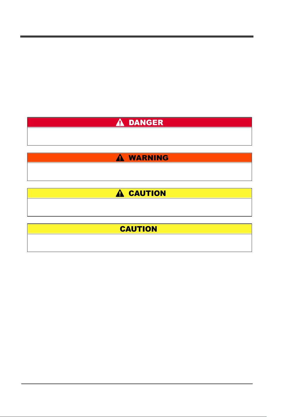
“WARNING”: Hazard that MAY cause serious personal injury or death during
operation.
“DANGER”: Hazard that WILL cause serious personal injury or death during
operation.
“CAUTION”: Hazard that MAY cause minor personal injury.
“CAUTION without exclamation symbol”: Hazard that MAY cause damage or failure
of the product, facility, devices, etc.
Chapter 1 Safety Instructions
1.3 Hazards
1.3.1 Level of hazards
The instructions given in this manual aim to assure the safe and correct
operation of the product, and to prevent injury of operators or damage to the
product. These instructions are grouped into three categories, Danger,
Warning and Caution, which indicate the level of hazard, damage and also
the degree of emergency. All safety critical information should be carefully
observed at all times.
“DANGER”, “WARNING” and “CAUTION” signs are in order according to
severity (DANGER> WARNING> CAUTION).
1.3.2 Definition of “Serious injury” and “Minor injury”
“Serious injury”
This term describes injuries that result in after effects including loss of
eyesight, burns, electric shock, fracture, poisoning, etc. and requires
long-term treatment or hospitalization.
“Minor injury”
This term describes injuries that do not need long-term treatment or
hospitalization. (Others excluded from “Serious injury”.)
1.3 Hazards HRSH Series
1-2
Page 11
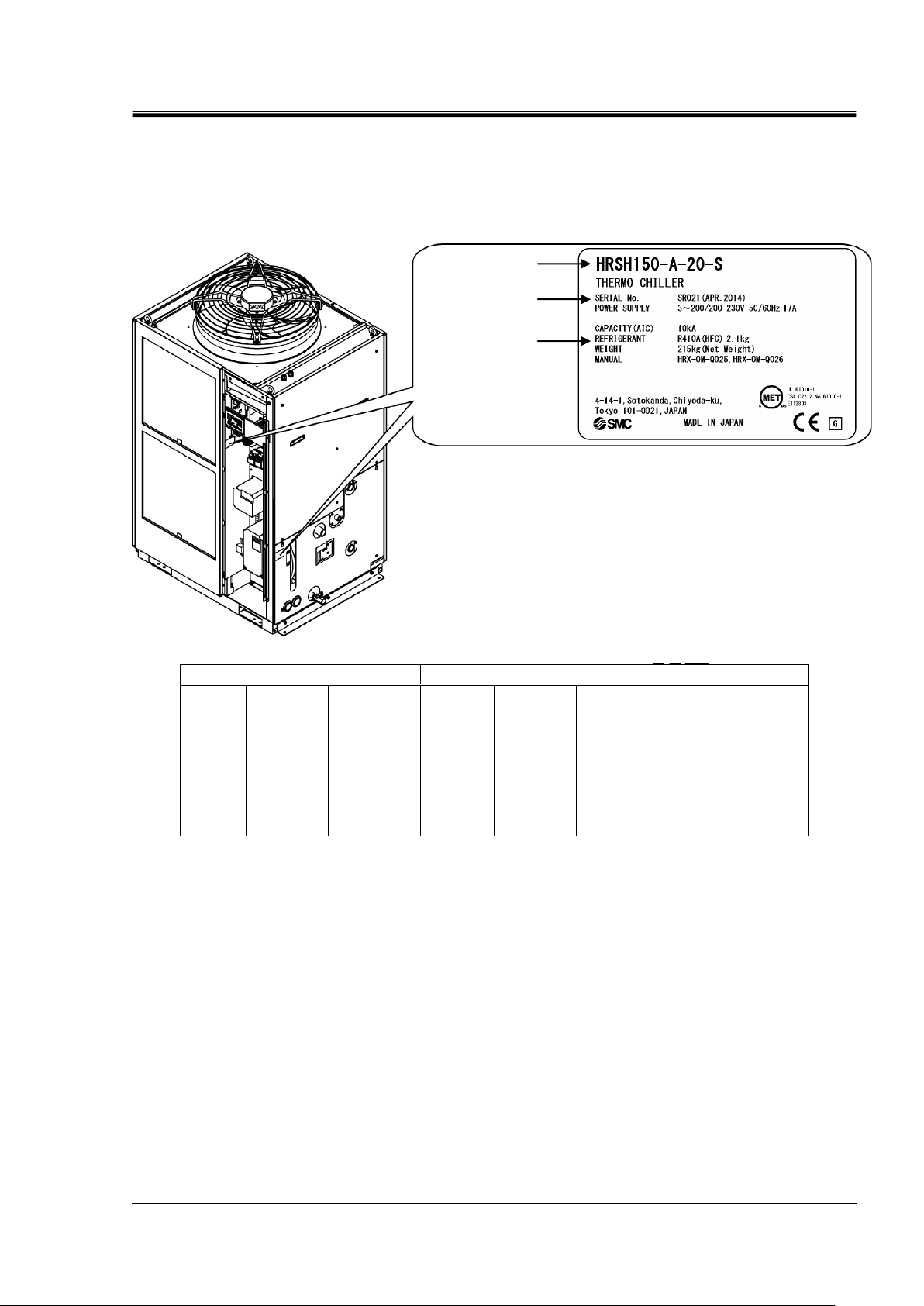
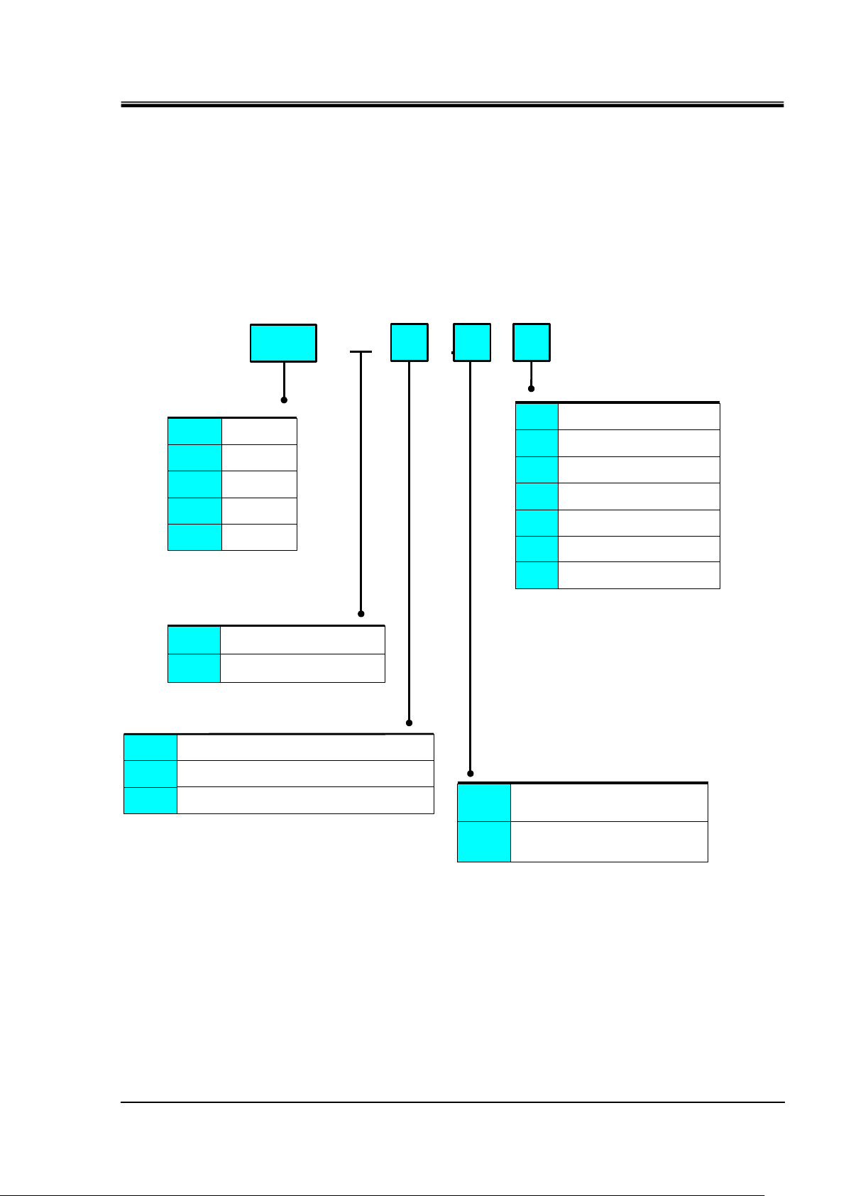
1.4 Product Label
Q
Z
001
Year
Symbol
Remarks
Month
Symbol
Remarks
Serial no.
2012
Q
Repeated
from
A to Z in
alphabetic
al
order
1
O
Repeated from
O to Z in
alphabetical
order, with O for
January and Z
for
December
-
2013 R 2 P 2014 S 3
Q
↓ ↓ ↓
↓
Kind and amount
of refrigerant
Model number
Serial number
* (An example of "HRSH150-A-20-S" model.)
"3~" stands for "3 inter phase".
(IEC 60417-5032-1)
Information about the product, such as Serial No. and Model No. can be
found on the product label. This information is needed when contacting an
SMC sales distributor.
How to see the serial number Q Z 001 (December 2012)
HRX-OM-Q026
Chapter 1 Safety Instructions
HRSH Series 1.4 Product Label
Fig. 1-1 Position of the product label
1-3
Page 12
HRX-OM-Q026
Follow the instructions below when using the product. Failure to
follow the instructions may cause an accident and injury.
Always use safety shoes and gloves when operating the product.
Always use safety shoes, gloves, mask, apron and eye protection
when handling the circulating fluid.
Always use safety shoes, gloves and head protection when
transporting, installing or uninstalling the product.
Chapter 1 Safety Instructions
1.5 Safety Measures
1.5.1 Safety instructions for use
● Read and understand this manual carefully before using the product.
● Before starting maintenance of the product, be sure to lock out and tag
out the breaker of the user's power supply.
● If operating the product during maintenance, be sure to inform all
workers nearby.
● Use only the correct tools and procedure when installing or maintaining
the product.
● Use personal protective equipment where specified (“1.5.2 Personal
protective equipment”).
● Check all parts and screws are fitted correctly and securely after
maintenance.
● Avoid working in a drunken or sick condition, which might cause an
accident.
● Do not remove the panels except for the cases permitted in this
manual.
● Do not remove the panels during operation.
● Do not handle this product by any means other than specified in this
Operation Manual; this can result in damage to the product or fire.
1.5.2 Personal protective equipment
This manual specifies personal protective equipment for each work.
Transport, Installing and Uninstalling
Handling of circulating fluid
Operation
1.5 Safety Measures HRSH Series
1-4
Page 13
1.6 Emergency Measures
Only maintenance personnel or qualified people are allowed to
open the cover panels of the product.
Do not mix the compressor oil with domestic waste for disposal.
Also, the disposal of the waste must only be conducted by specific
facilities that are permitted for that purpose.
Even when the power supply swtich is turned off, some of the internal
circuits are still energized, unless the user’s power supply is shut off.
Be sure to shut off the breaker of the user’s power supply.
Comply with the laws and regulations in each country for the
disposal of refrigerant and compressor oil.
The release of refrigerant in to the atmosphere is banned by law.
Recover it with specific equipment and dispose of it correctly.
Only people who have sufficient knowledge and experience about
the product and its accessories are allowed to recover the
refrigerant and compressor oil.
When emergency conditions such as natural disaster, fire, earthquake and
injury occur, shut off the breaker of the user’s power supply that supplies
power to the product.
1.7 Waste Disposal
1.7.1 Disposal of refrigerant and compressor oil
The product uses hydro fluorocarbon type refrigerant (HFC) and
compressor oil. Comply with the laws and regulations in each country for the
disposal of refrigerant and compressor oil. The type and quantity of
refrigerant is described on the “1.4 Product Label”.
If these fluids need to be recovered, read and understand the instructions
below carefully. If there is any unclear point, contact an SMC's sales
distributor.
1.7.2 Disposal of product
HRX-OM-Q026
Chapter 1 Safety Instructions
The disposal of the product must be handled by a specialized industrial
waste disposal agency in accordance with local laws and regulations.
HRSH Series 1.6 Emergency Measures
1-5
Page 14

HRX-OM-Q026
Chapter 1 Safety Instructions
1.8 Material Safety Data Sheet (MSDS)
If the material safety data sheets of chemicals used in this product are
needed, contact an SMC's sales distributor.
Any chemicals used by the user must be accompanied by an MSDS.
1.8 Material Safety Data Sheet (MSDS) HRSH Series
1-6
Page 15
HRX-OM-Q026
HRSH
①Cooling capacity
②Cooling method
③Piping thread type
④Power supply
- - -
⑤Option
A Air-cooled refrigeration
None
Nill
Caster-adjuster foot
installed
A
*2:Manual fluid fill port that is different from
the automatic fluid-fill function.
This enables that circulating fluid can be
filled manually without removing the side panel.
(In case of without K option, circulating
fluid can be filled manually removing
the side panel.)
Nil
Rc
F G (Rc-G thread adapter set is included)
N
NPT (Rc-NPT thread adapter set is included)
A
20
100 10kW
250
200 20kW
25kW
20
AC200V/200-230V(50/60Hz)
3phase
40
*3
AC380-415 50/60Hz 3phase
*1:In case of power supply '40' and option S,
this is standard. (with a handle)
W Water-cooled refrigeration
150 15kW
Earth leakage breakerB
*1
Fluid fill port
K
*2
Earth leakage breaker
with a handle
B1
*1
CE / ULS
*3
*3:Power supply '20' only.
300
*4
30kW
*4:Air coooled only
Fixed SI unitW
*4
*4: Unit : MPa/ ゜C (degree Celsius)
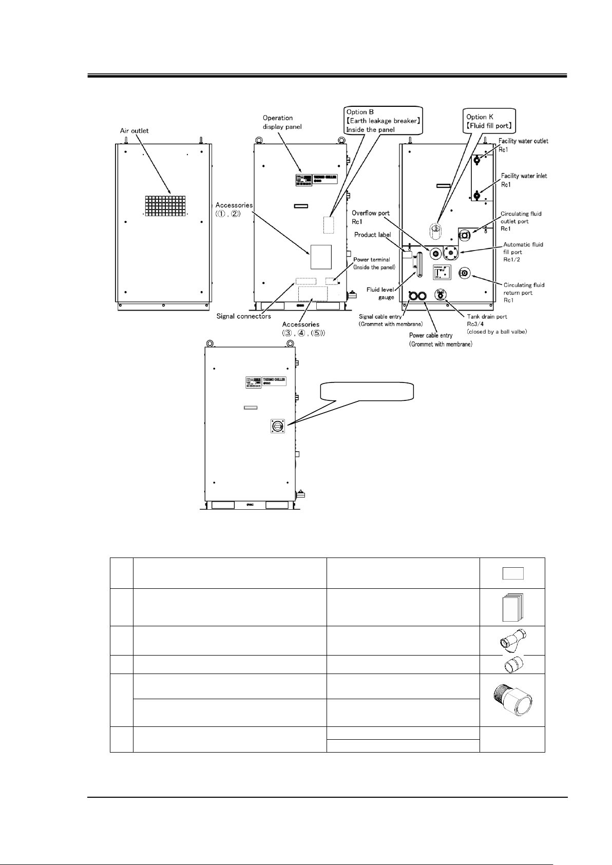
Chapter 2 Name and Function of Parts
Chapter 2 Name and Function of Parts
2.1 Model Number of Product
The product can be ordered with the model number configured as shown
below.
The product needs to be handled in different ways depending on the part
number. Refer to “1.4 Product Label" and check the part number of the
product.
Fig. 2-1 Product model number
HRSH Series 2.1 Model Number of Product
2-1
Page 16
HRX-OM-Q026
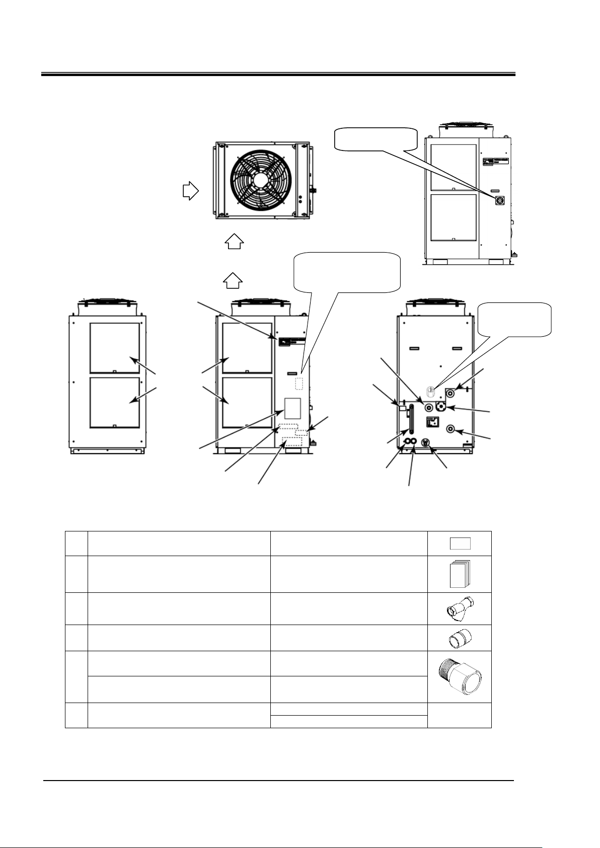
①
Alarm code list label
2 pcs.
(English 1 pc. /Japanese 1 pc.)
②
Operation manual
2 copies
(English 1 copy/Japanese 1
copy)
③
Y strainer (40 mesh) 25A
1 pc.
④
Barrel nipple 25A
1 pc.
⑤
For HRSH-AF-
G thread adapter set (HRS-EP014)
1 set
For HRSH-AN-
NPT thread adapter set (HRS-EP013)
1 set
-
Anchor brackets
2 pcs.
---
(M8 bolts)
6 pcs.
Circulating fluid
outlet port Rc1
Circulating fluid
return port Rc1
Automatic fluid
fill port Rc1/2
Overflow port
Rc1
Signal cable entry
(Grommet with membrane)
Tank drain port
Rc3/4 (closed by a
ball valve)
Power cable entry
(Grommet with membrane)
Product
Fluid level
gauge
Option K
[Fluid fill port]
Option B
[Earth leakage breaker]
Inside the panel
Dust-proof
Power terminal
(Inside the
Signal connectors
(Inside the panel)
Operation
display panel
Ventilation air inlet
Ventilation air inlet
Accessories
(③, ④, ⑤)
Accessories
(①, ②)
HRSH-A-20-B1
HRSH***-A*-20-S,
HRSH-A-40-
Breaker handle
Ventilation
air outlet
Chapter 2 Name and Function of Parts
2.2 Name and Function of Parts
2.2.1 HRSH-A- (Air cooled type)
Fig. 2-2 Names of the parts (This drawing shows “HRSH250-A-20”.)
Table 2-1: Accessory list
Note) The anchor brackets (including M8 bolts) are used for fixation with the skid when this product is packed. The anchor bolts are
not attached.
2.2 Name and Function of Parts HRSH Series
2-2
Page 17
2.2.2 HRSH-W- (Water cooled type)
①
Alarm code list label
2 pcs.
(English 1 pc. /Japanese 1 pc.)
②
Operation manual
2 copies
(English 1 copy/Japanese 1
copy)
③
Y strainer (40 mesh) 25A
1 pc.
④
Barrel nipple 25A
1 pc.
⑤
For HRSH-WF-
G thread adapter set (HRS-EP016)
1 set
For HRSH-WN-
NPT thread adapter set (HRS-EP015)
1 set
-
Anchor brackets
2 pcs.
---
(M8 bolts)
6 pcs.
Breaker handle
HRSH-W-20-B1
HRSH-W-20-S
HRSH-W-40-
Fig. 2-3 Names of the parts (This drawing shows “HRSH150-W-20”.)
Table 2-2: Accessory list
HRX-OM-Q026
Chapter 2 Name and Function of Parts
Note) The anchor brackets (including M8 bolts) are used for fixation with the skid when this product is packed.
The anchor bolts are not attached.
HRSH Series 2.2 Name and Function of Parts
2-3
Page 18

HRX-OM-Q026
Name
Function
Operation display panel
Runs and stops the product and performs settings such as the circulating
fluid temperature.
For details, refer to ’’2.4 Operation Display Panel’’.
Fluid level gauge
Indicates the circulating fluid level of the tank. Confirm the level is between
HIGH and LOW. For details, refer to “3.5 Circulating Fluid Supply”.
Product label
Shows the product information such as model number and serial number.
For details, refer to ‘’1.4 Product Label’.
Circulating fluid outlet port
The circulating fluid flows out from the outlet port.
Circulating fluid return port
The circulating fluid returns to the return port.
Tank drain port
This drain port to drain the circulating fluid out of the tank.
Automatic water fill port
Piping to the automatic water filling port enables easy supply of the
circulating fluid through the ball tap in the reservoir. The supply pressure
should be within the range of 0.2 to 0.5 MPa.
Overflow port
Be sure to connect piping from this port to sump pit to discharge the excess
circulating fluid that is caused by fluid level rising.
Dust-proof filter
Inserted to prevent that the dust and contamination are clung on the air
cooled condensers directly. Clean the filter periodically. For details, refer to
“7.2.2 Monthly check”.
Power cable entry
Insert the power cable to the power cable entry and connect it to the power
terminal. For details, refer to “3.3.2 Electrical wiring” and “3.3.3 Preparation
and wiring of power supply cable”.
Power terminal
Signal cable entry
Insert the signal cable to the signal cable entry and connect it to the signal
connectors. For details, refer to “3.3.4 Contact input/output communicatin
wiring”, “3.3.6 Wiring of run/stop signal input and remote signal input ”,
“3.3.8 Wiring of external switch signal input”, “3.3.9 Wiring of contact output
signal” , “3.3.8 RS-485 communication wiring” , “3.3.9 RS-232C
communication wiring” or the Operation Manual Communication Function.
Signal connecors
Earth leakage breaker
(When option B [Earth leakage
breaker] is selected.)
Shuts off the power supply to the internal equipment of the product.
(Parts energized remained in the product.)
Refer to “3.3.2 Electrical wiring” for the earth leakage breaker.
Breaker handle
(For HRSH***-A/W*-20-B1,
HRSH-A/W-20-S,
HRSH-A/W-40-)
Shuts off the power supply to the internal equipment of the product.
(Parts energized remained in the product.)
Refer to “3.3.2 Electrical wiring” for the earth leakage breaker.
Water fill port
(When option K “Water fill
port” is selected.)
Users who will not use the automatic water fill function can fill the circulating
fluid without removing the panel.
Facility water inlet port
(For water cooled type)
Supply facility water to the inlet port.
Facility water outlet port
(For water cooled type)
Facility water is discharged from the outlet port and returns to the user’s
facility water system.
Chapter 2 Name and Function of Parts
2.3 Function of Parts
The function of parts is as follows.
Table 2-3: Function of parts
2.3 Function of Parts HRSH Series
2-4
Page 19
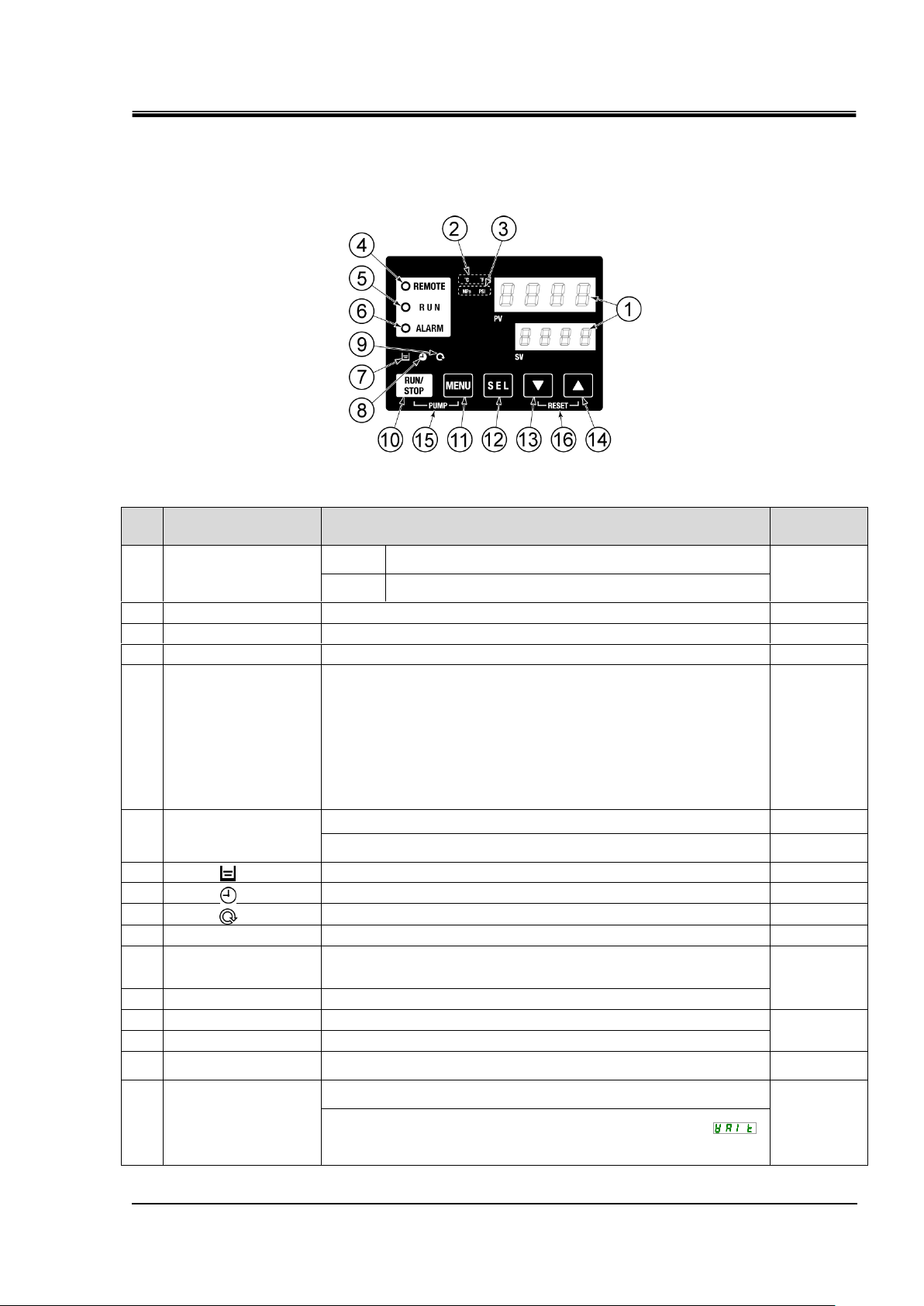
2.4 Operation Display Panel
No
Description
Function
Reference
page
①
Digital display
(7 segment,
4 digits)
PV
Displays the temperature and pressure of the circulating
fluid and alarm codes.
5.3
SV
Displays the set temperature of the circulating fluid and the
set values of other menus.
②
[oC oF] light
Displays the unit of display temperature (oC or oF).
5.13
③
[MPa PSI] light
Displays the unit of display pressure (MPa or PSI).
5.14
④
[REMOTE] light
Turns ON during remote operation by communication.
5.22
⑤
[RUN] light
・Turns ON when the product is started and in operation. Turns OFF
when the product stops.
・Blinks during stand-by for stop (Interval 0.5 seconds).
・Blinks during independent operation of the pump (Interval 0.3
seconds).
・Blinks while the anti-freezing function is being set (During standby:
Interval 2 seconds, During operation: Interval 0.3 seconds).
・Blinks during warming up function (During standby: Turns ON for 0.5
seconds and OFF for 3 seconds, During operation: Interval 0.3
seconds.)
4.4
⑥
[ALARM] light
Blinks with buzzer when alarm occurs (Interval 0.3 seconds).
5.4
Blinks while AL25 is OFF (Turns ON for 0.5 seconds and OFF for 3
seconds.)
5.21
⑦
[ ] light
Turns ON when the fluid level lowers below “L” (low) level.
4.3
⑧
[ ] light
Turns ON while the run timer or stop timer function is working.
5.7
⑨
[ ] light
Turns ON when the product is in automatic operation.
5.10
⑩
[RUN/STOP] key
Makes the product start or stop.
4.4
⑪
[MENU] key
Moves from the main menu (display which shows circulating fluid
temperature, pressure and etc.) to the other menus (entry of set
values and monitor screen).
5.2
⑫
[SEL] key
Changes the item in menu and enters the set value.
⑬
[▼] key
Decreases the set value.
-
⑭
[▲] key
Increases the set value.
⑮
[PUMP] key
When the [MENU] and [RUN/STOP] keys are held down
simultaneously, the pump starts running independently.
4.3
⑯
[RESET] key
Press the [▼] and [▲] keys simultaneously. This will stop the alarm
buzzer and turns OFF the [ALARM] light.
6.3
Keep the [▼] and [▲] keys pressed down simultaneously for 3
seconds to reset AL46 and AL48. (After resetting AL48, WAIT” ”
will be displayed and the product cannot start running for 40 seconds.
Restart 40 seconds later after resetting.
The operation panel on the front of the product controls the basic operation
of the product.
Fig. 2-4 Operation display panel
Table 2-4:Operation display panel
HRX-OM-Q026
Chapter 2 Name and Function of Parts
HRSH Series 2.4 Operation Display Panel
2-5
Page 20

HRX-OM-Q026
Chapter 2 Name and Function of Parts
2.4 Operation Display Panel HRSH Series
2-6
Page 21
HRX-OM-Q026
Drain the residual fluid from the piping as much as possible to
prevent any spillage.
Only persons who have sufficient knowledge and experience about
the product and system are allowed to transport and set up the
product.
Especially pay attention to personal safety.
Never lay the product on its side.
The compressor oil will leak in to the refrigerant piping, which may
cause early failure of the compressor.
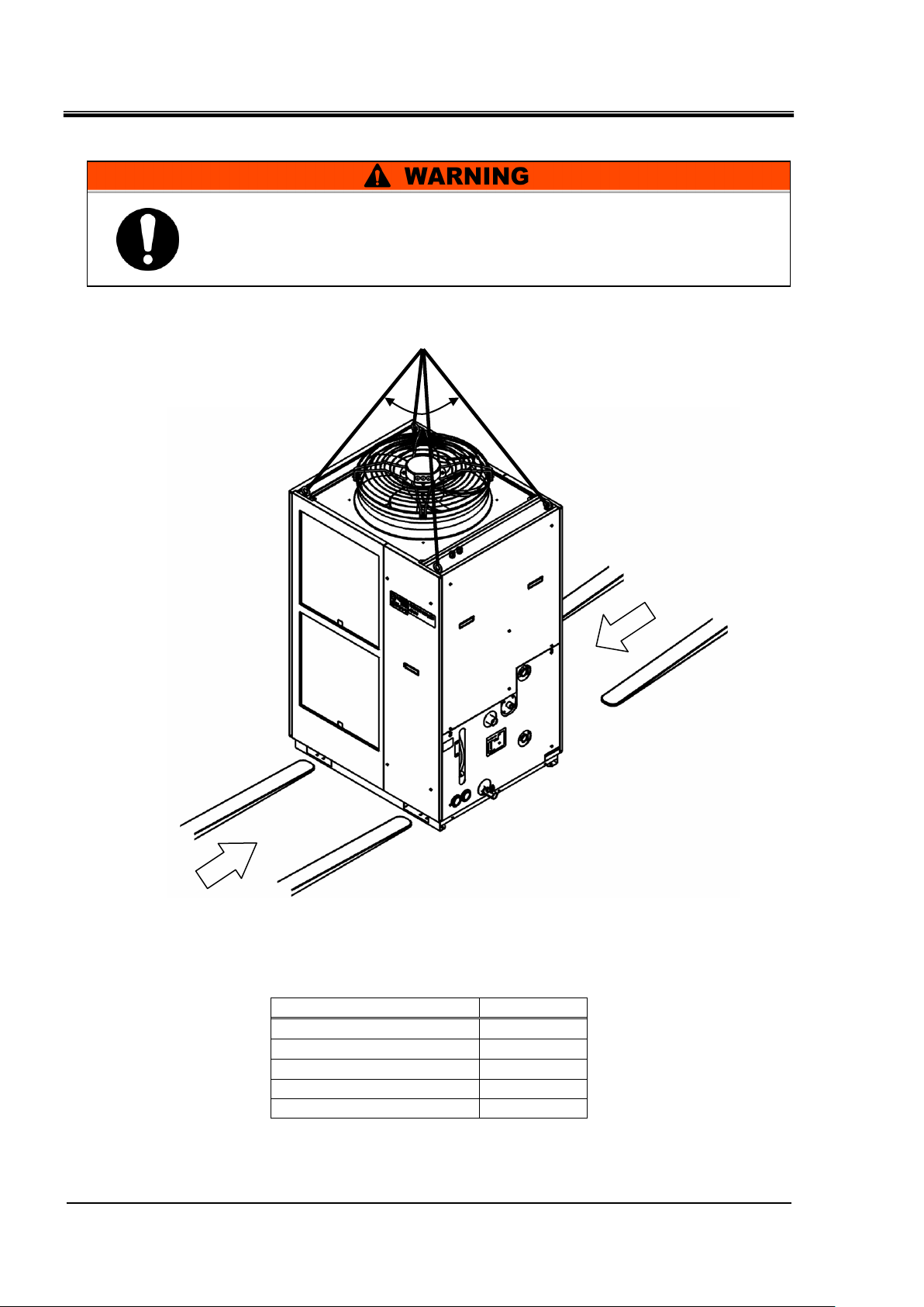
When the product is carried by using a forklift, make sure that the
fork does not damage the cover panel or piping port.
Be sure to use all the four eye bolts when slinging the product.
The slant angle of each rope should be 60 degrees or less.
When moving the product by a forklift, insert the fork into the right
positions referring to 3.1.1 Transportation using forklift and
hanging- Moving by forklift and slinging should be done by
persons who have the licenses.
Chapter 3 Transport and Setting Up
Chapter 3 Transport and Setting Up
3.1 Transport
The product is heavy and has potential danger at transport. Also, to prevent
damage and breakage of the product, be sure to follow the instructions
shown below for transport.
HRSH Series 3.1 Transport
3-1
Page 22
HRX-OM-Q026
Model
Weight kg
HRSH250/300-A-
Approx. 280
HRSH150/200-A-
Approx. 215
HRSH100-A-
Approx. 180
HRSH150/200/250-W-
Approx. 180
HRSH100-W-
Approx. 150
This is a heavy product. (Refer to
Table 3-1 Weight of the product) Moving by forklift and slinging should be
done by persons who have the licenses.
Position to hang
60o or less
Fork inserting position
Fork inserting position
Chapter 3 Transport and Setting Up
3.1.1 Transportation using forklift and hanging
Fig. 3-1 Fork inserting and hanging position (This drawing shows “HRSH250-A-20”.)
Table 3-1 Weight of the product
3.1 Transport HRSH Series
3-2
Page 23
HRX-OM-Q026
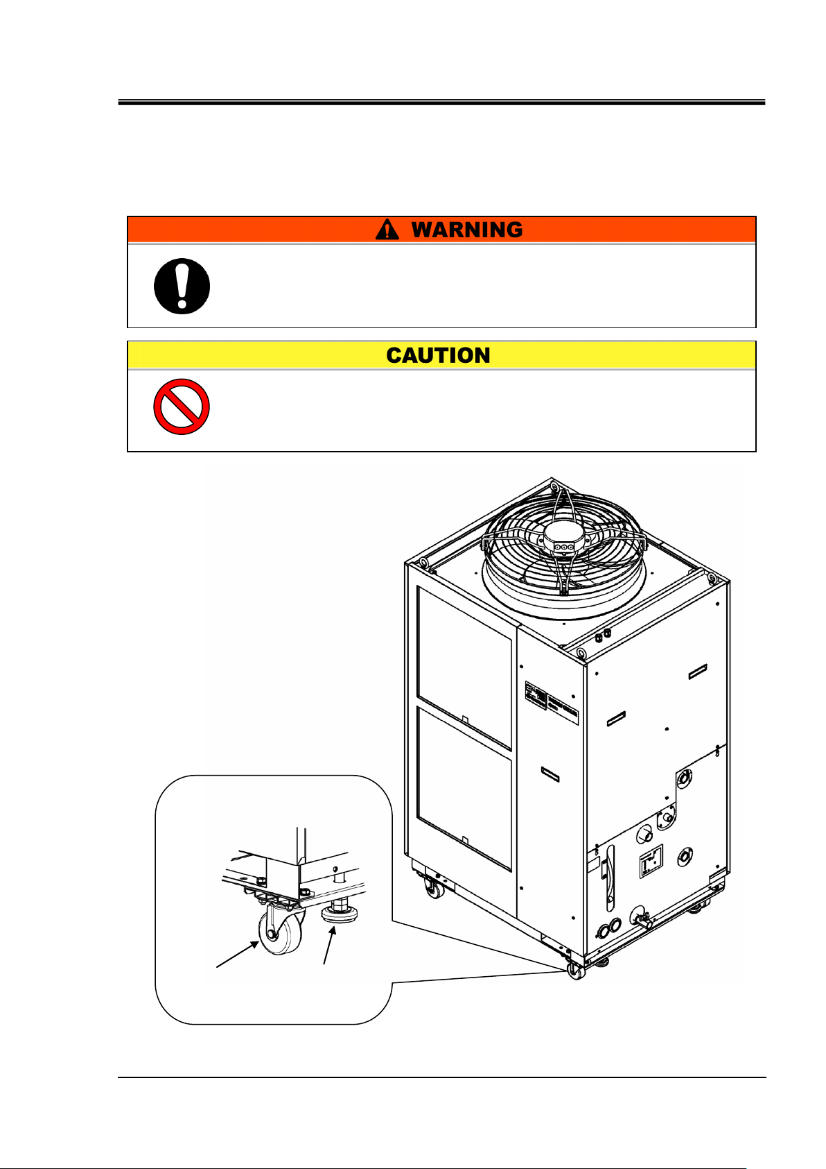
Raise the adjuster
foot.
Swivel
caster
Each swivel caster can
rotate 360 degrees freely.
Raise the adjuster feet and push the corners of the product when
moving the product using the casters.
Do not hold the piping connections or handles of the panels when
moving by casters, or it may cause damage to the product..
This is a heavy product. (Refer to Table 3-1 Weight of the product).
Moving the product by casters should be done by 2 persons or more.
Chapter 3 Transport and Setting Up
3.1.2 Transportation using casters
In case of purchasing option A or the optional accessories, “Caster
Adjuster-foot kit” (HRS-KS001/KS002) separately and after fastening it to
the product.
Fig. 3-2 Transportation using casters (This drawing shows “HRSH250-A-20”.)
HRSH Series 3.1 Transport
3-3
Page 24
HRX-OM-Q026
Keep the product upright on a rigid and flat floor which can resist
the weight of the product, and take measures to prevent the
product from tipping over. Improper installation may cause water
leakage, tipping, damage of the product or injure the operator.
Keep the ambient temperature of the product between -20 to 45oC.
Operation out of this ambient temperature range may cause a
malfunction of the product. Operating the product in an
environment temperature of 45 oC may reduce the heat
discharging efficiency of the heat exchanger and the safety device
may function, resulting in the product operation stoppage.
The installer/end user is responsible for carrying
out an acoustic noise risk assessment on the equipment after
installation and taking appropriate measures as required.
Do not set up the product in places possibly exposed to leakage of
flammable gas. Should any flammable gas stay around the
product, the product may cause a fire.
Chapter 3 Transport and Setting Up
3.2 Installation
3.2.1 Environment
The product must not be operated, installed, stored or transported in the
following conditions. Potential malfunction or damage to the product may
occur if these instructions are disregarded.
This product is not designed for clean room usage. The pump and
ventilating fan inside the product generate particles.
● Location that is exposed to steam, salt water or oil.
● Location that is exposed to dust or powder material.
● Location that is exposed to corrosive gas, organic solvent, chemical
solution, or flammable gas. (The product is not explosion-proof.)
● Location where the ambient temperature is out of the following range:
During transportation or storage: -15 to 50°C (No water or circulating
fluid in the piping.)
During operation Air cooling type: -20 to 45°C
Water cooling type: 2 to 45°C
When the ambient temperature or circulating fluid temperature is
10oC or below, use the circulating fluid specified in "3.2.2 Operation
at low ambient temperature or low circulating fluid temperature".
● Location where condensation forms on the inside electrical parts.
● Location that is exposed to direct sunlight or heat radiation.
● Location that is near heat sources and poor in ventilation.
● Location that is subjected to abrupt changes in temperature.
● Location that is subjected to strong electromagnetic noise (intense
electric field, intense magnetic field, or surges).
● Location that is subjected to static electricity, or conditions where static
electricity can discharge to the product.
● Location that is subjected to strong high frequencies raditation.
● Location that is subjected to potential lightening srtike.
● Location at altitude of 3000m or higher (except during product storage
and transport). Refer to below for details.
● Location where the product is affected by strong vibrations or impacts.
3.2 Installation HRSH Series
3-4
Page 25
Chapter 3 Transport and Setting Up
Altitude [m]
1. Max. ambient
temp. [oC]
2. Cooling capacity
correction coefficient
Less than 1000m
45
1.00
1000 m or more - Less than 1500 m
42
0.85
1500m or more - Less than 2000m
38
0.80
2000m or more - Less than 2500m
35
0.75
2500m or more - Less than 3000m
32
0.70
● Condition that applies external force or weight causing the product to
be damaged.
● Location without adequate space for maintenance as required.
● Location that is exposed to splash of water that is higher than IPX4.
● When the ambient temperature or circulating fluid temperature is 10°C
or below, use the circulating fluid specified in "3.2.2 Operation at low
ambient temperature or low circulating fluid temperature".
● For the product installation or operation in accordance with UL
standards, see below.
Thermo-chiller installation in high altitude of 1000 meters or more
Because of lower air density, the heat radiation efficiencies of the devices in
the product will be lower in the location at altitude of 1000m or higher. For
this reason, the maximum ambient temperature for the thermo-chiller
operation and the cooling capacity will be reduced.
For product installation at a place of high altitude of 1000 meters or more,
select a thermo-chiller of the applicable capacity referring to the table below.
1. Max. ambient temp.: Use the product in lower ambient temperature than
the described value at each altitude.
2. Cooling capacity correction coefficient: Coefficient to calculate the cooling
capacity at each altitude
HRX-OM-Q026
For the product operation at an altitude of 1800 meters, the cooling capacity
at an altitude of 1800 meters = Cooling capacity 8.4 x 0.8.
Installation/Operation in accordance with the UL standard (for the optional UL
compliant model)
For operation of the UL compliant model (available as an option,
HRSH***-*-20-*S*) in UL compliant conditions, the product cannot be used
in the environment shown below:
● Environment at an altitude of 2000 meters or more
● Environment at a pollution degree of 3 or more
● Location where the ambient humidity is out of the following range:
During transportation or storage: 15% to 85% (No condensation)
During operation: 30% to 70% (No condensation)
HRSH Series 3.2 Installation
3-5
Page 26
HRX-OM-Q026
Ambient temperature (°C)
Recommended circulating fluids
10 to 45
Tap water, ethylene glycol aqueous solution 15(wt)%
-5 to 10
Ethylene glycol aqueous solution 15(wt)%
-20 to -5
Ethylene glycol aqueous solution 40(wt)%
Circulating fluid
temperature(°C)
Recommended circulating fluids
10 to 35
Tap water, ethylene glycol aqueous solution 15(wt)%
5 to 10
Ethylene glycol aqueous solution 15(wt)%
Chapter 3 Transport and Setting Up
3.2.2 Operation at low ambient temperature or low circulating fluid
temperature
(1) Circulating fluid
In order to avoid freezing of the circulating fluid, use aqueous solution of ethylene glycol.
Note 1) Concentration has to be 40(wt)% or less.
If the concentration is higher than 40(wt)%, pump will be overloaded.
Note 2) When 40% ethylene glycol aqueous solution is used, cooling capacity decreases
by 20%.
(2) And following instructions must be executed. If following instructions are not executed, not
only Thermo-chiller alarm will be generated, but also damage of the product can result.
- Power has to be supplied to the Thermo-chiller all the time.
- Turn on anti-freezing function (set parameter: SE.10) all the time.
- When the power supply to the Thermo-chiller is stopped for a long period of time,
discharge all the circulating fluid in the Thermo-chiller and customer's device and
piping. When the Thermo-chiller is refilled with the circulating fluid, supply the fluid
at normal temperature.
3.2 Installation HRSH Series
3-6
Page 27
3.2.3 Location
Model
Heat
radiation
(kW)
Required ventilation amount (m3/min)
Differential temp. of
3 oC between inside
and outside of
installation area
Differential temp. of
6 oC between inside
and outside of
installation area
HRSH100-A-20/40-
Approx.18
305
155
HRSH150-A-20/40-
Approx.29
490
245
HRSH200-A-20/40-
Approx.35
590
295
HRSH250-A-20/40-
Approx.44
730
370
HRSH300-A-20/40-
Approx.45
760
380
Do not install in a location which can be subjected to any of the
conditions in “3.2.1 Environment”.
The air cooled product radiates heat from the air vent of the cooling fan.
If the product is operated with insufficient air ventilation the internal
temperature can exceed 45oC, which can cause and affect the
performance and life of the product. To prevent this ensure that
suitable ventilation is available (see below).
Installation of multiple products
Keep sufficient space between products so that the air vented from one
product will not be taken in by other products.
Installation at indoor site (for air cooled type)
HRX-OM-Q026
Chapter 3 Transport and Setting Up
1. For a facility having a large installation area (that can vent the air
naturally):
Make an air outlet on a wall at a high level and air inlet on a wall at a low
level, to allow for adequate airflow.
2. For a facility having a small installation area (that can not vent the air
naturally):
Make a forced air exhaust vent on a wall at a high level and an air inlet on a
wall at a low level.
3. Using duct to exhaust the air:
In case the indoor site cannot accept the exhausted air from the product
or/and is air conditioned, ventilate by installing a duct on the outlet
ventilation of the product. Do not fasten the duct on the outlet ventilation of
the product directly. Have the space at least the duct’s diameter apart. Use
a fan for the duct that considered the ventilation resistance of the duct.
Table 3-2 Amount of radiation and required ventilation
HRSH Series 3.2 Installation
3-7
Page 28
HRX-OM-Q026
Model
Heat
radiation
(kW)
Facility water specifications
HRSH100-W-20/40-
Approx. 20
Refer to “8.1 Specifications”.
HRSH150-W-20/40-
Approx. 27
HRSH200-W-20/40-
Approx. 34
HRSH250-W-20/40-
Approx. 40
The water cooled product radiates heat to the facility water.
It is necessary to supply the facility water. Please prepare the facility
water system that satisfies the heat radiation and the facility water
specifications below.
Chapter 3 Transport and Setting Up
Required facility water system (for water cooled type)
Table 3-3 Heat radiation
Installation at indoor site
The product’s splash-proof specification is IPX4.
Installation environment specifications
Sound noise:HRSH300-A- : 71dB(A)
HRSH100/150/200/250-A- : 68dB(A)
HRSH150/200-W- : 60dB(A)
HRSH100/250-W- : 61dB(A)
* Front 1m, height 1m, rated condition
3.2 Installation HRSH Series
3-8
Page 29
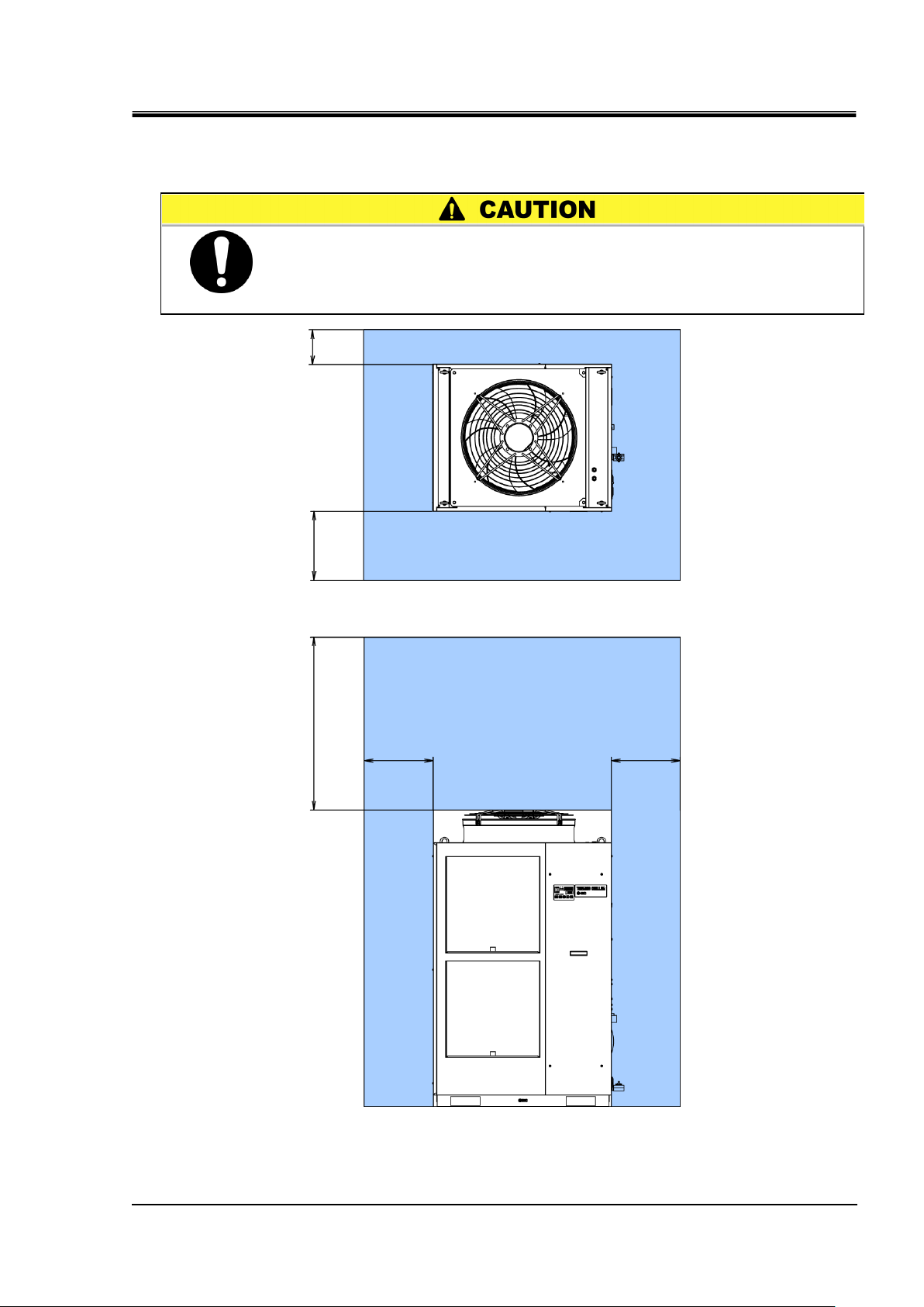
3.2.4 Installation and maintenance space
Have an enough space for the ventilation for the product. Otherwise it
may cause a lack of cooling capacity or/and stoppage of the product.
Ensure there is enough space for maintenance.
Top
Front
800mm or more
(For water cooled type)
400mm or more
800mm or more
2000mm or more
800mm or more
800mm or more
It is recommended to keep the space around the product shown in Fig. 3-3.
Fig. 3-3 Installation space (This drawing shows “HRSH250-A-20”.)
HRX-OM-Q026
Chapter 3 Transport and Setting Up
HRSH Series 3.2 Installation
3-9
Page 30
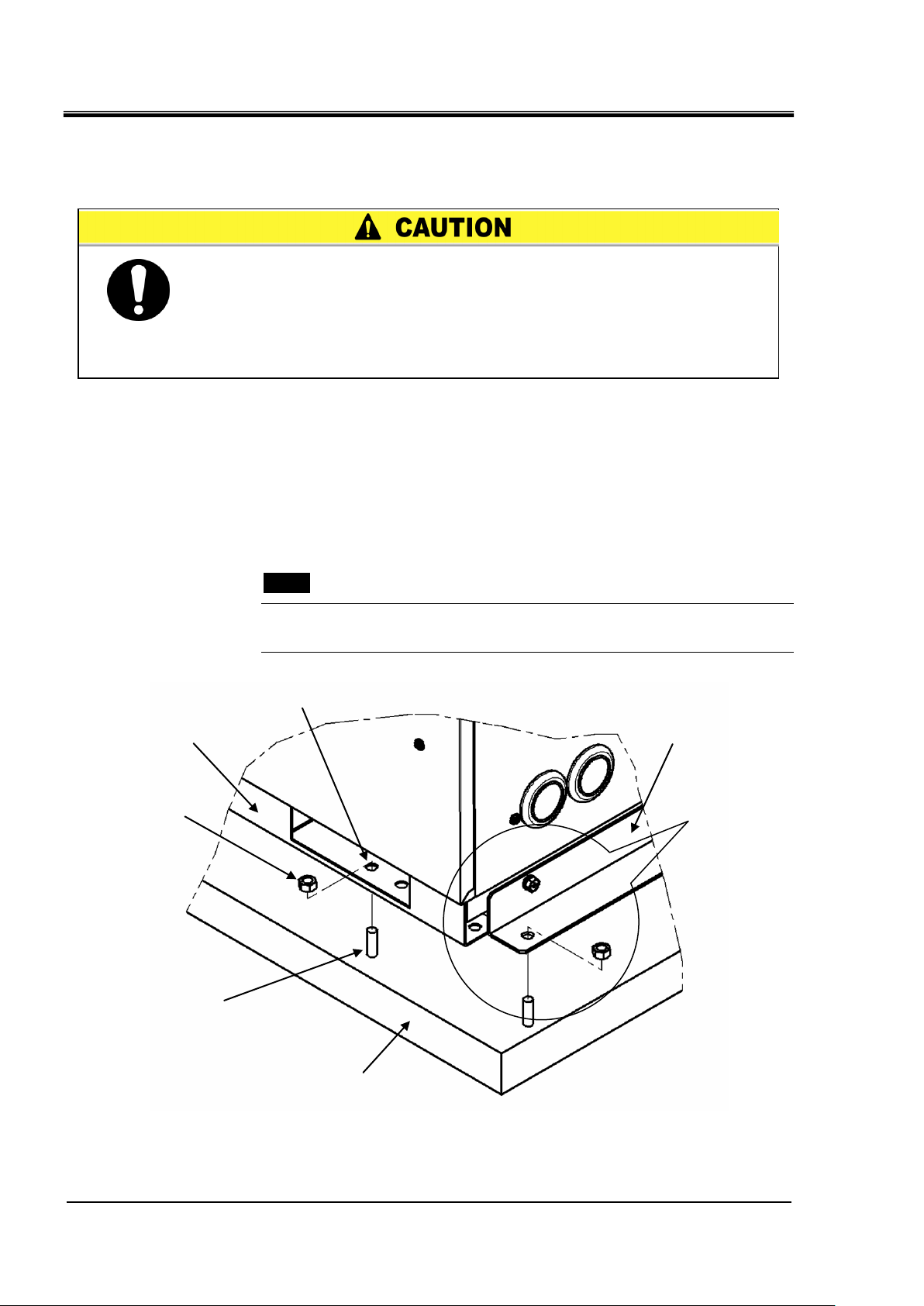
HRX-OM-Q026
Install the product on a vibration free level floor.
Prepare the M10 anchor bolts that are suitable for the material of the
floor that the product will be installed on. Drive the anchor bolts in at
least two places on the left and right sides of the product (four places
in total). Refer to “8.2 Dimensions” for the dimensions for the position
of the anchor bolts.
Floor
Anchor bolt
Nut
Base of the product
Hole for anchor bolt (12mm)
Anchor bracket
Hole for anchor
bolt (12mm)
Chapter 3 Transport and Setting Up
3.3 Installation
3.3.1 Installation
How to mount the product
1. Insert the product to the anchor bolts that were previously driven on the level floor.
2. Fasten the nuts to the anchor bolts.
3. Make sure that there is no looseness on all the anchor bolts and nuts.
[Tips]
SMC Foundations bolt set “IDF-AB500” (SUS M10x50mm) is applicable.
Please order separately.
Fig. 3-4 Installation procedures
3.3 Installation HRSH Series
3-10
Page 31

HRX-OM-Q026
In case of using “Caster Adjuster-foot kit”, be sure to use the adjuster
foot to install on the floor. The adjuster foot is not earthquake-proof.
If necessary make an earthquake-resistant measure on the customer
side.
Lower the adjuster to the level floor
to fix the product in place.
Caster
Chapter 3 Transport and Setting Up
Option A or “Caster Adjuster-foot kit” (HRS-KS001/KS002)
Refer to the Operation Manual for the separately sold accessory for the further details of the swivel
caster and the adjuster foot set.
Fig. 3-5 Installation by adjuster foot
HRSH Series 3.3 Installation
3-11
Page 32

HRX-OM-Q026
Do not modify the internal electrical wiring of the product. Incorrect
wiring may cause electric shock or fire. Also, modifying the
internal wiring will void the product’s warranty.
NEVER connect the ground to water line, gas pipe or lightning
conductor.
The installation of electrical equipment and wiring work should be
performed only by personnel with sufficient knowledge and
experience.
Be sure to shut off the user’s power supply. Wiring with the
product energized is strictly prohibited.
The wiring must be conducted using cables complying with “Table
3-4” and firmly secured to the product to prevent the external force
of cables being applied to the terminals. Incomplete wiring, or
improper securing of wiring, may cause electrical shock or
excessive heat and fire.
Ensure a stable power supply with no voltage surges.
Ensure that an earth leakage breaker is used in the power supply of
the product. See “Table 3-4”.
Use a power supply suitable for the specifications of the product.
Use a power supply of over voltage category 3 (IEC60664-1)*.
Be sure to connect the ground connection.
Ensure that a lock out facility is availble on the power supply.
Each product must have its own separate earth leakage breaker.
Otherwise there can be a risk of electric shock or fire.
Ensure that no harmonics are superimposed at power supply.
(Do not use inverter, etc.)
Supply a steady power supply which is not affected by surges or
distortion. In particular, if the voltage rate of increase (dv/dt) at
zero crossing exceeds 40V/200μsec, it may cause malfunction.
V
dV
dt
dt
= Voltage ratio
on zero-cross point
dV
t
Voltage rise %
Time
Voltage
Chapter 3 Transport and Setting Up
3.3.2 Electrical wiring
*: For the users that purchased Option S for the product operation in the UL compliant conditions,
please refer to "Installation/Operation in accordance with the UL standard" in the next page.
3.3 Installation HRSH Series
3-12
Page 33

HRX-OM-Q026
Model
Power
supply
voltage
Terminal
block
screw
diameter
Recommend
ed crimp
terminal
Cable
specifications*2
Earth leakage
breaker *1
Rated
current
(A)
Sensitivity
of
leakage
current
(mA)
HRSH100-A-20-
HRSH100-W-20-
200 VAC/
200-230
VAC
50/60Hz
3 phase
M5
R5.5-5
4 cores x
AWG10
(4 cores x 5.5 mm2)
*including
ground
30
30
HRSH150-A-20-
HRSH150-W-20-
HRSH200-A-20-
HRSH200-W-20-
R8-5
4 cores x AWG8
(4 cores x 8 mm2)
*including
ground
40
HRSH250-A-20-
HRSH250-W-20-
HRSH300-A-20-
50
HRSH100-A-40-
HRSH100-W-40-
380-415
VAC
50/60Hz
3 phase
M5
R5.5-5
For power
line
3 x 5.5 mm2
(3 x AWG10)
20
30
HRSH150-A-40-
HRSH150-W-40-
30
HRSH200-A-40-
HRSH200-W-40-
R14-5
For ground
line
1 x 14 mm2
(1 x AWG6)
Ground line
HRSH250-A-40-
HRSH250-W-40-
HRSH300-A-40-
Chapter 3 Transport and Setting Up
Power supply specifications, power supply cable and earth leakage breaker
Prepare the power supply shown in the following table. For the connection between the product and
power supply, use the power supply cable and earth leakage breaker shown below. An earth leakage
breaker must be mounted to a position where the breaker is easily accessible and close to the
thermo-chiller.
Table 3-4 Power supply cable and earth leakage breaker (Recommended)
*1. A specified earth leakage breaker is installed for option B, option B1, option S of each model. If
the product is not option B, option B1, option S, please prepare an earth leakage breaker on the
user’s side. A specified earth leakage breaker and handle are installed for HRSH--40-
*2. Cable specifications are the examples when using the product at a continuous allowable
operating temperature of 70 oC, with an operating voltage of 600 V and two kinds of plastic
insulated wires at an ambient temperature of 30 oC. Please select the proper size cables
according to the actual condition.
Installation/operation in accordance with the UL standard (for the optional UL
compliant model)
For operation of the UL compliant model (available as an option, HRSH--20-S) in the UL
compliant conditions, the conditions shown below must be satisfied:
- Use power supply of overvoltage category 2 (transient overvoltage 2500 V
or less) *1.
- Bending radius of the power supply cable must be 38.1 mm or more.
*1. When using a power supply in the overvoltage category 3, take measures such as mounting an
isolation transformer between the product and the power supply or keep the transient
overvoltage of the power supply to 2500 V or less by using a varistor, etc.
HRSH Series 3.3 Installation
3-13
Page 34

HRX-OM-Q026
Be sure to lock out and tag out the breaker of the facility power supply
(customer power supply facility) before wiring.
The electrical facilities should be installed and wired in accordance
with local laws and regulations of each country and by a person
who has knowledge and experience.
Check the power supply. Operation with voltages, capacities and
frequencies other than the specified values can cause fire and
electric shock.
Wire with an applicable cable size and terminal. Forcibly mounting
with an unsuitably size cable may result in heat generation or fire.
Be sure to connect the power supply cable from the product side first,
and then connect the breaker of the facility power supply (the user’s
machine power supply).
When the panel is removed or mounted, be sure to wear protective
shoes and gloves to prevent injury with the edge of the panel.
Chapter 3 Transport and Setting Up
3.3.3 Preparation and wiring of power supply cable
3.3 Installation HRSH Series
3-14
Page 35

A breaker that has the operating characteristic below is installed. Please use a
breaker that has the same or longer operating time as/than this for the customer
side (upstream side). If it has a shorter operating time, there is a possibility of
accidental breaker trip due to the internal motors’ inrush currents of this product.
4h
2h
1h
30min
20min
14min
10min
6min
4min
2min
1min
30s
20s
10s
5s
2s
1s
0.5s
0.2s
0.1s
0.05s
0.02s
0.01s
100 135 200 300 400 500600700 1000 1500 2000 3000 4000
Current (% for breaker capacity)
Operating time
Min.
Max.
HRX-OM-Q026
Chapter 3 Transport and Setting Up
Option B “Earth leakage breaker”, option B1 “Earth leakage breaker with
handle”, and HRSH--40-
Operating characteristics of the breaker
HRSH Series 3.3 Installation
3-15
Page 36

HRX-OM-Q026
Screw
Front panel for the
electrical unit
For HRSH-A-20-B1,
HRSH-A-20-S,
HRSH-A-40-
OFF
Note: Turn off the earth
leakage breaker. The
front panel of the
electrical unit cannot
be removed without
turning off the breaker.
Front panel
Screw
For HRSH-W-20-B1,
HRSH-W-20-S,
HRSH-W-40-
Note: Turn off the earth
leakage breaker. The
front panel of the
electrical unit cannot
be removed without
turning off the breaker.
OFF
Chapter 3 Transport and Setting Up
Preparation for operation
1. Remove four screws to remove the front panel for the electrical unit.
Fig. 3-6 Remove the front panel for the electrical unit (This drawing shows air cooled type.)
Fig. 3-7 Remove the front panel for the electrical unit (This drawing shows water cooled type.)
3.3 Installation HRSH Series
3-16
Page 37

HRX-OM-Q026
Handle
View A
Handle
View A
Chapter 3 Transport and Setting Up
2. Hold the handle and pull up the front panel of the electrical unit, and remove it.
Fig. 3-8 Remove the front panel for the electrical unit (This drawing shows air cooled type.)
Fig. 3-9 Remove the front panel of the electrical unit (This drawing is water cooled type.)
HRSH Series 3.3 Installation
3-17
Page 38

HRX-OM-Q026
Inlet of the
power supply cable
Note: Prepare a cable tie.
Fasten the power cable to the
mount on the base with the
cable tie.
View A
L1 L2 L3 PE
Mount for cable tie
Chapter 3 Transport and Setting Up
3. Connect the power supply cable and the ground cable as shown in the figure below.
Fig. 3-10 Wiring of power supply cable
* Connect an over current protection to the power cable connected to the equipment to avoid hazard.
3.3 Installation HRSH Series
3-18
Page 39

Chapter 3 Transport and Setting Up
Terminal specification
Cable specification
Terminal block
screw diameter
Recommended
crimp terminal
M3
Y style crimp
terminal
1.25Y-3
0.75 mm2 (AWG18)
Shielded cable
Be sure to lock out and tag out the breaker of the facility power supply
(the user’s machine power supply) before wiring.
Use the cable and terminal that are specified.
The capacity of the output contact of the product is limited. If the capacity is not
large enough, install a relay, etc. (to allow for larger capacity). Also, ensure that the
input current of the relay is small enough in relation to the contact capacity of the
product.
3.3.4 Contact input/output communicatin wiring
The product has a contact input/output communication function as shown
below. Connect cables referring to the applicable chapter for each function.
(For details of the functions, refer to Operation Manual Communication
Function.)
● Run/Stop input・Remote signal input (Refer to “3.3.5 Wiring of run/stop
signal input and remote signal input”)
● External switch signal input (Refer to “3.3.6 Wiring of external switch
signal input”)
● Output of contact output signal (Refer to “3.3.7 Wiring of contact output
signal Wiring of contact output signal”)
HRX-OM-Q026
Use the signal cable described below for wiring of each function.
Signal cable
Use the cable and terminals as shown below for wiring of each function.
Table 3-5 Signal cable
3.3.5 Wiring of run/stop signal input and remote signal input
Run/Stop signal input and remote signal input enable the product to
operate/stop or switched DIO REMOTE and DIO LOCAL remotely by
applying a contact signal input. This chapter illustrates examples of wiring.
Select DIO mode as the communication mode to activate the run/stop signal
input and remote signal input after wiring referring to Operation Manual
Communication Function.
[Tips]
This product has two input signals. These can be customized depending on
the customer’s application.
HRSH Series 3.3 Installation
3-19
Page 40

HRX-OM-Q026
Name
Terminal No.
Specification
Power supply
output
5, 6, 7
(24 VDC)
24 VDC ±10 % 500 mA MAX*1
13,14, 15
(24 V COM)
Contact input
signal 1
3
(Contact input signal 1)
- Run/Stop signal input
- External switch signal
input*2
Switch the input on the
operation display panel.
Refer to the Operation
Manual Communication
Function for details.
11
(Common of contact input signal 1)
Contact input
signal 2
4
(Contact input signal 2)
- Run/Stop signal input
- Remote signal input
- External switch signal
input*2
12
(Common of contact input signal 2)
Chapter 3 Transport and Setting Up
Table 3-6 Power supply, contact specifications
*1: To use the power of the device, the total load current must be 500 mA or less.
If the load is 500 mA or more, the internal fuse will blow to protect the product and the alarm “AL21 DC
line fuse cut” will be generated. Refer to Chapter 6 Alarm Notification and Troubleshooting.
*2: Refer to “3.3.6 Wiring of external switch signal input.
1. Prepare the switch (power supply voltage: 24 VDC, contact capacity: 35 mA or more,
minimum load current: 5mA), and a signal cable. (See “Table 3-5 Signal cable)
3.3 Installation HRSH Series
3-20
Page 41

HRX-OM-Q026
Inlet of the signal
cable
Note: Prepare a cable tie.
Fasten the signal cable to the
mount on the base with the
cable tie.
Terminal No. 5
Terminal No.13
Terminal No.11
Switch
Mount for cable tie
Terminal No. 3
Chapter 3 Transport and Setting Up
2. Connect the signal cable and switch to the terminal as shown below. (This wiring is an
example. Refer to Operation Manual Communication Function for more details.)
HRSH Series 3.3 Installation
Fig. 3-11 Wiring of run/stop signal input and remote signal input (Example)
3-21
Page 42

HRX-OM-Q026
Name
Terminal No.
Specification
Power supply output
5, 6, 7 (24 VDC)
24 VDC ±10% 500 mA MAX*1
13,14, 15 (24 V COM)
Contact input signal 1
3 (Contact input signal 1)
NPN open collector output
PNP open collector output
(Refer to the Operation Manual
Communication Function for details)
11 (Common of contact input signal 1)
Contact input signal 2
4 (Contact input signal 2)
12 (Common of contact input signal 2)
Communication mode *1
Contact input signal 1
Contact input signal 2
Local mode
✓
✓
SERIAL mode
MODBUS
✓
✓
Simple communication
protocol 1
✓
✓
Simple communication
protocol 2
x
✓
DIO mode *2
✓
x
x
✓
Description
Manufacturer
Part No.
Output type
Current
consumption
Flow switch
SMC
PF3W721□-□□-A□(-M)
NPN open collector
output
50 mA or less
PF3W721□-□□-B□(-M)
PNP open collector
output
50 mA or less
Be sure to turn OFF the breaker of the facility power supply (the
user's machine power supply) before wiring.
Chapter 3 Transport and Setting Up
3.3.6 Wiring of external switch signal input
This product can be monitored by sampling the signal of the external switch
prepared by the user.
Table 3-7 Power supply, contact specifications
*1: To use the power of the device, the total load current must be 500 mA or less.
If the load is 500 mA or more, the internal fuse will be cut to protect the product and the alarm [AL21
DC line fuse cut] will be generated. Refer to Chapter 6 Alarm Notification and Troubleshooting.
One external switch can be connected to contact input signal 1 and one to
contact input signal 2 (two in total). The external switch cannot be
connected to the contact input signal 1 depending on the communication
mode.
Table 3-8 External switch settings
*1: Refer to the Operation Manual Communication Function for more details of each mode.
Local mode: Mode allowing the product to be operated by the operation panel. (Default setting)
SERIAL mode: Mode allowing the product to be operated by serial communication.
DIO mode: Mode allowing the product to be operated by the contact input/output communication.
*2: In DIO mode, it is necessary to allocate the operation stop signal to contact input signal 1 or 2.
Therefore, only one external switch can be set.
Example of connection
As an example of connection of an external switch, the connecting method
is shown below using the SMC flow switch (NPN, PNP).
This chapter illustrates examples of wiring.
Table 3-9 External switches used in the examples
3.3 Installation HRSH Series
3-22
Page 43

HRX-OM-Q026
Flow switch
Brown (24 VDC)
Blue (DC COM)
Black (Output 1)
11
6
13
3
14
Blue (DC COM)
Brown (24 VDC)
Black
(Output 1)
Terminal No.
Terminal No.
Terminal No.
Terminal No.
Terminal No.
Flow switch
Flow switch
Brown (24 VDC)
Blue (DC COM)
Black (Output 1)
Flow switch
3
6
5
11
Terminal No.
14
Blue (DC COM)
Brown (24 VDC)
Black
(Output 1)
Terminal No.
Terminal No.
Terminal No.
Terminal No.
Chapter 3 Transport and Setting Up
1. Prepare the flow switch described in the Table 3-9 (sold separately).
2. Depending on the external switch output type, connect the wire the switch to the
terminals for contact input signal as shown below. (This is an example of wiring. Refer
to the Operation Manual Communication Function for further details.)
Fig. 3-12 Wiring of the external switch (NPN open collector output) (example)
Fig. 3-13 Wiring of the external switch (PNP open collector output) (example)
HRSH Series 3.3 Installation
3-23
Page 44

HRX-OM-Q026
Display
Item
Initial value
(Default setting)
Example
*
Reference
page
Category
Communication mode
LOC
LOC
5.22
Communication
setting menu
Contact input/output
communication
Contact input signal 1
RUN
SW_A
Contact input signal 1 type
ALT
ALT
Contact input signal 1 delay
time (time delay) for reading
0
0
Contact input signal 1 OFF
detection timer
0
2
Contact input signal 2
OFF
OFF
Contact input signal 2 type
ALT
-
Contact input signal 2 delay
timer (time delay) for reading
0
-
Contact input signal 2 OFF
detection timer
0
-
Chapter 3 Transport and Setting Up
Setting items
Table 3-10 shows the setting items of the external switch. For details, refer
to “5.22 Communication Function”.
Table 3-10 Setting list of the external switch
* Example: Connect N.O. type flow switch to contact input signal 1 in local mode.
3.3 Installation HRSH Series
3-24
Page 45

3.3.7 Wiring of contact output signal
Contact output
Content of the signal
(Default setting)
Operation
Contact output signal 1
(Terminal No: 0, 8)
Operation status signal
output
N.O.
During operation:
Contact closed
During operation
stop:
Contact open
With power supply
cutoff:
Contact open
Contact output signal 2
(Terminal No: 1, 9)
Remote status signal output
N.O.
During remote
operation:
Contact closed
During
non-remote
operation:
Contact open
With power supply
cutoff:
Contact open
Contact output signal 3
(Terminal No: 2, 10)
Alarm status signal output
N.C
While alarm being
generated:
Contact open
While alarm not
being generated:
Contact closed
With power supply
shut off:
Contact open
Be sure to turn OFF the breaker of the facility power supply (the user's
machine power supply) before wiring.
Contact output signals are the signals that output the status of this product.
Contact specification of each signal output is shown below.
Table 3-11 Signal output contact spec. at the time of shipment
HRX-OM-Q026
Chapter 3 Transport and Setting Up
[Tips]
This product has three output signals which can be customized depending on
the user’s application
Signals shown below can be output. Refer to Operation Manual
Communication Function for more details.
・Ready completion (TEMP READY) signal output
・Operation stop alarm signal output
・Operation continuation alarm signal output
・Selected alarm status signal output
・Operation start timer setting status signal output
・Operation stop timer setting status signal output
・Recovery from power failure setting status signal output
・Anti-freezing setting status signal output
・Contact input signal detecting output
・Warming up function setting status output
・Anti-snow coverage function setting status output
HRSH Series 3.3 Installation
3-25
Page 46

HRX-OM-Q026
1
SD+
5
SG
9
SD-
SD+
SD- SG
Terminal
resistance
Master This product
(first slave)
1
SD+
5
SG
9
SD-
This product
(second slave)
1
SD+
5
SG
9
SD-
This product
(31st slaves)
Terminal
resistance120Ω
Be sure to turn OFF the breaker of the facility power supply (the
user's machine power supply) before wiring.
Chapter 3 Transport and Setting Up
3.3.8 RS-485 communication wiring
Serial communication RS-485, operation Start/Stop, setting and reading of
circulating fluid temperature, and reading of alarm condition can be
performed by remote control.
Refer to Operation Manual Communication Function for more details.
Wiring of interface communication cable
Connecting to PC
RS-485 cannot be directly connected to a normal PC. Use an
RS-232C/RS485 converter which is available on the market.
Be sure to follow the wiring procedure shown below for connecting multiple
thermo-chillers.
Configuration of connection
One thermo-chiller for one host computer, or multiple thermo-chillers for one
host computer.
(31 thermo-chillers can be connected at maximum.)
Fig. 3-14 Connection of RS-485
[Tips]
Both ends of the communication connection (the end nodes) need to be
connected to the host computer.
With or without the terminating resistor (120Ω) of this product can be set by
the operation display panel. Refer to “5.22 Communication Function”.
3.3 Installation HRSH Series
3-26
Page 47

3.3.9 RS-232C communication wiring
2
3
5
RD
SD
SG
2
3
5
RD
SD
SG
Master This product
Be sure to turn OFF the breaker of the facility power supply (the
user's machine power supply) before wiring.
Serial communication RS-232C, operation start/stop, setting and reading of
circulating fluid temperature, and reading of alarm condition can be
performed by remote control.
Refer to Operation Manual Communication Function for more details.
Wiring of communication cable
Be sure to wire as shown in the figure below.
Configuration
One thermo-chiller for one master.
HRX-OM-Q026
Chapter 3 Transport and Setting Up
Fig. 3-15 Connection of RS-232C
HRSH Series 3.3 Installation
3-27
Page 48

HRX-OM-Q026
Description
Port size
Recommended
tightening torque
Recommended piping
specifications
Circulating fluid outlet port
Rc1
36 to 38Nm
1.0 MPa or more
Circulating fluid return port
Rc1
36 to 38Nm
1.0 MPa or more
Facility water inlet port *1
Rc1
36 to 38Nm
1.0 MPa or more.
(Supply puressure: 0.3 to 0.5
MPa)
Facility water outlet port *1
Rc1
36 to 38Nm
Automatic fluid fill port
Rc3/8
28 to 30Nm
1.0 MPa or more
(Automatic fluid fill pressure:
0.2 to 0.5 MPa)
Overflow port
Rc1
36 to 38Nm
ID 25 mm or more
Length 5m or less
Tank drain port
Rc3/4
28 to 30Nm
ID 19 mm or more
Connect piping firmly. Incorrect piping might cause leakage of
supplied or drained fluid and wet surrounding area and facility.
Use caution not to allow dust and foreign matter to enter the water
circuit, etc. during connection of piping.
Securely connect the piping at the piping port with specific wrench
when tightening.
Incorrect piping can burst in service.
Use non-corrosive material for fluid contact parts of circulating
fluid and/or facility water. Using the materials that tend to rust or
corrode may cause clogging or/and leakages of the circulating
fluid and facility water circuits. In case of using these kinds of
materials, consider and carry out some prevention against the
rusting or corrosion by the customer side.
Do not generate a rapid change of pressure by water hammer, etc.
Internal parts of the product and/or the piping may be damaged.
It is recommended to use heat insulation to reduce the heat
radiation and absorption to/from customer's piping.
Chapter 3 Transport and Setting Up
3.4 Piping
Piping port size
Table 3-12 Piping port size
*1: Water cooled type only.
3.4 Piping HRSH Series
3-28
[Tips]
<For HRSH-AN-and HRSH-WN->
A set of thread adapters that converts the connections from Rc to NPT is
enclosed as an accessory. For NPT thread, be sure to use this adapter.
<For HRSH-AF- and HRSH-WF->
A set of thread adapters that converts the connections from Rc to G is
enclosed as an accessory. For G thread, be sure to use this adapter.
Page 49

How to connect piping
Without holding the ball valve of the drain port with a wrench, the ball
valve may rotate and it may cause a fluid leakage and/or malfunction
of the product. Be sure to hold the ball valve of the drain port.
Tank drain port
Note: When using the Y strainer
of the accessory, fasten it on the
return port.
Clean the filer of the strainer
after the trial operation before
starting the proper operation
Sealant
Y strainer
25A
Barrel
nipple 25A
Connect the strainer
so that the screen
faces downward.
Arrow direction of Y strainer
Sealant
Connection port
Hold the ball valve.
Hold the each piping port with a wrench and tighten the piping.
HRX-OM-Q026
Chapter 3 Transport and Setting Up
Fig. 3-16 Tightening of piping
How to connect to the drain port
When piping the drain port, hold the ball valve of the drain port with a wrench
not to rotate it.
Fig. 3-17 Connection to the drain port
HRSH Series 3.4 Piping
3-29
Page 50

HRX-OM-Q026
No. Description Size Recommended part no. Note
1 Valve Rc1/2 - -
2 Valve Rc1 - -
Y-strainer
Rc1
#40
Accessory
Filter
Rc1
20μm
HRS-PF005
Note)
4 Flow meter - -
Prepare a flow meter with an appropriate flow
range.
5
Valve
(Part of thermo-chiller)
Rc3/4 - -
Y-strainer
Rc1/2
#40
-
Filter
Rc1/2
20μm
-
7 Pressure gauge 0 to 1.0MPa - -
Y-strainer
Rc1
#40
HRS-S0212
Filter
Rc1
20μm
Refer to the table below
3
Install either the strainer or filter. If foreign objects
with a size of 20 μm or more are likely to enter,
install the particle filter.
6
Install either the strainer or filter. If foreign objects
with a size of 20 μm or more are likely to enter,
install the particle filter.
8
Install either the strainer or filter. If foreign objects
with a size of 20 μm or more are likely to enter,
install the particle filter.
* Recommended filters for facility water inlet
Applicable model Recommended filter
HRSH100/150
FQ1012N-10-T020-B-X61
Note)
HRSH200/250
FGESA-10-T020A-G2
Note)
Note) The filter shown above cannot be directly connected to the
thermo-chiller. Install it in the user’s piping system.
Chapter 3 Transport and Setting Up
Recommended piping circuit
Fig. 3-18 Recommended piping circuit
3.4 Piping HRSH Series
3-30
Page 51

3.5 Circulating Fluid Supply
Confirm that the fluid level is between “HIGH” and “LOW” level of the
fluid level gauge.
Be sure to connect the piping from the overflow port to the drainage
pit to drain excessive amount of the fluid from the tank.
When the ambient temperature or circulating fluid temperature is
10oC or below, refer to "3.2.2 Operation at low ambient
temperature or low circulating fluid temperature". Tap water may
be frozen in the thermo-chiller which may damage the product.
Confirm that the valve of the drain port is closed to prevent the
supplied circulating fluid from draining out.
Fluid level displayed range
Fluid level gauge
When clear water is used, refer to “7.1 Quality Control of
Circulating Fluid and Facility Water”.
When ethylene glycol aqueous solution is used, dilute pure
ethylene glycol with water. Refer to "3.2.2 Operation at low
ambient temperature or low circulating fluid temperature" for the
concentration of the ethylene glycol aqueous solution. Additives
such as antiseptics cannot be used.
When deionized water is used, the conductivity should be 1 μS/cm
or higher (Electrical resistivity: 1 MΩ・cm or lower).
3.5.1 Automatic water fill function
Open the fluid supply valve that is connected to the automatic water fill port.
Fluid supply starts and stops automatically with the ball tap in the tank.
HRX-OM-Q026
Chapter 3 Transport and Setting Up
Fig. 3-19 Fluid level gauge
HRSH Series 3.5 Circulating Fluid Supply
3-31
Page 52

HRX-OM-Q026
Item
No
Remarks
Ethylene glycol aqueous solution 60%
HRZ-BR001
Dilute to with clean water (tap
water).
Densitometer
HRZ-BR002
-
Description
Port size
Specification
Automatic water fill
port
Rc1/2
Supply pressure: 0.2 to 0.5 MPa
Overflow port
Rc1
The piping should be ø25 mm or more and the length of 5
meters or less.
Avoid riser piping (trapping part).
When using ethylene glycol aqueous solution, collect the
overflowed fluid in the recycling pit and dispose it according to the
local law of the country and area that the product is installed.
When using ethylene glycol aqueous solution, check the
concentration periodically because the density will be reduced
due to the automatic water fill function.
No riser piping
Obstacle
To drainage pit
To drainage
pit
Piping to automatic
water fill port
Piping to
overflow port
Piping to automatic
water fill port
Piping to
overflow port
Riser piping
Chapter 3 Transport and Setting Up
Ethylene glycol aqueous solution
When ethylene glycol aqueous solution is used, prepare the ethylene glycol
aqueous solution separately.
Refer to "3.2.2 Operation at low ambient temperature or low circulating fluid
temperature" for the concentration of the ethylene glycol aqueous solution.
To control the concentration of the ethylene glycol aqueous solution, a
densitometer is available (sold separately) from SMC.
Piping of the overflow
Fig. 3-20 Piping to the automatic water fill port and overflow port
3.5 Circulating Fluid Supply HRSH Series
3-32
Page 53

HRX-OM-Q026
Handles
Wing nuts
Lid
Water fill port
Note: Pay attention not to lose
the wing nuts.
Seal
Upper side panel
Screws (9 portions)
Water cooled type
Upper side panel
Screws (6 portions)
Air cooled type
Chapter 3 Transport and Setting Up
3.5.2 Fluid supply without using the automatic water fill function
To supply the circulating fluid without using automatic water fill function,
remove the upper panel on the right side, and supply the fluid to the water fill
port on top of the tank.
1. Remove the screws to remove the upper panel on the right side.
Fig. 3-21 Removal of the right side panel
2. Hold the handles and lift the upper right side panel, and remove it.
Remove the wing nuts (4 portions) on top of the tank and remove the lid also.
Fig. 3-22 Removal of the right side panel and the lid of the water fill port
HRSH Series 3.5 Circulating Fluid Supply
3-33
Page 54

HRX-OM-Q026
Confirm that the valve of the drain port is closed to prevent the
supplied circulating fluid from draining out.
Confirm that the fluid level is between “HIGH” and “LOW” levels of
the fluid level gauge. If it exceeds the specified level, the circulating
fluid will overflow.
Be sure to connect the piping from the overflow port to the drainage
pit to drain the excessive amount of the fluid from the tank.
Chapter 3 Transport and Setting Up
3. Supply the circulating fluid to the water fill port.
Please supply the circulating fluid to the fluid level between “HIGH” and
“LOW” levels of the fluid level gauge.
Fig. 3-23 Supplying the fluid to the water fill port (An example)
3.5 Circulating Fluid Supply HRSH Series
3-34
Page 55

3.5.3 Option K “Water fill port”
Confirm that the fluid level is between “HIGH” and “LOW” levels of
the fluid level gauge. If it exceeds the specified level, the circulating
fluid will overflow.
Be sure to connect the piping from the overflow port to the drainage
pit
Comfirm that the valve of the drain port is closed to prevent the
supplied circulating fluid from draining out.
Open the cap of the water fill port and supply the circulating fluid to the fluid
level between “HIGH” and “LOW” levels of the fluid level gauge.
Fig. 3-24 Supplying the fluid to the water fill port (An example)
HRX-OM-Q026
Chapter 3 Transport and Setting Up
HRSH Series 3.5 Circulating Fluid Supply
3-35
Page 56

HRX-OM-Q026
Chapter 3 Transport and Setting Up
3.5 Circulating Fluid Supply HRSH Series
3-36
Page 57

Chapter 4 Starting the Product
Only people who have sufficient knowledge and experience about the
product and its accessories are allowed to start and stop the product.
Facility water quality must satisfy the quality standard shown in ”
7.1 Quality Control of Circulating Fluid and Facility Water” and the
conditions shown in “8.1 Specifications”.
Chapter 4 Starting the Product
4.1 Before Starting
Check the following points before starting the product.
Installation state
● Check that the product is installed horizontally.
● Check that there are no heavy objects on the product, and the external
piping is not applying excessive force to the product.
Connection of cables
● Check that the power, ground and I/O signal cables (to be supplied by
user) are correctly connected.
Circulating fluid piping
● Check that the circulating fluid piping is correctly connected to the inlet
and outlet.
Piping to automatic water fill port
● Confirm that the piping to the automatic water fill port is correctly
connected.
Piping to overflow port
● Piping must be connected to the overflow port regardless of using or
not using the automatic water fill function.
● Confirm that the piping to the overflow port is correctly connected.
Fluid level gauge
● Confirm that the fluid level is between ‘HIGH’ and ‘LOW’ levels of the
fluid level gauge.
Facility water piping (for water cooled type)
● Check that the piping is correctly connected to the facility water inlet
and outlet ports.
● Confirm that the facility water source is in operation.
● Confirm that the facility water circuit is not closed with a valve, etc.
HRX-OM-Q026
[Tips]
A water control valve is mounted inside the water cooled type thermo-chiller.
For the water cooled type, facility water may not run without operating the
product.
HRSH Series 4.1 Before Starting
4-1
Page 58

HRX-OM-Q026
Remove the
front panel.
ON
Chapter 4 Starting the Product
4.2 Preparation for Start
4.2.1 Power supply
Turn ON the breaker of the user’s power supply.
When the product is switched ON, the operation panel display operates as
shown below:
● The initial screen (HELLO screen) is displayed for 8 seconds on the
operation display panel. Then, the display moves to the main display
which shows the circulating fluid outlet temperature.
● The set circulating fluid temperature is displayed as SV on the digital
display.
● The present circulating fluid temperature is displayed as PV on the
digital display.
4.2.2 Option B “Earth leakage breaker”
1. Remove the front panel of the product and turn ON the power switch of the earth
leakage breaker inside the product.
Fig. 4-1 Position of the earth leakage breaker (This drawing shows “HRSH250-A-20-B”.)
4.2 Preparation for Start HRSH Series
4-2
2. Mount the front panel.
3. Turn ON the power switch of the earth leakage breaker of the user's power supply.The
product will become in the state that is explained in “4.2.1 Power supply”.
Page 59

Chapter 4 Starting the Product
Press
ON
4.2.3 HRSH--20-B1 HRSH--20-S and HRSH--40-
Turn ON the breaker handle. The product will become in the state that is
explained in “4.2.1 Power supply”.
Fig. 4-2 Position of the breaker handle (This drawing shows “HRSH250-A-40”.)
4.2.4 Setting of circulating fluid temperature
HRX-OM-Q026
Press the [▼] or [▲] key on the operation panel to change the SV to the
required value.
When setting the circulating fluid temperature by communication, refer to
Operation Manual Communication Function.
Fig. 4-3 Setting of circulating fluid temperature
4.2.5 Setting of pump operation mode
The pump operation is set to pressure control mode as default. For setting
of the pump operation mode, refer to “5.17 Pump Operation Mode Setting”.
HRSH Series 4.2 Preparation for Start
4-3
Page 60

HRX-OM-Q026
When any external fluid leakage is found with the piping during this operation, stop
the individual operation of the pump and fix the leaking part.
Blinks
Press these keys
simultaneously.
Blinks
Turns ON
Chapter 4 Starting the Product
4.3 Preparation of Circulating Fluid Supply to User’s
Equipment
Circulating fluid is supplied only inside of the product at the time of
installation of the thermo-chiller.
When the product starts operation in this condition, circulating fluid level will
be reduced as the fluid in the level gauge goes down due to the fluid supply
to the user's equipment from the thermo-chiller, and the additional fluid
needs to be supplied to the thermo-chiller.
Follow the instructions below to supply additional fluid:
1. Press the [PUMP] key on the operation panel (press the [RUN/STOP] key and [MENU]
key simultaneously).
The pump operates independently while the [PUMP] key is being pressed. The [RUN] light
(green) blinks while the pump is operating independently and the circulating fluid in the tank is
supplied to the user’s equipment and piping. This finds out leakage from the piping as well as
discharges air from the piping. If the fluid level in the tank reaches the lower limit, a buzzer will
be generated, and the alarm number “AL01 (low level in tank)” is displayed as PV on the digital
display. The [ALARM] light (red) blinks, the [ ] light turns ON, and independent operation of
the pump stops. For alarm reset, refer to step 2.
Fig. 4-4 Individual operation of the pump
Fig. 4-5 Low level in tank” alarm
4.3 Preparation of Circulating Fluid Supply to User’s Equipment HRSH Series
4-4
Page 61

HRX-OM-Q026
Reset alarms on the ”Alarm menu” screen. Alarm reset is not accepted from any
screen except the "Alarm menu" screen. Refer to “5.2.1 Key operations”.
Blinks
Press these keys
simultaneously.
Turns ON
Chapter 4 Starting the Product
2. Press the [RESET] key (press the [▼] and [▲] keys simultaneously) to stop the alarm
buzzer.
Fig. 4-6 How to stop the alarm buzzer
3. Fluid supply using automatic water fill function has been started. Operation shown in
step 5 can be performed after some minutes.
4. For the product with option K, “with water fill port”, supply circulating fluid to the water
fill port using a portable polyethylene tank, etc.
HRSH Series 4.3 Preparation of Circulating Fluid Supply to User’s Equipment
4-5
Page 62

HRX-OM-Q026
Reset alarms on the "Alarm menu" screen.
Alarm reset is not accepted from any screen except the "Alarm menu" screen.
Press these keys
simultaneously.
Turns OFF
Turns OFF
Chapter 4 Starting the Product
5. Press the [RESET] key (press the [▼] and [▲] keys simultaneously) to reset the alarm.
Pressing these keys at the same time resets the alarm (low level in tank)
and turns OFF the [ALARM] LED (red) and the [ ] LED. The display
returns to the initial main menu screen, “Circulating fluid temp./Circulating
fluid set temp.”. Press the [PUMP] key (press the [RUN/STOP] key and the
[MENU] key simultaneously) again to operate the pump individually.
Fig. 4-7 Reset of the alarm
6. Repeat steps 1 to 5 to supply the circulating fluid to the user’s equipment and piping.
Keep the fluid level in the tank between the "HIGH" and "LOW" levels of the fluid level
gauge of this product.
[Tips]
Please keep the fluid level in the tank between the "HIGH" and "LOW" levels
of the fluid level gauge of this product when the pump stopped, too. There is
possibility that the circulating fluid drain from the overflow port.
4.3 Preparation of Circulating Fluid Supply to User’s Equipment HRSH Series
4-6
Page 63

4.4 Operation Start and Stop
Turns ON
Press
When any alarm is generated, refer to “Chapter 6 Alarm Notification and
Troubleshooting’’.
Allow at least five minutes before restarting the product.
4.4.1 Starting the product
Before starting, check the items specified in “4.1 Before Starting”
If any alarm light remains ON, refer to “Chapter 6 Alarm Notification and
Troubleshooting” and reset the alarm.
1. Press the [RUN/STOP] key on the operation panel.
The [RUN] LED (green) turns ON and the product starts running. The circulating fluid discharge
temperature (PV) is controlled to the set temperature (SV).
HRX-OM-Q026
Chapter 4 Starting the Product
Fig. 4-8 Starting the product
2. Be sure to confirm that the circulating fluid level satisfies the minimum required flow
rate specified for each model with the check monitor menu.
HRSH Series 4.4 Operation Start and Stop
4-7
Page 64

HRX-OM-Q026
Except in case of an emergency, do not turn OFF the breaker before
the thermo-chiller stops operation completely.
Blinks
Turns OFF
Press
Chapter 4 Starting the Product
4.4.2 Stopping the product
1. Press the [RUN/STOP] key on the operation panel.
The [RUN] light on the operation panel blinks green at 1 second intervals, and continues
operation to prepare to stop. After approximately 20 seconds, the [RUN] light turns OFF and the
operation stops completely.
Fig. 4-9 Stopping the product
2. Turn off the earth leakage breaker of the user’s power supply.
4.4 Operation Start and Stop HRSH Series
4-8
Page 65

Chapter 4 Starting the Product
When any abnormality is found, press the [STOP] key to stop the
product operation, and then turn OFF the breaker of the user’s power
supply.
4.5 Check Items during Startup
Check the following items after starting the product.
● Confirm that there is leakage from the piping.
● Confirm that no circulating fluid is discharged from the tank drain port.
● Confirm that the circulating fluid pressure is within the specification
range.
● Confirm that the fluid level shown by the fluid level gauge is within the
specification range.
4.6 Adjustment of Circulating Fluid Flow Rate
HRX-OM-Q026
When the circulating fluid flow rate is smaller than the minimum required,
the product may fail to maintain the performance, making it impossible for
the compressor to operate.
Refer to "Fig. 3-18 Recommended piping circuit", and adjust the flow rate
with the manual valve to the required pressure or flow rate while monitoring
the pressure and/or flow rate.
[Tips]
Regarding the minimum required flow rate, refer to “8.1 Specifications”.
HRSH Series 4.5 Check Items during Startup
4-9
Page 66

HRX-OM-Q026
Chapter 4 Starting the Product
4.6 Adjustment of Circulating Fluid Flow Rate HRSH Series
4-10
Page 67

Chapter 5 Display and Setting of Various Functions
No.
Function
Outline
Reference
page
1
Main display
Displays the current temperature and set temperature of the circulating fluid
and discharge pressure of the circulating fluid, and allows change of the set
circulating fluid temperature.
5.3
2
Alarm display menu
Displays the alarm number when an alarm is generated.
5.4
3
Inspection monitor menu
As a part of the daily check, temperature, pressure and accumulated
operating time can be checked. Use this menu for your daily check.
5.5
4
Key-lock
Keys can be locked to prevent the settings being changed by mistake made
by an operator, etc.
5.6
5
Timer for operation start
/stop
Operation of the product can be started or stopped with this timer function.
5.7
6
Ready completion [TEMP
READY] signal
A signal is output when the circulating fluid temperature reaches the set
temperature, when using contact input/output or serial communication.
5.8
7
Offset
Use this function when there is a temperature offset between the fluid
discharge temperatures from the thermo-chiller and from the user’s
equipment.
5.9
8
Operation restoration
after power failure
Start operation automatically after the power supply is turned ON.
5.10
9
Key click sound setting
Operation sound of the keys on the operation panel can be set ON/OFF.
5.12
10
Temp. unit change
Temperature unit can be changed: Centigrade (oC)
⇔
Fahrenheit (oF)
5.13
11
Pressure unit change
Pressure unit can be changed: MPa
⇔
PSI
5.14
12
Data reset
Use this function to reset the functions to the default settings.
5.15
13
Accumulated operation
time reset
Reset the accumulated operation time when the pump, fan, compressor, or
etc. is replaced. This function resets the accumulated operation time.
5.16
14
Pump operation mode
setting
Fluid supply mode of the pump can be changed:
Pressure control mode
⇔
Frequency set mode
5.17
15
Anti-freezing
Circulating fluid is protected from freezing during winter or night.
Set in advance when there is a risk of freezing.
5.11
16
Warming up
When the time required for increasing the temperature of the circulating fluid
needs to be shortened at startup during winter or night, activate this function
in advance.
5.18
17
Anti-snow coverage
If there will be a possibility of the snow coverage due to the change of the
installation environment (season, weather), set beforehand
5.19
18
Alarm buzzer setting
Alarm buzzer can be set ON/OFF when an alarm is generated.
5.20
19
Alarm customizing
Operation and/or threshold can be changed while an alarm is being
generated depending on the alarm type.
5.21
20
Communication
Use this function when using contact input/output or serial communication.
5.22
Read and understand this manual carefully before changing the
settings.
Chapter 5 Display and Setting of
Various Functions
5.1 List of Functions
The product can have the displays and settings shown in Table 5.1-1 List of
functions.
Table 5.1-1 List of functions
HRX-OM-Q026
HRSH Series 5.1 List of Functions
5-1
Page 68

HRX-OM-Q026
PV
SV
Circulating fluid
discharge
temperature
Circulating fluid
set temperature
Circulating
fluid discharge
pressure
Main display
Circulating
fluid
discharge
temperature
Circulating
fluid return
port
temperature
Check monitor
menu
Temperature
of the
compressor
inlet.
PV
SV
PV
SV
PV
SV
PV
SV
Circulating
fluid discharge
pressure
PV
SV
Pressure of
higher
pressure
refrigerant
circuit
PV
SV
Pressure of
lower
pressure
refrigerant
circuit
Accumulated
operation
time of the
pump
Accumulated
operation
time of the
fan
Accumulated
operation
time of the
compressor
Accumulated
operation
time
PV
SV
PV
SV
PV
SV
PV
SV
Key-lock
Run timer
Setting menu
Stop timer
READY mode
READY
band width
READY time
Offset mode
Offset
temperature
Recovery
from power
failure
Anti-freezing
function
Data reset
Pump
accumulated
operating
time reset
Fan
accumulated
operating
time reset
Compressor
accumulated
operating
time reset
Key click sound
Temperature
unit
Pressure unit
Alarm
(The latest)
Alarm
Alarm display menu
Alarm
(The oldest)
PV
SV
PV
SV
PV
SV
Note) It changes only when the
alarm is generated.
PV
SV
PV
SV
Power supply ON
PV
SV
Press the
2 sec.
PV
SV
Unused
PV
SV
SEL
Unused
PV
SV
PV
SV
Unused
Unused
SEL
Unused
PV
SV
Unused
Unused
PV
SV
PV
SV
SEL
SEL
SEL
SEL
SEL
SEL
SEL
SEL
SEL
SEL
SEL
SEL
SEL
SEL
SEL
SEL
SEL
SEL
SEL
SEL
SEL
SEL
SEL
MENU
MENU
Press the
2 sec.
MENU
MENUMENU
Unused
PV
SV
SEL
PV
SV
SEL
Accumulated
operation
time of the
dust-proof
filter
PV
SV
PV
SV
PV
SV
PV
SV
PV
SV
PV
SV
PV
SV
PV
SV
PV
SV
PV
SV
PV
SV
PV
SV
PV
SV
PV
SV
PV
SV
SEL
SEL
SEL
SEL
SEL
SEL
SEL
SEL
SEL
SEL
SEL
SEL
SEL
SEL
SEL
PV
SV
PV
SV
SEL
SEL
PV
SV
PV
SV
PV
SV
SEL
SEL
SEL
PV
SV
SEL
SEL
PV
SV
Chaging of
pump operation
mode
Circulating fluid
discharge
pressure
Pump operation
frequency
Warming up
function
Warming up
temperature
setting
Anti-snow
coverage
function
Dust-proof filter
accumlated
time reset
MENU
Press the
2 sec.
MENU
SEL
Criculating
fluid flow
rate
PV
SV
SEL
PV
SV
Unused
Chapter 5 Display and Setting of Various Functions
5.2 Function
5.2.1 Key operations
Fig. 5-1 “Key operation (1/2)” and “Key operation (2/2)” show the key
operations of the thermo-chiller.
By pressing the [SEL] key for 1 second, the PV display blinks and the
function of [SEL] key is reversed to allow reverse scrolling through the
menu.
5.2 Function HRSH Series
Fig. 5-1 Key operation (1/2)
5-2
Page 69

HRX-OM-Q026
MENU
Changing of
contact input
signal 1
detection
Alarm
buzzer
sound
Changing of
low tank
level
Changing of
circulating fluid
discharge
temperature rise
Detection
temperature for
circulating fluid
discharge
temperature rise
Changing of
circulating fluid
discharge
temperature drop
Detection
temperature for
circulating fluid
discharge
temperature drop
Changing of
circulating fluid
discharge pressure
rise
Detection pressure
for circulating fluid
discharge pressure
rise
Changing of
communication
error
The monitoring
time of
communication
error
Changing of
circulating fluid
discharge pressure
drop
Detection pressure
for circulating fluid
discharge pressure
drop
Changing of
contact input
signal 2
detection
Unused
Unused
Changing of
DC line fuse
cut
Unused
PV
SV
PV
SV
Unused
Unused
PV
SV
PV
SV
PV
SV
SEL
SEL
SEL
SEL
Press the
2 sec.
MENU
Alarm setting
menu
MENU
Communicati
on mode
Serial
protocol
Communication
specifications
RS-485
terminal
Slave
address
(MODBUS)
Communicati
on speed
(MODBUS)
Slave address
(Simple
communicatio
n protocol)
Communication
speed
(Simple
communication
protocol)
Response
delay time
(Simple
communication
protocol)
Communicati
on range
(Simple
communicati
on protocol)
MENU
BCC
(Simple
communicatio
n protocol)
Data length
(Simple
communicati
on protocol)
Parity check
(Simple
communicati
on protocol)
Stop bit length
(Simple
communicatio
n protocol)
Contact input
signal 1
Contact
input signal
1 type
Contact input
signal 2
Contact input
signal 2 type
Contact output
signal 1
function
Contact output
signal 1
operation
Contact output
signal 1
selected alarm
Digital output
signal 2
function
Contact output
signal 3
selected alarm
Contact output
signal 2
operation
Contact output
signal 2
selected alarm
Contact output
signal 3
function
Contact output
signal 3
operation
PV
SV
PV
SV
PV
SV
PV
SV
PV
SV
PV
SV
PV
SV
PV
SV
PV
SV
PV
SV
PV
SV
PV
SV
PV
SV
PV
SV
PV
SV
PV
SV
PV
SV
PV
SV
PV
SV
PV
SV
PV
SV
PV
SV
PV
SV
PV
SV
PV
SV
PV
SV
SV
Press the
2 sec.
Contact input
signal 1 Delay
timer (time
delay) of
reading
Contact input
signal 1 OFF
detection
timer
PV
SV
PV
SV
Contact input
signal 2 Delay
timer (time
delay) of
reading
Contact input
signal 2 OFF
Detection
timer
PV
SV
PV
SV
SEL
SEL
SEL
SEL
SEL
SEL
SEL
SEL
SEL
SEL
SEL
SEL
SEL
SEL
SEL
SEL
SEL
SEL
SEL
SEL
SEL
SEL
SEL
SEL
SEL
SEL
SEL
SEL
SEL
SEL
SEL
PV
MENU
SEL
PV
SV
PV
SV
SEL
PV
SV
SEL
SEL
Temperature
alarm
monitoring
method
Monitoring
start timer
Range over
Detection timer
PV
SV
PV
SV
PV
SV
PV
SV
PV
SV
PV
SV
PV
SV
PV
SV
PV
SV
PV
SV
PV
SV
PV
SV
PV
SV
PV
SV
PV
SV
SEL
SEL
SEL
SEL
SEL
SEL
SEL
SEL
SEL
SEL
SEL
SEL
SEL
SEL
SEL
PV
SV
PV
SV
SEL
SEL
SV
SEL
SV
SEL
SV
SEL
SV
SEL
SV
Compressor
stop alarm
Changing of
circulating fluid
discharge
pressure
sensor error
Changing of
the pump
maintenance
Changing of
the fan
maintenance
Changing of
the compressor
maintenance
Changing of
the dust-proof
filter
maintenance
Changing of
recovery from
power failure
Communication
setting menu
SV
PV
Changing of
the monitoring
time for
maintenance of
dustproof filter
SEL
SEL
Chapter 5 Display and Setting of Various Functions
HRSH Series 5.2 Function
Fig. 5-2 Key operation (2/2)
5-3
Page 70

HRX-OM-Q026
Display
Content
Default*1
Reference
page
Category
Temperature
Circulating fluid temperature (TEMP PV)
5.3
Main
display
Circulating fluid set temperature (TEMP SV)
20 oC (68oF)
Circulating fluid discharge pressure
Unused
Alarm No.
5.4
Alarm
display
menu
Circulating fluid discharge temperature
5.5
Check
monitor
menu
Circulating fluid return port temperature
Compressor inlet temperature
Circulating fluid discharge pressure
Refrigerant circuit pressure on the high pressure
side
Refrigerant circuit pressure on the low pressure
side
Unused
Accumulated operating time of the pump
Accumulated operating time of the fan
Accumulated operating time of the compressor
Accumulated operating time of the thermo-chiller
Accumulated operating time of the dust-proof filter
Circulating fluid flow rate
Key-lock
OFF
5.6
Setting
menu
Run timer
0.0H
5.7
Stop timer
0.0H
READY mode
OFF
5.8
READY band width
---- (0 oC (0 oF)*2
READY time
---- (10)*2
Offset mode
OFF
5.9
Offset temperature
---- (0 oC (0 oF)*3
Operation restoration after power failure
OFF
5.10
Anti-freezing function
OFF
5.11
Key click sound setting
ON
5.12
Temperature unit
C
5.13
Pressure unit
MPa
5.14
Data reset
NO
5.15
Accumulated operating time reset of the pump
NO
5.16
Accumulated operating time reset of the fan
NO
Accumulated operating time reset of the
compressor
NO
Unused
----
Unused
----
Unused
----
Unused
----
Unused
----
Unused
----
X X
Chapter 5 Display and Setting of Various Functions
5.2.2 List of parameters
“Table 5.2-1 List of parameters (1/3)” to “Table 5.2-3 List of parameters
(3/3)” show the parameters of the thermo-chiller.
Table 5.2-1 List of parameters (1/3)
*1: Initial values are shown in Fahrenheit (□□ oF) when the temperature unit is set to F for SE12.
*2: Default when SE04 is set ON.
*3: Default when SE07 is set to MD1, 2 or 3.
5.2 Function HRSH Series
5-4
Page 71

Chapter 5 Display and Setting of Various Functions
Display
Content
Default *4
Reference
page
Category
Pump operation mode setting
PRS
5.17
Setting
menu
Circulating fluid discharge pressure setting
HRSH100/150/200-A
HRSH150/200-W
HRSH250-W
0.45MPa (65PSI) (----)*5
HRSH250/300-A
0.50MPa (72PSI) (----)*5
Pump operation frequency setting
---- (30)*5
Warming up function
OFF
5.18
Set temperature for warming up
----
20.0 oC (68.0 ゚ F)*6
Anti-snow coverage
OFF
5.19
Dust-proof filter accumulated time reset
NO
5.16
Unused
----
Alarm buzzer
ON
5.20
Alarm
setting
menu
Operation setting when "Low level in tank" is
generated
A.STP
5.21
Operation setting when "Detection temp. for the
circulating fluid discharge temp. rise" alarm is
generated
A.RUN
Threshold temperature setting for "Detection temp. for
the circulating fluid discharge temp. rise" alarm
40.0 oC (104.0 ゚ F)
(----)*7
Operation setting when "Detection temp. for the
circulating fluid discharge temp. drop" alarm is
generated
A.RUN
Threshold temperature setting for "Detection temp. for
the circulating fluid discharge temp. drop" alarm
1.0 oC (33.8 ゚ F)
(----)*7
Operation setting when "Circulating fluid discharge
pressure rise" alarm is generated
A.STP
Threshold pressure setting for "Circulating fluid
discharge pressure rise" alarm
HRSH100/150/200-A
HRSH150/200-W
HRSH250-W
0.70MPa (102PSI) (----)*7
HRSH250/300-A
1.00MPa (145PSI) (----)*7
Operation setting when "Circulating fluid discharge
pressure decrease" alarm is generated
A.STP
Threshold pressure setting for "Circulating fluid
discharge pressure decrease" alarm
HRSH100/150/200-A
HRSH150/200-W
HRSH250-W
0.03MPa (7PSI) (----)*7
HRSH250/300-A
0.05MPa (4PSI) (----)*7
Operation setting when "Communication error" alarm
is generated
OFF
Threshold monitoring time setting for "Communication
error"
---- (30)*7
Setting function for “Contact input signal 1” detection
A.STP
Setting function for “Contact input signal 2" detection
A.STP
Operation setting when "DC line fuse cut" alarm is
generated
A.STP
Unused
----
Unused
----
Unused
----
Unused
----
Unused
----
Table 5.2-2 List of parameters (2/3)
HRX-OM-Q026
*4: Values are shown in oF when the unit is set to F for SE12, and in PSI when the unit is set to PSI for SE13.
*5: Default values when FREQ is set for SE24.
*6: Default value when SE27 is ON. *7: For more details of the default settings, refer to “5.21 Alarm Customizing Function”.
HRSH Series 5.2 Function
5-5
Page 72

HRX-OM-Q026
Display
Content
Default
Reference
page
Category
Temperature alarm monitoring method
0
5.21
Alarm setting
menu
Operation setting for the monitoring start timer
---- (0)*7
Threshold time setting for the range over
detection timer
5
Alarm settings for the compressor
P.RUN
Operation setting when "Circulating fluid discharge
pressure sensor failure " alarm is generated
A.STP
Operation setting during maintenance of the
pump
A.STP
Operation setting during maintenance of the fan
OFF
Operation setting during maintenance of the
compressor
OFF
Operation setting during maintenance of the
dust-proof filter
OFF
Operation setting at a time of operation
restoration after power failure
A.STP
Changing of the dust-proof filter maintenance time
---- Communication mode
LOC
5.22
Communicati
on
setting menu
Serial communication
Serial protocol
MDBS
Communication specification
485 RS-485 terminating resistor
OFF
Mod
bus
Slave address
1 (----)*8
Communication speed
19.2 (----)*8
Simple communication
protocols
Slave address
---- (1)*8
Communication speed
---- (9.6)*8
BCC
---- (ON)*8
Data length
---- (8BIT)*8
Parity check
---- (NON)*8
Stop bit length
---- (2BIT)*8
Response delay time
---- (0)*8
Communication range
---- (RW)*8
Contact input/output communication
Contact input signal 1
RUN
Contact input signal 1 type
ALT
Contact input signal 1 delay timer (time
delay) for reading
---- (0)*8
Contact input signal 1 OFF detection timer
---- (0)*8
Contact input signal 2
OFF
Contact input signal 2 type
ALT
Contact input signal 2 delay timer (time
delay) of reading
---- (0)*8
Contact input signal 2 OFF detection timer
---- (0)*8
Contact output signal 1 function
RUN
Contact output signal 1 operation
A Contact output signal 1 selected alarm
---- (AL.01)*8
Contact output signal 2 function
RMT
Contact output signal 2 operation
A Contact output signal 2 selected alarm
---- (AL.01)*8
Contact output signal 3 function
ALM
Contact output signal 3 operation
B Contact output signal 3 selected alarm
---- (AL.01)*8
Chapter 5 Display and Setting of Various Functions
Table 5.2-3 List of parameters (3/3)
*7: For more details of the default settings, refer to “5.21 Alarm Customizing Function”.
*8: For more details of the default settings, refer to “5.22 Communication Function”.
5.2 Function HRSH Series
5-6
Page 73

5.3 Main Display
PV
SV
PV
SV
Current discharge temperature
Set Temperature
Circulating fluid discharge pressure
5.3.1 Main display
The current temperature and the set temperature of the circulating fluid are
shown on the main display, and the main display allows the set temperature
to be changed.
5.3.2 Items on the main display
Items shown below are shown on the main display.
Display: Current circulating fluid discharge temperature
1. Turn ON the power supply switch.
The current temperature and the set temperature are displayed on the digital display.
* “Alarm menu” screen is displayed when any alarm is generated. (See “5.4”)
Setting: Circulating fluid temperature
HRX-OM-Q026
Chapter 5 Display and Setting of Various Functions
2. Change the set temperature with the [▼] or [▲] key.
After changing the set temperature, set it by pressing the [SEL] key.
* The letters of the set value blink while the set value is being entered.
* If [SEL] key is not pressed, the value is set to the value after change 3 seconds later.
Display: Circulating fluid discharge pressure
3. Press the [SEL] key.
Circulating fluid discharge pressure is displayed on the digital display.
HRSH Series 5.3 Main Display
5-7
Page 74

HRX-OM-Q026
PVSVPV
SV
PVSVPVSVPVSVPV
SV
Alarm code
Alarm log record
Press
[SEL]
key.
Press
[MENU]
key.
Alarm
reset
Chapter 5 Display and Setting of Various Functions
5.4 Alarm Menu
5.4.1 Alarm menu
The alarm menu display appears when an alarm is generated.
The alarm menu is not accessible when no alarm has been generated.
Refer to “Chapter 6 Alarm Notification and Troubleshooting” for details of the alarms.
5.4.2 Items shown on the alarm menu display
The alarm menu display appears when an alarm is being generated.
When multiple alarms are being generated, the latest alarm is shown on the
display.
Each time the [SEL] key is pressed, the alarms are displayed in order,
starting from the latest one.
The main display is shown when the alarm is reset.
The main display is shown when [MENU] key is pressed while an alarm is
being generated.
The alarm menu display is shown when [MENU] key is pressed again.
5.4 Alarm Menu HRSH Series
5-8
Page 75

Chapter 5 Display and Setting of Various Functions
Display
Item
Content
Circulating fluid discharge temperature
Displays the circulating fluid discharge temperature.
Offset temperature is not taken into consideration in this
temperature.
Circulating fluid return port temperature
Displays the circulating fluid temperature at the circulating
fluid return port.
Compressor inlet temperature
Displays the refrigerant temperature at the compressor inlet
port.
Circulating fluid discharge pressure
Displays the circulating fluid discharge pressure.
Refrigerant circuit pressure on the high
pressure side
Displays the pressure on the higher pressure side of the
refrigerant circuit.
Refrigerant circuit pressure on the low
pressure side
Displays the pressure on the lower pressure side of the
refrigerant circuit.
Unused
-
Accumulated operating time of the
pump
Displays the accumulated operating time of the pump.
Accumulated operating time of the fan
Displays the accumulated operating time of the fan motor.
(For air cooled type only)
Accumulated operating time of the
compressor
Displays the accumulated operating time of the compressor.
Accumulated operating time of the
thermo-chiller
Displays the accumulated operating time of the
thermo-chiller.
Accumulated operating time of the
dust-proof filter
Displays the accumulated operating time of the dust-proof
filter.
Circulating fluid flow rate
Displays the circulating fluid flow rate. This is not a
measured value with a flow meter, and is provided as a
guide.
PVSVPV
SV
Press and
hold
[MENU]
key.
5.5 Check Monitor Menu
5.5.1 Check monitor menu
As a part of the daily inspection, the temperature, pressure and
accumulated operating time can be checked.
Please use this for confirmation of your daily inspection.
5.5.2 Checking with the check monitor menu
The table below explains the check items in the check monitor menu.
Table 5.5-1 Check items in the check monitor menu
HRX-OM-Q026
Checking: Circulating fluid discharge temperature
1. Press and hold the [MENU] key for approximately 2 seconds.
Circulating fluid discharge temperature display ” ” appears on the digital display.
Displays the circulating fluid temperature discharged from this product to the user's equipment.
Offset temperature is not taken into consideration in this temperature.
HRSH Series 5.5 Check Monitor Menu
5-9
Page 76

HRX-OM-Q026
PVSVPV
SV
PVSVPV
SV
Chapter 5 Display and Setting of Various Functions
Checking: Circulating fluid return temperature
2. Press the [SEL] key once.
Display of the circulating fluid temperature returned to the return port appears on the digital
display.
Displays the circulating fluid temperature returning from the user’s equipment.
Checking: Inlet refrigerant temperature to the compressor.
3. Press the [SEL] key once.
Display of the inlet refrigerant temperature to the compressor appears on the digital display.
Displays the refrigerant temperature at the compressor inlet port.
Checking: Circulating fluid discharge pressure
4. Press the [SEL] key once.
Display of the circulating fluid discharge pressure appears on the digital display.
Displays the circulating fluid pressure fed from this product to the user's equipment.
Checking: Refrigerant circuit pressure on the high pressure side
5. Press the [SEL] key once.
Display of the refrigerant circuit pressure on the high pressure side appears on the digital
display.
5.5 Check Monitor Menu HRSH Series
5-10
Page 77

Chapter 5 Display and Setting of Various Functions
Accumulated time
Displayed value
0h to 999h
to
1,000h to 99,999h
to
100,000h
Return to
PV
SV
PV
SV
PV
SV
Checking: Refrigerant circuit pressure on the low pressure side
6. Press the [SEL] key once.
Display of the refrigerant circuit pressure on the low pressure side appears on the digital
display.
Checking: Accumulated operating time of the pump
7. Press the [SEL] key once.
Display of the accumulated operating time of the pump appears on the digital display.
Refer to the table below for details of the display.
Table 5.5-2 Time display
HRX-OM-Q026
AL28 Pump maintenance alarm is generated when the accumulated operating time of the pump
reaches 20,000 hours ( ) (when set to “A.RUN”). For more details, refer to “Chapter 6
Alarm Notification and Troubleshooting”.
Checking: Accumulated operating time of the fan
8. Press the [SEL] key once.
Display of the accumulated operating time of the fan appears on the digital display.
Refer to “Table 5.5-2 Time display” for the display.
AL29 Fan maintenance alarm is generated when the accumulated operating time of the fan
motor reaches 30,000 hours ( ) (when set to “A.RUN”). For details, refer to “Chapter 6
Alarm Notification and Troubleshooting”.
HRSH Series 5.5 Check Monitor Menu
5-11
Page 78

HRX-OM-Q026
PVSVPV
SV
PV
SV
PV
SV
Chapter 5 Display and Setting of Various Functions
Checking: Accumulated operating time of the compressor
9. Press the [SEL] key once.
Display of the accumulated operating time of the compressor appears on the digital display.
Refer to “Table 5.5-2 Time display” for the display.
AL30 Compressor maintenance alarm is generated when the accumulated operating time of the
compressor reaches 30,000 hours ( ) (when set to “A.RUN”). For more details, refer to
“Chapter 6 Alarm Notification and Troubleshooting”.
Checking: Accumulated operating time of the thermo-chiller
10. Press the [SEL] key once.
The accumulated operating time of the thermo-chiller appears on the digital display.
Refer to “Table 5.5-2 Time display” for the display.
Checking: Accumulated operating time of the dust-proof filter
11. Press the [SEL] key once.
Display of the accumulated operating time of the dust-proof filter appears on the digital display.
Refer to “Table 5.5-2 Time display” for the display.
AL40 Dust-proof filter maintenance alarm is generated when the accumulated operating time of
the dust-proof filter reaches 500 hours ( ) (when set to “A.RUN”). For more details,
refer to “Chapter 6 Alarm Notification and Troubleshooting”.
Checking: Circulating fluid flow rate
12. Press the [SEL] key once.
Display of the circulating fluid flow rate appears on the digital display.
Circulating fluid flow rate of this product is displayed as a guide. Unit: L/min.
This is not a measured value, and is provided as a guide.
5.5 Check Monitor Menu HRSH Series
5-12
Page 79

5.6 Key-lock
PV
SV
PV
SV
While the key-lock function is being activated, no other setting is
available.
Release the key-lock setting for other settings.
5.6.1 Key-lock
HRX-OM-Q026
Chapter 5 Display and Setting of Various Functions
The keys can be locked to prevent the settings being changed by an
operator error. Operation can be started / stopped by operating the
“RUN/STOP” key even when the key-lock is being activated.
If you try to change the set value with the “▲” key or ”▼” key while the
key-lock function is activated, “ ” will be displayed for 1 second, and
it is not possible to change the set value. (Refer to the Fig. below.)
HRSH Series 5.6 Key-lock
5-13
Page 80

HRX-OM-Q026
Display
Item
Contents
Default
Key-lock
Sets the key-lock function ON.
When the key-lock function is set ON, no other settings
are available.
OFF
Set value
Explanation
Default
Key-lock function OFF
✓
Key-lock function ON
PVSVPVSVPVSVPV
SV
Press and
hold [MENU]
key
Press and
hold [MENU]
key
Chapter 5 Display and Setting of Various Functions
5.6.2 Key-lock setting / checking
The table below explains the setting items of the key-lock function and the
initial values.
Table 5.6-1 Set items for key-lock
1. Press and hold the [MENU] key for approximately 2 seconds.
Repeat pressing the key until the key-lock setting screen [ ] appears on the digital
display
Setting/checking: Key-lock function
2. Select “ON” with [▲] key or [▼] key, and enter with the “SEL” key.
Table 5.6-2 Setting of the key-lock function
3. Press the [MENU] key once.
Returns to the main display (which shows the circulating fluid temperature).
5.6 Key-lock HRSH Series
5-14
Page 81

Chapter 5 Display and Setting of Various Functions
5.7 Run Timer and Stop Timer Function
5.7.1 Run timer and stop timer function
This function starts or stops operation of the product automatically when the
set time has passed. The time can be set according to the user’s working
hours. Set the circulating fluid temperature in advance.
[Run timer] is a function to start operation after a set time. [Stop timer] is a
function to stop operation after a set time. It is possible to set both [Run
timer] and [Stop timer]. The set time of both the [Run timer] and [Stop timer]
can be 99.5 hours at maximum, in 0.5 hour units.
[When communication is used]
If the communication mode is DIO REMOTE or SERIAL mode, this function
does not operate. DIO REMOTE and SERIAL mode operation/stop signals
have priority.
● Run timer
Run timer starts operation after the set time.
If the thermo-chiller is already operating or the pump is operating
independently, this function does not operate even when the set time has
passed.
HRX-OM-Q026
Operation can start when the product condition is normal and there is no
alarm generated.
The [ ] light turns ON when the run timer is set. The [ ] light is turned
OFF when the operation is started by the run timer.
The [ ] light does not turn OFF while the stop timer is being activated.
The run timer setting is reset when the main power supply is cut or a power
failure occurs. Please set it again.
● Stop timer
The [ ]light turns ON when the stop timer is set. The [ ] light turns OFF
when the operation is stopped by the stop timer.
The [ ] light does not turn OFF while the run timer is being activated・The
stop timer setting is reset when the main power supply is stopped or a
power failure occurs. Please set it again.
HRSH Series 5.7 Run Timer and Stop Timer Function
5-15
Page 82

HRX-OM-Q026
Run timer
Set to start 3 hours later
Now
1H
2H
3H
4H
5H
6H
7H
8H
Stopped
Operating
・・・
↑ Starts
operating
Stop timer
Set to stop 3 hours later
Now
1H
2H
3H
4H
5H
6H
7H
8H
Operating
Stopped
・・・
↑Stops
operating
Run timer +
Stop timer
Set to start 2 hours later,
and stop 5.5 hours later
Now
1H
2H
3H
4H
5H
6H
7H
8H
Stopped
Operating
Stopped
・・・
↑ Starts
operating
↑ Stops
operating
Stop timer +
Start timer
Set to stop 2 hours later,
and start 5.5 hours later
Now
1H
2H
3H
4H
5H
6H
7H
8H
Operating
Stopped
Operating
・・・
↑ Stops
operating
↑ Starts
operating
Set while the breaker is ON (while the power is supplied).
The setting is released when operation is started or stopped by the
timer. Setting is necessary again to use the timer next time as well.
Run timer setting is released when the breaker or the user’s power
supply facility is cut, or a power failure occurs. Please set it again.
Chapter 5 Display and Setting of Various Functions
Timer setting examples
5.7 Run Timer and Stop Timer Function HRSH Series
5-16
Page 83

HRX-OM-Q026
Display
Item
Contents
Default
Run timer
Sets time before the product operation
starts.
0.0 H
Stop timer
Sets time before the product operation
stops.
0.0 H
Set value
Explanation
Default
Timer OFF
✓
to
The product will start automatically after the lapse
of set time. Setting unit: 0.5 hours
PVSVPVSVPVSVPVSVPV
SV
Press and
hold [MENU]
key.
Press and
hold [MENU]
key.
Chapter 5 Display and Setting of Various Functions
5.7.2 Setting and checking of run timer and stop timer function
The table below explains the setting items of the run/stop timer and the
initial values.
Table 5.7-1 Setting of run timer and stop timer
This section explains how to set/check both the run timer and the stop timer
in sequence. Please refer to the setting or checking instructions of the timer
that is to be used.
:
1. Press and hold the [MENU] key for approximately 2 seconds.
Repeat pressing the key until the key-lock setting display [ ] appears on the digital
display.
Setting/checking: Run timer
2. Press the [SEL] key once.
Setting screen of the run timer is displayed on the digital display.
3. Select run timer with [▲] key or [▼] key, and press [SEL] key to enter.
Table 5.7-2 List of set value
For example: Run timer setting performed at 5:30 PM on the previous day to start the product
operation 14 hours later (at 7:30 AM on the next morning)
HRSH Series 5.7 Run Timer and Stop Timer Function
5-17
Page 84

HRX-OM-Q026
Set value
Explanation
Default
Timer OFF
✓
to
The product will stop automatically after the lapse
of set time. Setting unit: 0.5 hours
PVSVPVSVPV
SV
Chapter 5 Display and Setting of Various Functions
Setting/checking: Stop timer
4. Press the [SEL] key once.
Setting screen of the stop timer appears on the digital display.
5. Select stop timer with the [▲] key or the [▼] key, and press [SEL] key to enter.
Table 5.7-3 Setting of the stop timer
For example: Stop timer setting performed at 4:30 PM to stop the product operation 1.5 hours
later (at 6:00 PM).
6. Press the [MENU] key once.
Returns to the display showing the circulating fluid temperature.
7. Once the run timer is set, keep the power supply to the product ON. The product will
start automatically after the set time.
When the stop timer is set, leave the product running. The product will stop automatically after
the set time.
5.7 Run Timer and Stop Timer Function HRSH Series
5-18
Page 85

Chapter 5 Display and Setting of Various Functions
Circulating fluid
Set temperature 20 oC
Ready Completion Signal
Upper limit tenp. 22oC
READY band width
±2oC
Circulating fluid
Temparature
60 sec.
Shorter than
60sec.
Ready Completion
(TEMP READY)
Signal
Signal On
Signal OFF
Ready Completion Signal
lower limit tenp. 18oC
Set circulating fluid temperature:
20
o
C
READY bandwidth (range between the
upper and lower limit temperatures):
±2
o
C
READY time:
60 seconds
5.8 Ready Completion (TEMP READY) Signal
5.8.1 Ready completion (TEMP READY) signal
This function sets a bandwidth for the set circulating fluid temperature
(range between the upper and lower limit temperatures) to notify the user by
communication that the circulating fluid temperature has reached the band
range. The default setting of this function is “OFF”.
[Tips]
This function is available when contact input/output and serial communication
is being used. Refer to the Communications Operation Manual for further
details.
An example is shown below:
Preparation for operation will be completed 60 seconds after the circulating
fluid temperature reaches the range of 18 oC to 22 oC.
HRX-OM-Q026
HRSH Series 5.8 Ready Completion (TEMP READY) Signal
5-19
Page 86

HRX-OM-Q026
Display
Item
Content
Default
READY mode
Sets ready completion (TEMP READY) signal
OFF
READY bandwidth
(range between the
upper and lower limit
temperatures)
Sets temperature for ready completion (TEMP
READY) signal.
----
READY time
Sets time for ready completion (TEMP READY)
signal.
----
Set value
Explanation
Default
Ready completion (TEMP READY) signal OFF
✓
Ready completion (TEMP READY) signal ON
PVSVPVSVPVSVPVSVPV
SV
Press and
hold [MENU]
key.
Press and
hold [MENU]
key.
Chapter 5 Display and Setting of Various Functions
5.8.2 Ready completion (TEMP READY) signal setting / checking
The table below shows explanation and default of the set items for ready
completion (TEMP READY) signal.
Table 5.8-1 Set items for ready completion (TEMP READY) signal
1. Press and hold the [MENU] key for approximately 2 seconds.
Repeat pressing the key until the key-lock setting display [ ] appears on the digital
display.
Setting/checking: READY mode
2. Press the [SEL] key 3 times.
Setting screen of READY mode appears on the digital display.
3. Select “ON” with [▲] key or [▼] key, and enter with the “SEL” key.
Table 5.8-2 Setting of READY mode
Setting/checking: READY bandwidth
4. Press the [SEL] key once.
READY bandwidth (range between the upper and lower limit temperatures) setting screen
appears on the digital display.
5.8 Ready Completion (TEMP READY) Signal HRSH Series
5-20
Page 87

HRX-OM-Q026
Set value
Explanation
Default
Sets READY bandwidth (range between the upper and
lower limit temperatures) for the set circulating fluid
temperature.
Centigrade
to
Setting of READY bandwidth (range between the upper
and lower limit temperatures) for the set circulating fluid
temperature.
Setting temperature unit for Centigrade: 0.1 oC
Setting temperature unit for Fahrenheit: 0.1 oF
Fahrenheit
to
Set value
Explanation
Default
Setting and checking are not available when
READY mode setting is OFF.
to
Sets time that is to maintain the set circulating fluid
temperature before starting the product
operation.Setting unit: 1 second
PVSVPV
SV
Chapter 5 Display and Setting of Various Functions
5. Select READY bandwidth with [▲] key or [▼] key, and enter by pressing the [SEL] key.
Table 5.8-3 Set value for READY mode
Setting/checking: READY time
6. Press the [SEL] key once.
Setting screen of READY time appears on the digital display.
7. Set READY time with [▲] key or [▼] key, and enter with the [SEL] key.
Table 5.8-4 Set value
8. Press the [MENU] key once.
Returns to the main display (which shows the circulating fluid temperature).
HRSH Series 5.8 Ready Completion (TEMP READY) Signal
5-21
Page 88

HRX-OM-Q026
Offset function
Circulating fluid display
temperature
Temperature control
MODE1
Displays the "circulating fluid
discharge temperature".
Circulating fluid temperature is
controlled to be "the set circulating
fluid temperature plus offset
temperature".
MODE2
Displays the temperature that is
"circulating fluid discharge
temperature plus offset temperature".
Circulating fluid temperature is
controlled to be "the set circulating
fluid temperature".
MODE3
Displays the temperature that is
"circulating fluid discharge
temperature minus offset
temperature".
Circulating fluid temperature is
controlled to be "the set circulating
fluid temperature plus offset
temperature".
OFF
(Default)
Displays the "circulating fluid
discharge temperature".
Circulating fluid temperature is
controlled to be "the set circulating
fluid temperature".
Chapter 5 Display and Setting of Various Functions
5.9 Offset Function
5.9.1 Offset function
This is a function that controls the "circulating fluid display temperature" and
the "target temperature for chiller temperature control" by shifting the
temperature for the set offset value.
This product has three different modes of offset functions (MODE 1 to 3).
(The default setting of this function is “OFF”.)
See "
Table 5.9-1 Offset function" shown below for these modes.
Refer to "5.9.2 Usage example of offset function" for operation methods.
Refer to "5.9.3 Setting/checking of offset function" for the setting
instructions.
[When communication is being used]
The circulating fluid temperature sent by serial communication is the
circulating fluid temperature (the circulating fluid temperature after offset)
which is displayed on the thermo-chiller.
Table 5.9-1 Offset function
5.9 Offset Function HRSH Series
5-22
Page 89

Chapter 5 Display and Setting of Various Functions
Circulating fluid display
temperature
31 ℃ Circulating fluid set
temperature
30 ℃ Offset
temperature
1
℃
This product
User’s equipment
Serial communication
Fluid discharge
temperature: 31
℃
30℃
Circulating fluid
temperature: 31
℃
Heat
dissipation
1 ℃ Circulating fluid display
temperature
30
℃
Circulating fluid set
temperature
30
℃
This product
User’s equipment
Serial communication
Fluid discharge
temperature: 30
℃
Heat
dissipation
1
℃
29℃
Circulating fluid
temperature: 30
℃
5.9.2 Usage example of offset function
Suppose that the circulating fluid discharge temperature of this
thermo-chiller is 30 oC and the circulating fluid temperature that enters the
user's equipment is 29 oC due to temperature drop while it is transferred to
the user's equipment in the piping:
HRX-OM-Q026
■ When only the "set circulating fluid temperature" needs to be the
same as the circulating temperature supplied to the user's
equipment:
Use "MODE 1" of the offset function, and set the offset temperature to "1.0" oC.
The thermo-chiller controls the circulating fluid temperature aiming at 31oC
(set circulating fluid temperature plus offset temperature).
The displayed circulating fluid temperature is the fluid temperature discharged from the
thermo-chiller (31 oC).
HRSH Series 5.9 Offset Function
5-23
Page 90

HRX-OM-Q026
Circulating fluid display
temperature
29 ℃ Circulating fluid set
temperature
30 ℃ Offset temperature
-1
℃
This product
User’s equipment
Serial communication
Fluid discharge
temperature: 30
℃
29℃
Circulating fluid
temperature: 29
℃
Heat
dissipation
1 ℃ Circulating fluid display
temperature
30 ℃ Circulating fluid set
temperature
30 ℃ Offset temperature
1
℃
This product
User’s equipment
Serial communication
Fluid discharge
temperature: 31
℃
30℃
Circulating fluid
temperature: 30
℃
Heat
dissipation
1
℃
Chapter 5 Display and Setting of Various Functions
■ When only the "displayed circulating fluid temperature" needs to be
the same as the circulating temperature supplied to the user's
equipment:
Use "MODE 2" of the offset function, and set the offset temperature to "-1.0" oC.
1. The thermo-chiller controls the circulating fluid temperature aiming at 30oC
(set circulating fluid temperature).
2. 29 oC (the actual fluid temperature of 30 oC minus the offset temperature of 1 oC)
will be displayed as the circulating fluid temperature.
■ When both the "set circulating fluid temperature" and the "displayed circulating fluid
temperature" need to be the same as the circulating temperature supplied to the user's
equipment:
Use "MODE 3" of the offset function, and set the offset temperature to "1.0" oC.
1. The thermo-chiller controls the circulating fluid temperature aiming at 31oC
(set circulating fluid temperature plus offset temperature).
2. The displayed circulating fluid temperature is the fluid temperature discharged from the
thermo-chiller (31 oC minus the offset temperature).
5.9 Offset Function HRSH Series
5-24
Page 91

Chapter 5 Display and Setting of Various Functions
Display
Item
Contents
Default
Offset mode
Offset mode is set ON/OFF.
OFF
Offset temperature
Sets offset temperature.
- - - -
Set value
Explanation
Default
Offset function OFF
✓
Offset mode 1
Offset mede 2
Offset mode 3
PVSVPVSVPV
SV
PV
SV
Press and
hold [MENU]
key.
Press and
hold [MENU]
key.
5.9.3 Setting/checking of offset function
The table below shows the set items of the offset function and the default
values.
Table 5.9-2 Set items for offset function
1. Press and hold the [MENU] key for approximately 2 seconds.
Repeat pressing the key until the key-lock setting screen [ ] appears on the digital
display.
Setting/Checking: Offset mode
HRX-OM-Q026
2. Press the [SEL] key 6 times.
Setting screen of offset mode appears on the digital display.
3. Select offset mode with [▲] key or [▼] key, and press the [SEL] key to enter.
Table 5.9-3 Offset function setting
HRSH Series 5.9 Offset Function
5-25
Page 92

HRX-OM-Q026
Set value
Explanation
Default
Setting and checking are not available when offset
mode setting is OFF.
Centigrade
to
Offset temperature is set.
Setting temperature unit for Centigrade: 0.1 oC
Setting temperature unit for Fahrenheit: 0.1oF
Fahrenheit
to
PVSVPV
SV
This function adjusts the offset temperature in accordance with the
circulating fluid discharge temperature.
Circulating fluid temperature is controllable in the range of 5.0 oC to
35.0 oC (41.0 oF to 95.0 oF).
Note that when the circulating temperature is set to 5.0 oC (41 oF)
and the offset temperature is set to -20.0 oC (-36.0 oF), some of the
offset modes automatically adjust the offset temperature to 0.0 oC
(0.0 oF).
Chapter 5 Display and Setting of Various Functions
Setting/Checking: Offset temperature
4. Press the [SEL] key once.
Setting screen of offset temperature appears on the digital display.
5. Set offset temperature with [▲] key or [▼] key, and press [SEL] key to enter.
Table 5.9-4 Offset temperature setting
6. Press the [MENU] key once.
Returns to the main display (which shows the circulating fluid temperature).
5.9 Offset Function HRSH Series
5-26
Page 93

Chapter 5 Display and Setting of Various Functions
5.10 Operation Restoration after Power Failure
5.10.1 Operation restoration function after power failure
When the power supply is cut due to power failure, etc., this function restarts
the operation when the power supply restores, retaining the conditions
before the power cut.
[When communication is being used]
If the communication mode is DIO REMOTE or SERIAL mode (MODBUS),
this function does not operate. DIO REMOTE and SERIAL mode (MODBUS)
operation/stop signals have priority.
The [ ] light turns ON when the operation restoration function is set. The
default setting of this function is “OFF”. (AL41 “Power stoppage” alarm does
not occur.)
HRX-OM-Q026
HRSH Series 5.10 Operation Restoration after Power Failure
5-27
Page 94

HRX-OM-Q026
Display
Item
Contents
Default
Operation
restoration after
power failure
Sets operation restoration
after power failure function.
OFF
Set value
Explanation
Initial value
(Default setting)
Operation restoration after power failure function
OFF
✓
Operation restoration after power failure ON
PVSVPVSVPVSVPVSVPV
SV
Press and
hold [MENU]
key
Press and
hold [MENU]
key
Chapter 5 Display and Setting of Various Functions
5.10.2 Setting/checking of the operation restoration function
The table below shows the setting items of the operation restoration after
power failure function and the default setting.
Table 5.10-1 Set item for operation restoration after power failure function
1. Press and hold the [MENU] key for approximately 2 seconds.
Repeat pressing the key until the key-lock setting screen [ ] appears on the digital
display.
Setting/Checking: Operation restoration after power failure function
2. Press the [SEL] key 8 times.
Setting screen of operation restoration after power failure function appears on the digital
display.
3. Select operation restoration function after power failure with [▲] key or [▼] key, and
press [SEL] key to enter.
Table 5.10-2 Setting of “Operation restoration after power failure function”
4. Press the [MENU] key once.
Returns to the main display (which shows the circulating fluid temperature).
5.10 Operation Restoration after Power Failure HRSH Series
5-28
Page 95

Chapter 5 Display and Setting of Various Functions
This function can be activated only when the power supply is ON
and the thermo-chiller is not operating.
Fully open the valve or manual bypass valve that is arranged by the
user to make it possible for the circulating fluid to circulate when
the pump starts automatic operation.
In extremely cold weather, the heat generated by the pump
operation may not be enough to prevent freezing of the circulating
fluid.
During the automatic operation, the pump does not stop even if the
"RUN/STOP" key is pressed. To stop the pump, turn the power
supply OFF or turn this function OFF.
This function does not prevent the automatic water fill circuit from
being frozen. Countermeasures against freezing of the automatic
water fill circuit should be taken with the user's equipment.
Keep the power supply ON for this function. This function does not
start when the power is OFF.
5.11 Anti-freezing Function
5.11.1 Anti-freezing function
This function prevents freezing of the circulating fluid while the product
stops operation in the winter season with heat generated by automatically
operating the pump.
When there is a possibility of the circulating fluid freezing due to changes in
the installation or operating environment (e.g. season, weather), set this
function ON in advance.
● If the circulating fluid temperature falls down to 3 oC or less, the pump
starts operation automatically.
● Heat generated by the pump operation warms up the circulating fluid.
When the circulating fluid temperature reaches 5 oC or higher, the
pump stops operation automatically.
● Repeated automatic operation start and stop of the pump maintains
the circulating fluid temperature to 3 oC to 3 oC to prevent the
circulating fluid from being frozen.
HRX-OM-Q026
When the anti-freezing function is set ON, the [RUN] light blinks every 2
seconds while the pump is in the standby state (while the pump stops
operation). The [RUN] light blinks every 0.3 seconds during the automatic
operation of the pump. The default setting of this function is “OFF”.
This function does not prevent the automatic water fill circuit from being
frozen. Countermeasures against freezing of the automatic water fill circuit
should be taken with the user's equipment.
Note that when the warming up function is ON, the warming up function has
a priority over the anti-freezing function, and the anti-freezing function will
not be activated. (See “5.18 Warming Up Function”)
HRSH Series 5.11 Anti-freezing Function
5-29
Page 96

HRX-OM-Q026
Display
Item
Contents
Default
Anti-freezing
function
Sets anti-freezing function ON/OFF.
OFF
Set value
Explanation
Default
Anti-freezing function OFF
✓
Anti-freezing function ON
PVSVPVSVPVSVPVSVPV
SV
Press and
hold [MENU]
Press and
hold [MENU]
Chapter 5 Display and Setting of Various Functions
5.11.2 Setting/checking of anti-freezing function
The table below shows the set item of the anti-freezing function and the
default setting.
Table 5.11-1 Set item for anti-freezing function
1. Press and hold the [MENU] key for approximately 2 seconds.
Repeat pressing the key until the key-lock setting screen [ ] appears on the digital
display.
Setting/Checkign: Anti-freezing function
2. Press the [SEL] key 9 times.
Setting screen of anti-freezing function appears on the digital display.
3. Select anti-freezing function with [▲] key or [▼] key, andpress [SEL] key to enter.
Table 5.11-2 Setting of anti-freezing function
4. Press the [MENU] key once.
Returns to the main display (which shows the circulating fluid temperature).
5.11 Anti-freezing Function HRSH Series
5-30
Page 97

Chapter 5 Display and Setting of Various Functions
Display
Item
Contents
Default
Key operation
sound
Sets key operation sound ON/OFF.
ON
Set value
Explanation
Default
Key operation sound OFF
Key operation sound ON
✓
PVSVPVSVPVSVPVSVPV
SV
Press and
hold [MENU]
key.
Press and
hold [MENU]
key.
5.12 Key Operation Sound Setting
5.12.1 Key operation sound setting
Operation sound (click sound) of the keys on the operation panel can be set
ON/OFF.
Default setting is key operation sound “ON”.
5.12.2 Setting/checking of the key operation sound
The table below shows the set item for key operation sound and the default setting.
Table 5.12-1 Set item for key operation sound
1. Press and hold the [MENU] key for approximately 2 seconds.
Repeat pressing the key until the key-lock setting screen [ ] appears on the digital
display.
HRX-OM-Q026
Setting/Checking: Key operation sound
2. Press the [SEL] key 10 times.
Setting screen of key operation sound appears on the digital display.
3. Set the key operation sound On/OFF with [▲] key or [▼] key, and press the “SEL” key
to enter.
Table 5.12-2 Setting for key operation sound
4. Press the [MENU] key once.
Returns to the main display (which shows the circulating fluid temperature).
HRSH Series 5.12 Key Operation Sound Setting
5-31
Page 98

HRX-OM-Q026
Display
Item
Contents
Default
Temperature unit
Sets temperature unit.
o
C
Set value
Explanation
Default
Sets the temperature unit to Celsius (oC).
✓
Sets the temperature unit to Fahrenheit (oF).
PVSVPVSVPVSVPVSVPV
SV
Press and
hold [MENU]
key.
Press and
hold [MENU]
key.
Chapter 5 Display and Setting of Various Functions
5.13 Temperature Unit Change
5.13.1 Temperature unit change
The temperature unit used for the thermo-chiller can be selected Celsius
(oC) or Fahrenheit (oF). This setting determines the temperature unit which
is displayed/output. The default setting is Celsius (oC).
-This feature is not valid with Option W, the unit is fixed at Celsius (oC).
5.13.2 Setting/checking of temperature unit change
The table below shows the set item for the temperature unit change and the
default setting.
Table 5.13-1 Set item for temperature unit change
1. Press and hold the [MENU] key for approximately 2 seconds.
Repeat pressing the key until the key-lock setting screen [ ] appears on the digital
display.
Setting/Checking: Temperature unit
2. Press the [SEL] key 11 times.
Setting screen of temperature unit appears on the digital display.
3. Select a temperature unit with [▲] key or [▼] key, and press [SEL] key to enter.
Table 5.13-2 Set items for temperature unit
4. Press the [MENU] key once.
Returns to the main display (which shows the circulating fluid temperature).
5.13 Temperature Unit Change HRSH Series
5-32
Page 99

Chapter 5 Display and Setting of Various Functions
Display
Item
Contents
Default setting
Pressure unit
Sets pressure unit.
MPa
Set value
Explanation
Default
Sets the pressure unit to MPa.
✓
Sets the pressure unit to PSI.
PVSVPVSVPVSVPVSVPV
SV
Press and
hold [MENU]
key.
Press and
hold [MENU]
key.
5.14 Pressure Unit Change
5.14.1 Pressure unit change
Pressure unit used for the thermo-chiller can be selected MPa or PSI. This
setting determines the pressure unit which is displayed/ output. The default
setting is MPa.
-This feature is not valid with Option W, the unit is fixed at MPa.
5.14.2 Setting/checking of pressure unit change
The table below shows the set item for the pressure unit change and the
default setting.
Table 5.14-1 Set item for pressure unit change
1. Press and hold the [MENU] key for approximately 2 seconds.
Repeat pressing the key until the key-lock setting screen [ ] appears on the digital
display.
HRX-OM-Q026
Setting/Checking: Pressure unit
2. Press the [SEL] key 12 times.
Setting screen of temperature unit appears on the digital display.
3. Select a pressure unit with [▲] key or [▼] key, and press [SEL] key to enter.
Table 5.14-2 Setting for pressure unit
4. Press the [MENU] key once.
HRSH Series 5.14 Pressure Unit Change
Returns to the main display (which shows the circulating fluid temperature).
5-33
Page 100

HRX-OM-Q026
Display
Item
Contents
Default
Data reset
Resets all the data.
(Accumulated operation time will not be
reset.)
NO
Set value
Explanation
Default
No data reset.
✓
Resets all the data.
PVSVPVSVPVSVPV
SV
Press and
hold [MENU]
key.
Press and
hold [MENU]
key.
This function resets all the set values.
Use caution when operating this function.
It is recommended to record the set data before resetting.
Chapter 5 Display and Setting of Various Functions
5.15 Data Reset Function
5.15.1 Data reset function
Resets the values set by user to the default values. Note that the
accumulated operating time will not be reset.
5.15.2 How to operate reset function
The table below shows the set item for data reset and the default setting.
Table 5.15-1 Set item for data reset
1. Press and hold the [MENU] key for approximately 2 seconds.
Repeat pressing the key until the key-lock setting screen [ ] appears on the digital
display.
Data reset
2. Press the [SEL] key 13 times.
Data reset screen appears on the digital display.
3. Select with [▲] key or [▼] key, and press [SEL] key to enter. Select
and press [SEL] key to enter. This resets all the data to the default, and the
display returns to the main display.
Table 5.15-2 Data reset
5.15 Data Reset Function HRSH Series
5-34
 Loading...