

SMC Networks HRSH090-A, HRSH090-M, HRSH090-W, HRSH090-20-W, HRSH090-A-J Technical Data Manual
...Page 1
DC inverter
compressor
DC inverter
fan
Inverter
pump
1.
2.
3.
(For the air-cooled type)
Compressor
Fan
DC inverter
compressor
DC inverter
fan
Inverter
pump
Triple inverter
Pump
1.
2.
3.
(For the air-cooled type)
377
[mm]
1080
Pump
1.1 kW
0.6 kW
Compressor + Fan + Others
4 kW
1.8 kW
970
Water-cooled refrigeration Air-cooled refrigeration
Compatible
with power supplies
in Europe, Asia,
Oceania, North, Central,
and South America
V
3-phase 200 V
V
3-phase 400 V
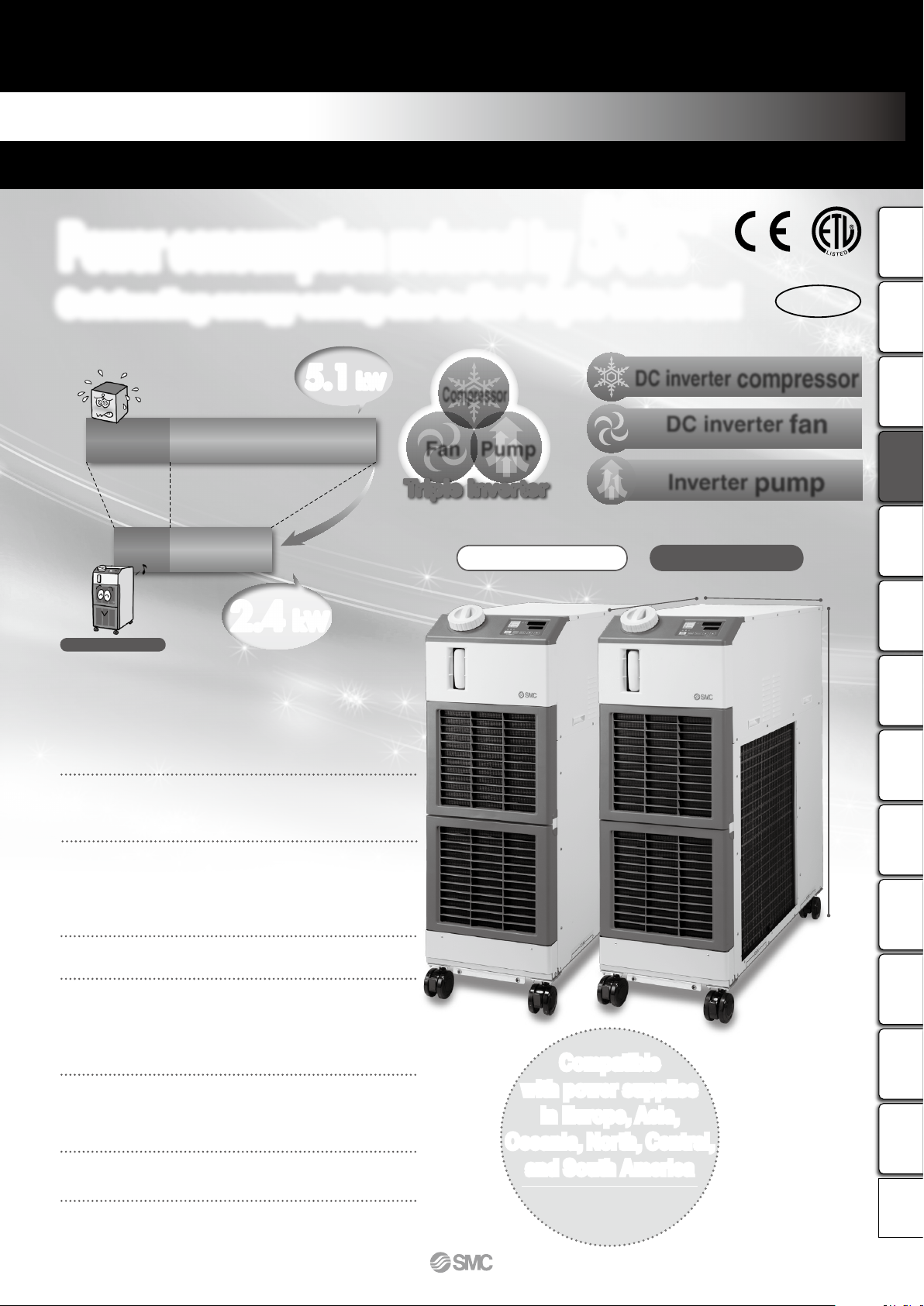
Power consumption reduced by 53
%
*
1
Outstanding energy saving due to the triple inverter!
Non-inverter chiller
*
1 Under the conditions shown on page 131
HRSH090
Triple inverter
Cooling capacity
9.5
kW
W 377 x H 1080 x D 970 mm
Compact, Space saving
Indoor use
Low-noise
design
45
°C
Temperature
stability
66 dB
Operating noise
Max.
Set temperature
range
5°C to 40°C
Max. ambient
temperature
5.1 kW
2.4 kW
(UL Standard)
RoHS
(Only 400 VAC type)
±0.1°C
(When a load is stable)
HRSH090 Series
Inverter Type
Circulating Fluid Temperature Controller
Thermo-chiller
130
HRSHRS090
HRS100/150
HRSH090
HRSHHRSEHRZHRZDHRWHECRHECHED HEB
Technical
Data
Page 2
compressor
fan pump
DC inverter
DC inverter Inverter
(For the air-cooled type)
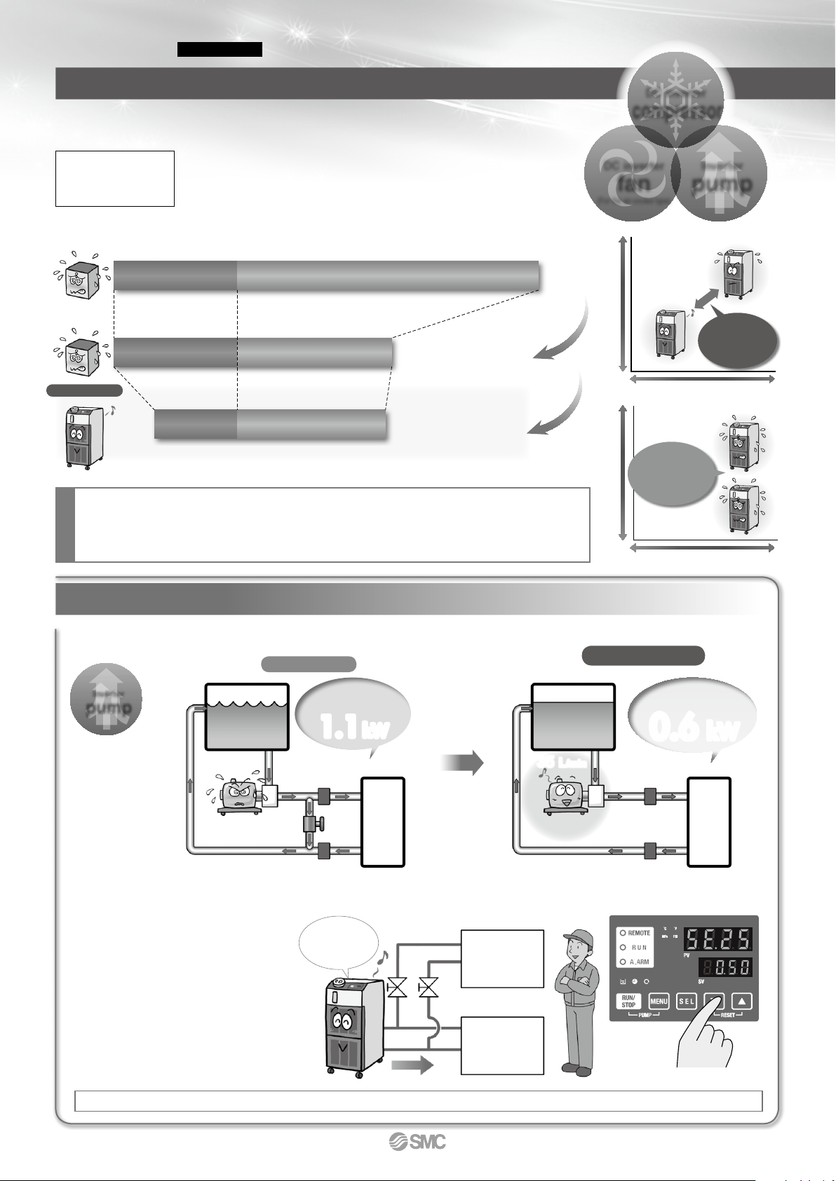
Circulating fluid pressure adjustable
Power reducing effect of the inverter pump
Inverter pump
pump
Inverter
Tank
Inverter pumpNon-inverter pump
55 L/min
55 L/min
35 L/min
35 L/min
20 L/min
35 L/min 0.3 MPa35 L/min 0.3 MPa
Tank
Triple inverter
User’s
equipment
User’s
equipment
Discharge pressure of the
circulating fluid can be set with the
operation panel. The inverter pump
automatically controls the
discharge pressure to the set
pressure without adjusting the bypass piping under various piping
conditions. Power consumption
can be reduced by this control.
(Operation to the set pump operating frequency is also possible.)
When the product is used with the flow path switched for maintenance, the pressure adjusting function controls the discharge pressure to be stable. (Secure the specified minimum flow for each branch circuit.)
The motor rotation
rat e is contr oll ed
to a suitable level,
for the neces sary
pr es su re , by the
inverter pump.
The pump is operat ed at
the rate d out pu t all the
ti me. W ith t he ex cess
pow er consu mptio n, the
circuit needs to bypass 20
L/min.
Operating ratio: Ratio of 9.5 kW (with heat load) to 0 kW (without heat load) Operating ratio: 50%, with heat load of 9.5 kW all the time
Non-inverter
Pump/1.1 kW
Compressor + Fan + Others/
4 kW
Power
consumption
5.1 kW
Non-inverter
Pump/1.1 kW
Compressor + Fan + Others/2.0 kW
Non-inverter Inverter
Reduced by 39%
with compressor and fan inverters
Power consumption
3.1 kW
Pump/ 0.6 kW
Compressor + Fan + Others/1.8 kW
Inverter Inverter
Reduced by 53%
with the additional pump inverter
Power consumption
2.4 kW
HRSH090
Inverter pump
Current model
The inverter respectively controls the number of motor rotations of the compressor, fan and pump depending on the load from the user’s equipment.
With the inverter, it is possible to operate with the same performance even with the power supply of 50 Hz.
compared with a non-inverter
Power
consumption
reduced by 53%
Common conditions for non-inverter and triple inverter:
¡Ambient temperature: 32°C ¡Circulating fluid temperature: 20°C
¡Circulating fluid flow rate: 35 L/min at 0.3 MPa (60 Hz) ¡Heat load: 9.5 kW
Conditions for non-inverter chiller: Continuous operation of the compressor which can cool down 9.5 kW at
60 Hz. The pump shall be same as that of the HRSH.
Conditions
1.1kW
Power consumption
(Pump only)
Automatically
controls the
discharge pressure
to be stable.
User’s
equipment
A
User’s
equipment
B
Operation
display panel
(Circulating fluid discharge
pressure setup screen)
0.6 kW
Power consumption
(Pump only)
131
Thermo-chiller
Inverter Type
HRSH090 Series
Circulating Fluid Temperature Controller
Non-inverter
chiller
Double inverter
chiller
HRSH090
Triple inverter
The number of
motor rotations is
controlled depending
on the load.
Built-in triple inverter
HighLoadLow
Low HighMotor rotation rate
Non-inverter
Keeps high
frequency rotation
all the time,
and wastes power.
HighLoadLow
Low HighMotor rotation rate
Page 3
Model
Cooling
method
Cooling
capacity
Power supply
Option
Page 148
Optional
accessories
International
standards
Air-cooled
refrigeration
9.5 kW
· 3-phase 200 VAC (50 Hz),
3-phase 200 to 230 VAC (60 Hz)
·
3-phase 380 to 415 VAC (50/60 Hz)
· With earth
leakage breaker
(For 400 V type as
standard)
· With automatic
fluid fill function
· Applicable to
deionized water
piping
· Piping conversion
fitting
· Bypass piping set
· Electric conductivity
control set
· Particle filter set
· Filter for circulating
fluid fill port
·
Drain pan set (With
water leakage sensor)
·
Wired remote controller
(400 V as standard)
(Only 200 V as an option)
Water-cooled
refrigeration
11.0 kW
Pages 149 to 152
Variations
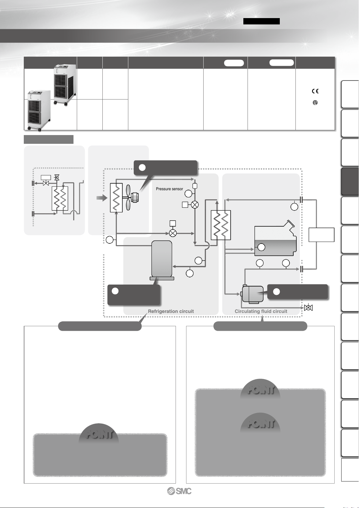
Circuit diagram
Circulating fluid circuitRefrigeration circuit
Facility water circuit
WPR
Water-regulating valve
Facility water outletFacility water inlet
Air release valve for
facility water discharge
Water-cooled
condenser
¡
The DC inverter compressor compresses the refrigerant gas, and
discharges the high temperature and high pressure refrigerant gas.
¡In the case of air-cooled refrigeration, the high temperature and
high pressure refrigerant gas is cooled down by an air-cooled
condenser with the ventilation of the DC inverter fan, and becomes a liquid. In the case of water-cooled refrigeration, the refrigerant gas is cooled by a water-cooled condenser with the facility water in the facility water circuit, and becomes a liquid.
¡
The liquefied high pressure refrigerant gas expands and its temperature lowers when it passes through expansion valve A and vaporizes by taking heat from the circulating fluid in the evaporator.
¡The vaporized refrigerant gas is sucked into the DC inverter com-
pressor and compressed again.
¡When heating the circulating fluid, the high pressure and high
temperature refrigerant gas is bypassed into the evaporator by
expansion valve B, to heat the circulating fluid.
¡ The circulating fluid discharged from the inverter pump, is heat-
ed or cooled by the user’s equipment and returns to the tank.
¡The circulating fluid is sent to the evaporator by the inverter
pump, and is controlled to a set temperature by the refrigeration
circuit, to be discharged to the user’s equipment side again by
the thermo-chiller.
POINT
POINT
POINT
Adjusting the discharge pressure by pump inverter
control eliminates wasteful discharge of the circulating fluid and realizes energy saving operation.
Since the refrigeration circuit is controlled by the
signal from 2 temperature sensors (for return and
discharge), precise temperature control of the circulating fluid can be performed. Therefore, there is no
necessity of absorbing the temperature difference in
the circulating fluid with a large tank capacity, and
realizes high temperature stability even with a smallsize tank. Also, contributes to space-saving.
The combination of inverter control of the compressor and fan (facility water flow control by a water-regulating valve is used in water-cooled refrigeration),
and the precise control of expansion valves A and B
realizes energy saving operation without waste and
high temperature stability.
132
Thermo-chiller
Inverter Type
HRSH090 Series
Circulating Fluid Temperature Controller
Expansion valve A
Pressure sensor
(For high-pressure
refrigerant gas)
Pressure sensor
(For low-pressure
refrigerant gas)
Level
switch
Circulating
fluid return port
Temperature sensor
(For discharge)
Temperature sensor
(For compressor intake)
Pressure sensor
(For discharge)
Temperature sensor
(For return)
Drain port
Circulating
fluid outlet
Dryer
Temperature sensor
(For compressor discharge)
Heat exchanger
Resin tank
Fluid
level
indicator
User's equipment
(Heat source)
Expansion valve B
E
TS
PS TS
TS
E
PS
PS
TS
DC inverter
compressor
DC inverter fan
Inverter pump
Ventilation
Air-cooled
condenser
D
2
1
3
* This circuit construction of the position of the
parts may be different from actual product.
HRSH090-W-m
(Water-cooled refrigeration)
HRSH090-A-m
(Air-cooled refrigeration)
Circulating fluid circuitRefrigeration circuit
HRSHRS090
HRS100/150
HRSH090
HRSHHRSEHRZHRZDHRWHECRHECHED HEB
Technical
Data
Page 4
0
5
10
15
20
25
30
35
40
45
0 10 20 30 40 50
Time [Minute]
Circulating fluid temperature
[
°
C
]
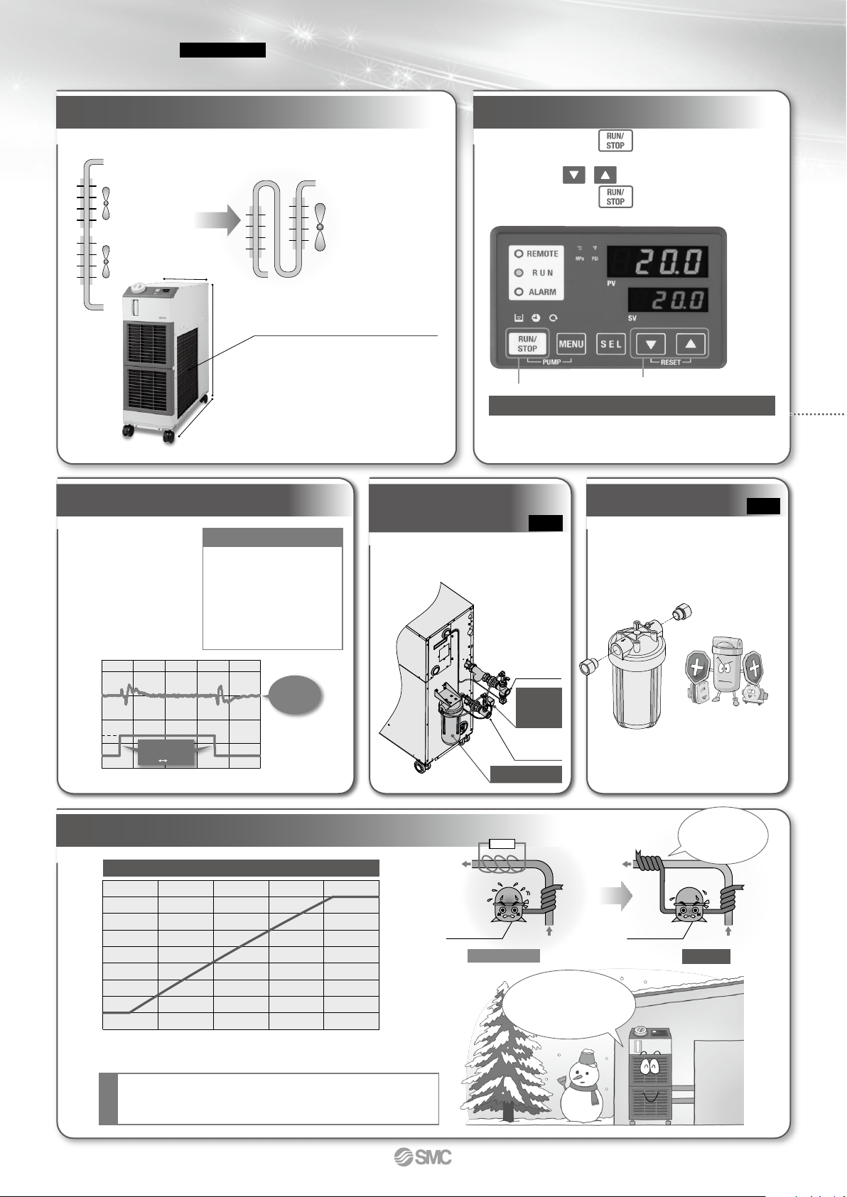
Temperature increase with the heating function
Large digital display
Circulating fluid
Compressor
Heater
wqe
Heating functions are
required to maintain a constant
temperature particularly
in the winter when the ambient
temperature is low.
HRSH
Circulating fluid
Compressor
Hot discharged gas
from refrigerant
Heating method
using discharged
heat makes a heater
unnecessary.
Compact and lightweight
130
kg
Circulating fluid can be heated without a heater.
Simple operation
Step q Press the key.
Step w Adjust the temperature setting with
the / keys.
Step e Press the key to stop.
Easy operation by these steps
The “large digital display” (7-segment and 4 digits) and
“2 row display” provide a clearer view of the current
value (PV) and set value (SV).
Cool fluid
from
refrigerant
Cool fluid
from
refrigerant
∗ This is just an example diagram.
Current model
User’s
equipment
Reduced-height double condenser structure
[mm]
1080
970
377
21
20
19
0 10 20 30 40 50
Time [Minute]
9.5 kW
load
0 kW
load
Heat load
fluctuation
(0 kW
9.5 kW)
When a load
is stable
±0.1°C
Circulating fluid
temperature
[
°
C
]
Current
Multiple air-cooled
condensers are
arranged one
above the other.
Achieved a maximum
reduction in the height
of the product while
expanding the cooling
capacity, by providing
overlapped air-cooled
condensers.
Compact tank 18 L
Temperature followability
control reduced the tank
capacity required as a buffer.
Aluminum air-cooled
condenser
High heat transfer efficiency,
Lightweight
¡Ambient temperature: 5°C
¡Power supply: 200 V, 60 Hz
¡Circulating fluid flow: 45 L/min at 0.5 MPa
¡External piping: Bypass piping
Conditions
* For HRSH090-A-20
By controlling the DC inverter compressor, DC
inverter fan, and electronic expansion valve
simultaneously, it maintains the good temperature stability when the
heat load fluctuates.
(With DI filter + Solenoid valve kit for control)
¡Outdoor air temperature: 32°C
¡Circulating fluid temperature setting: 20°C
¡Heat load in the user’s equipment: 9.5 kW
¡Power supply: 200 V, 60 Hz
¡Circulating fluid flow: 45 L/min at 0.5 MPa
¡External piping: Bypass piping + Heat load
Conditions
Temperature stability ±0.1°C (When a load is stable)
Electric conductivity control set
Particle filter set
The electric conductivity of the circulating fluid
can be set with the controller monitor arbitrarily.
Circulating fluid
return port
Set control range:
5.0 to
45.0 mS/cm
Solenoid
valve for
control
Circulating
fluid outlet
DI filter
* For HRSH090-A-20
133
Thermo-chiller
Inverter Type
HRSH090 Series
Circulating Fluid Temperature Controller
Effective to prevent foreign matter from
entering the user’s equipment and chiller.
Removes foreign matter
in the circulating fluid.
· Prevents pump malfunction.
· Prevents lowering of the watercooled condenser performance.
p. 150
p. 150
Protects the pump and
condenser from foreign matter!!
Page 5
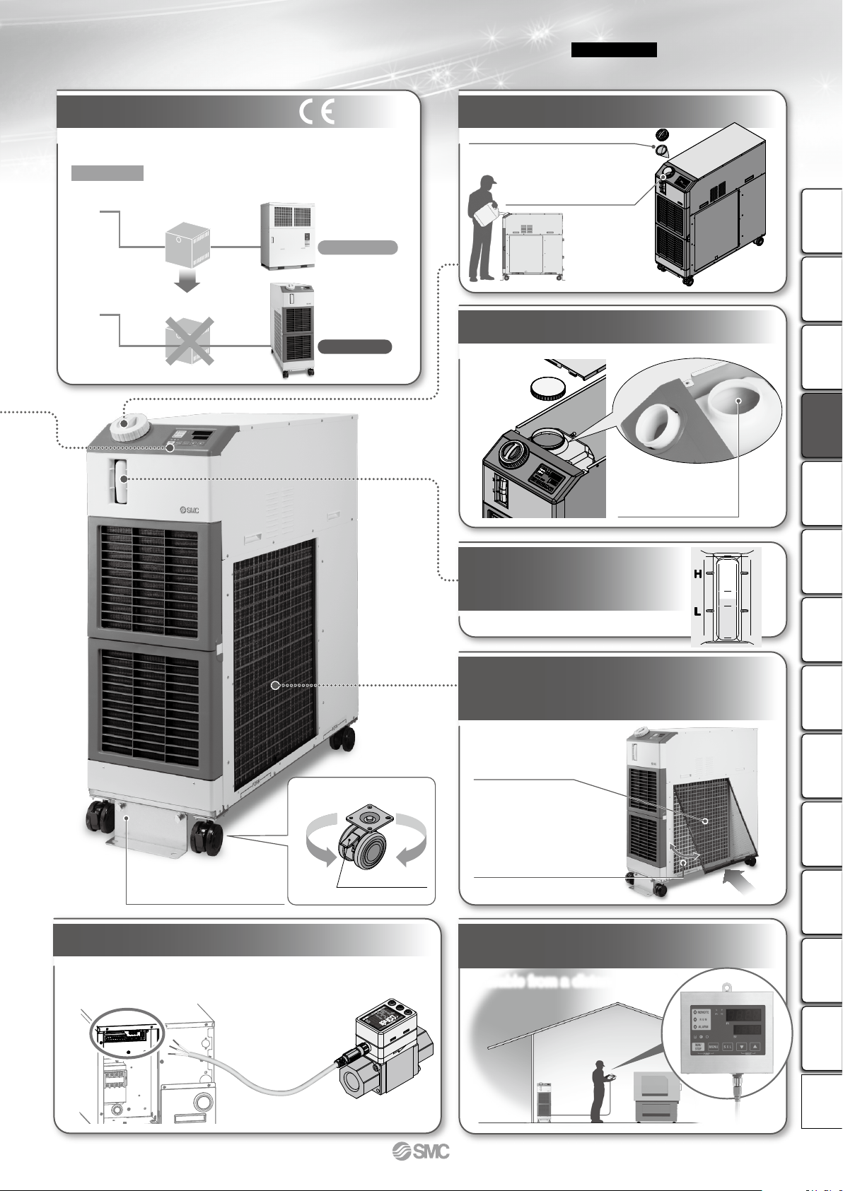
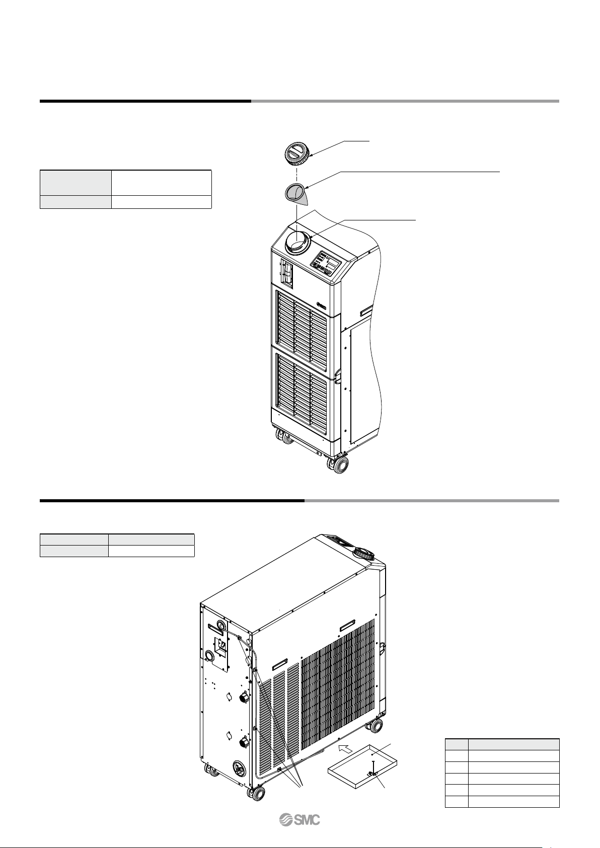
An opening with a cap is included
separately from the water inlet.
Opening diameter: ø110
Ventilation
Globally compatible power supplies
Shaped for easy supply of circulating fluid
Easy cleaning of the tank
Easy check of the
circulating fluid level
Tool-less inspection and
cleaning of air-cooled condenser
∗ For air-cooled refrigeration
The angled supply port facilitates
the supply of circulating fluid.
∗ It can be removed
with no tools.
Dustproof
filter
Easy to clean dust and
cutting chips, etc. stuck
to the dustproof net
with a brush or air blow.
∗
Remove bracket when moving,
using casters.
Anchor bolt fixing bracket
RotationRotation
With unfixed caster
Locking lever
(front wheels only)
Power can be supplied from the terminal block
on the rear side to external switches, etc.
Operable from a distance.
Flow switch
Power supply (24 VDC) available
Wired remote controller
(Optional accessory on page 152)
Refer to the Best
Pneumatics No. 8
for details.
Filter for circulating fluid fill port (Optional accessory on page 151)
∗
After supplying the circulating fluid, the tank
lid can be closed with the filter mounted.
(Europe, Asia, Oceania, Central and South America)
Step-down transformer
Unnecessary
380 to 415 VAC
Transformer unnecessary
Step-down transformer
380 VAC 200 VAC
Power supply
Transformers are unnecessary even when used overseas.
Applicable to 200 to 230 VAC, or 380 to 415 VAC
Current model
HRSH090
134
Thermo-chiller
Inverter Type
HRSH090 Series
Circulating Fluid Temperature Controller
(400 V type only)
HRSHRS090
HRS100/150
HRSH090
HRSHHRSEHRZHRZDHRWHECRHECHED HEB
Technical
Data
Page 6
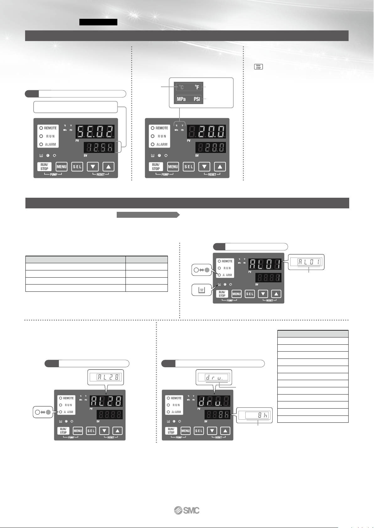
PV
SV
Flashing
Flashing
Lights up
Alarm code
Accumulated
time
Displayed item
PV PV
Convenient functions (Refer to the Operation Manual for details.)
Ex.
SE.02
“ON timer”
Unit conversion function
Temperature and pressure units can be
changed.
Timer operation function
Timer for ON and OFF can be set in
units of 0.5 h up to 99.5 h.
Ex.) Can set to stop on Saturday and Sunday
and restart on Monday morning.
Timer
The time remaining can be checked.
Power failure auto-restart function
Automatic restart from stoppage due to power failure, etc. is possible without pressing the
key and remote operation.
Anti-freezing operation function
If the temperature approaches freezing point,
e.g. in winter at night, the pump operates automatically and the heat generated by the
pump warms the circulating fluid, preventing
freezing.
Key-lock function
Can be set in advance to protect the set values from being changed by pressing keys by
mistake.
Function to output a signal for
completion of preparation
Notifies by communication when the temperature reaches the pre-set temperature range.
Independent operation of the pump
The pump can be operated independently
while chiller is powered off. You can check
piping leak and remove the air.
Orange
indicator
lights up.
Temperature unit
Pressure unit
For details, refer to page 146.
Self diagnosis and check display
Display of individual alarm codes
Operation is monitored all the time by the integrated sensor.
Should any error occur, the self diagnosis result is displayed by the applicable alarm code.
This makes it easier to identify the cause of the alarm.
Can be used before requesting service.
Changeable alarm set values
Setting item Set value
Circulating fluid discharge temperature rise
Circulating fluid discharge temperature drop
Circulating fluid discharge pressure rise
Circulating fluid discharge pressure drop
5 to 55°C
1 to 39°C
0.05 to 0.6 MPa
0.05 to 0.6 MPa
Ex.
AL01 “Low level in tank”
Alarm codes notify of checking times.
Notifies when to check the pump and fan motor.
Helpful for facility maintenance.
Ex.
AL28 “Pump maintenance”
Check display
The internal temperature, pressure and
operating time of the product are displayed.
Ex.
drv. “Accumulated operating time”
Displayed item
Circulating fluid outlet temperature
Circulating fluid return temperature
Circulating fluid flow rate
∗1
Compressor gas temperature
Circulating fluid outlet pressure
Compressor gas discharge pressure
Compressor gas return pressure
Accumulated operating time
Accumulated operating time of pump
Accumulated operating time of fan
∗2
Accumulated operating time of compressor
Accumulated operation time of dustproof filter
∗2
∗1 This is not measurement value.
Use it for reference.
∗2 These are displayed only for
air-cooled refrigeration.
∗ The fan motor is not used in water-cooled refrigeration.
135
Thermo-chiller
Inverter Type
HRSH090 Series
Circulating Fluid Temperature Controller
Page 7
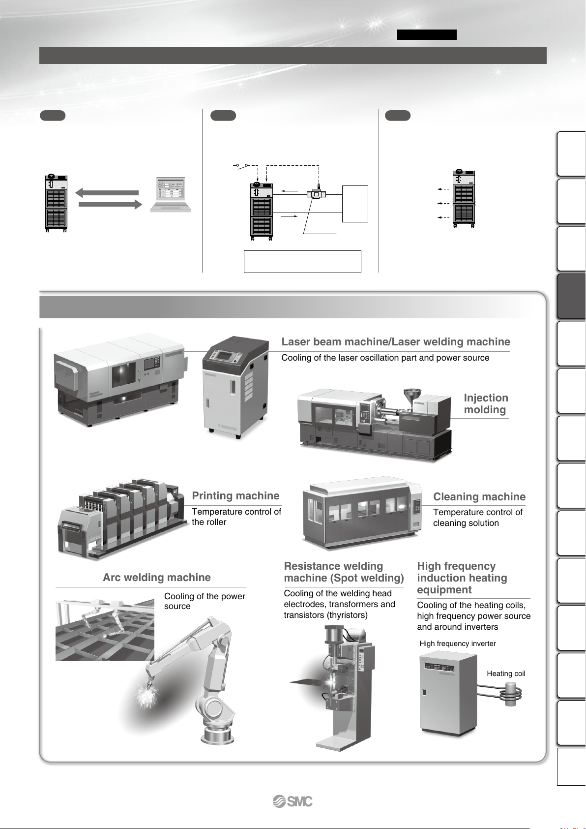
Laser beam machine/Laser welding machine
Cooling of the laser oscillation part and power source
Printing machine
Temperature control of
the roller
Cleaning machine
Temperature control of
cleaning solution
Injection
molding
Arc welding machine
Cooling of the power
source
High frequency
induction heating
equipment
Cooling of the heating coils,
high frequency power source
and around inverters
High frequency inverter
Heating coil
Resistance welding
machine (Spot welding)
Cooling of the welding head
electrodes, transformers and
transistors (thyristors)
PC
HRSH
Output 1
Output 2
Output 3
HRSH
· Output setting example
Output 1: Temperature rise
Output 2: Pressure rise
Output 3: Operation status (start, stop, etc.)
Power for flow switch (24 VDC) can
be supplied from thermo-chiller.
The alarm and status generated in the product
are assigned to 3 output signals based on their
contents, and can be output.
Ex. 1 Ex. 2 Ex. 3
Remote signal I/O through
serial communication
The remote operation is enabled (to start and
stop) through serial communication.
One of the contact inputs is used for remote operation and the other is used for a flow switch to monitor the flow, and their warning outputs are taken in.
Alarm and operation status
(start, stop, etc.) signal output
Remote operation signal input
¡Circulating fluid
temperature setting
¡Start and stop
¡Circulating fluid discharge
temperature
¡Circulating fluid discharge pressure
¡Run and stop status
¡Alarm information
¡Various setting information
¡Preparation completion status
Remote
operation
switch
Input 2Input 1
To the user’s
equipment
HRSH
Communication function
The serial communication (RS232C/RS485) and contact I/Os (2 inputs and 3 outputs) are equipped as standard.
Communication with the user’s equipment and system construction are possible, depending on the application.
A 24 VDC output can be also provided, and is available for a flow switch (SMC’s PF2W, etc.).
Flow switch
Low flow switch flow signal
Applications
136
Thermo-chiller
Inverter Type
HRSH090 Series
Circulating Fluid Temperature Controller
HRSHRS090
HRS100/150
HRSH090
HRSHHRSEHRZHRZDHRWHECRHECHED HEB
Technical
Data
Page 8
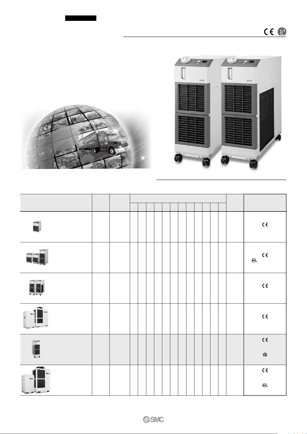
Global Supply Network
SMC has a comprehensive network in the global market.
We now have a presence of more than 500 branch offices and distributors
in 83 countries world wide such as Asia, Oceania, North/Central/South
America, and Europe. With this global network, we are able to provide a
global supply of our substantial range of products with the best service.
We also provide full support to local factories, foreign manufacturing
companies and Japanese companies in each country.
Series
Temperature
stability
[°C]
Set temperature
range
[°C]
Cooling capacity [kW]
Environment
International
standards
1.2 1.8 2.4 3 5 6 9 10 15 20 25 28
HRSE
Basic type
±2.0
10 to 30
VVV
Indoor
use
(Only 230 VAC type)
HRS
Standard type
±0.1
5 to 40
VVVVVV
Indoor
use
(Only 60 Hz)
HRS090
Standard type
±0.5
5 to 35
V
Indoor
use
(400 V as standard)
HRS100/150
Standard type
±1.0
5 to 35
VV
Outdoor
installation
IPX4
(400 V as standard)
HRSH090
Inverter type
±0.1
5 to 40
V
Indoor
use
(400 V as standard,
200 V as an option)
(Only 200 V as an option)
HRSH
Inverter type
±0.1
5 to 35
VVVVV
Outdoor
installation
IPX4
(400 V as standard,
200 V as an option)
(Only 200 V as an option)
Lots of variations are available in response to the users’ requirements.
SMC Thermo-chiller Variations
137
Thermo-chiller
Inverter Type
HRSH090 Series
Circulating Fluid Temperature Controller
Page 9
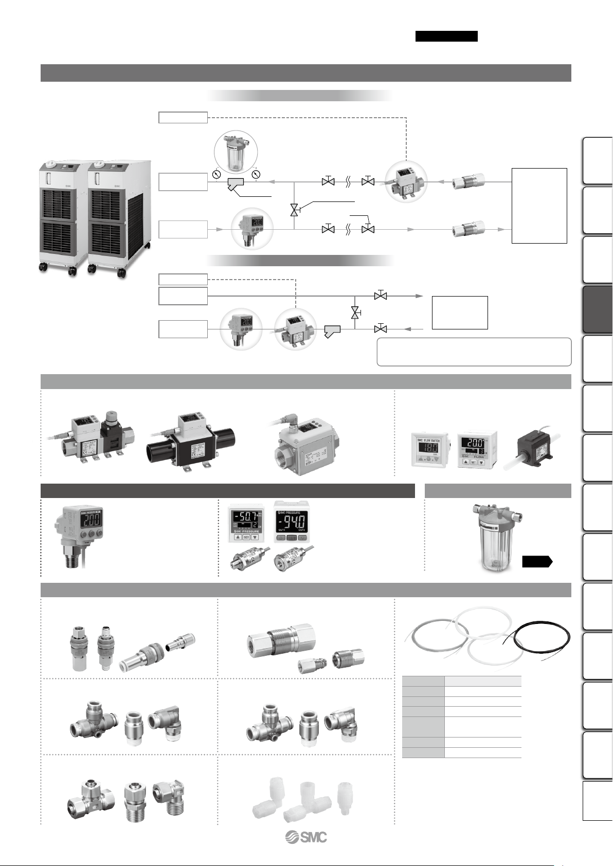
Particle Filter
Pressure Switch: Monitors pressure of the circulating fluid.
2-Color Display
High-Precision
Digital Pressure Switch
ISE80
Pressure Sensor for
General Fluids
PSE56
Pressure Sensor
Controller
PSE200,300
Refer to the Best Pneumatics No. 8 for details.
3-Color Display Digital Flow Switch for Water
PF3W
3-Color Display
Electromagnetic Type Digital Flow Switch
LFE
Digital Flow Switch for
Deionized Water and Chemical Liquids
PF2D
4-Channel Flow Monitor
PF2200
Flow Switch: Monitors flow rate and temperature of the circulating fluid.
Refer to the Best Pneumatics No. 8 for details.
Integrated flow adjustment valve
and temperature sensor
Manage pressure and flow rate: digital display
makes these aspects
“visible”
PVC Piping
S Coupler
KK
Series
T
TU
TH
TD
TL
TLM
Material
Nylon
Polyurethane
FEP (Fluoropolymer)
Modified PTFE
(Soft fluoropolymer)
Super PFA
PFA
Tubing
T
Stainless Steel 316
One-touch Fittings
KQG2
Stainless Steel 316 Insert Fittings
KFG2
Fluoropolymer Fittings
LQ
S Coupler/Stainless Steel
(Stainless Steel 304)
KKA
Metal One-touch Fittings
KQB2
Fittings and Tubing
Refer to the Best Pneumatics No. 7 for details.
Circulating
fluid outlet
Y-strainer
User’s
equipment
User’s
equipment
Pressure Switch
Flow Switch
Flow Switch
Valve
Circulating fluid
return port
Facility water
outlet
Facility water
inlet
Facility Water Line (Water-cooled)
Circulating Fluid Line
Pressure Switch
Particle Filter
Fittings and Tubing
Terminal block
Power supply (24 VDC) available
Terminal block
Power supply (24 VDC) available
Bypass valve
p. 150
Circulating Fluid/Facility Water Line Equipment
138
Thermo-chiller
Inverter Type
HRSH090 Series
Circulating Fluid Temperature Controller
HRSHRS090
HRS100/150
HRSH090
HRSHHRSEHRZHRZDHRWHECRHECHED HEB
Technical
Data
A
Page 10

CONTENTS
HRSHRS090
HRS100/150
HRSH090
HRSHHRSEHRZHRZDHRWHECRHECHED HEB
Technical
Data
HRSH090 Series
Inverter Type
Thermo-chiller HRSH090 Series
How to Order/Specifications
..........................
Air-cooled 200 V/400 V
..........................
Water-cooled 200 V/400 V
Cooling Capacity
Pump Capacity
Dimensions
Recommended External Piping Flow
Cable Specifications
Operation Display Panel
List of Function
................................................................
Alarm
Communication Functions
Options
With Earth Leakage Breaker
With Automatic Fluid Fill Function
Applicable to Deionized Water Piping
Conforming to CE/UL Standards
...............................................
.................................................
.......................................................
................
.........................................
...................................
.................................................
................................
.............................
....................
...............
......................
Page 141
Page 142
Page 143
Page 143
Page 144
Page 145
Page 145
Page 146
Page 146
Page 146
Page 147
Page 148
Page 148
Page 148
Page 148
Optional Accessories
q Piping Conversion Fitting
w Bypass Piping Set
e Electric Conductivity Control Set
r Particle Filter Set
t Filter for Circulating Fluid Fill Port
Drain Pan Set (With Water Leakage Sensor)
y
u Wired Remote Controller
..........................................
..............................
........................................
..................
................
.............................
Cooling Capacity Calculation
Required Cooling Capacity Calculation
Precautions on Cooling Capacity Calculation
Circulating Fluid Typical Physical Property Values
Specific Product Precautions
.................................
............
......
...
...
Page 149
Page 149
Page 150
Page 150
Page 151
Page 151
Page 152
Page 153
Page 154
Page 154
Page 155
140
Page 11

Thermo-chiller
141
Inverter Type
Air-cooled 200 V/400 V Type
HRSH090 Series
How to Order
(400 V type only)
(Option S only)
(UL Standards)
(Option S only)
RoHS
HRSH
090
Cooling capacity
9.5 kW
090
Cooling method
A
Air-cooled refrigeration
Pipe thread type
Rc
Nil
G (with Rc-G conversion fitting)
F
NPT (with Rc-NPT conversion fitting)
N
3-phase 200 VAC (50 Hz)
20
3-phase 200 to 230 VAC (60 Hz)
3-phase 380 to 415 VAC (50/60 Hz)
40
A
Power supply
20
Option
None
Nil
1
*
With earth leakage breaker
B
With automatic fluid fill function
J
Applicable to deionized water piping
M
2
*
Conforming to CE/UL standards
S
SI unit only
W
¡When multiple options are combined, indicate symbols in
alphabetical order.
*1 200 V type only.
400 V type is provided with an earth leakage breaker as standard.
*2 200 V type only. 400 V type is CE-compliant as standard.
Additionally, combination with option B is not necessary.
An earth leakage breaker is equipped as standard.
Specifications
Cooling method Air-cooled refrigeration
Refrigerant R410A (HFC) (GWP1975)
Refrigerant charge kg 1.32
Control method PID control
Ambient temperature/Humidity/Altitude
Circulating fluid
Set temperature range
Cooling capacity
Heating capacity
Temperature stability
Pump
capacity
Settable pressure range
Minimum operating flow rate
Tank capacity L 18
Circulating fluid outlet, circulating fluid return port
Circulating fluid system
Tank drain port Rc1/4 (Symbol F: G1/4, Symbol N: NPT1/4)
Fluid contact material
Power supply
Applicable earth
leakage breaker
Rated operating current
Electrical system
Rated power consumption
Noise level (Front 1 m/Height 1 m)
Accessories
Weight (dry state) kg Approx. 130
*1 Use a 15% ethylene glycol aqueous solution if operating in a place where the ambient temperature and/or circulating fluid temperature is 10°C or less.
*2 Use fluid in condition below as the circulating fluid.
Tap water: Standard of The Japan Refrigeration And Air Conditioning Industry Association (JRA GL-02-1994)
15% ethylene glycol aqueous solution: diluted by tap water in condition above without any additives such as antiseptics.
Deionized water: Electric conductivity 1 μS/cm or higher (Electric resistivity 1 MΩ·cm or lower)
*3 q Ambient temperature: 32°C, w Circulating fluid: Tap water, e Circulating fluid temperature: 20°C, r Circulating fluid flow rate: Rated flow, t Power supply: 200/400 VAC
*4 q Ambient temperature: 32°C, w Circulating fluid: Tap water, e Circulating fluid flow rate: Rated flow, r Power supply: 200/400 VAC
*5 q Ambient temperature: 32°C, w Circulating fluid: Tap water, e Circulating fluid temperature: 20°C, r Load: Same as the cooling capacity,
t Circulating fluid flow rate: Rated flow, y Power supply: 200/400 VAC, u Piping length: Shortest
*6 With the pressure control mode by inverter. When the pressure control mode is not used, the pump power frequency set mode can be used.
*7 Fluid flow rate to maintain the cooling capacity. If the actual flow rate is lower than this, install a bypass piping.
*8 To be prepared by user. A specified earth leakage breaker is installed for option B [With earth leakage breaker], option S [Conforming to CE/UL standards] and 400 V type.
*9 If the product is used at altitude of 1000 m or higher, refer to “Operating Environment/Storage Environment” (page 155) Item 14 “* For altitude of 1000 m or higher.”
*10 The anchor bolt fixing brackets (including 4 M10 bolts) are used for fixing to wooden skids when packaging the thermo-chiller. No anchor bolt is included.
B
Model
1, 9
*
2
*
1
*
3, 9
*
4
*
5
Rated flow (Outlet) L/min 45 (0.5 MPa)
Maximum flow rate L/min 60
Maximum pump head m 50
*
8
*
Rated current
Sensitivity of leak current
6
*
5
*
5
*
°C/% Temperature: 5 to 45°C, Humidity: 30 to 70%, Altitude: less than 3000 m
°C 5 to 40
kW 9.5
kW 2.5
°C
MPa 0.1 to 0.5
7
*
L/min 20
3-phase 200 VAC (50 Hz), 3-phase 200 to 230 VAC (60 Hz)
A 30 20
mA 30
A 15 8
kW (kVA) 4.6 (5.2) 5.0 (5.6)
5
*
dB (A) 66
Y-strainer (40 meshes) 25A, Barrel nipple 25A, Anchor bolt fixing brackets 2 pcs. (including 4 M10 bolts)
HRSH090-Al-20-l HRSH090-Al-40-l
Tap water, 15% Ethylene glycol aqueous solution, Deionized water
±0.1
Rc1 (Symbol F: G1, Symbol N: NPT1)
Stainless steel, Copper (Heat exchanger brazing), Brass, Bronze, Carbon, Ceramic,
Allowable voltage range ±10%
(No continuous voltage fluctuation)
Operation Manual (for installation/operation) 2 pcs. (English 1 pc./Japanese 1 pc.),
PE, PVC, POM, PTFE, NBR, EPDM, FKM, PP
3-phase 380 to 415 VAC (50/60 Hz)
Allowable voltage range ±10%
(No continuous voltage fluctuation)
Alarm code list stickers 2 pcs. (English 1 pc./Japanese 1 pc.),
10
*
Page 12

142
HRSHRS090
HRS100/150
HRSH090
HRSHHRSEHRZHRZDHRWHECRHECHED HEB
Technical
Data
Thermo-chiller
Inverter Type
Water-cooled 200 V/400 V Type
HRSH090 Series
How to Order
(400 V type only)
(Option S only)
(UL Standards)
(Option S only)
RoHS
Cooling capacity
090
11.0 kW
HRSH
090
Cooling method
W
Water-cooled refrigeration
Pipe thread type
Rc
Nil
G (with Rc-G conversion fitting)
F
NPT (with Rc-NPT conversion fitting)
N
3-phase 200 VAC (50 Hz)
20
3-phase 200 to 230 VAC (60 Hz)
3-phase 380 to 415 VAC (50/60 Hz)
40
W
Power supply
20
Option
None
Nil
1
*
With earth leakage breaker
B
With automatic fluid fill function
J
Applicable to deionized water piping
M
2
*
Conforming to CE/UL standards
S
SI unit only
W
¡When multiple options are combined, indicate symbols
in alphabetical order.
*1 200 V type only.
400 V type is provided with an earth leakage breaker as standard.
*2 200 V type only. 400 V type is CE-compliant as standard. Additionally,
combination with option B is not necessary. An earth leakage breaker is
equipped as standard.
Specifications
Cooling method Water-cooled refrigeration
Refrigerant R410A (HFC) (GWP1975)
Refrigerant charge kg 1.4
Control method PID control
Ambient temperature/Humidity/Altitude
Circulating fluid
Set temperature range
Cooling capacity
Heating capacity
Temperature stability
Pump
capacity
Settable pressure range
Minimum operating flow rate
Tank capacity L 18
Circulating fluid outlet, circulating fluid return port
Circulating fluid system
Tank drain port Rc1/4 (Symbol F: G1/4, Symbol N: NPT1/4)
Fluid contact material
Temperature range °C 5 to 40
Pressure range MPa 0.3 to 0.5
Required flow L/min 25
Facility water pressure differential
Facility water inlet/outlet Rc1/2
Fluid contact material
Facility water system
Power supply
Applicable earth
leakage breaker
Rated operating current
Rated power consumption
Electrical system
Noise level (Front 1 m/Height 1 m)
Accessories
Weight (dry state) kg Approx. 121
*1 Use a 15% ethylene glycol aqueous solution if operating in a place where the ambient temperature and/or circulating fluid temperature is 10°C or less.
*2 Use fluid in condition below as the circulating fluid.
Tap water: Standard of The Japan Refrigeration And Air Conditioning Industry Association (JRA GL-02-1994)
15% ethylene glycol aqueous solution: diluted by tap water in condition above without any additives such as antiseptics.
Deionized water: Electric conductivity 1 μS/cm or higher (Electric resistivity 1 MΩ·cm or lower)
*3 q Ambient temperature: 32°C, w Circulating fluid: Tap water, e Circulating fluid temperature: 20°C, r Circulating fluid flow rate: Rated flow, t Power supply: 200/400 VAC
*4 q Ambient temperature: 32°C, w Circulating fluid: Tap water, e Circulating fluid flow rate: Rated flow, r Power supply: 200/400 VAC
*5 q Ambient temperature: 32°C, w Circulating fluid: Tap water, e Circulating fluid temperature: 20°C, r Load: Same as the cooling capacity,
t Circulating fluid flow rate: Rated flow, y Power supply: 200/400 VAC, u Piping length: Shortest
*6 With the pressure control mode by inverter. When the pressure control mode is not used, the pump power frequency set mode can be used.
*7 Fluid flow rate to maintain the cooling capacity. If the actual flow rate is lower than this, install a bypass piping.
*8 To be prepared by user. A specified earth leakage breaker is installed for option B [With earth leakage breaker], option S [Conforming to CE/UL standards] and 400 V type.
*9 The anchor bolt fixing brackets (including 4 M10 bolts) are used for fixing to wooden skids when packaging the thermo-chiller. No anchor bolt is included.
Model
1
*
2
*
1
*
3
*
4
*
5
Rated flow (Outlet) L/min 45 (0.5 MPa)
Maximum flow rate L/min 60
Maximum pump head m 50
*
8
*
Rated current
Sensitivity of leak current
6
*
5
*
5
*
°C/% Temperature: 5 to 45°C, Humidity: 30 to 70%, Altitude: less than 3000 m
°C 5 to 40
kW 11.0
kW 2.5
°C
MPa 0.1 to 0.5
7
*
L/min 20
MPa 0.3 or more
3-phase 200 VAC (50 Hz), 3-phase 200 to 230 VAC (60 Hz)
A 30 20
mA 30
A 12 6.8
kW (kVA) 3.8 (4.0) 4.0 (4.7)
5
*
dB (A) 65
Y-strainer (40 meshes) 25A, Barrel nipple 25A, Anchor bolt fixing brackets 2 pcs. (including 4 M10 bolts)
HRSH090-Wl-20-l HRSH090-Wl-40-l
Tap water, 15% Ethylene glycol aqueous solution, Deionized water
±0.1
Rc1 (Symbol F: G1, Symbol N: NPT1)
Stainless steel, Copper (Heat exchanger brazing), Brass, Bronze, Carbon, Ceramic,
PE, PVC, POM, PTFE, NBR, EPDM, FKM, PP
Stainless steel, Copper (Heat exchanger brazing), Bronze, Brass,
PTFE, NBR, EPDM
Allowable voltage range ±10%
(No continuous voltage fluctuation)
Alarm code list stickers 2 pcs. (English 1 pc./Japanese 1 pc.),
Operation Manual (for installation/operation) 2 pcs. (English 1 pc./Japanese 1 pc.),
3-phase 380 to 415 VAC (50/60 Hz)
Allowable voltage range ±10%
(No continuous voltage fluctuation)
9
*
B
Page 13

0
2
4
6
8
10
12
5 10 15 20 25 30 35 40
Circulating fluid temperature [°C]
Cooling capacity [kW]
Ambient temperature 32°C
Ambient temperature 43°C
Ambient temperature 45°C
Facility water temperature 40°C
Facility water temperature 32°C
0
2
4
6
8
10
14
12
5 10 15 20 25 30 35 40
Circulating fluid temperature [°C]
Cooling capacity [kW]
0
2
4
6
8
10
12
5 10 15 20 25 30 35 40
Circulating fluid temperature [°C]
Cooling capacity [kW]
Ambient temperature 32°C
Ambient temperature 43°C
Ambient temperature 45°C
60
50
40
30
20
10
0
0.6
0.5
0.4
0.3
0.2
0.1
0
0 2010 4030 50 60 70
Circulating fluid flow rate [L/min]
Circulating fluid pressure [MPa]
Pump head [m]
Outlet
Usable flow rate range
Return port
143
HRSH090 Series
Inverter Type
Cooling Capacity
* If the product is used at altitude of 1000 m or higher, refer to “Operating Environment/
Storage Environment” (page 155) Item 14 “* For altitude of 1000 m or higher.”
HRSH090-A-20- HRSH090-A-40-
HRSH090-W-20/40-
Pump Capacity
HRSH090--20/40-
Caution
Mechanical Seal Pump
The pump used for the thermo-chiller HRSH090 series uses a
mechanical seal with the fixed ring and rotary ring used for the
shaft seal part. If foreign matter enter the gap between the
seals, this may cause a trouble such as leakage from the seal
part or pump lock. Therefore, it is strongly recommended to
install the particle filter in the return piping of the chiller.
Mechanical seal
Mechanical
Casing
Mechanical seal pump
seal
Shaft
Impeller
Page 14

Dimensions
∗ Mount it by yourself on the circulating fluid return port.
View A
Anchor bolt fixing position
Ventilation air outlet
Ventilation air inlet
A
Barrel nipple 25A
Y-strainer
(40 mesh) 25A
Circulating fluid return port Rc1
Circulating fluid fill port lid
377
Operation display panel
Fluid level indicator
1080
970
Handle
(Same for the
opposite side)
∗
1
Dustproof filter
Caster (unfixed) with locking lever
M10 bolt (Accessory)
Serial communication (RS-485/RS-232C) connector
D-sub female receptacle
Signal cable entry (Hole 40)
(Grommet with membrane)
Drain port Rc1/4
(Valve stopper)
655
375
173
Circulating fluid outlet
Rc1
Circulating fluid return port
Rc1
Handle
Power terminal
Power cable entry (Hole 40)
(Grommet with membrane)
325
285
208
Caster (unfixed)
Anchor bolt fixing bracket (Accessory)
1015 (Dimension of anchor bolt fixing bracket)
(970) (Thermo-chiller dimension)
4 x ø15
28
173102
(377)
(Thermo-chiller dimension)
153
Flow direction
Barrel nipple (25A)
(Accessory)
Y-strainer
(Accessory)
Option B
[With earth leakage breaker]
Facility water outlet
Rc1/2
Facility water inlet
Rc1/2
354
597
Accessory: Y-strainer mounting view
For water-cooled type
Contact input/output
communication connector
∗
2
144
HRSHRS090
HRS100/150
HRSH090
HRSHHRSEHRZHRZDHRWHECRHECHED HEB
Technical
Data
HRSH090-m-20/40
Thermo-chiller
Inverter Type
HRSH090 Series
*1 The water-cooled type is not equipped with a dustproof filter.
*2 400 V type is provided with an earth leakage breaker “-B” as standard.
Page 15

Facility water outlet
(Water-cooled refrigeration)
Thermo-chiller
7
Facility
water
equipment
Facility water inlet
(Water-cooled
refrigeration)
Circulating fluid
outlet
3
User's
equipment
Circulating fluid
return port
Drain port
To wastewater collection pit
4
2 2
2 2
1
5
1
6
1
1
6
Fluid supply
9
Automatic fluid
fill port
(Option J)
8
Overflow port
(Option J)
Power cable
Signal cable
145
HRSH090 Series
Inverter Type
Recommended External Piping Flow
External piping circuit is recommended as shown below.
No. Description Size Recommended part no. Note
1 Valve Rc1/2 — —
2 Valve Rc1 — —
3
4 Flow meter — — Prepare a flow meter with an appropriate flow range.
Valve (Part of thermo-chiller)
5
6 Pressure gauge 0 to 1.0 MPa — —
7
8 Valve Rc3/8 — —
9
*1 The filter shown above cannot be directly connected to the thermo-chiller. Install it in the user’s piping system.
Y-strainer Rc1 #40 Accessory
Filter Rc1 20 mm HRS-PF005
Rc1/4 — —
Y-strainer Rc1/2 #40 —
Filter Rc1/2 20 mm —
Y-strainer Rc3/8 #40 —
Filter Rc3/8 20 mm FQ1011N-10-T020-B-X61
1
*
Install either the strainer or filter. If foreign matter with a size of 20 mm
or more are likely to enter, install the particle filter. For the recommended filter, refer to the optional accessory HRS-PF005 (page 150).
Install either the strainer or filter. If foreign matter with a
size of 20 mm or more are likely to enter, select and prepare a particle filter.
Install either the strainer or filter. If foreign matter with a
size of 20 mm or more are likely to enter, install the parti-
1
*
cle filter.
Cable Specifications
Power supply and signal cable should be prepared by user.
Power Cable Specifications
Rated value for thermo-chiller Power cable examples
Applicable model
Power supply
HRSH090-ll-20
3-phase 200 VAC (50 Hz)
3-phase 200 to 230 VAC
(60 Hz)
3-phase 380 to 415 VAC
HRSH090-ll-40
(50/60 Hz)
* An example of the cable specifications is when two kinds of vinyl insulated wires with a continuous allowable
operating temperature of 70°C at 600 V, are used at an ambient temperature of 30°C. Select the proper size of
cable according to an actual condition.
Signal Cable Specifications
Terminal specifications Cable specifications
Terminal block screw diameter Recommended crimped terminal
B
M3
Y-shape crimped terminal
Applicable
breaker rated
current
30 A
20 A
1.25Y-3
Terminal
block screw
diameter
M5
Cable size
4 cores x 5.5 mm2
(4 cores x AWG10)
(Including grounding cable)
3 x 5.5 mm2 (3 x AWG10)
(Power supply)
1 x 14 mm2 (1 x AWG6)
(Grounding cable)
0.75 mm
Shielded cable
2
(AWG18)
Crimped terminal
on the thermo-
chiller side
R5.5-5
R5.5-5
(Power supply)
R14-5
(Grounding cable)
Page 16

q
we
t
r
y
u
i
o
!0 !1 !2 !3 !4!5 !6
146
Thermo-chiller
HRSHRS090
HRS100/150
HRSH090
HRSHHRSEHRZHRZDHRWHECRHECHED HEB
Technical
Data
Inverter Type
HRSH090 Series
Operation Display Panel
The basic operation of this unit is controlled through the
operation display panel on the front of the product.
No.
Description Function
Digital display
(7-segment,
q
4 digits)
[°C] [°F] lamp
w
[MPa] [PSI]
e
lamp
[REMOTE]
r
lamp
[RUN]
t
y
u
i
o
!0
!1
!2
!3
!4
!5
!6
lamp
[ALARM] lamp
[ ]
lamp
[ ]
lamp
[ ]
lamp
[RUN/STOP] key
[MENU] key
[SEL] key Changes the item in menu and enters the set value.
[] key Decreases the set value.
[] key Increases the set value.
[PUMP] key
[RESET] key
Displays the circulating fluid current discharge temperature
PV
and pressure and alarm codes and other menu items (codes).
Displays the circulating fluid discharge temperature
SV
and the set values of other menus.
Equipped with a unit conversion function. Displays the
unit of displayed temperature (default setting: °C).
Equipped with a unit conversion function. Displays the
unit of displayed pressure (default setting: MPa).
Ena b l e s re m o t e operation (s t a r t and s t o p ) by
communication. Lights up during remote operation.
Lights up when the product is started, and goes off when
it is stopped. Flashes during stand-by for stop or antifreezing function, or independent operation of the pump.
Flashes with buzzer when alarm occurs.
Lights up when the surface of the fluid level indicator falls below the L level.
Equipped with a timer for star t and stop. Lights up
when this function is operated.
Equipped with a power failure auto-restart function, which
restarts the product automatically after stopped due to a
power failure. Lights up when this function is operated.
Makes the product start or stop.
Shifts the main menu (display screen of circulating fluid discharge temperature
and pressure) and other menus (for monitoring and entry of set values).
Press the [MENU] and [RUN/STOP] keys simultaneously. The pump starts
running independently to make the product ready for start-up (release the air).
Press the [] and [] keys simultaneously. The alarm
buzzer is stopped and the [ALARM] lamp is reset.
List of Function
No.
Function Outline
Displays the current and set temperature of the
1 Main display
2
Alarm display menu
Inspection
3
monitor menu
4 Key-lock
Timer for operation
5
start/stop
Signal for the
6
completion of
preparation
7
Offset function
Reset after
8
power failure
Key click
9
sound setting
Changing
10
temp. unit
Changing
11
pressure unit
12 Data reset
Accumulation
13
time reset
Pump
14
operation
mode set
Anti-freezing
15
function
Warming-up
16
function
Alarm buzzer
17
sound setting
Alarm
18
customizing
19
Communication
circulating fluid, discharge pressure of the circulating
fluid. Changes the circulating fluid set temperature.
Indicates alarm number when an alarm occurs.
Product temperature, pressure and accumulated
operating time can be checked as daily inspection.
Use these for daily inspection.
Keys can be locked so that set values cannot be
changed by operator error.
Timer is used to set the operation start/stop.
A signal is output when the circulating fluid
temperature reaches the set temperature, when
using contact input/output and serial communication.
Use this function when there is a temperature offset between the
discharge temperature of the thermo-chiller and user’s equipment.
Start operation automatically after the power supply
is turned on.
Operation panel key sound can be set on/off.
Temperature unit can be changed.
Centigrade [°C] ⇔ Fahrenheit [°F]
Pressure unit can be changed.
MPa ⇔ PSI
Functions can be res et t o the default sett in gs
(settings when shipped from the factory).
Reset function when the pump, the fan or the compressor
is replaced. Reset the accumulated time here.
The fluid supply mode of the pump can be changed
Pressure control mode ⇔ Frequency set mode
Circulating fluid is protected from freezing during winter
or at night. Set beforehand if there is a risk of freezing.
When circulating fluid temperature rising time at starting
needs shortening during winter or at night, set beforehand.
Alarm sound can be set to on/off.
Operation during alarm condition and threshold
values can be changed depending on the alarm type.
This function is used for contact input/output or
serial communication.
Alarm
This unit has alarms as standard, and displays each of them by its alarm code on the PV screen with the [ALARM] lamp ([LOW LEVEL] lamp) lit up on the
operation display panel. The alarm can be read out through communication.
Code Alarm message
AL01 Low level in tank
AL02 High circulating fluid discharge temp.
AL03 Circulating fluid discharge temp. rise
AL04 Circulating fluid discharge temp. drop
AL05
High circulating fluid return temp. (60°C)
AL06 High circulating fluid discharge pressure
AL07 Abnormal pump operation
AL08 Circulating fluid discharge pressure rise
AL09 Circulating fluid discharge pressure drop
AL10 High compressor intake temp.
AL11 Low compressor intake temp.
AL12 Low super heat temp.
AL13 High compressor discharge pressure
AL15
Refrigeration circuit pressure (high pressure side) drop
AL16
Refrigeration circuit pressure (low pressure side) rise
AL17
Refrigeration circuit pressure (low pressure side) drop
Code Alarm message
AL18 Compressor running failure
AL19 Communication error
AL20 Memory error
AL21 DC line fuse cut
AL22
Circulating fluid discharge temp. sensor failure
AL23
Circulating fluid return temp. sensor failure
AL24 Compressor intake temp. sensor failure
AL25
Circulating fluid discharge pressure sensor failure
AL26
Compressor discharge pressure sensor failure
AL27
Compressor intake pressure sensor failure
AL28 Pump maintenance
AL29 Fan maintenance
AL30 Compressor maintenance
AL31 Contact input 1 signal detection
AL32 Contact input 2 signal detection
AL37
Compressor discharge temp. sensor failure
1
*
Code Alarm message
AL38 Compressor discharge temp. rise
AL39 Internal unit fan stoppage
AL40 Dustproof filter maintenance
AL41 Power stoppage
AL42 Compressor waiting
AL43 Fan breaker trip
AL44 Fan inverter error
AL45 Compressor breaker trip
AL46 Compressor inverter error
AL47 Pump breaker trip
AL48 Pump inverter error
AL49 Air exhaust fan stoppage
*1 Does not occur on the product of water-cooled refrigeration type.
*2 Does not occur on the product of power supply specification ‘-20’.
*3 Does not occur on the product of air-cooled refrigeration type.
* For details, read the Operation Manual.
*
*
1
*
1
1
2
*
2
*
3
*
Page 17

1
9
Internal
circuit
To the thermo-chiller User’s equipment side
SD+
SG
SD−
5
2
3
5
To the thermo-chiller User’s equipment side
RD
SD
SG
Internal
circuit
To the thermo-chiller
User’s equipment side
24 VDC
Contact output signal 1
Contact input signal 2
Contact output signal 3
Contact output signal 2
24 VCOM
Contact input signal 1
4.7 kΩ
4.7 kΩ
1 kΩ
1 kΩ
Alarm status signal output
Run/stop signal input
Operation status signal output
Remote status signal output
—
Signal description
Default setting
∗
1
0
8
1
9
2
10
3
11
4
12
13
14
15
7
5
6
24 VDC output
(500 mA MAX)
∗
2
24 VCOM output
Internal circuit
147
HRSH090 Series
Communication Functions
Contact Input/Output
Item Specifications
Connector type M3 terminal block
Insulation method Photocoupler
Rated input voltage 24 VDC
Input signal
Contact output
signal
Operating voltage range 21.6 to 26.4 VDC
Rated input current 5 mA TYP
Input impedance 4.7 kW
Rated load voltage 48 VAC or less/30 VDC or less
Maximum load current 500 mA AC/DC (Resistance load)
Minimum load current 5 VDC 10 mA
Output voltage 24 VDC ±10% 500 mA MAX (Not usable for inductive load)
Inverter Type
Circuit diagram
*1 The pin numbers and output signals can be set by user. For details, refer to the Operation Manual, Communication function.
*2 When using with optional accessories, depending on the accessory, the allowable current of 24 VDC devices will be reduced. Refer to the operation
manual of the optional accessories for details.
Serial Communication
The serial communication (RS-485/RS-232C) enables the following items to be written and read out.
For details, refer to the Operation Manual, Communication function.
Writing
Run/Stop
Circulating fluid temperature
setting (SV)
Item Specifications
Connector type D-sub 9-pin, Female connector (Mounting screw: M2.6 x 0.45)
Protocol Modicon Modbus compliant/Simple communication protocol
Standards EIA standard RS-485 EIA standard RS-232C
* The terminal resistance of RS-485 (120 W) can be switched by the operation display panel. For details, refer to the Operation Manual, Communication function.
Do not connect other than in the way shown above, as it can result in failure.
A
Circuit diagram
Please download the Operation Manual via our website, http://www.smcworld.com
Readout
Circulating fluid present temperature
Circulating fluid discharge pressure
Status information
Alarm occurrence information
Page 18

Earth leakage
breaker
Overflow port
(Rc3/4)
Automatic
fluid fill port
(Rc3/8)
148
HRSH090 Series
HRSHRS090
HRS100/150
HRSH090
HRSHHRSEHRZHRZDHRWHECRHECHED HEB
Technical
Data
Options
Option symbol
B
With Earth Leakage Breaker
HRSH090 20 B
A leakage breaker is built in to automatically stop the supply power when it has short-circuit,
overcurrent or electrical leakage. (For models with power supply specification ‘-40’, it is not
necessary to select this option because an earth leakage breaker is equipped as standard.)
Applicable model Rated current [A]
HRSH090-ll-20-B
* 400 V type is equipped as standard.
(Refer to the specifications on pages 141, 142 and the dimensions on page 144 for details.)
Option symbol
J
With Automatic Fluid Fill Function
HRSH090 J
By installing this at the automatic fluid fill port, the circulating fluid can
be automatically supplied to the product using a built-in solenoid valve
for a water fill while the circulating fluid is decreasing.
Applicable model
Fluid fill method
Fluid fill pressure [MPa] 0.2 to 0.5
Feed water temperature [°C] 5 to 40
With earth leakage breaker
Sensitivity of leak current [mA]
30 30 Mechanical button
With automatic fluid fill function
HRSH090-mm-m-J
Built-in solenoid valve for automatic water fill
Short circuit display method
* Select the option when ordering
the thermo-chiller because the
option cannot be added after purchasing the unit.
Option symbol
M
Applicable to Deionized Water Piping
HRSH090
Contact material of the circulating fluid circuit is made from non-copper materials.
Option symbol
S
Conforming to CE/UL Standards
M
Applicable to deionized water piping
Applicable model
Contact material
for circulating fluid
* No change in external dimensions.
HRSH090 20 S
Conforming to CE/UL standards
Products conforming to CE/UL standards.
The following standards are applicable.
Applicable standard
CE marking
UL standard 3054524 (UL61010-1)
When selecting this option,
·
An earth leakage breaker with a breaker handle is equipped.
(The breaker are the same as those for option B.)
· A caution label is added.
· The CE/UL certification mark is added.
Option symbol
W
EMC directive 2004/108/EC
Machinery directive
SI Unit Only
2006/42/EC
* Cannot be selected for 400 V type.
*
Cannot be selected together with option B.
HRSH090-mm-m-M
Stainless steel (including heat exchanger brazing), SiC,
Carbon, PP, PE, POM, FKM, NBR, EPDM, PVC, PTFE
HRSH090 20 W
The circulating fluid temperature and pressure are displayed in SI units [MPa/°C] only.
If this option is not selected, a product with a unit selection function will be provided by default.
* No change in external dimensions
SI unit only
B
Page 19

149
r
t
r
e
q
r
t
r
w
To circulating
fluid return port
To circulating
fluid outlet
y
u
HRSH090 Series
Optional Accessories
q Piping Conversion Fitting
This is a fitting to change the port from Rc to G or NPT.
· Circulating fluid outlet, Circulating fluid return port Rc1 → NPT1 or G1
· Drain port Rc1/4 → NPT1/4 or G1/4
(It is not necessary to purchase this when pipe thread type F or N is selected in “How to Order” since it is included in the product.)
Part no. Contents Applicable model
HRS-EP018
HRS-EP019
NPT thread conversion fitting
G thread conversion fitting set
set
HRSH090-A-l
Part no. Contents Applicable model
HRS-EP022
HRS-EP023
NPT thread conversion fitting set
G thread conversion fitting set
HRSH090-W-l
Conversion fitting
for circulating fluid
Material: Stainless steel
2 pcs./set
Conversion fitting
for drain outlet
Material: Stainless steel
1 pc.
When option J (With automatic fluid fill function) is included,
use the following part numbers.
· Automatic fluid fill port Rc3/8 R NPT3/8 or G3/8
Conversion fitting
for facility water
Material: Stainless steel
2 pcs./set
Conversion fitting
for circulating fluid
Material: Stainless steel
2 pcs./set
Conversion fitting
for drain outlet
Material: Stainless steel
1 pc.
· Overflow port Rc3/4 R NPT3/4 or G3/4
∗ The conversion fittings for circulating fluid outlet/return port, drain port, facility water inlet/outlet (for water-cooled refrigeration)
are also included.
Part no. Contents Applicable model
HRS-EP020
HRS-EP021
NPT thread conversion fitting set
G thread conversion fitting set
HRSH090-A-J
Part no. Contents Applicable model
HRS-EP024
HRS-EP025
NPT thread conversion fitting set
G thread conversion fitting set
HRSH090-W-J
w Bypass Piping Set
When the circulating fluid goes below the minimum operating flow rate (as shown below), cooling capacity will be reduced and the
temperature stability will be badly affected. Use the bypass piping set to ensure a circulating fluid flow rate of the minimum
operating flow rate or more.
Part no. Applicable model
HRS-BP005 HRSH090-ll-l
Minimum operating
flow rate [L/min]
20
Parts List
No. Description
Hose (I.D.: 15 mm, Length: 700 mm)
q
Outlet piping assembly (With globe valve)
w
Return piping assembly
e
Barrel nipple (Size: 1 inch) (2 pcs.)
r
Union (Size: 1 inch) (2 pcs.)
t
Sealant tape
y
Operation Manual
u
Page 20

(263)
(Height to the bottom of the resin filter vessel)
(Flying-out size)
(314)
(343)
(256)
Rc1
NPT1
NPT1
Rc1
t
r
w
q
e
e
Circulating fluid
return port
Circulating
fluid outlet
To circulating
fluid outlet
To mounting
thread hole
To circulating
fluid return port
e
ooi
r
!0q
w
u
y
t
150
Optional Accessories HRSH090 Series
HRSHRS090
HRS100/150
HRSH090
HRSHHRSEHRZHRZDHRWHECRHECHED HEB
Technical
Data
e Electric Conductivity Control Set
The set indicates and controls the electric conductivity of the circulating fluid. Refer to the Operation Manual for details.
Part no. Applicable model
HRS-DI007 HRSH090-ll-l
Measurement range of electric conductivity
Set range of electric conductivity target
Set range of electric conductivity hysteresis
Operating temperature range (Circulating fluid temperature)
Power consumption
r Particle Filter Set
Removes foreign matter in the circulating fluid. If foreign matter such as scales in the piping enter the circulating fluid, this may
cause the pump to malfunction. Therefore, it is strongly recommended to install the particle filter set. This set cannot be directly
connected to the thermo-chiller. Install it in the user’s piping system. For details, refer to the Operation Manual.
Particle Filter Set
HRS PF005 H
Accessory
Symbol Accessory
With handle
PF006
None
Nil
H
Replacement Element
HRS
The product should be replaced
when the pressure drop reaches
0.1 MPa .
2.0 to 48.0 mS/cm
5.0 to 45.0 mS/cm
2.0 to 10.0 mS/cm
5 to 60°C
400 mA or less
Fluid Tap water
Max. operating pressure
Operating temperature range
Nominal filtration accuracy
Installation environment
0.65 MPa
5 to 35°C
5 mm
Indoors
Parts List
No. Description
DI filter vessel PC, PP 1
q
Mounting bracket — 1
w
DI filter inlet tube
e
DI filter outlet tube
r
Tapping screw (M5 screw)
t
Mounting screw (M5 screw)
y
DI control piping assembly
u
DI sensor assembly
i
Nipple (Size: 1 inch)
o
DI filter cartridge
!0
(Part no.: HRS-DF001)
*1 The product should be replaced when it can
no longer preser ve the electrical conductivity
set value.
*
Parts List
No. Description Material Qty. Note
Body
q
Element
w
Extension piece
e
Handle
r
Sealant tape
t
*1 The product should be replaced when the pressure drop reaches 0.1 MPa.
1
*
PC, PP
PP
Stainless steel
—
PTFE
1
1
2
Conversion from NPT to Rc
1 When -H is selected
1
Fluid contact material
PFA, POM
PFA, POM
Stainless steel, EPDM
Stainless steel, PPS
Stainless steel
PP, PE 1
1
Qty.
1
1
— 4
— 4
1
1
2
—
—
—
A
Page 21
HRSH090 Series
Tank lid
Filter for circulating fluid fill port
∗ After supplying the circulating fluid,
the tank lid can be closed with the filter mounted.
Circulating fluid fill port
q
w
tre
151
t Filter for Circulating Fluid Fill Port
Prevents foreign matter from entering the tank when supplying the circulating fluid. Can be used just by fitting into the circulating
fluid fill port.
Filter for circulating fluid fill port
HRS-PF007
Material
Stainless steel 304,
Stainless steel 316
Mesh size 200
y Drain Pan Set (With Water Leakage Sensor)
Drain pan for the thermo-chiller. Liquid leakage from the thermo-chiller can be detected by mounting the attached water leakage
sensor. Align the drain pan with the hole in the bottom of the thermo-chiller for installation.
A
Part no. Applicable model
HRS-WL003 HRSH090-mm-20/40
Parts List
No. Description
Drain pan
q
Water leakage sensor
w
Extension cable
e
Binding band (4 pcs.)
r
Cable fixture (4 pcs.)
t
Page 22

Wired remote controller
Thermo-chiller connection side
Wired remote controller connection side
M12/4-core connector (socket side)
Cable
141
123
29
152
Optional Accessories HRSH090 Series
HRSHRS090
HRS100/150
HRSH090
HRSHHRSEHRZHRZDHRWHECRHECHED HEB
Technical
Data
u Wired Remote Controller
When the wired remote controller is connected to the thermo-chiller, the operation start/stop setting or the set temperature can be
changed from a place apart from the thermo-chiller. For details, refer to the Operation Manual.
Wired Remote Controller
HRS CV004 1
Accessories
Symbol Accessories
None
Nil
With cable (Approx. 20 m)
1
With cable (Approx. 50 m)
2
With cable (Approx. 100 m)
3
Displayed items
Circulating fluid discharge temperature
Circulating fluid discharge set temperature
Circulating fluid discharge pressure
Circulating fluid electric conductivity
Circulating fluid flow rate
Alarm code
∗1 Only when the electric conduc-
tivity control set is used.
∗2 Only when an alarm occurs. The
alarm cannot be reset with the
remote controller. Be sure to reset the alarm with the thermochiller main unit.
∗2
Operable items
Operation start/stop
Circulating fluid temperature setting
Alarm sound stop
1
∗
Key-lock
Key operation sound ON/OFF
Digital display brightness adjustment
Alarm sound ON/OFF
∗ To use the wired remote controller, the thermo-chiller main unit setting is needed.
∗ Use the wired remote controller indoors.
∗ Pass the cable through the duct, etc. so that it is not exposed to rain water or direct sunlight.
Page 23

HRSH090 Series
Thermo-chiller
User’s
equipment
∆T = T2 – T1
Q: Heat generation
amount
T1: Outlet
temperature
T2: Return
temperature
qv: Circulating
fluid flow
rate
Q: Heat generation
amount
User’s
equipment
I: Current
Power consumption
V: Power supply
voltage
P
153
Cooling Capacity Calculation
Required Cooling Capacity Calculation
Example 1: When the heat generation amount in the user’s equipment is known.
The heat generation amount can be determined based on the power consumption or output
1
of the heat generating area — i.e. the area requiring cooling — within the user’s equipment.
*
q Derive the heat generation amount from the power consumption.
Power consumption P: 7 [kW]
Q = P = 7 [kW]
Cooling capacity = Considering a safety factor of 20%, 7 [kW] x 1.2 =
w Derive the heat generation amount from the power
supply output.
Power supply output VI: 8.8 [kVA]
Q = P = V x I x Power factor
e Derive the heat generation amount from the output.
Output (shaft power, etc.) W: 13 [kW]
Q = P =
In this example, using an efficiency of 0.7:
In this example, using a power factor of 0.85:
= 8.8 [kVA] x 0.85 = 7.5 [kW]
Cooling capacity = Considering a safety factor of 20%,
7.5 [kW] x 1.2 =
*1 The examples above calculate the heat generation amount based on the power consumption.
The actual heat generation amount may differ due to the structure of the user’s equipment.
Be sure to check it carefully.
9.0 [kW]
= = 7.3 [kW]
Cooling capacity = Considering a safety factor of 20%,
8.4 [kW]
W
Efficiency
5.1
0.7
7.3 [kW] x 1.2 =
Example 2: When the heat generation amount in the user’s equipment is not known.
8.8 [kW]
Obtain the temperature difference between inlet and outlet by circulating the circulating fluid inside the user’s equipment.
Heat generation amount by user’s equipment Q : Unknown [W] ([J/s])
Circulating fluid : Tap water
Circulating fluid mass flow rate qm : (= ρ x qv ÷ 60) [kg/s]
Circulating fluid density ρ : 1 [kg/L]
Circulating fluid (volume) flow rate qv : 35 [L/min]
Circulating fluid specific heat C : 4.186 x 10
Circulating fluid outlet temperature T
Circulating fluid return temperature T
Circulating fluid temperature difference iT : 3 [K] (= T
Conversion factor: minutes to seconds (SI units) : 60 [s/min]
*1
Refer to page 154 for the typical physical property value of tap water or other circulating fluids.
1 : 293 [K] (20 [°C])
2 : 296 [K] (23 [°C])
1
*
3
[J/(kg·K)]
2 – T1)
Q = qm x C x (T2 – T1)
ρ x qv x C x iT
= =
60
1 x 35 x 4.186 x 103 x 3.0
60
= 7325 [J/s] ≈ 7325 [W] = 7.3 [kW]
Cooling capacity = Considering a safety factor of 20%,
8.8 [kW]
HRSH090-A
7.3 [kW] x 1.2 =
Example of current measurement units (Reference)
Heat generation amount by user’s equipment Q :
Circulating fluid : Tap water
Circulating fluid weight flow rate qm : (= ρ x qv x 60) [kgf/h]
Circulating fluid weight volume ratio
Circulating fluid (volume) flow rate qv
Circulating fluid specific heat C
Circulating fluid outlet temperature T1
Circulating fluid return temperature T2 : 23 [°C]
Circulating fluid temperature difference
Conversion factor: hours to minutes : 60 [min/h]
Conversion factor: kcal/h to kW : 860 [(cal/h)/W]
qm x C x (T2 – T1)
Q =
=
1 x 35 x 60 x 1.0 x 103 x 3.0
=
860
x qv x 60 x C x iT
860
860
≈ 7325 [W] = 7.3 [kW]
Cooling capacity = Considering a safety factor of 20%,
7.3 [kW] x 1.2 =
Unknown [cal/h] → [W]
: 1 [kgf/L]
: 35 [L/min]
: 1.0 x 10³ [cal/(kgf·°C)]
: 20 [°C]
iT : 3 [°C] (= T2 – T1)
8.8 [kW]
1
*
Page 24

Thermo-chiller
Water bath
V
After 15 minutes,
cool 32°C down to 20°C.
20°C
Q x t: Heat capacity [kJ]
154
Cooling Capacity Calculation HRSH090 Series
HRSHRS090
HRS100/150
HRSH090
HRSHHRSEHRZHRZDHRWHECRHECHED HEB
Technical
Data
Required Cooling Capacity Calculation
Example 3: When there is no heat generation, and when cooling the object below a certain temperature and period of time.
Heat quantity by cooled substance (per unit time) Q : Unknown [W] ([J/s])
Cooled substance : Water
Cooled substance mass m : (= ρ x V) [kg]
Cooled substance density ρ : 1 [kg/L]
Cooled substance total volume V : 150 [L]
Cooled substance specific heat C : 4.186 x 10
Cooled substance temperature when cooling begins T0
Cooled substance temperature after t hour T
: 303 [K] (30 [°C])
t : 293 [K] (20 [°C])
Cooling temperature difference iT : 10 [K] (= T
Cooling time it : 900 [s] (= 15 [min])
3
[J/(kg·K)]
0 – Tt)
* Refer to the following for the typical physical property values by circulating fluid.
m x C x (T0 – Tt)
Q = =
= = 6977 [J/s] ≈ 7.0 [kW]
Cooling capacity = Considering a safety factor of 20%,
it
1 x 150 x 4.186 x 103 x 10
900
ρ x V x C x iT
it
7.0 [kW] x 1.2 =
8.4 [kW]
Example of current measurement units (Reference)
Heat quantity by cooled substance (per unit time)
Cooled substance : Water
Cooled substance weight m
Cooled substance weight volume ratio : 1 [kgf/L]
Cooled substance total volume V : 150 [L]
Cooled substance specific heat C
Cooled substance temperature when cooling begins
Cooled substance temperature after t hour Tt : 20 [°C]
Cooling temperature difference iT : 10 [°C] (= T
Cooling time it : 15 [min]
Conversion factor: hours to minutes : 60 [min/h]
Conversion factor: kcal/h to kW : 860 [(cal/h)/W]
m x C x (T0 – Tt)
Q = =
it x 860
1 x 150 x 60 x 1.0 x 103 x 10
=
15 x 860
≈ 6977 [W] = 7.0 [kW]
Q
: Unknown [cal/h] → [W]
: (= ρ x V) [kgf]
: 1.0 x 10³ [cal/(kgf·°C)]
T0
: 30 [°C]
x V x 60 x C x iT
it x 860
0 – Tt)
Cooling capacity = Considering a safety factor of 20%,
HRSH090-A
7.0 [kW] x 1.2 =
*
This is the calculated value by changing the fluid temperature only.
Thus, it varies substantially depending on the water bath or piping shape.
8.4 [kW]
Precautions on Cooling Capacity Calculation
1. Heating capacity
When the circulating fluid temperature is set above room temperature, it needs to be heated by the thermo-chiller. The heating capacity depends on the circulating
fluid temperature. Consider the radiation rate and heat capacity of the user’s equipment and check beforehand if the required heating capacity is provided.
2. Pump capacity
<Circulating fluid flow rate>
Circulating fluid flow rate varies depending on the circulating fluid discharge pressure. Consider the installation height difference
between the thermo-chiller and the user’s equipment, and the piping resistance such as circulating fluid pipings, or piping size, or
piping curves in the machine. Check beforehand if the required flow is achieved, using the pump capacity curves.
<Circulating fluid discharge pressure>
Circulating fluid discharge pressure has the possibility to increase up to the maximum pressure in the pump capacity curves.
Check beforehand if the circulating fluid pipings or circulating fluid circuit of the user’s equipment are fully durable against this pressure.
Circulating Fluid Typical Physical Property Values
1. This catalog uses the following values for density and specific heat in calculating the required cooling capacity.
Density ρ: 1 [kg/L] (or, using current unit system, weight volume ratio = 1 [kgf/L] )
Specific heat C: 4.19 x 10³ [J/(kg·K)] (or, using current unit system, 1 x 10³ [cal/(kgf·°C)])
2.
Values for density and specific heat change slightly according to temperature shown below. Use this as a reference.
Water
Temperature
Physical property
value
Density
[kg/L]
Specific heat C
ρ
[J/(kg·K)]
5°C 1.00 4.2 x 10
10°C 1.00 4.19 x 10
15°C 1.00 4.19 x 10
20°C 1.00 4.18 x 10
25°C 1.00 4.18 x 10
30°C 1.00 4.18 x 10
35°C 0.99 4.18 x 10
40°C 0.99 4.18 x 10
Weight volume ratio [kgf/L]
3
3
3
3
3
3
3
3
Current unit system
1.00 1 x 10
1.00 1 x 10
1.00 1 x 10
1.00 1 x 10
1.00 1 x 10
1.00 1 x 10
0.99 1 x 10
0.99 1 x 10
Specific heat C [cal/(kgf·°C)]
3
3
3
3
3
3
3
3
15% Ethylene Glycol Aqueous Solution
Physical property
Density
value
Temperature
5°C 1.02 3.91 x 10
10°C 1.02 3.91 x 10
15°C 1.02 3.91 x 10
20°C 1.01 3.91 x 10
25°C 1.01 3.91 x 10
30°C 1.01 3.91 x 10
35°C 1.01 3.91 x 10
40°C 1.01 3.92 x 10
*
Shown above are reference values. Contact circulating fluid supplier for details.
[kg/L]
Specific heat C
ρ
[J/(kg·K)]
Weight volume ratio [kgf/L]
3
3
3
3
3
3
3
3
Current unit system
1.02 0.93 x 10
1.02 0.93 x 10
1.02 0.93 x 10
1.01 0.93 x 10
1.01 0.93 x 10
1.01 0.94 x 10
1.01 0.94 x 10
1.01 0.94 x 10
Specific heat C [cal/(kgf·°C)]
3
3
3
3
3
3
3
3
Page 25

HRSH090 Series
155
Specific Product Precautions 1
Be sure to read this before handling the products. Refer to page 383 for safety
instructions and pages 384 to 387 for temperature control equipment precautions.
Design
Warning
1. This catalog shows the specifications of a single
unit.
1. Check the specifications of the single unit (contents of this
catalog) and thoroughly consider the adaptability between
the user’s system and this unit.
2. Although the protection circuit as a single unit is installed,
prepare a drain pan, water leakage sensor, discharge air
facility, and emergency stop equipment, depending on the
user’s operating condition. Also, the user is requested to
carry out the safety design for the whole system.
2. When attempting to cool areas that are open to the
atmosphere (tanks, pipes), plan your piping system
accordingly.
When cooling open-air external tanks, arrange the piping so
that there are coil pipes for cooling inside the tanks, and to
carry back the entire flow volume of circulating fluid that is
released.
3. Use non-corrosive materials for fluid contact parts
of circulating fluid.
The recommended circulating fluid is the tap water or 15% ethylene glycol aqueous solution. Using corrosive materials such
as aluminum or iron for fluid contact parts such as piping may
cause clogging or leakage in the circulating fluid circuit. Therefore, take sufficient care when selecting fluid contact part materials such as piping.
4. Design the piping so that no foreign matter enter the
chiller.
If foreign matter such as scales in the piping enter the circulating fluid, this may cause the pump to malfunction. Therefore, it
is strongly recommended to install the particle filter.
5. The facility water outlet temperature (water-cooled
type) may increase up to around 60°C.
When selecting the facility water pipings, consider the suitability
for temperature.
Selection
Warning
Model selection
For selecting a model of thermo-chiller, it is required to know the
heat generation amount of the user’s equipment. Obtain the heat
generation amount, referring to “Cooling Capacity Calculation” on
pages 153 and 154 before selecting a model.
Handling
Warning
Thoroughly read the Operation Manual.
Read the Operation Manual completely before operation, and
keep this manual available whenever necessary.
Operating Environment/Storage Environment
Warning
1. Do not use in the following environment as it will
lead to a breakdown.
1. Outdoors
2. In locations where water, water vapor, salt water, and oil
may splash on the product.
3. In locations where there are dust and particles.
4. In location s wher e corr osi ve ga ses, o rga nic so lvent s,
chemical fluids, or flammable gases are present. (This
product is not explosion proof.)
In locations where the ambient temperature/humidity exceeds
5.
the limits as mentioned below or where condensation occurs.
During transportation/storage:
During operation:
6. In locations where condensation may occur.
7. In locations which receive direct sunlight or radiated heat.
8. In locations where there is a heat source nearby and the
ventilation is poor.
9. In locations where temperature substantially changes.
10. In locations where strong magnetic noise occurs.
(In locations where strong electric fields, strong magnetic
fields and surge voltage occur.)
11. In locations where static electricity occurs, or conditions
which make the product discharge static electricity.
12. In locations where high frequency occurs.
In locations where damage is likely to occur due to lightning.
13.
14. In locations at altitude of 3000 m or higher (Except during
storage and transportation)
* For altitude of 1000 m or higher
Bec a u s e of lowe r air density, the heat radiation
efficiencies of the devices in the product will be lower in
the location at altitude of 1000 m or higher. Therefore,
the maximum ambient temperature to use and the
cooling capacity will lower according to the descriptions
in the table below.
Select the thermo-chiller considering the descriptions.
q
Upper limit of ambient temperature: Use the product in ambient
temperature of the described value or lower at each altitude.
w Cooling capacity coefficient: The product's cooling
capacit y will lower to one t hat multiplied by th e
described value at each altitude.
Altitude [m]
Less than 1000 m 45 1.00
Less than 1500 m 42 0.85
Less than 2000 m 38 0.80
Less than 2500 m 35 0.75
Less than 3000 m 32 0.70
15. In locations where strong impacts or vibrations occur.
16. In locations where a massive force st rong enough to
deform the product is applied or a weight from a heavy
object is applied.
17. In l o c ation s whe re the r e is not su fficie n t spa c e fo r
maintenance.
Bevelled place
18.
19. Insects or plants may enter the unit.
q Upper limit of ambient temperature [°C]
2. The product is not designed for clean room usage. It
generates particles internally.
–15°C to 50°C, 15% to 85%
(But as long as water or circulating
fluid are not left inside the pipings)
5°C to 45°C, 30% to 70%
(However, use a 15% ethylene
glycol aqueous solution if operating in a place where the ambient
temperature or circulating fluid
temperature is 10°C or less.)
w Cooling capacity coefficient
Page 26

Polyester band
Cardboard box
Forklift
insertion side
Wooden skid
Forklift insertion side
Less than
150 mm
Less than
150 mm
500 mm
or more
300 mm
or more
800 mm
or more
800 mm
or more
100 mm
or more
Ventilation
HRSH090 Series
156
HRSHRS090
HRS100/150
HRSH090
HRSHHRSEHRZHRZDHRWHECRHECHED HEB
Technical
Data
Specific Product Precautions 2
Be sure to read this before handling the products. Refer to page 383 for safety
instructions and pages 384 to 387 for temperature control equipment precautions.
Transportation/Carriage/Movement
Warning
1. This product is heavy. Pay attention to safety and
position of the product when it is transported, carried and moved.
2. Read the Operation Manual carefully to move the
product after unpacking.
Caution
1. Never put the product down sideway as this may
cause a failure.
The product will be delivered in the packaging shown below.
Installation
Warning
1. Do not use the product outdoors.
2. Do not place heavy objects on top of this product,
or step on it.
The external panel can be deformed and danger can result.
Caution
1. Install on a rigid floor which can withstand this prod-
uct's weight.
2. Refer to the Operation Manual for this product, and
secure an installation space that is necessary for
the maintenance and ventilation.
<Air-cooled refrigeration>
1. The air-cooled type product exhausts heat using the fan that is
mounted to the product. If the product is operated with insufficient ventilation, ambient temperature may exceed 45°C, and
this will affect the performance and life of the product. To prevent
this ensure that suitable ventilation is available (see below).
2. For installation indoors, ventilation ports and a ventilation
fan should be equipped as needed.
<When packaged>
Model
HRSH090-A-20/40
HRSH090-W-20/40
Weight [kg]
165
156
Dimensions [mm]
Height 1320 x Width 580 x Depth 1240
2. Transporting with forklift
1. A licensed driver should drive the forklift.
2. Insert the fork to the place specified on the label. The fork
should reach through to the other side of the product.
3. Be careful not to bump the fork to the cover panel or piping
ports.
3. Transporting with casters
1. This product is heavy and should be moved by at least two
people to avoid falling.
2. Do not grip the piping port on the back side or the handles
of the panel.
3. Do not pass over bumps, etc. with the casters.
If it is impossible to exhaust heat from the installation area in-
3.
doors, or when the installation area is conditioned, provide a
duct for heat exhaustion to the air outlet port of this product
for ventilation. Do not mount the inlet of the duct (flange) directly to the air vent of the product, and keep a space larger
than the diameter of the duct. Additionally, consider the resistance of the duct when making the air vent port for the duct.
<Heat radiation amount/Required ventilation rate>
Required ventilation rate [m3/min]
Heat
Model
HRSH090-A-20/40
radiation
amount
[kW]
Approx. 18
Differential temp. of 3°C
between inside and outside
of installation area
305 155
Differential temp. of 6°C
between inside and outside
of installation area
A
Page 27

4 h
2 h
1 h
30 min
20 min
14 min
10 min
6 min
4 min
2 min
1 min
30 s
20 s
10 s
5 s
2 s
1 s
0.5 s
0.2 s
0.1 s
0.05 s
0.02 s
0.01 s
100 135 200 300 400 500 600 700 1000 1500 2000 3000 4000
Current (% for chiller main breaker volume)
Operating time
Min.
Max.
dV
dt
Time
Voltage
dV
dt
=
Voltage increase ratio
HRSH090 Series
157
Specific Product Precautions 3
Be sure to read this before handling the products. Refer to page 383 for safety
instructions and pages 384 to 387 for temperature control equipment precautions.
Piping
Caution
1.
Regarding the circulating fluid and facility water pipings, consider carefully the suitability for temperature, circulating fluid.
If the operating performance is not sufficient, the pipings may burst
during operation. Also, the use of corrosive materials such as aluminum or iron for fluid contact parts, such as piping, may not only lead
to clogging or leakage in the circulating fluid and facility water circuits but also refrigerant leakage and other unexpected problems.
Provide protection against corrosion when you use the product.
2.
Select the piping port size which can exceed the rated flow.
For the rated flow, refer to the pump capacity table.
3. When tightening at the drain port of this product,
use a pipe wrench to clamp the connection ports.
4. For the circulating fluid piping connection, install a
drain pan and wastewater collection pit just in case
the circulating fluid may leak.
5. This product series are constant-temperature fluid
circulating machines with built-in tanks.
Do not install equipment on your system side such as pumps
that forcibly return the circulating fluid to the unit. Also, if you attach an external tank that is open to the air, it may become impossible to circulate the circulating fluid. Proceed with caution.
Circulating Fluid
Caution
1.
Avoid oil or other foreign matter entering the circulating fluid.
2.
When water is used as a circulating fluid, use tap water
that conforms to the appropriate water quality standards.
Use tap water that conforms to the standards shown below (including water used for dilution of ethylene glycol aqueous solution).
Tap Water (as Circulating Fluid) Quality Standards
The Japan Refrigeration and Air Conditioning Industry Association
JRA GL-02-1994 “Cooling water system – Circulation type – Make-up water”
1
*
Influence
Corrosion
v v
v v
v
v
v v
v
v
v
v
v
Item Unit Standard value
pH (at 25°C) — 6.0 to 8.0
Electric conductivity (25°C)
Chloride ion (Cl–) [mg/L] 50 or less
Sulfuric acid ion (SO
Acid consumption amount (at pH4.8)
Total hardness [mg/L] 70 or less
Standard item
Calcium hardness (CaCO3)
Ionic state silica (SiO2) [mg/L] 30 or less
Iron (Fe) [mg/L] 0.3 or less
Copper (Cu) [mg/L] 0.1 or less
Sulfide ion (S
Ammonium ion (NH
Residual chlorine (Cl) [mg/L] 0.3 or less
Reference item
Free carbon (CO2) [mg/L] 4.0 or less
*1 In the case of [MΩ·cm], it will be 0.003 to 0.01.
: Factors that have an effect on corrosion or scale generation.
v
Even if the water quality standards are met, complete prevention of corrosion
is not guaranteed.
3. Use an ethylene glycol aqueous solution that does
not contain additives such as preservatives.
4. When using ethylene glycol aqueous solution, main-
tain a maximum concentration of 15%.
Overly high concentrations can cause a pump overload.
Low concentrations, however, can lead to freezing when circulating fluid
temperature is 10°C or lower and cause the thermo-chiller to break down.
A
–
) [mg/L]
2
[μS/cm]
2–
) [mg/L] 50 or less
4
[mg/L] 50 or less
[mg/L] 50 or less
+
) [mg/L] 0.1 or less
4
1
*
100
to 300
Should not be detected.
Scale generation
v
v
v
v
Circulating Fluid
Caution
5.
When deionized water is used, the electric conductivity should
be 1 μS/cm or higher (Electric resistivity: 1 MΩ·cm or lower).
Electrical Wiring
Warning
Grounding should never be connected to a water line,
gas line or lightning rod.
Caution
1.
Power supply and communication
cables should be prepared by user.
2.
Provide a stable power supply which
is not affected by surge or distortion.
If the voltage increase ratio (dV/dt) at
the zero cross should exceed 40 V/200
μsec., it may result in malfunction.
<For option B [With earth leakage breaker]>
3. This product is installed with a breaker with the
following operating characteristics.
For the user's equipment (inlet side), use a breaker whose operating
time is equal to or longer than the breaker of this product. If a breaker
with shorter operating time is connected, the user's equipment could
be cut off due to the inrush current of the motor of this product.
Facility Water Supply
Warning
<Water-cooled refrigeration>
The water-cooled refrigeration type thermo-chiller radiates heat to
1.
the facility water. Prepare the facility water system that satisfies
the heat radiation and the facility water specifications below.
Required facility water system
<Heat radiation amount/Facility water specifications>
Model
HRSH090-W-
Heat radiation [kW]
Approx. 20
Facility water specifications
Refer to “Facility water system”
in the specifications on page 142.
Page 28

HRSH090 Series
158
HRSHRS090
HRS100/150
HRSH090
HRSHHRSEHRZHRZDHRWHECRHECHED HEB
Technical
Data
Specific Product Precautions 4
Be sure to read this before handling the products. Refer to page 383 for safety
instructions and pages 384 to 387 for temperature control equipment precautions.
Facility Water Supply
Warning
2.
When using tap water as facility water, use tap water that
conforms to the appropriate water quality standards.
Use tap water that conforms to the standards shown below.
If the water quality standards are not met, clogging or leakage
in the facility water piping, or other problems such as refrigerant leakage, etc., may result.
Tap Water (as Facility Water) Quality Standards
The Japan Refrigeration and Air Conditioning Industry Association
JRA GL-02-1994 “Cooling water system – Circulation type – Make-up water”
1
*
Influence
Corrosion
v v
v v
v
v
v v
v
v
v
v
v
Item Unit Standard value
pH (at 25°C) — 6.5 to 8.2
Electric conductivity (25°C)
Chloride ion (Cl–) [mg/L] 200 or less
Sulfuric acid ion (SO
Acid consumption amount (at pH4.8)
Total hardness [mg/L] 200 or less
Standard item
Calcium hardness (CaCO3)
Ionic state silica (SiO2) [mg/L] 50 or less
Iron (Fe) [mg/L] 1.0 or less
Copper (Cu) [mg/L] 0.3 or less
Sulfide ion (S
Ammonium ion (NH
Residual chlorine (Cl) [mg/L] 0.3 or less
Reference item
Free carbon (CO2) [mg/L] 4.0 or less
*1 In the case of [MΩ·cm], it will be 0.001 to 0.01.
• v: Factors that have an effect on corrosion or scale generation.
• Even if the water quality standards are met, complete prevention of corrosion
is not guaranteed.
–
) [mg/L]
2
[μS/cm]
2–
) [mg/L] 200 or less
4
[mg/L] 100 or less
[mg/L] 150 or less
+
) [mg/L] 1.0 or less
4
1
*
100
to 800
Should not be detected.
3. Set the supply pressure between 0.3 to 0.5 MPa. Ensure
a pressure difference at the facility water inlet/outlet of
0.3 MPa or more.
If the supply pressure is high, it will cause water leakage. If the
supply pressure and pressure difference at the facility water inlet/outlet is low, it will cause an insufficient flow rate of the facility water, and poor temperature control.
Operation
Warning
1. Confirmation before operation
1) The fluid level of a tank should be within the specified range
of H (High) and L (Low). When exceeding the specified level,
the circulating fluid will overflow.
2) Remove the air.
Conduct a trial operation, looking at the fluid level.
Since the fluid level will go down when the air is removed
from the user’s piping system, supply water once again
when the fluid level is reduced. When there is no reduction
in the fluid level, the job of removing the air is completed.
Pump can be operated independently.
2. Confirmation during operation
Check the circulating fluid temperature.
The operating temperature range of the circulating fluid is between 5 and 40°C.
When the amount of heat generated from the user’s equipment is
greater than the product’s capability, the circulating fluid temperature may exceed this range. Use caution regarding this matter.
3. Emergency stop method
When an abnormality is confirmed, stop the machine immediately. After stopping operation, disconnect the power supply
from the user’s equipment.
Scale generation
v
v
v
v
Operation Restart Time/Operation and Suspension Frequency
Caution
1.
Wait five minutes or more before restarting operation
after it has been stopped. If the operation is restarted
within five minutes, the protection circuit may activate and the operation may not start properly.
2. Operation and suspension frequency should not exceed 10 times per day. Frequently switching between operation and suspension may result in the
malfunction of the refrigeration circuit.
Protection Circuit
Caution
If operating in the below conditions, the protection circuit will activate and an operation may not be performed or will stop.
Power supply voltage is not within the rated voltage range of
±10%.
In case the water level inside the tank is reduced abnormally.
Circulating fluid temperature is too high.
Compared to the cooling capacity, the heat generation amount
of the user’s equipment is too high.
Ambient temperature is too high. (Check the ambient tempera-
ture in the specifications.)
Ventilation hole is clogged with dust or dirt.
Maintenance
Caution
<Periodical inspection every one month>
Clean the ventilation hole.
If the dustproof filter of water-cooled type product becomes clogged
with dust or debris, a decline in cooling performance can result.
In order to avoid deforming or damaging the dustproof filter, clean
it with a long-haired brush or air gun.
<Periodical inspection every three months>
Inspect the circulating fluid.
1. When using tap water or deionized water
Replacement of circulating fluid
Failure to replace the circulating fluid can lead to the development of bacteria or algae. Replace it regularly depending on
your usage conditions.
Tank cleaning (same as the HRS series)
Consider whether dirt, slime or foreign matter may be present
in the circulating fluid inside the tank, and carry out regular
cleanings of the tank.
2. When using ethylene glycol aqueous solution
Use a concentration meter to confirm that the concentration
does not exceed 15%.
Dilute or add as needed to adjust the concentration.
<Periodical inspection during the winter season>
1. Make water-removal arrangements beforehand.
If there is a risk of the circulating fluid and facility water freezing when the product is stopped, release the circulating fluid
and facility water in advance.
2. Consult a professional.
This product has an “anti-freezing function” and “warming-up
function.” Read the Operation Manual carefully, and if any additional anti-freezing function (e.g. tape heater) is needed, ask
for it from the vendor.
B
Page 29

HRSH090 Series
159
Specific Product Precautions 5
Be sure to read this before handling the products. Refer to page 383 for safety
instructions and pages 384 to 387 for temperature control equipment precautions.
Refrigerant with GWP reference
Global warming potential (GWP)
Refrigerant
R134a 1,430 1,430
R404A 3,922 3,920
R407C 1,774 1,770
R410A 2,088 2,090
* Th is p ro duct is hermetically se al ed a nd contains fluorinated
greenhouse gases (HFC). When this product is sold on the market
in the EU after January 1, 2017, it needs to be compliant with the
quota system of the F-Gas Regulation in the EU.
* See specification table for refrigerant used in the product.
Regulation (EU) No 517/2014
(Based on the IPCC AR4)
Revised Fluorocarbons
Recovery and Destruction
Law (Japanese law)
 Loading...