

Page 1
HRX-OM-R039
Air-Cooled refrigerated type
HRSE012/018/024 Series
1st edition: Dec. 2013
Rev.E: Feb. 2017
Operation Manual
Installation・Operation
Original Instructions
Thermo chiller
[ HRSE012/018/024-A-23(-T) ]
Keep this manual available whenever necessary
© 2017 SMC CORPORATION All Rights Reserved
Page 2

To the users
Note: This manual is subject to possible change without prior notice.
Thank you for purchasing SMC’s Thermo chiller (hereinafter referred to as the “product”).
For safety and long life of the product, be sure to read this operation manual (hereinafter referred to as the
“manual”) and clearly understand the contents.
Be sure to read and follow all instructions noted with “Warning” or “Caution” in this manual.
This manual is intended to explain the installation and operation of the product. Only people who
understand the basic operation of the product through this manual or who perform installation and
operation of or have basic knowledge about industrial machines are allowed to work on the product.
This manual and other documents attached to the product do not constitute a contract, and will not
affect any existing agreements or commitments.
It is strictly prohibited to copy this manual entirely or partially for the use by a third party without prior
permission from SMC.
Page 3

HRX-OM-R039
Contents
Contents
Chapter 1 Safety Instructions ........................................................... 1-1
1.1 Before using the product ........................................................................................ 1-1
1.2 Reading the Manual ................................................................................................ 1-1
1.3 Hazards .................................................................................................................... 1-2
1.3.1 Level of hazards .................................................................................................................. 1-2
1.3.2 Definition of “Serious injury” and “Minor injury” ................................................................... 1-2
1.3.3 Types of hazard labels ........................................................................................................ 1-3
1.3.4 Locations of Hazard Labels ................................................................................................. 1-4
1.4 Other Labels ............................................................................................................ 1-5
1.4.1 Product Label ...................................................................................................................... 1-5
1.5 Safety Measures ...................................................................................................... 1-5
1.5.1 Safety Instructions for Use .................................................................................................. 1-5
1.5.2 Personal Protective Equipment ........................................................................................... 1-6
1.6 Emergency Measures.............................................................................................. 1-7
1.7 Waste disposal ........................................................................................................ 1-8
1.7.1 Disposal of refrigerant and compressor oil.......................................................................... 1-8
1.7.2 Disposal of product .............................................................................................................. 1-8
1.8 Material Safety Data Sheet (MSDS) ........................................................................ 1-8
Chapter 2 Name and Function of Parts ............................................ 2-1
2.1 Part number of product ........................................................................................... 2-1
2.2 Name and Function of Parts ................................................................................... 2-2
2.3 Function of Parts ..................................................................................................... 2-3
2.4 Operation display panel .......................................................................................... 2-4
Chapter 3 Transport and Setting Up ................................................. 3-1
3.1 Transport.................................................................................................................. 3-1
3.1.1 Transportation using casters ............................................................................................... 3-2
3.2 Installation ............................................................................................................... 3-3
3.2.1 Environment ........................................................................................................................ 3-3
3.2.2 Location (Required ventilation rate and facility water source) ............................................ 3-4
3.2.3 Installation and Maintenance Space ................................................................................... 3-5
3.3 Installation ............................................................................................................... 3-6
3.3.1 Mounting .............................................................................................................................. 3-6
3.3.2 Electrical wiring ................................................................................................................... 3-7
3.3.3 Preparation and wiring of power supply cable .................................................................... 3-8
3.4 PIPING .................................................................................................................... 3-10
3.5 Fill of circulating fluid ........................................................................................... 3-12
Chapter 4 Starting the Product ......................................................... 4-1
4.1 Before Starting ........................................................................................................ 4-1
4.2 Preparation for Start ................................................................................................ 4-2
HRS Series
Page 4

HRX-OM-R039
Contents
4.2.1 Power supply ....................................................................................................................... 4-2
4.2.2 Setting of circulating fluid temperature ................................................................................ 4-2
4.3 Preparation of circulating fluid ............................................................................... 4-3
4.4 Starting and Stopping .............................................................................................. 4-5
4.4.1 Starting the product .............................................................................................................. 4-5
4.4.2 Stopping the product ............................................................................................................ 4-6
4.5 Check items after starting ....................................................................................... 4-7
4.6 Adjustment of Circulating Fluid .............................................................................. 4-7
Chapter 5 Display and setting of various functions ....................... 5-1
5.1 Function.................................................................................................................... 5-1
5.1.1 Key operations ..................................................................................................................... 5-1
5.1.2 Key operations ..................................................................................................................... 5-2
5.1.3 List of parameters ................................................................................................................ 5-4
5.2 Main screen ................................ ................................................................ .............. 5-7
5.2.1 Main screen ......................................................................................................................... 5-7
5.2.2 Display on the main screen ................................................................................................. 5-7
5.3 Alarm display menu ................................................................................................. 5-8
5.3.1 Alarm display menu ............................................................................................................. 5-8
5.3.2 Content of display of alarm display menu ............................................................................ 5-8
5.4 Inspection monitor menu ........................................................................................ 5-9
5.4.1 Inspection monitor menu ..................................................................................................... 5-9
5.4.2 Checking of the Inspection monitor menu ........................................................................... 5-9
5.5 Alarm buzzer sound setting .................................................................................. 5-12
5.5.1 Alarm buzzer sound setting ............................................................................................... 5-12
5.5.2 Alarm buzzer sound setting and checking ........................................................................ 5-12
5.6 Alarm customize function ..................................................................................... 5-13
5.6.1 Alarm customize function................................................................................................... 5-13
5.6.2 Alarm customize function setting and checking ................................................................ 5-13
5.6.3 Setting of temperature alarm monitoring method and alarm generation timing ................ 5-21
5.7 Data reset function ................................................................................................. 5-23
5.7.1 Data reset function ............................................................................................................. 5-23
5.7.2 Method of resetting data reset function ............................................................................. 5-23
5.8 Accumulated time reset function .......................................................................... 5-24
5.8.1 Accumulated time reset function ....................................................................................... 5-24
5.8.2 Method of resetting accumulated time reset function ........................................................ 5-24
5.9 Function to recover from power failure ................................................................ 5-26
5.9.1 Function to recover from power failure .............................................................................. 5-26
5.9.2 Function to recover from power failure setting and checking ........................................... 5-27
Chapter 6 Alarm indication and trouble shooting ........................... 6-1
6.1 Alarm Display ........................................................................................................... 6-1
HRS Series
Page 5

HRX-OM-R039
Contents
6.2 Alarm buzzer stop ................................................................................................... 6-2
6.3 Troubleshooting ...................................................................................................... 6-3
6.4 Other Errors ............................................................................................................. 6-4
Chapter 7 Control, Inspection and Cleaning ................................... 7-1
7.1 Control of Circulating Fluid Quality ....................................................................... 7-1
7.2 Inspection and Cleaning ......................................................................................... 7-2
7.2.1 Daily check .......................................................................................................................... 7-2
7.2.2 Monthly check ..................................................................................................................... 7-3
7.2.3 Inspection every 3 months .................................................................................................. 7-4
7.2.4 Inspection for winter season................................................................................................ 7-4
7.3 Consumables ........................................................................................................... 7-5
7.4 Stop for a Long Time ............................................................................................... 7-5
7.4.1 Discharge of the circulating fluid ......................................................................................... 7-5
Chapter 8 Documents ........................................................................ 8-1
8.1 Specifications List ................................................................................................... 8-1
8.1.1 Product specification ........................................................................................................... 8-1
8.1.2 Refrigerant with GWP reference ......................................................................................... 8-4
8.2 Outline dimensions ................................ ................................................................. 8-5
8.3 Flow chart ................................................................................................................ 8-6
8.4 Cooling capacity ...................................................................................................... 8-7
8.4.1 HRSE012-A-10-(T) .............................................................................................................. 8-7
8.4.2 HRSE018-A-10-(T) .............................................................................................................. 8-7
8.4.3 HRSE012-A-20/23-(T) ......................................................................................................... 8-7
8.4.4 HRSE018-A-20/23-(T) ......................................................................................................... 8-8
8.4.5 HRSE024-A-20/23-(T) ......................................................................................................... 8-8
8.5 Pump capacity ......................................................................................................... 8-9
8.5.1 HRSE012/018-A-10 ............................................................................................................. 8-9
8.5.2 HRSE012/018/024-A-20/23 ................................................................................................ 8-9
8.5.3 OPTION-T (HRSE012/018-A-10-T)................................................................................... 8-10
8.5.4 OPTION-T (HRSE012/018/024-A-20/23-T) ...................................................................... 8-10
8.6 Sample DoC. (Power supply “-23”only) ............................................................. 8-11
8.7 Daily Check Sheet ................................................................................................. 8-12
Chapter 9 Product Warranty ........................................................... 9-13
HRS Series
Page 6

HRX-OM-R039
Contents
HRS Series
Page 7
Chapter 1 Safety Instructions
1-1
Before using the product be sure to read and understand all the
important actions highlighted in this manual.
This sign indicates actions that must be followed.
This sign indicates prohibited actions.
Chapter 1 Safety Instructions
1.1 Before using the product
This chapter is intended to specifically describe the safety related issues
for handling the product. Read this before handling the product.
The product is a cooling device using circulating fluid. SMC does not take
any responsibility for any problems that may arise from using the product
for other purposes.
This product is for indoor use only and not to be used outdoors.
This product is not designed for a clean room. It generates dust from the
internal components such as pump and fan motor.
The product is operated at high voltage and contains components which
become hot and rotate. If a component needs to be replaced or repaired,
contact a specialized vendor for parts and service.
HRX-OM-R039
All personnel who work with or around the product should read and
understand the safety related information in this manual carefully before
starting work.
The safety manager is responsible for strictly observing safety standards,
but responsibility in respect to safety standards during daily work resides
with each individual operator and maintainance personnel.
Do not use the materials that rust or corrode for the circulating fluid
and facility water circuits. Using the materials that tend to rust or
corrode may cause clogs or/and leakages of the circulating fluid and
facility water circuits. In case of using these kind of materials, consider and
carry out some prevention against the rusting or corrosion by the customer
side.
This manual must be kept available to operators whenever necessary.
1.2 Reading the Manual
This manual contains symbols to help identify important actions when
installing, operating or maintaining the product.
HRSE Series 1.1 Before using the product
Page 8
HRX-OM-R039
1-2
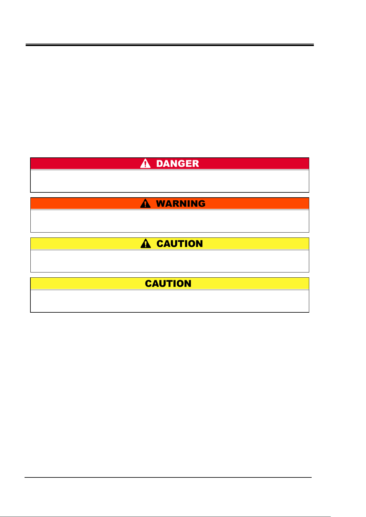
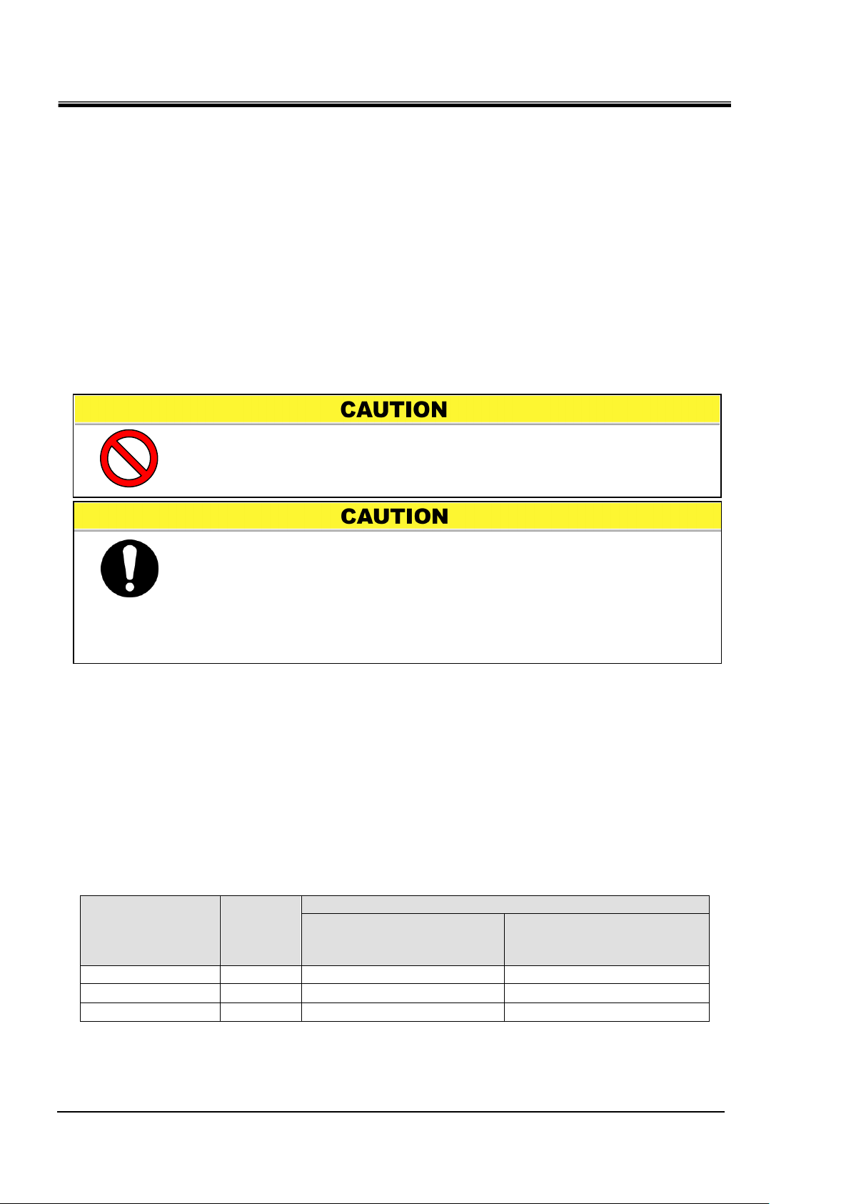
“DANGER”: Hazard that WILL cause serious personal injury or death during
operation.
“WARNING”: Hazard that MAY cause serious personal injury or death during
operation.
“CAUTION”: Hazard that MAY cause minor personal injury.
“CAUTION without exclamation symbol”: Hazard that MAY cause damage or failure
of the product, facility, devices, ect.
Chapter 1 Safety Instructions
1.3 Hazards
1.3.1 Level of hazards
The instructions given in this manual aim to assure the safe and correct
operation of the product, and to prevent injury of operators or damage to the
product. These instructions are grouped into three categories, Danger,
Warning and Caution, which indicate the level of hazard, damage and also
the degree of emergency. All safety critical information should be carefully
observed at all times.
“DANGER”, “WARNING” and “CAUTION” signs are in order according to
severity (DANGER> WARNING> CAUTION).
1.3.2 Definition of “Serious injury” and “Minor injury”
“Serious injury”
This term describes injuries that result in after effects including loss of
eyesight, burns, electrical shock, fracture, poisoning, etc. and requires
long-term treatment or hospitalization.
“Minor injury”
This term describes injuries that do not need long-term treatment or
hospitalization. (Others excluded from serious injury.)
1.3 Hazards HRSE Series
Page 9
1-3
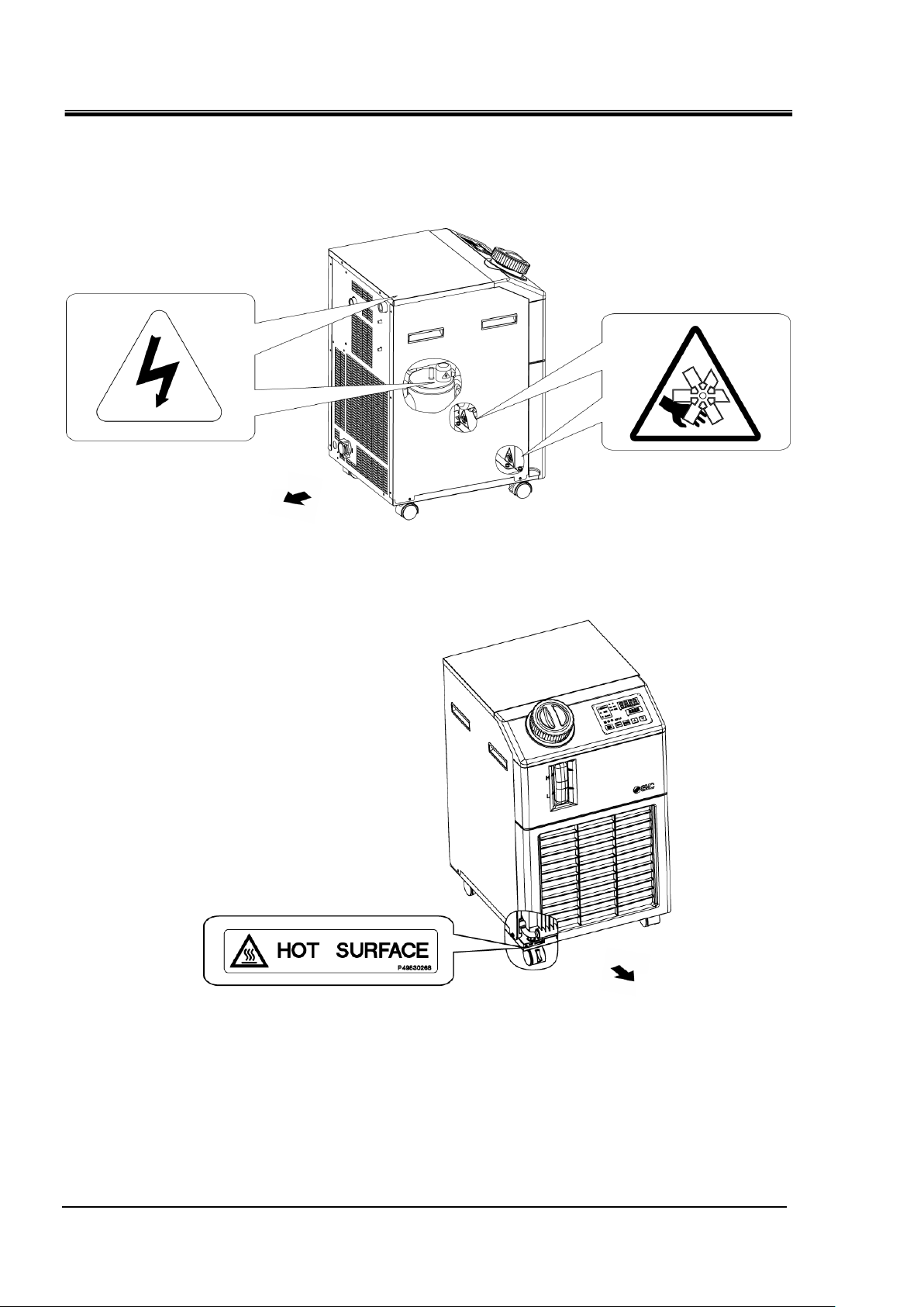
1.3.3 Types of hazard labels
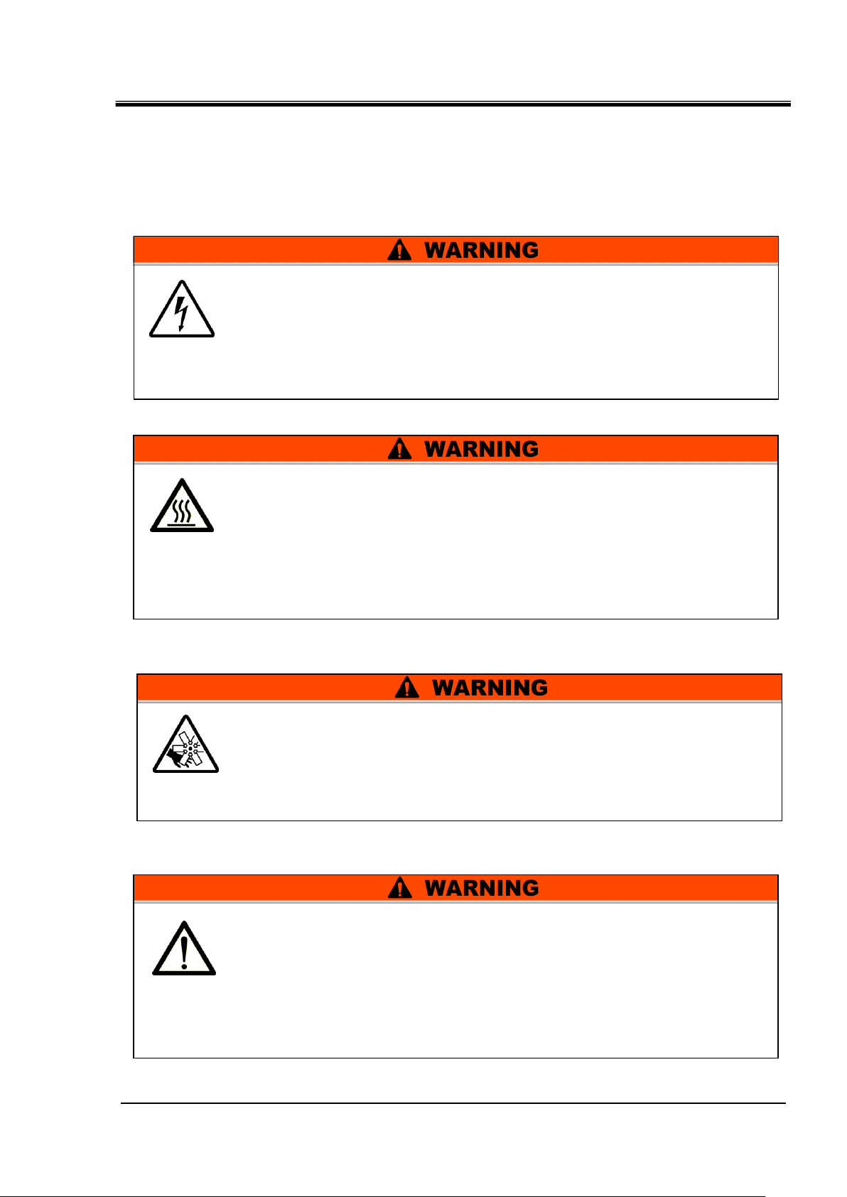
This symbol stands for general danger.
Hazards Inside
Hot Surfaces Inside – See Hot Surface symbol
Rotating Fan Inside – See Rotating Fan symbol (For air-cooled type)
Pressurized Sytem Inside – The product contains pressurised fluid
systems.
DO NOT operate the product without cover panels fitted.
This symbol stands for a possible risk of hot surface and burns.
The product has surfaces that can reach high temperatures during
operation. Even after the power is turned off, there can still be residual
heat in the product.
DO NOT operate the product without cover panels fitted.
DO NOT start working inside the product until the temperature has
decreased sufficiently.
This symbol stands for a possible risk of cutting fingers or hand, or
entanglement by rotating fan (For air-cooled type).
The product contains a cooling fan that rotates during operation of the
product.
The fan can start and stop intermittently and without warning.
DO NOT operate the product without cover panels fitted.
This symbol stands for a possible risk of electric shock.
The product is operated at high voltage and contains uncovered live
terminals inside.
DO NOT operate the product without cover panels fitted.
DO NOT work inside this product unless you have been trained to
do so.
The product has various potential hazards and they are marked with
warning labels. Be sure to read this section before starting any work on the
product.
Warning related to electricity
HRX-OM-R039
Chapter 1 Safety Instructions
Warning related to high temperatures
Warning related to rotating objects
Warning related to other general dangers
HRSE Series 1.3 Hazards
Page 10
HRX-OM-R039
1-4
Rear
Front
Chapter 1 Safety Instructions
1.3.4 Locations of Hazard Labels
There are various warning labels on the product to show the potential
hazards.
Fig. 1.3-1 Warning label position
Fig. 1.3-2 Warning label position
1.3 Hazards HRSE Series
Page 11
1-5
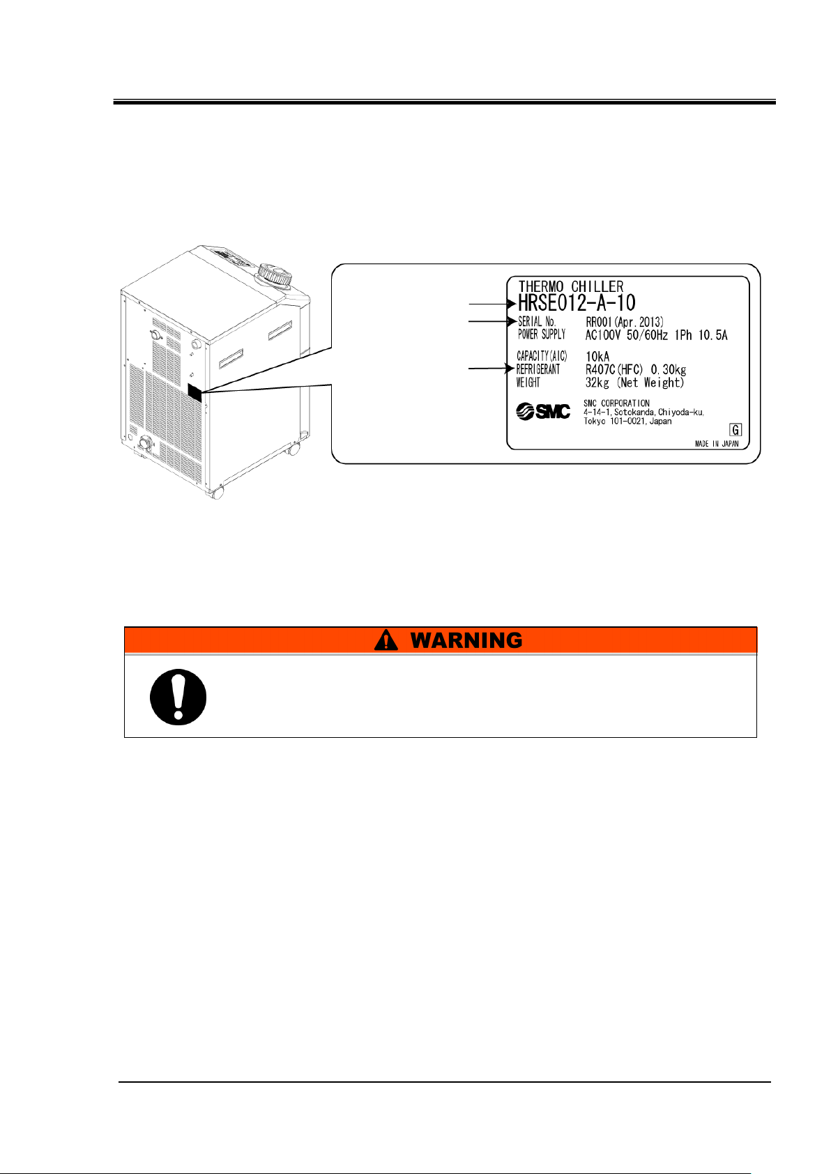
1.4 Other Labels
Follow the instructions below when using the product. Failure to
follow the instructions may cause an accident and injury.
(It is an example of model "HRSE012-A-10".)
Model Number
Serial Number
(SERIAL No.)
The type and quantity
of refrigerant
(REFRIGERANT)
1.4.1 Product Label
Information about the product, such as Serial No. and Model No. can be
found on the model label. This information is needed when contacting an
SMC sales distributor.
HRX-OM-R039
Chapter 1 Safety Instructions
Fig. 1.4-1 Position of product label
1.5 Safety Measures
1.5.1 Safety Instructions for Use
Read and understand this manual carefully before using the product.
Before starting maintenance of the product, be sure to lock out and tag out the
breaker of the user's power supply.
If operating the product during maintenance, be sure to inform all workers nearby.
Use only the correct tools and procedure when installing or maintaning the product.
Use personal protective equipment where specified (“1.5.2 Personal Protective
Equipment”)
Check all parts and screws are fitted correctly and securely after maintenance.
Avoid working in a drunken or sick condition, which might cause an accident.
Do not remove the panels except for the cases permitted in this manual.
Do not remove the panels during operation.
HRSE Series 1.4 Other Labels
Page 12
HRX-OM-R039
1-6
Always use safety shoes, gloves and head protection when
transporting, installing or uninstalling the product.
Always use safety shoes, gloves, mask, apron and eye protection
when handling the circulating fluid.
Always use safety shoes and gloves when operating the product.
Chapter 1 Safety Instructions
1.5.2 Personal Protective Equipment
This manual specifies personal protective equipment for each work.
Transport, Installing and Uninstalling
Handling of circulating fluid
Operation
1.5 Safety Measures HRSE Series
Page 13
1-7
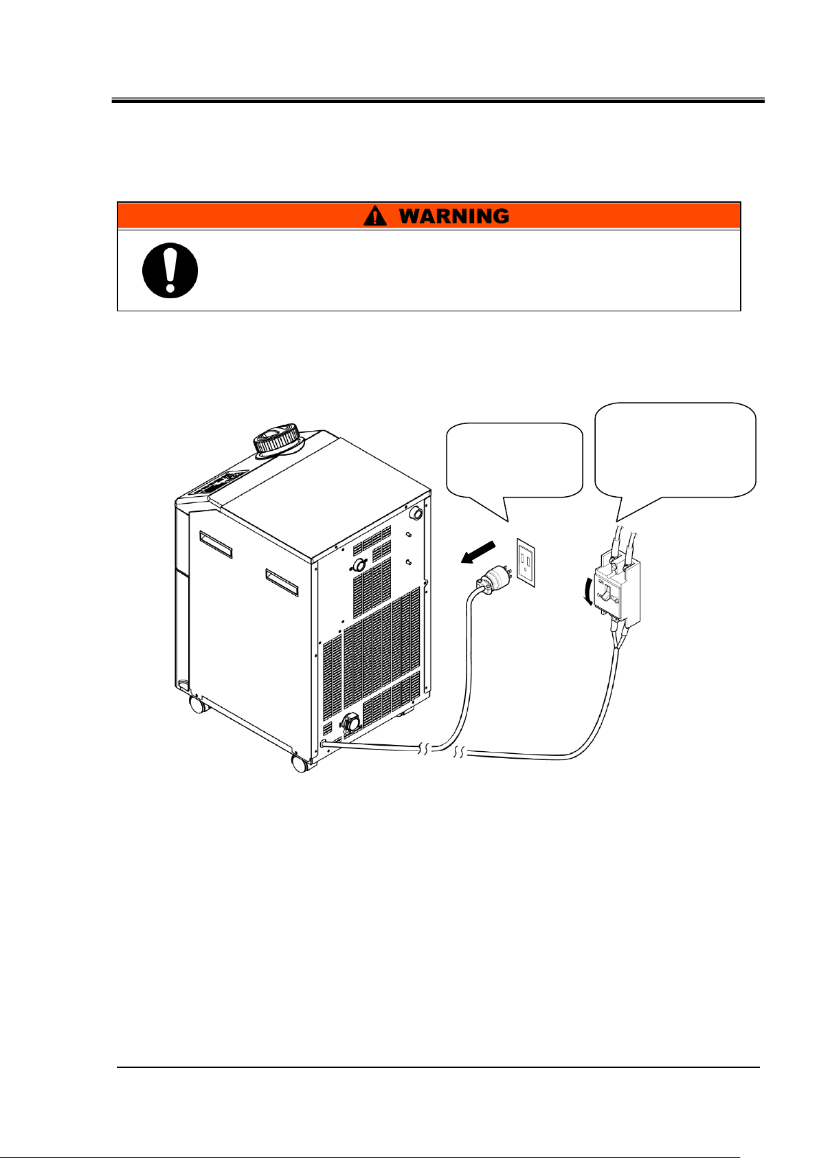
1.6 Emergency Measures
When the protective device (i.e. fuse) inside the product operates, this thermo
chiller stops operation without disconnecting the power supply. Some parts
of the thermo chiller are still being energized. Power supply to the thermo
chiller MUST be disconnected from the user's equipment.
Disconnect the
plug from an
outlet.
Turn OFF the
breaker of the power
supply source
(power supply of the
user's equipment).
In the event of natural disaster, emergency such as fire, earthquake, injury,
etc., disconnect the power supply to this product.
1. Disconnect power supply to the product.
HRX-OM-R039
Chapter 1 Safety Instructions
Fig. 1.6-1 Shut off of facility power supply 元電源の遮断 電源供給の
Fig. 1.6-2 Disconnect power supply
HRSE Series 1.6 Emergency Measures
Page 14
HRX-OM-R039
1-8
Comply with the laws and regulations in each country for the
disposal of refrigerant and compressor oil.
The release of refrigerant in to the atmosphere is banned by law.
Recover it with specific equipment and dispose of it correctly.
Only people who have sufficient knowledge and experience about
the product and its accessories are allowed to recover the
refrigerant and compressor oil.
Only maintenance personnel or qualified people are allowed to
open the cover panels of the product.
Do not mix the compressor oil with domestic waste for disposal.
Also, the disposal of the waste must only be conducted by specific
facilities that are permitted for that purpose.
Chapter 1 Safety Instructions
1.7 Waste disposal
1.7.1 Disposal of refrigerant and compressor oil
The product uses hydrofluorocarbon type refrigerant (HFC) and compressor
oil. Comply with the laws and regulations in each country for the disposal of
refrigerant and compressor oil. The type and quantity of refrigerant is
described on the 1.4.1 Product Label.
If these fluids need to be recovered, read and understand the instructions
below carefully. If there is any unclear point, contact an SMC's sales
distributor.
1.7.2 Disposal of product
The disposal of the product must be handled by a specialized industrial
waste disposal agency in accordance with local laws and regulations.
1.8 Material Safety Data Sheet (MSDS)
If the material safety data sheets of chemicals used in this product are
needed, contact an SMC's sales distributor.
Any chemicals used by the user must be accompanied by an MSDS.
1.7 Waste disposal HRSE Series
Page 15
HRX-OM-R039
2-1
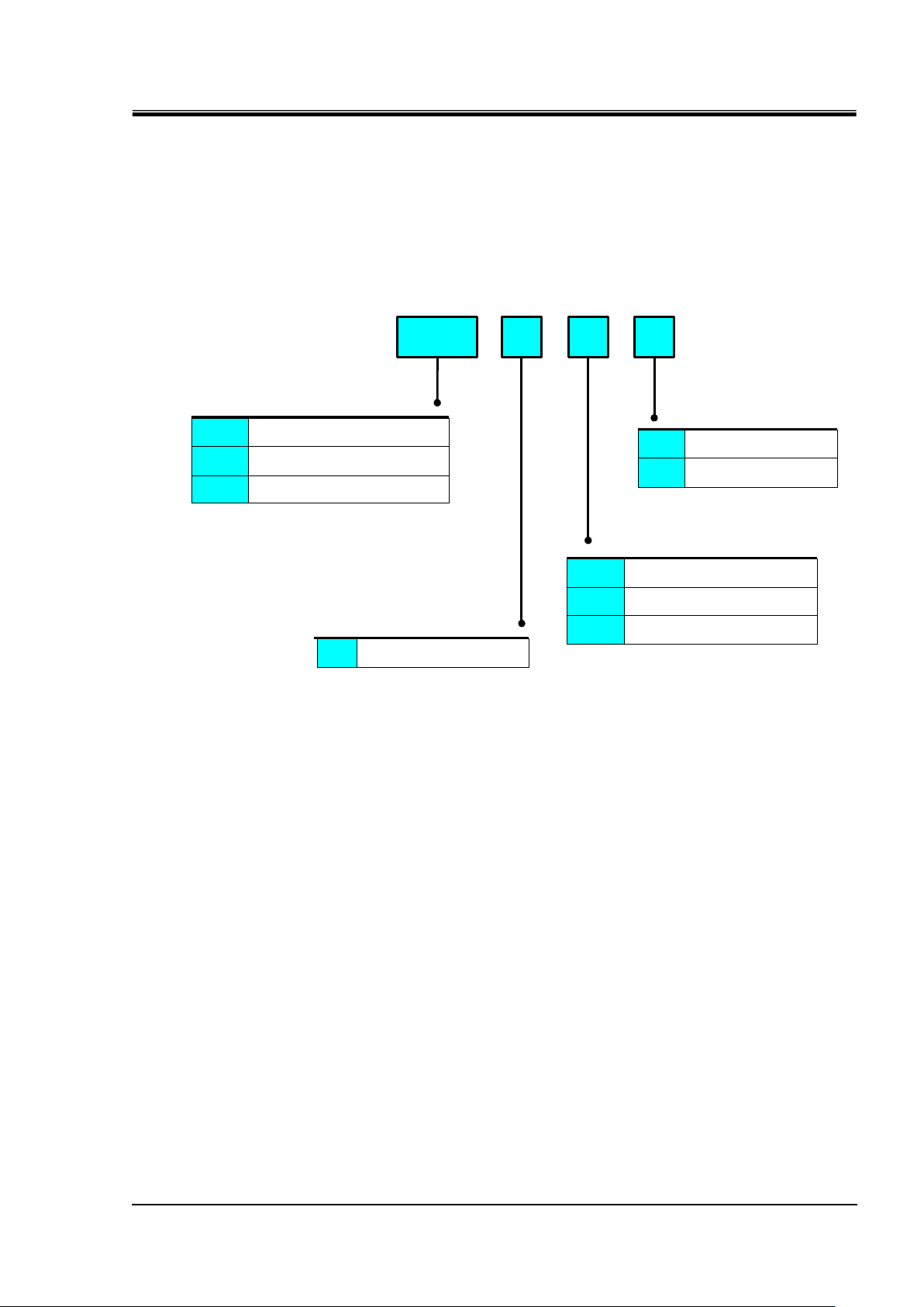
10A012HRSE
A Air-cooled refrigerator type
1) Cooling capacity
2) Cooling method
3) Power supply
- -
012 1000W/1200W (50/60Hz)
024 1900W/2200W (50/60Hz) *1
20 1-phase AC200V (50/60Hz)
*1 3)Power supply:-10(100V Type)can not be chosen.
-
4) Option
None
Nil
High-pressure pump
mounted
T
10 1-phase AC100V (50/60Hz)
018 1400W/1600W (50/60Hz)
23 1-phase AC230V (50/60Hz) CE
Chapter 2 Name and Function of Parts
Chapter 2 Name and Function of Parts
2.1 Part number of product
The product can be ordered with the part number configured as shown
below.
Refer to “1.4.1 Product Label” and check the part number of the product.
Fig. 2.1-1 Part number of product
HRSE Series 2.1 Part number of product
Page 16
HRX-OM-R039
2-2
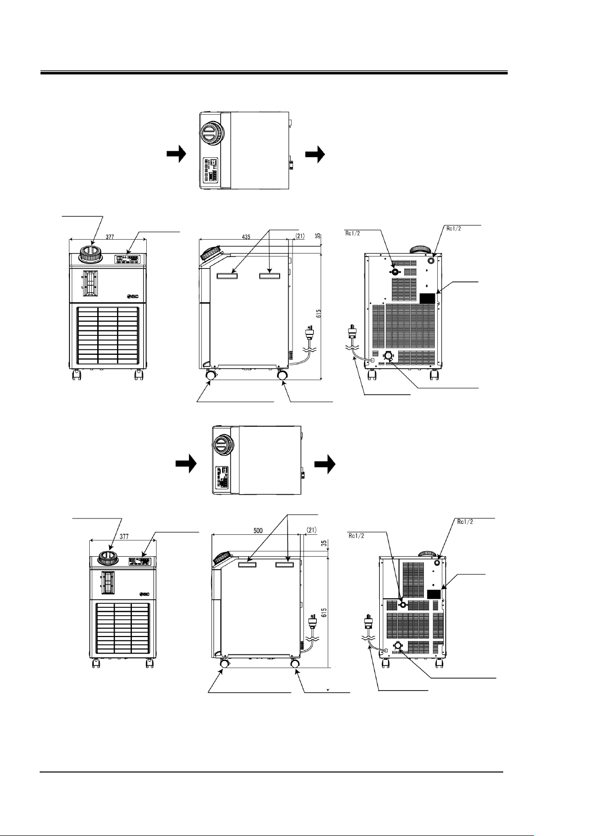
Operation
display panel
Lid for tank
Circulating fluid
return port
Circulating fluid
outlet
Model no.
label
Drain port
(with O-ring seal plug)
Ventilation air inlet
Ventilation air outlet
Caster with stopper
Caster
Power supply
Cable (3m)*
Handle
Operation
display panel
Lid for tank
Circulating fluid
outlet
Model no.
label
Drain port
(with O-ring seal plug)
Caster with stopper
Caster
Power supply
Cable (3m)*
Handle
Ventilation air inlet
Ventilation air outlet
Circulating fluid
return port
Chapter 2 Name and Function of Parts
2.2 Name and Function of Parts
Fig. 2.2-1 Names of each part
2.2 Name and Function of Parts HRSE Series
Fig. 2.2-2 Names of each part
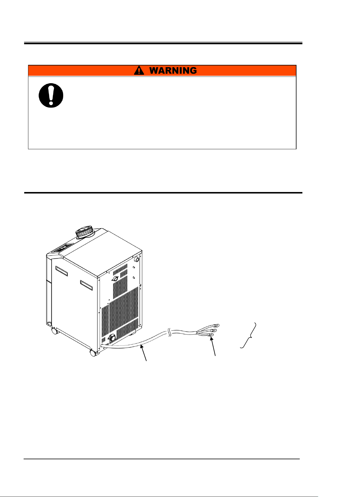
* Power supply cable terminal
- 100V power supply specification: Cable is provided with a plug with ground terminal (JIS C8303 Plug for
the receptacle with dipole grounding electrodes).
- 200/230V power supply specification: The end part of all three lead wires are untreated (bare cut).
Page 17
2-3
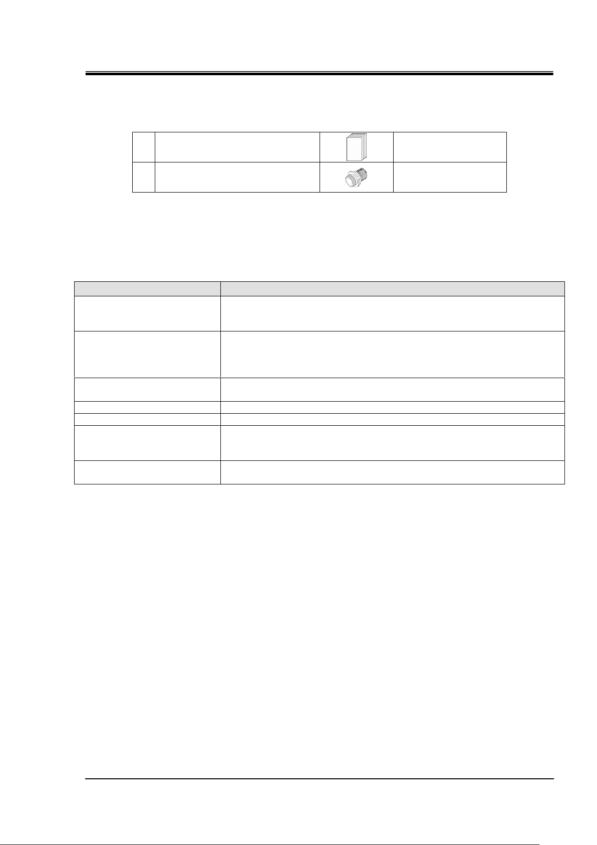
1
Operation Manual
2pcs.
(Jpn: 1pc., Eng:1pc.)
2
Fitting (for drain port)*
1pc.
Name
Function
Operation display panel
Runs and stops the product and performs settings such as the circulating
fluid temperature.
For details, refer to section ’’2.4 Operation display panel’’.
Power supply cable
For power supply of 100 V specifications, connect the plug to the outlet of
100 VAC (50/60 Hz).
For power supply of 200 V specifications, connect the plug to the breaker
(recommended size: 15 A) of the user's equipment.
Model label
Shows the part number of the product.
For details, refer to section ‘’1.4.1 Product Label’’.
Circulating fluid outlet port
The circulating fluid flows out from the outlet port.
Circulating fluid return port
The circulating fluid returns to the return port.
Drain port
This drain port to drain the circulating fluid out of the tank.
(The plug is connected to standard pump type at the time of shipment. The
ball valve is installed in the high pump head type.)
Facility water inlet
(For water-cooled type)
A facility water inlet to which the facility water is fed through piping.
The pressure of facility water should be in a range of 0.3 to 0.5MPa.
Table 2-1 Accessories list
2.3 Function of Parts
The function of parts is as follows.
Table 2-2 Function of parts
HRX-OM-R039
Chapter 2 Name and Function of Parts
HRSE Series 2.3 Function of Parts
Page 18
HRX-OM-R039
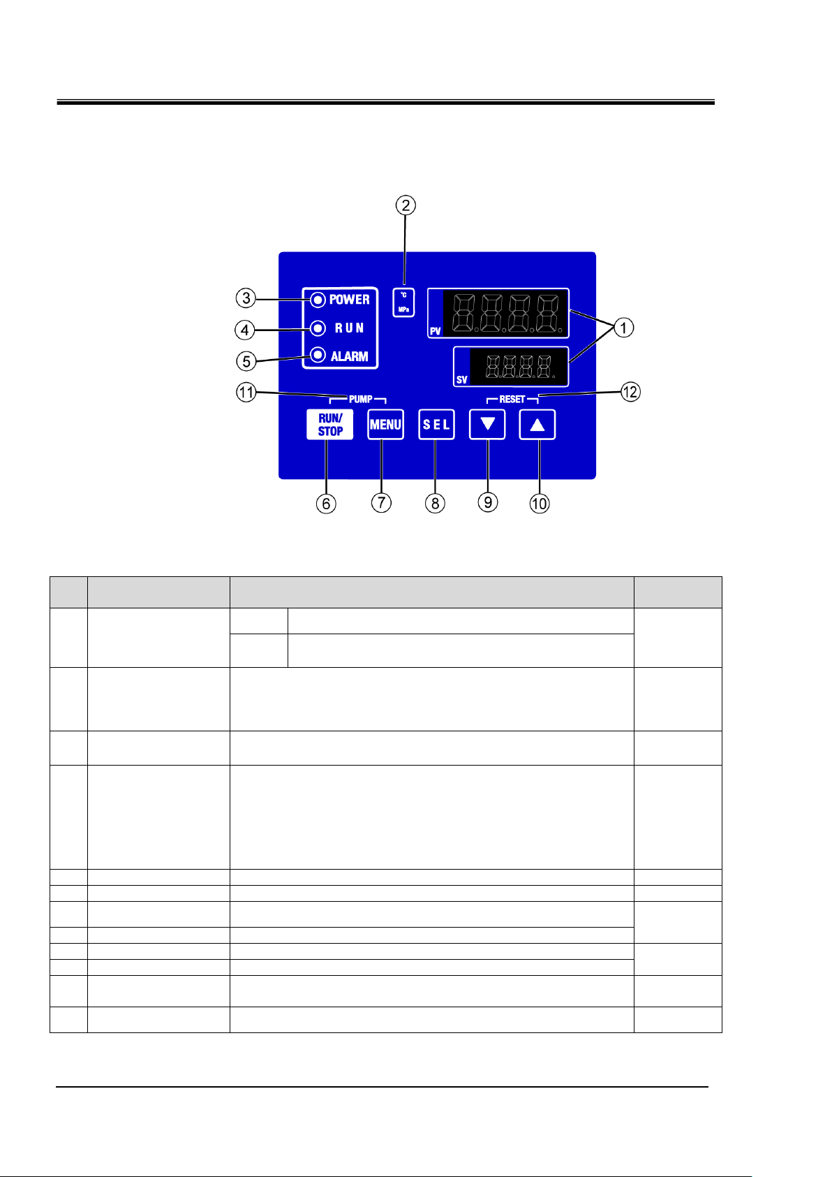
2-4
No
Description
Function
Reference
page
1
Digital display
(7 segment,
4 digits)
PV
Displays the temperature and pressure of the circulating
fluid and alarm codes.
5.2
SV
Displays the set temperature of the circulating fluid and
the set values of other menus.
2
[oC ] [MPa]lamp
[oC] light is turned on when temperature is displayed on the digital
display.
[MPa] light is turned on when pressure is displayed on the digital
display.
-
3
[POWER] lamp
Turns ON when power is being supplied.
-
4
[RUN] lamp
・Lights up when the product is started and in operation. Goes off
when the product is stopped.
・Flashes during stand-by for stop (Interval 0.5 seconds).
・Flashes during independent operation of the pump (Interval
0.3 seconds).
・Flashes during anti-freezing function (At standby: Interval 2
seconds, At operation: Interval 0.3 seconds).
4.4
5
[ALARM] lamp
Flashes with buzzer when alarm occurs (Interval 0.3 seconds).
5.3
6
[RUN/STOP] key
Makes the product start or stop.
4.4
7
[MENU] key
Shifts the main menu (display screen of temperature) the other
menu (entry of set values and monitor screen).
5.1
8
[SEL] key
Changes the item in menu and enters the set value.
9
[▼] key
Decreases the set value.
-
10
[▲] key
Increases the set value.
11
[PUMP] key
When the [MENU] and [RUN/STOP] keys are held down
simultaneously, the pump starts running independently.
4.3
12
[RESET] key
Keep the [▼] and [▲] keys pressed down simultaneously. This will
stop the alarm buzzer and reset the [ALARM] lamp.
6.3
Chapter 2 Name and Function of Parts
2.4 Operation display panel
The operation panel on the front of the product controls the basic operation
of the product.
Fig. 2.4-1 Operation display panel
Table 2-3 Operation display panel
2.4 Operation display panel HRSE Series
Page 19
HRX-OM-R039
3-1
Only persons who have sufficient knowledge and experience
about the product and system are allowed to transport and set up
the product.
Especially pay attention to personal safety.
Never lay the product on its side.
The compressor oil will leak in to the refrigerant piping, which may
cause early failure of the compressor.
Drain the residual fluid from the piping as much as possible to
prevent any spillage.
Chapter 3 Transport and Setting Up
Chapter 3 Transport and Setting Up
3.1 Transport
The product is heavy and has potential danger at transport. Also, to prevent
damage and breakage of the product, be sure to follow these instructions for
transport.
HRSE Series 3.1 Transport
Page 20
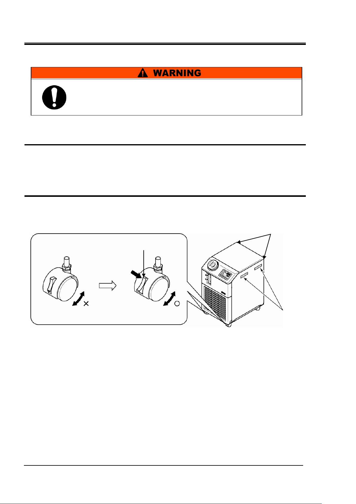
HRX-OM-R039
3-2
Handle
Unlocking
Press
Corners
This product is heavy.
Care should be taken when the product is transported on a slope.
Chapter 3 Transport and Setting Up
3.1.1 Transportation using casters
1. Release the lock levers of the front casters.
2. Push the handles on the right/left panel or the corner of the product to move the product
to the destination.
Do not hold the product by the cap to move it. This will apply excess force to the piping of
internal parts which may lead to malfunctions such as fluid leakage.
3. To push the front or rear panel, push it by the corner. Pushing by the center of the panel
may deform the shape.Care should be taken.
Fig. 3.1-1 Transportation using casters
3.1 Transport HRSE Series
Page 21
3-3
3.2 Installation
Keep the product horizontal to a rigid and flat floor which can
resist the weight of the product, and take measures to prevent the
product from tipping over. Improper installation may cause water
leakage, tipping, damage of the product or injure the operator.
Keep the ambient temperature of the product between 5 to 35oC.
Operation below 5oC may cause the compressor failure, and
operation above 35oC may cause the product to overheat and shut
down.
Power supply 200V : The operating ambient temperature is 5 to
40oC.
Do not set up the product in places possibly exposed to leakage of
flammable gas. Should any flammable gas stay around the
product, the product may cause a fire.
Do not use the product outdoors. If the product subjected to rain
or water splash it may cause electrical shock, fire or failure.
HRX-OM-R039
Chapter 3 Transport and Setting Up
3.2.1 Environment
The product must not be operated, installed, stored or transported in the
following conditions. Potential malfunction or damage to the product may
occur if these instructions are disregarded.
The product does not conform to any Clean room specifications. The pump
and ventilating fan inside the product generate particles.
Location that is outside.
Location that is exposed to water, water vapour, steam, salt water or oil.
Location that is exposed to dust or powder material.
Location that is exposed to corrosive gas, organic solvent, chemical
solution, or flammable gas (the product is not flame-proof)
Location where the ambient temperature is out of the following range:
In transportation and In storage 0 to 50°C
(with no water or circulating fluid in piping)
In operation *Power supply 100V : 5 to 35°C
*Power supply 200/230V : 5 to 40°C
Location where the ambient humidity is out of the following range or where
condensation occurs:
In transportation and storage 15 to 85%
In operation 30 to 70%
Location that is exposed to direct sunlight or heat radiation.
Location that is near heat sources and poor in ventilation.
Location that is subjected to abrupt changes in temperature.
Location that is subjected to strong electromagnetic noise (intense electric
HRSE Series 3.2 Installation
field, intense magnetic field, or surges).
Location that is subjected to static electricity, or conditions where static
electricity can discharge to the product.
Page 22
HRX-OM-R039
3-4
Model
Heat
Radiated
kW
Required ventilation amount m3/min
Differential temp. of 3 oC
between inside and
outside of installation area
Differential temp. of 6 oC
between inside and
outside of installation area
HRSE012-A-
Approx. 2
40
20
HRSE018-A-
Approx. 4
70
40
HRSE024-A-20/23
Approx. 5
90
50
Do not install in a location which can be subjected to any of the
conditions in 3.2.1 Environment.
The product radiates heat from the air vent of the cooling fan.
If the product is operated with insufficient air ventilation the internal
temperature can exceed 35oC, which can cause an overload or affect
the performance and life of the product. To prevent this ensure that
suitable ventilation is available (see below).
Power supply 200/230V : 40°C
Chapter 3 Transport and Setting Up
Location that is subjected to strong high frequencies raditation
(microwaves).
Location that is subjected to potential lightning srtike.
Location at altitude of 1000m or higher (except during product storage and
transport).
Location where the product is affected by strong vibrations or impacts.
Condition that applies external force or weight causing the product to be
damaged.
Location without adequate space for maintenance as required.
3.2.2 Location (Required ventilation rate and facility water source)
Installation of multiple products
Keep sufficient space between products so that the air vented from one product will not be taken
in by other products.
Installation Area Ventilation
① Facility having a large installation area (that can vent the air naturally)
Make an air vent on a wall at a high level and another air vent on a wall at a low level, to
allow for adequate airflow.
② Facility having a small installation area (that can not vent the air naturally)
Make a forced air exhaust vent on a wall at a high level and an air vent on a wall at a low
level.
Table 3-1 Amount of radiation and required ventilation
3.2 Installation HRSE Series
Page 23
3-5
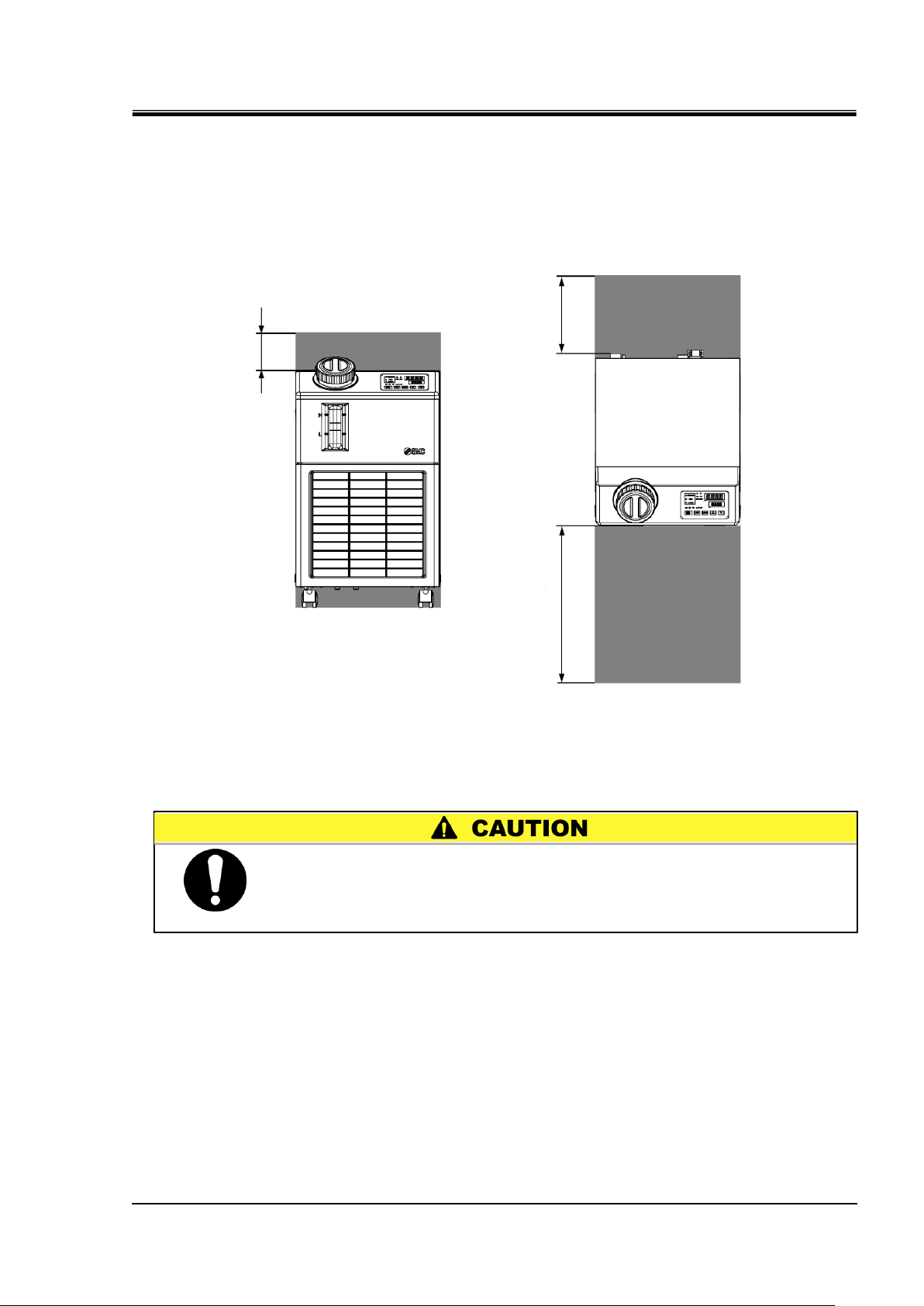
3.2.3 Installation and Maintenance Space
300mm or more
500mm or more
100mm or more
The temperature of the outlet of for the ventilation of the thermo-chiller
and the panel surface may become approx. 50oC or higher. When
placing the thermo-chiller, ensure the thermo-chiller does not affect
surrounding environment.
It is recommended to keep the space around the product shown in Fig.3.2-1
For maintenance, move the thermo-chiller into a space where maintenance
work is possible.
Fig. 3.2-1 Installation space
HRX-OM-R039
Chapter 3 Transport and Setting Up
HRSE Series 3.2 Installation
Page 24
HRX-OM-R039
3-6
Item
Part number
Anti-seismic brackets
HRS-TK003
Lock
For option T [High head pump]
Chapter 3 Transport and Setting Up
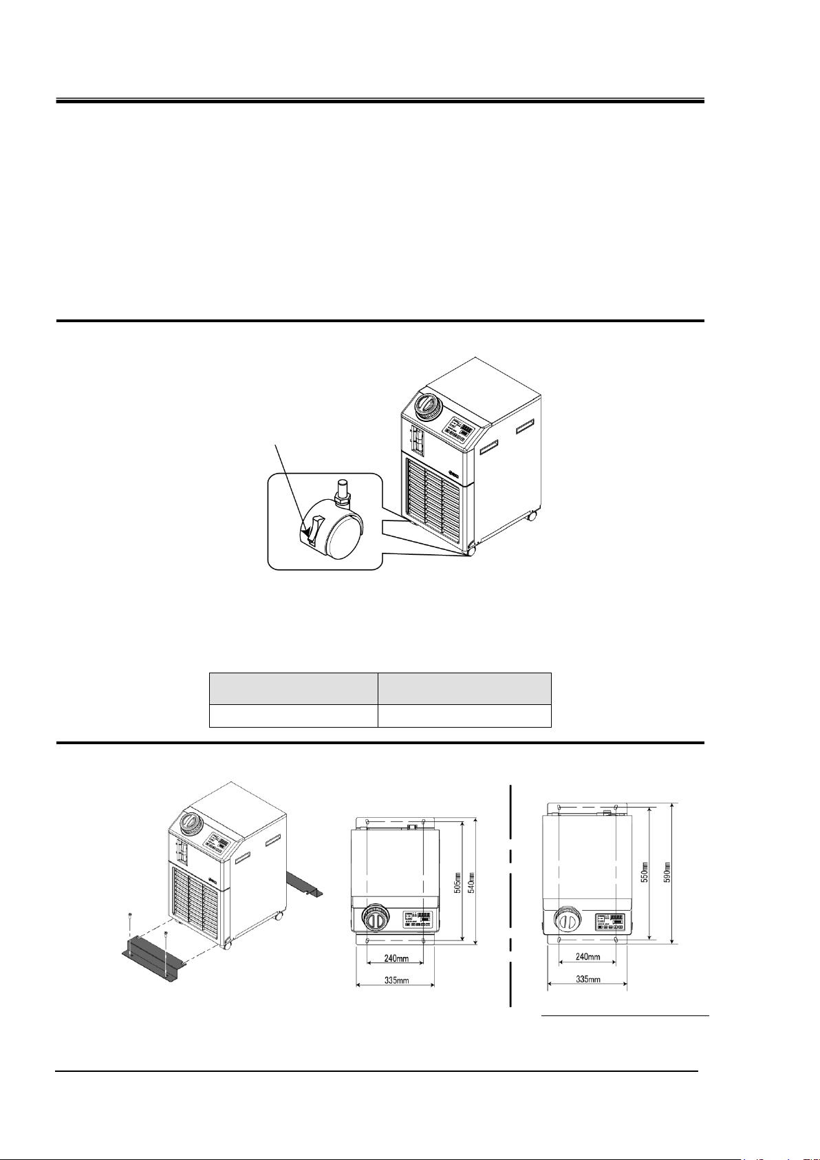
3.3 Installation
3.3.1 Mounting
Mount the product on a flat and stable floor with no vibrations.
Refer to’’8.2 Outline dimensions" for dimensional information of the
product.
How to mount the product
1. Move the product to the installation area.
2. After moving, lock the front casters again.
Fig. 3.3-1 Installation procedures
<Fixture>
Follow the procedure below when fixing the thermo-chiller to the floor or the mounting frame.
1. Prepare the fixing bracket shown below (Not included in the package).
2. Use M8 foundation bolts to fix the product within the dimensions below.
Fig. 3.3-2 Anti-seismic brackets installing
4 (four) M8 foundation bolts should be prepared by the customer.
3.3 Installation HRSE Series
Page 25
3-7
Model
Power
supply
voltage
Power supply cable spec
Recommended earth
leakage breaker
Spec.
Size
Rated
current
Terminal
configuration
(to be onnected
to the user's
equipment)
Rated
voltage
Rated
current
Sensitivity
of leak
current
HRSE012-A-10
1-phase
100V AC
(50/60Hz)
3 cores x
14AWG
(3 cores x
2.0mm2)
(including
ground)
15A
Plug with ground
terminal
(JIS C8303 Plug
for the eceptacle
for 15A and 125 V
with dipole
grounding
electrodes)
Shared
with 100
V and
200 V
15A
15mA
or
30mA
HRSE012-A-10-T
HRSE018-A-10
HRSE018-A-10-T
HRSE012-A-20/23
1-phase
200V AC
(50/60Hz)
-23 Only
1-phase
230V AC
(50/60Hz)
3 cores x
14AWG
(3 cores x
2.0mm2)
(including
ground)
15A
Lead wire end not
treated
(Bare cut)
(L: White,
N: Black,
E: Green)
Shared
with 100
V, 200
V and
230V
15A
30mA
HRSE012-A-20/23-T
HRSE018-A-20/23
HRSE018-A-20/23-T
HRSE024-A-20/23
HRSE024-A-20/23-T
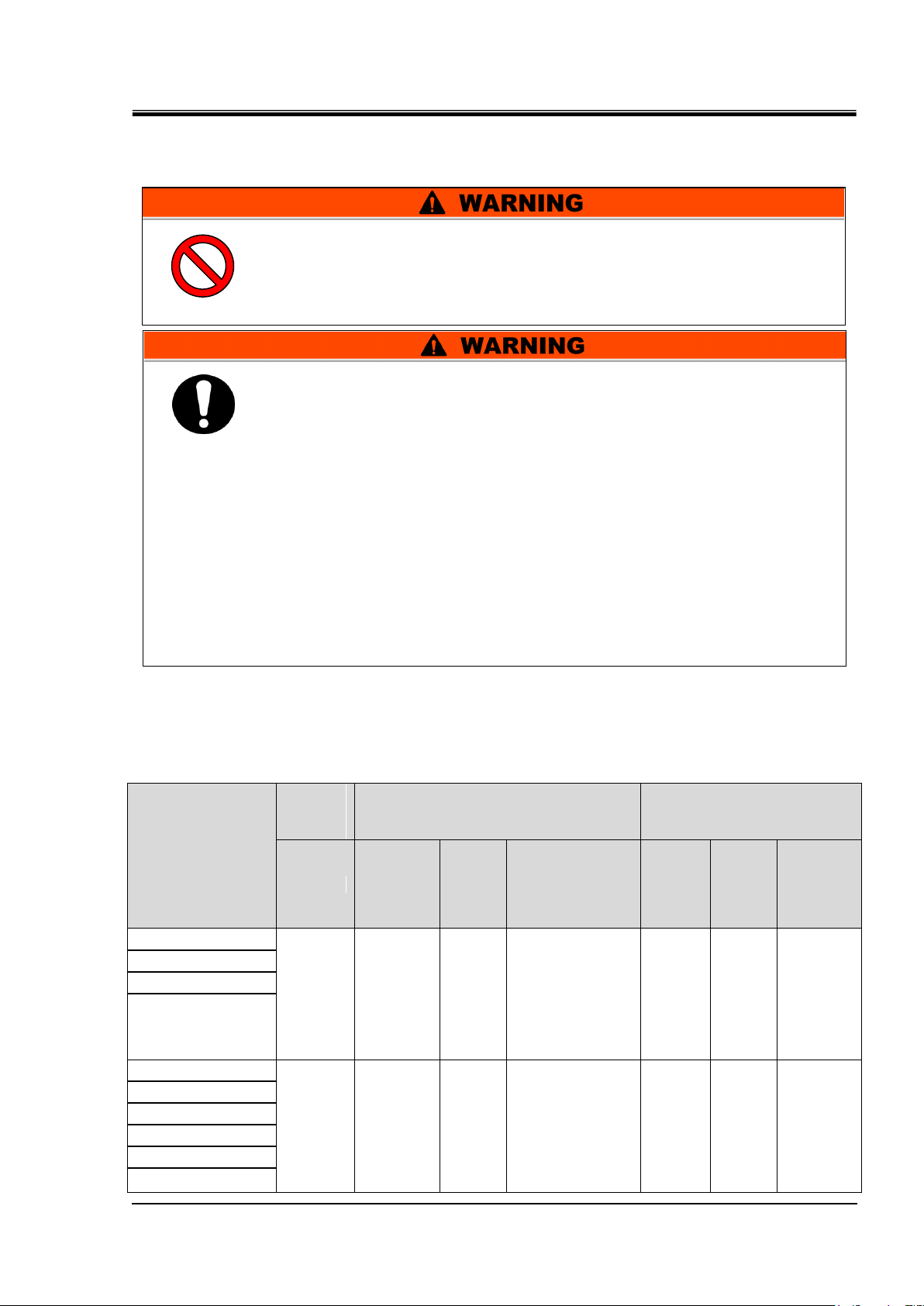
Only qualified persons are allowed to wire the product.
Be sure to shut off the user’s power supply. Wiring with the
product energized is strictly prohibitted.
The wiring must be secured to the product to prevent the external
force of cables being applied to the terminals. Incomplete wiring or
improper securing of wiring may cause electrical shock, excessive
heat and fire.
Ensure a stable power supply with no voltage surges.
Ensure that an Earth Leakage Breaker is used in the power supply
of the product. See “Table 3-2”.
Use a power supply suitable for the specifications of the product.
Be sure to connect the ground connection.
Ensure that a lock out facility is availble on the power supply.
Each product must have its own separate Earth Leakage Breaker.
Otherwise there can be a risk of electric shock or fire.
Do not modify the intenal electrical wiring of the product. Incorrect
wiring may cause electrical shock or fire. Also, modifing the
internal wiring will void the product’s warranty.
Do not connect the ground to water line, gas pipe or lightening
conductor.
3.3.2 Electrical wiring
HRX-OM-R039
Chapter 3 Transport and Setting Up
Power supply cable and Earth Leakage Breaker
Prepare the power supply shown in the following table. For the connection
between the product and power supply, use the power supply cable and
Table 3-2 Power supply cable and Earth Leakage Breaker (Recommended)
HRSE Series 3.3 Installation
earth leakage breaker shown below.
Page 26
HRX-OM-R039
3-8
Cable
The electrical facilities should be installed and wired in
accordance with local laws and regulations of each country and by
a person who has knowledge and experience.
Check the power supply. Operation with voltages, capacities and
frequencies other than the specified values can cause fire and
electrical shock.
Wire with an applicable cable size and terminal. Forcibly mounting
with an unsuitable size cable may result in heat generation or fire
Crimped terminal
(Prepared by customer)
L (White)
Earth leakage
breaker
(Secondary side)
N (Black)
E (Green)
Chapter 3 Transport and Setting Up
3.3.3 Preparation and wiring of power supply cable
Preparation 【For power supply : 200/230V 】
1. Strip the sheath from the cable of the product.
2. Connect the other end of the cable to a terminal (e.g. crimped terminal) that is compatible to the
secondary side of the earth leakage breaker of the user's equipment.
Fig. 3.3-3 Power supply cable
3.3 Installation HRSE Series
Page 27
HRX-OM-R039
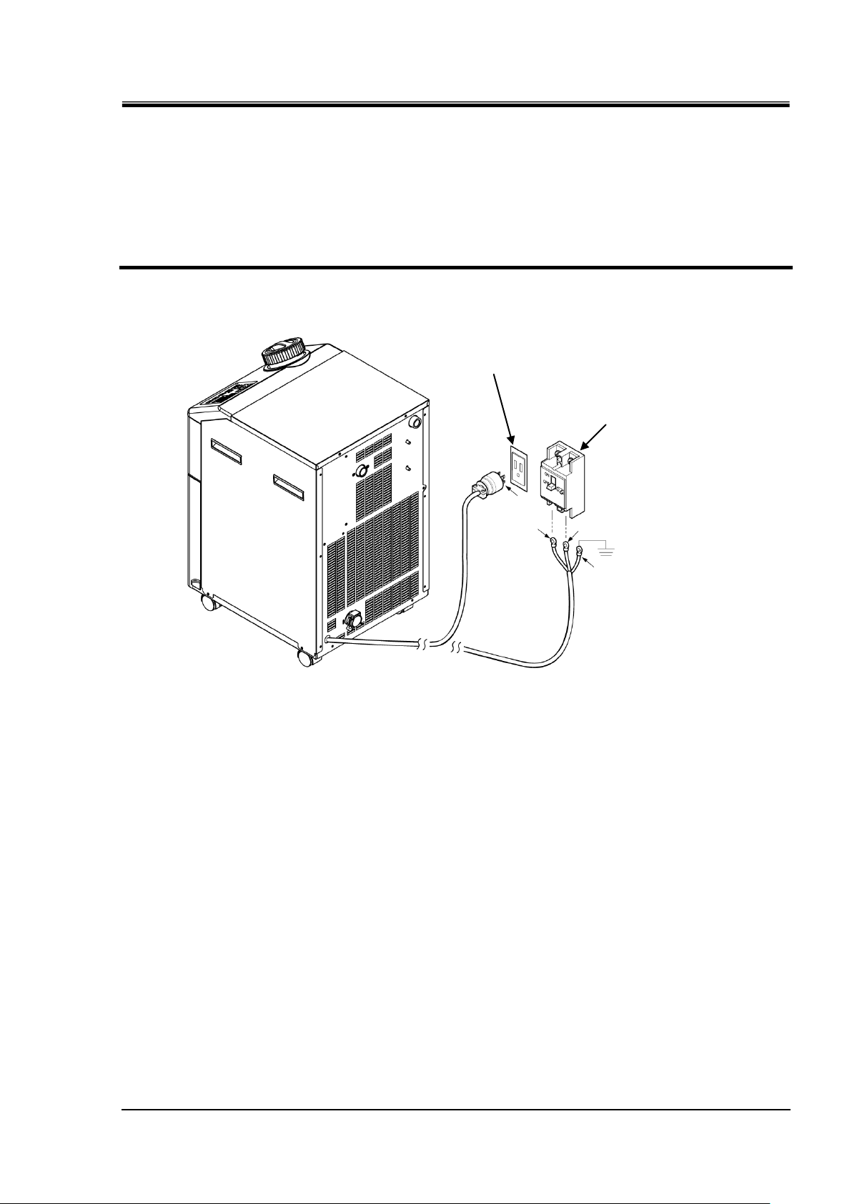
3-9
L
N E Earth
Earth leakage
breaker
E
Grounded socket
Chapter 3 Transport and Setting Up
Connecting [For power supply : 100V, 200V and 230V]
1. Connect the plug or crimped terminal to the outlet with ground or to the secondary side
of the electrical leakage breaker and to the grounding.
2. Plug the power supply cable in to the power cable connector on the product.
Fig. 3.3-4 Wiring of power supply
HRSE Series 3.3 Installation
Page 28
HRX-OM-R039
3-10
Name
Port size*1
Recommended
tightening torque
Recommended proof
pressure for piping
Circulating fluid supply
Rc1/2
28 to 30N・m
0.3MPa more
(For option T [High head pump] :
0.4MPa more)
Circulating fluid return
Rc1/2
28 to 30N・m
0.3MPa more
(For option T [High head pump] :
0.4MPa more)
Connect piping firmly. Incorrect piping might cause leakage of
supplied or drained leakage and wet surrounding area and facility.
Pay attention not to allow dust and foreign materials to enter into
water circuit etc. during connection of piping.
Hold the piping port firmly with specific wrench when tightening.
The piping should be selected with due consideraton of pressure and
temperature. Otherwise, the piping can burst in service.
Do not use the materials that rust or corrode for the circulating fluid
circuits. Using the materials that tend to rust or corrode may cause
clogs or/and leakages of the circulating fluid circuits. In case of
using these kind of materials, consider and carry out some
prevention against the rusting or corrosion by the customer side.
Do not generate a rapid change of pressure by water hammer etc.
The product and external piping might be damaged.
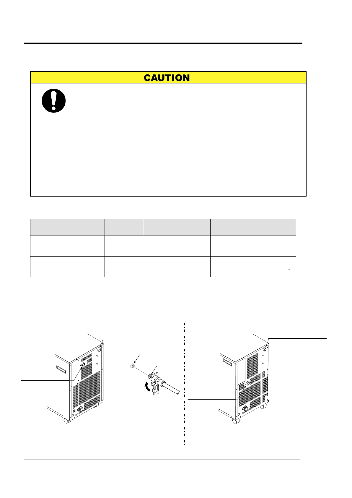
Circulating fluid return port
Rc1/2
Circulating fluid outlet
Rc1/2
Piping port
Circulating fluid return port
Rc1/2
Circulating fluid outlet
Rc1/2
Chapter 3 Transport and Setting Up
3.4 PIPING
Piping port size
Table 3-3 Piping port size
How to connect piping
Tighten the piping to circulating fluid outlet / return port and facility water outlet / inlet.
3.4 PIPING HRSE Series
Fig. 3.4-1 Tightening of piping
Page 29

3-11
Recommended piping circuit
No.
Name
Size
1
Valve
Rc1/2
2
Y-shaped strainer or filter
Rc1/2 (#40) Rc1/2 (500μm)
3
Flow meter
0 to 30 L/min
4
Others (Pipe, hose, etc.)
I.Dφ15more
Circulating fluid
Return
Circulating fluid
Outlet
Load device
Fig. 3.4-2 Recommended piping circuit
HRX-OM-R039
Chapter 3 Transport and Setting Up
HRSE Series 3.4 PIPING
Page 30

HRX-OM-R039
3-12
Item
No
Remarks
Ethylene glycol aqueous solution 60%
HRZ-BR001
Please dilute to 15% with tap
water and use it.
Densitometer
HRZ-BR002
-
Tank lid
Circulating fluid fill
Liquid level
Check the drain port is plugged or closed by the valve to prevent the
supplied circulating fluid from draining out.
Supply the circulating fluid up to the “H” mark on the tank.
If the liquid level in the tank becomes lower than the "L" level or the
circulating fluid flow becomes 4L/min or less, the thermo chiller stops
operation.
Chapter 3 Transport and Setting Up
3.5 Fill of circulating fluid
Turn the tank lid anticlockwise to open. Supply the circulating fluid up to the
“H” mark on the fluid level indicator. Use tap water which satisfies the water
quality standard shown inTable 7-1, or a 15% aqueous solution of ethylene
glycol.
Fig. 3.5-1 Circulating fluid fill
15% aqueous solution of ethylene glycol
When a 15% aqueous solution of ethylene glycol is used, prepare the ethylene glycol aqueous
solution separately.
To control the concentration of the ethylene glycol aqueous solution, a concentration meter is available
separately from SMC.
3.5 Fill of circulating fluid HRSE Series
Page 31

Chapter 4 Starting the Product
4-1
Only people who have sufficient knowledge and experience about the
product and its accessories are allowed to start and stop the product.
Chapter 4 Starting the Product
4.1 Before Starting
Check the following items before starting the product.
Installation conditions
Check the product is installed horizontally.
Check that there are no heavy objects on the product, and the external
piping is not applying excessive force to the product.
Connection of cables
Check the power cables are correctly connected.
Circulating fluid
HRX-OM-R039
Check proper connection of piping at inlet and outlet.
Fluid level indicator (for tank)
Ensure that the fluid level is on “H”.
HRSE Series 4.1 Before Starting
Page 32

HRX-OM-R039
4-2
Press
L
N E Earth
Earth leakage
breaker
E
Grounded socket
Chapter 4 Starting the Product
4.2 Preparation for Start
4.2.1 Power supply
Turn ON the electrical leakage breaker of the user's equipment, and supply
power to the thermo chiller.
* For 100 V power supply specification, connect the plug to the outlet with
grounding (JIS C8303 Plug for the receptacle for 15A and 125 V with dipole
grounding electrodes).
When the product is switched on, the operation panel displays the following
conditions.
The initial screen (HELLO screen) is displayed for 8 seconds on the operation
display panel. Then, the display changes to the main screen which displays
the circulating fluid outlet temperature.
The set value of circulating fluid temperature is displayed as SV on the panel.
The present value of circulating fluid temperature is displayed as PV on the
panel.
Fig. 4.2-1 Power supply
4.2.2 Setting of circulating fluid temperature
4.2 Preparation for Start HRSE Series
Press the [▼] and [▲] buttons on the operational panel to change the SV to
required value.
Fig. 4.2-2 Setting of circulating fluid temperature
Page 33

HRX-OM-R039
4-3
If leakage occurs due to faulty piping including an opened fitting of eternal piping,
stop manual operation of the pump and fix the leak.
Flash
Press together
Chapter 4 Starting the Product
4.3 Preparation of circulating fluid
When the circulating fluid tank is filled the user’s machine and piping remains
empty. In that condition, the circulating fluid flows out to the user’s machine
and piping and the tank level decreases and may require a refill. In that case,
refill the circulating fluid in the following procedure.
1. Press the [PUMP] key on the operation display panel (press the [RUN/STOP] key and
[MENU] key simultaneously).
The pump operates independently while the [PUMP] key is pressed. The [RUN] lamp
(green) flashes while the pump is operating independently, and the circulating fluid in
the tank is supplied to the customer’s device and piping. This can be done to check for
leakage, and to discharge air from the piping.
When the fluid level in the tank drops below the "L" level, stop the operation of the
pump itself, and add some circulating fluid into the tank. Repeat the same sequence
after adding the fluid until the fluid level in the tank stops decreasing. When the liquid
level in the tank stops decreasing, it means that the circulating fluid is filled completely
in the piping of the user's facility.
Fig. 4.3-1 Manual operation of the pump
HRSE Series 4.3 Preparation of circulating fluid
Page 34

HRX-OM-R039
4-4
Confirm that the drain port is closed with a plug or a valve to avoid
discharging the circulating fluid that is added to the tank from the
drain port.
Supply the circulating fluid up to the “H” mark on the tank.
Tank lid
Filling of Circulating Fluid
Liquid
Chapter 4 Starting the Product
2. Open the tank lid and supply the circulating fluid up to the “H” mark on the tank.
Fig. 4.3-2 Filling of Circulating Fluid
4.3 Preparation of circulating fluid HRSE Series
Page 35

4-5
4.4 Starting and Stopping
Press
When an alarm occurs Refer to “Chapter 6 Alarm indication and trouble
shooting’’
Allow at least five minutes before restarting the product.
ON
4.4.1 Starting the product
Before starting, check the items specified in “4.1 Before Starting”
If any alarm lamp remains on, refer to Chapter 6 Alarm indication and
trouble shooting”
1. Press the [RUN/STOP] key on the operation panel.
The [RUN] lamp lights up (in green) and the product starts running. The circulating
discharge temperature (PV) is controlled to the set temperature (SV).
HRX-OM-R039
Chapter 4 Starting the Product
Fig. 4.4-1 Starting the product
HRSE Series 4.4 Starting and Stopping
Page 36

HRX-OM-R039
4-6
Except in case of emergency, do not turn off the power supply switch
until the product has stopped completely. Doing so could cause
failure.
Be sure to shut off the breaker of the facility power supply (the user’s
machine power supply) before wiring.
Also, drain the circulating fluid, etc. from the product in accordance
with and put into storage properly
(Referring to "7.4.1 Discharge of the circulating fluid".)
Flash
OFF
Press
Chapter 4 Starting the Product
4.4.2 Stopping the product
1. Press the [RUN/STOP] button on the operation panel.
The [RUN] lamp on the operation panel flashes green at 1 second intervals, and
continues operation to prepare to stop. After approx. 15 seconds, the [RUN] lamp goes
off and the product stops.
Fig. 4.4-2 Stopping the product
2. Turn OFF the electrical leakage breaker of the user's equipment, and disconnect the
power supply to the thermo chiller.
4.4 Starting and Stopping HRSE Series
Page 37

4-7
4.5 Check items after starting
When an Alarm is seen, press the [STOP] button and then turn off the
power supply switch to stop the product, and turn off the breaker of
the user’s power supply to isolate the product.
Check the following items after starting the product.
There is no leakage from piping.
There is no drain of circulating fluid from the drain port.
The tank level is within the specified range.
4.6 Adjustment of Circulating Fluid
Flow adjustment
HRX-OM-R039
Chapter 4 Starting the Product
If the flow rate is less than 5L/min it will not be able to achieve the specified
cooling capacity. The adjustment of flow rate should be performed using a
manual bypass valve and monitoring the pressure or flow rate in the
customer’s device, referring to the recommended piping flow shown in
Figure 3.4-2, until they reach the required value.
When the flow rate of the circulating fluid becomes 4L/min. or lower, a
protective device of the thermo chiller operates to stop it's operation.
("AL07" alarm will be generated.)
Please reconsider the piping of the equipment that the product is
connected to, or consider using the "Bypass piping set; HRS-BP001"
that is available as an option.
HRSE Series 4.5 Check items after starting
Page 38

HRX-OM-R039
4-8
Chapter 4 Starting the Product
4.6 Adjustment of Circulating Fluid HRSE Series
Page 39

Chapter 5 Display and setting of various functions
5-1
NO
Function
Outline
Reference
page
1
Main display
Displays the current temperature of the circulating fluid, discharge pressure of
the circulating fluidhange the circulating fluid temperature.
5.2
2
Alarm display
menu
Indicates alarm number when an alarm occurs.
5.3
3
Inspection
monitor menu
Product temperature, pressure and accumulated operating time can be
checked as daily inspection. Use these for daily inspection.
5.4
4
Setting of alarm
buzzer
Alarm sound can be set to on/off.
5.5
5
Alarm
customizing
Operation during alarm condition and threshold values can be changed
depending on the alarm type.
5.6
6
Data reset
Functions can be reset to the default settings (settings when shipped from the
factory).
5.7
7
Accumulation
time reset
Reset function when the pump, the fan, or the compressor is replaced.
Accumulated time is reset.
5.8
8
Reset after
power failure
Start operation automatically after the power supply is turned on.
5.9
Read and understand this manual carefully before changing the
settings.
Chapter 5 Display and setting of
various functions
5.1 Function
5.1.1 Key operations
HRX-OM-R039
The product can have the displays and settings shown in table 5-1.
Table 5-1 List of function
HRSE Series 5.1 Function
Page 40

HRX-OM-R039
5-2
PV
SV
Unused
SEL
Main display
Unused
Check monitor menu
PV
SV
PV
SV
PV
SV
PV
SV
PV
SV
PV
SV
PV
SV
PV
SV
PV
SV
PV
SV
Setting menu
PV
SV
PV
SV
PV
SV
PV
SV
PV
SV
PV
SV
PV
SV
PV
SV
PV
SV
PV
SV
PV
SV
PV
SV
PV
SV
Alarm
(The latest)
Alarm
Alarm display menu
Alarm
(The oldest)
PV
SV
PV
SV
PV
SV
MENU
MENU
Press the
2sec.
PV
SV
PV
SV
PV
SV
PV
SV
Power supply ON
PV
SV
PV
SV
Unused
PV
SV
PV
SV
PV
SV
SEL
SEL
SEL
SEL
SEL
MENU MENU
MENU MENU
SEL
SEL
SEL
SEL
SEL
SEL
SEL
SEL
SEL
SEL
SEL
SEL
SEL
SEL
SEL
SEL
SEL
SEL
SEL
SEL
SEL
SEL
SEL
SEL
SEL
SEL
SEL
SEL
SEL
SEL
PV
SV
PV
SV
PV
SV
SEL
SEL
SEL
Circulating
fluid outlet
temperature
Circulating
fluid set
temperature
Note) It changes only when the
alarm is generated.
Circulating
fluid outlet
temperature
Temperature
of the
compressor
inlet.
Unused
Pressure of
higher
pressure
refrigerant
circuit
Pressure of
lower
pressure
refrigerant
circuit
Unused
Accumulated
operation
time of the
pump
Accumulated
operation
time of the
fun motor
Accumulated
operation
time of the
compressor
Accumulated
operation
time
Press the
2sec.
Unused
Unused
Unused
Unused
Unused
Unused
Unused
Unused
Recover
from power
failure
Unused
Unused
Unused
Unused
Data reset
Pump
accumulated
operating
time reset
Fan motor
accumulated
operating
time reset
Compressor
accumulated
operating
time reset
Unused
Unused
Unused
Unused
Unused
Press the
2sec.
Chapter 5 Display and setting of various functions
5.1.2 Key operations
Fig. 5.1-1 “Key operation (1/2)” and
Fig. 5.1-2 “Key operation (2/2)” show the operation of keys of the
thermo-chiller.
5.1 Function HRSE Series
Fig. 5.1-1 Key operation (1/2)
Page 41

HRX-OM-R039
5-3
Alarm setting menu
PV
SV
PV
SV
PV
SV
PV
SV
PV
SV
PV
SV
PV
SV
PV
SV
PV
SV
PV
SV
PV
SV
PV
SV
Unused
Communication
setting menu
Unused
Unused
Unused
Unused
Unused
Unused
Unused
Unused
Unused
Unused
Unused
Unused
Unused
Unused
Unused
Unused
PV
SV
PV
SV
PV
SV
PV
SV
PV
SV
PV
SV
PV
SV
PV
SV
PV
SV
PV
SV
PV
SV
PV
SV
PV
SV
PV
SV
PV
SV
PV
SV
PV
SV
PV
SV
PV
SV
PV
SV
PV
SV
PV
SV
PV
SV
Unused
Unused
Unused
PV
SV
PV
SV
SV
Unused
Unused
PV
SV
PV
SV
Unused
Unused
Unused
Unused
PV
SV
PV
SV
PV
SV
PV
SV
PV
SV
Unused
PV
SV
PV
SV
PV
SV
PV
SV
PV
SV
PV
SV
MENU MENU
MENU
SEL
SEL
SEL
SEL
SEL
SEL
SEL
SEL
SEL
SEL
SEL
SEL
SEL
SEL
SEL
SEL
SEL
SEL
SEL
SEL
SEL
SEL
SEL
SEL
SEL
SEL
SEL
SEL
SEL
SEL
SEL
SEL
SEL
SEL
SEL
SEL
SEL
SEL
SEL
SEL
SEL
SEL
SEL
SEL
SEL
SEL
SEL
SEL
SEL
SEL
SEL
PV
Unused
Unused
PV
SV
SEL
PV
SV
SEL
PV
SV
SEL
SEL
Unused
Alarm
buzzer
sound
Unused
Changing of
circulating fluid
discharge
temperature rise
Detection
temperature for
circulating fluid
discharge
temperature rise
Changing of
circulating fluid
discharge
temperature drop
Detection
temperature for
circulating fluid
discharge
temperature drop
Unused
Unused
Unused
Unused
Unused
Unused
Unused
Unused
Unused
Unused
Unused
Unused
Unused
Unused
Temperature
alarm
Monitoring
method
Monitoring
start timer
Range over
Detection timer
Press the
2sec.
Unused
MENU
Press the
2sec.
Chapter 5 Display and setting of various functions
HRSE Series 5.1 Function
Fig. 5.1-2 Key operation (2/2)
Page 42

HRX-OM-R039
5-4
Display
Item
Initial value
(Default setting)
Reference
page
Category
Temperature
Circulating fluid temperature
(TEMP PV)
5.2
Main display
Circulating fluid set temperature (TEMP
SV)
20 oC
Unused
-
Unused
X X
Alarm no. 5.3
Alarm
display
menu
Circulating fluid outlet temperature
5.4
Check
monitor
menu
Unused
Temperature of the compressor inlet.
Unused
Pressure of higher pressure refrigerant
circuit
Pressure of lower pressure refrigerant
circuit
Unused
Accumulated operation time of the pump
Accumulated operation time of the fun
motor
Accumulated operation time of the
compressor
Accumulated operation time
Unused
-
-
Setting
menu
Unused
- Unused
- Unused
-
Unused
-
Unused
- Unused
- Unused
- Recover from power failure
OFF
5.9
Unused
-
-
Unused
- Unused
- Pressure unit
- Data reset
NO
5.7
Pump accumulated operating time reset
NO
5.8
Fun motor accumulated operating time
reset
NO
Compressor accumulated operating
time reset
NO
Unused
-
-
Unused
-
Unused
-
Unused
-
Unused
-
Chapter 5 Display and setting of various functions
5.1.3 List of parameters
Table 5.1-2“List of parameter (1/3)” and Table 5.1-4“List of parameter (3/3)”
show the parameters of the thermo-chiller.
Table 5.1-2 List of parameter (1/3)
5.1 Function HRSE Series
Page 43

HRX-OM-R039
5-5
Display
Item
Initial value
(Default setting)
Reference
page
Category
Alarm buzzer sound
ON
5.5
Alarm setting
menu
Unused
-
5.6
Changing of circulating fluid discharge
temperature rise
A.RUN
Detection temperature for circulating
fluid discharge temperature rise
35 oC
Changing of circulating fluid discharge
temperature drop
A.RUN
Detection temperature for circulating
fluid discharge temperature drop
1 oC
Unused
-
-
Unused
- Unused
- Unused
- Unused
- Unused
- Unused
- Unused
-
Unused
-
Unused
- Unused
- Unused
- Unused
- Unused
-
Temperature alarm
Monitoring method
0
5.6
Monitoring start timer
----
Range over
Detection timer
5
Unused
-
-
-
Unused
- Unused
- Unused
-
Unused
-
Unused
- Unused
- Unused
- Unused
- Unused
- Unused
- Unused
- Unused
- Unused
-
Unused
- Unused
-
Unused
-
Unused
- Unused
- Unused
- Unused
-
Chapter 5 Display and setting of various functions
Table 5.1-3 List of parameter (2/3)
HRSE Series 5.1 Function
Page 44

HRX-OM-R039
5-6
Display
Item
Initial value
(Default setting)
Reference
page
Category
Unused
-
-
-
Unused
-
Unused
-
Unused
-
Unused
-
Unused
-
Unused
-
Unused
-
Unused
-
Unused
-
Chapter 5 Display and setting of various functions
Table 5.1-4 List of parameter (3/3)
5.1 Function HRSE Series
Page 45

Chapter 5 Display and setting of various functions
5-7
PV
SV
PV
SV
PV
SV
Current discharge temperature
Set Temperature
5.2 Main screen
5.2.1 Main screen
Displays the current temperature and the set temperature of the circulating
fluid. The set temperature can be changed on this screen.
5.2.2 Display on the main screen
The display on the main screen is as follows.
Current discharge temperature of circulating fluid Display
1. Connect the plug of the power supply cable to an outlet to supply power.
Current temperature and set temperature are displayed on the digital display.
Alarm display screen (See 5.3) appears when an alarm is generated.
Circulating fluid temperature Set
HRX-OM-R039
2. Change the set temperature by pressing the [▼][▲] key.
After changing the set temperature, set it by pressing the [SEL] key.
The set value flashes while it is being changed.
If [SEL] key is not pressed, the value is reset after 3 sec.
Circulating fluid discharge pressure Diaplay
3. Press the [SEL] key.
"P1" is displayed, but this feature is not available on this product.
Electric resistivity Display
4. Press the [SEL] key.
"dl" is displayed, but this feature is not available on this product.
HRSE Series 5.2 Main screen
Page 46

HRX-OM-R039
5-8
PV
SV
PV
SV
PV
SV
PV
SV
PV
SV
PV
SV
Alarm code
Alarm history
[SEL]
[MENU]
Alarm
release
Chapter 5 Display and setting of various functions
5.3 Alarm display menu
5.3.1 Alarm display menu
The alarm display screen appears when an alarm is generated.
The alarm display menu cannot be accessed when no alarm has been
generated.
Refer to “Chapter 6 Alarm indication and trouble shooting” for the content
of alarms.
5.3.2 Content of display of alarm display menu
The alarm display screen appears when an alarm is gernerated.
When multiple alarms are generated, the latest alarm is displayed on the
screen.
Each time the [SEL] key is pressed, the alarms are displayed in order,
starting from the latest one.
The main screen is displayed when the alarm is reset.
The main screen is displayed when [MENU] key is pressed while an alarm is
output.
The alarm display screen is displayed if [MENU] key is pressed again.
5.3 Alarm display menu HRSE Series
Page 47

Chapter 5 Display and setting of various functions
5-9
Display
Item
Contents
Circulating fluid outlet temperature
Displays the temperature of the circulating fluid outlet.
This temperature does not take offset into
consideration.
Circulating fluid return
port temperature
Displays the temperature of the circulating fluid return.
Temperature of the inlet of the
compressor
Displays the temperature of the inlet of the compressor.
Circulating fluid outlet pressure
Displays the circulating fluid outlet pressure at the
outlet.
Pressure of higher pressure
refrigerant circuit
Displays the pressure of higher pressure side of the
refrigerant circuit.
Pressure of lower pressure
refrigerant circuit
Displays the pressure of lower pressure side of the
refrigerant circuit.
Electric resistivity
Displays the electric resistivity.
Accumulated operation time of the
pump
Displays the accumulated operation time of the pump.
Accumulated operation time of the
fun motor
Displays the accumulated operation time of the fan
motor. (For air-cooled type)
Accumulated operation time of the
compressor
Displays the accumulated operation time of the
compressor.
Accumulated operation time
Displays the accumulated operation time.
PV
SV
PV
SV
PV
SV
[MENU]
Press and
5.4 Inspection monitor menu
5.4.1 Inspection monitor menu
As a part of the daily inspection, the temperature, pressure and accumulated
operating time can be checked.
Please use this for confirmation of your daily inspection.
5.4.2 Checking of the Inspection monitor menu
The table below explains the check items of the inspection monitor menu.
Table 5.4-1 List of check items of Inspection monitor menu
HRX-OM-R039
Check of the circulating fluid outlet temperature
1. Press and hold the [MENU] key for approx. 2 sec.
The temperature of the circulating fluid outlet 「 」is displayed on the digital display.
Displays the temperature of the circulating fluid at the outlet from which the fluid is fed to
the customer’s device.
2. Press the [SEL] key once.
"t2" is displayed, but this feature is not available on this product.
HRSE Series 5.4 Inspection monitor menu
Page 48

HRX-OM-R039
5-10
PV
SV
PV
SV
PV
SV
PV
SV
PV
SV
Chapter 5 Display and setting of various functions
Check of the temperature of the inlet of the compressor.
3. Press the [SEL] key once.
The temperature of the refrigerant circuit compressor inlet is displayed on the digital
display.
Displays the temperature of the compressor inlet.
4. Press the [SEL] key once.
"P1" is displayed, but this feature is not available on this product.
Check of the pressure of the higher pressure side of the refrigerant circuit
5. Press the [SEL] key once.
The pressure of higher pressure refrigerant circuit is displayed on the digital display.
Displays the pressure of the higher pressure side of the refrigerant circuit.
Check of the pressure of the lower pressure side of the refrigerant circuit
6. Press the [SEL] key once.
The pressure of lower pressure refrigerant circuit is displayed on the digital display.
Displays the pressure of the lower pressure side of the refrigerant circuit.
Displayed only when the compressor is operating.
7. Press the [SEL] key once.
"d1" is displayed, but this feature is not available on this product.
5.4 Inspection monitor menu HRSE Series
Page 49

5-11
Check of the accumulated operation time of the pump
PV
SV
Cumulative time
Indicated value
0h to 999h
to
1,000h to 99,999h
to
100,000h
Return to
PV
SV
PV
SV
PV
SV
8. Press the [SEL] key once.
The accumulated operation time of the pump is displayed on the digital display.
Displays the accumulated operation time of the pump. Refer to the table below for the display.
AL28 Pump maintenance alarm is generated when the accumulated operation time of the
pump reaches 20,000 hours ( ) or more. For details, refer to Chapter 6 Alarm
indication and trouble shooting.
Check of the accumulated operation time of the fan motor
HRX-OM-R039
Chapter 5 Display and setting of various functions
Table 5.4-2 List of time display
9. Press the [SEL] key once.
The accumulated operation time of the fun motor is displayed on the digital display.
Displays the accumulated operation time of the fan motor. Refer to Table 5.4-2 for the display.
AL29 Fan motor maintenance alarm is generated when the accumulated operation time of
the fan motor reaches 20,000 hours ( ) or more. For details, refer to Chapter 6
Alarm indication and trouble shooting.
Check of the accumulated operation time of the compressor
10. Press the [SEL] key once.
The accumulated operation time of the compressor is displayed on the digital display.
Displays the accumulated operation time of the compressor. Refer to Table 5.4-2 for the
display.
AL30 Compressor maintenance alarm is generated when the accumulated operation time
of the compressor reaches 50,000 hours ( ) or more. For details, refer to
Chapter 6 Alarm indication and trouble shooting.
Check of the accumulated operation time
11. Press the [SEL] key once.
The accumulated operation time is displayed on the digital display.
Displays the accumulated operation time. Refer to Table 5.4-2 for the display.
HRSE Series 5.4 Inspection monitor menu
Page 50

HRX-OM-R039
5-12
Display
Item
Contents
Initial value
(Default setting)
Alarm buzzer sound
Sets alarm buzzer sound.
ON
PV
SV
PV
SV
PV
SV
PV
SV
Set value
Explanation
Initial value
(Default setting)
No alarm buzzer sound
Alarm buzzer sound
✓
PV
SV
[MENU]
Press
and hold
[MENU]
Press
and hold
[MENU]
Press
and hold
Chapter 5 Display and setting of various functions
5.5 Alarm buzzer sound setting
5.5.1 Alarm buzzer sound setting
This sets whether a warning sound is made or not when alarm signal is
output.
The default setting is buzzer sound ON.
5.5.2 Alarm buzzer sound setting and checking
The table below explains the setting items of the alarm buzzer sound and the
initial values.
Table 5.5-1 List of set alarm buzzer sound
1. Press and hold the [MENU] key for approx. 2 sec.
Repeat pressing the key until the setting screen for alarm buzzer sound [ ]
appears on the digital display.
Alarm buzzer sound Setting and checking
2. Select alarm buzzer sound from the table below with [▲] key or [▼] key, and confirm by
pressing “SEL”.
Table 5.5-2 List of set value
3. Press the [MENU] key once.
Return to the main screen (screen displaying the circulating fluid temperature).
5.5 Alarm buzzer sound setting HRSE Series
Page 51

Chapter 5 Display and setting of various functions
5-13
Display
Item
Contents
Initial value
(Default setting)
Changing of circulating
fluid discharge
temperature rise
Set the operation when alarm No. AL03
"circulating fluid discharge temperature rise" is
generated.
A.RUN
Detection temperature for
circulating fluid discharge
temperature rise
Sets the detection temperature for the alarm of
alarm NO. AL03 "circulating fluid discharge
temperature rise ".
Alarm signal is generated when the temperature
becomes higher than this temperature.
35 oC
Changing of circulating
fluid discharge
temperature drop
Set the operation when alarm No. AL04"
circulating fluid discharge temperature drop “is
generated.
A.RUN
Detection temperature for
circulating fluid discharge
temperature drop
Sets the detection temperature for the alarm of
alarm NO. AL04 "circulating fluid discharge
temperature drop ".
Alarm signal is generated when the temperature
becomes lower than this temperature.
1 oC
Temperature alarm
Monitoring method
One alarm monitoring method can be selected
from four methods for AL04 "Detection temp for
the circulating fluid discharge temp. increase"
and AL06 "Detection temp. for circulating fluid
discharge temp. drop".
0
5.6 Alarm customize function
5.6.1 Alarm customize function
The operation and the threshold when alarm signal is output can be
customized. Customers should set them depending on their applications.
The alarms below can be customized.
●AL03 Circulating fluid discharge temp. rise (Refer to Table 5.6-3 and Table 5.6-4)
Operation: When this alarm signal is output, user can choose to
stop/continue operation, or not to detect this alarm.
"Operation continue" is default setting.
Threshold change: Temp. setting at which the alarm is generated can be
changed, and also, the alarm generating conditions can be set.
HRX-OM-R039
“35oC" is default setting.
●AL04 Circulating fluid discharge temp. (Refer to Table 5.6-5 and Table 5.6-6)
Operation: When this alarm signal is output, user can choose to
stop/continue operation, or not to detect this alarm.
"Operation continue" is default setting.
Threshold change: Temp. setting at which the alarm is generated can be
changed, and also, the alarm generating conditions can be set.
“1oC" is default setting.
5.6.2 Alarm customize function setting and checking
The table below explains the setting items of the alarm customize function
and the initial values.
Table 5.6-1 List of set alarm customize function(1/2)
HRSE Series 5.6 Alarm customize function
Page 52

HRX-OM-R039
5-14
Display
Item
Contents
Initial value
(Default setting)
Monitoring start timer
Alarm will not be generated during the set period
of time after starting operation. Alarm monitoring
starts when it reaches the set time.
----
Range over
Detection timer
After starting the alarm monitoring, the alarm will
not be generated right away and will be kept not
generated for the set period of time for AL04
"Detection temp for the circulating fluid discharge
temp. increase" and AL06 "Detection temp. for
circulating fluid discharge temp. drop", when the
temperatures goes out of the set range.
5
PV
SV
PV
SV
PV
SV
PV
SV
PV
SV
PV
SV
Set value
Explanation
Initial value
(Default setting)
This alarm signal is not detected.
Operation continues when this alarm signal is
generated.
✓
Operation is stopped when this alarm signal is
generated.
[MENU]
Press and
hold
[MENU]
Press and
hold
[MENU]
Press and
hold
Chapter 5 Display and setting of various functions
Table 5.6-2 List of set alarm customize function(2/2)
1. Press and hold the [MENU] key for approx. 2 sec.
Repeat pressing the key until the setting screen for alarm buzzer sound [ ]
appears on the digital display.
2. Press the [SEL] key once.
"AS02" is displayed, but this feature is not available on this product.
Changing of circulating fluid discharge temperature rise Setting and checking
3. Press the [SEL] key once.
The set screen of changing of circulating fluid discharge temperature rise is displayed on
the digital display.
4. Select changing of circulating fluid discharge temperature rise from the table below with
[▲] key or [▼] key, and confirm by pressing “SEL”.
Table 5.6-3 List of set value
5.6 Alarm customize function HRSE Series
Page 53

HRX-OM-R039
5-15
PV
SV
Set value
Explanation
Initial value
(Default setting)
Setting/checking are not available if the setting of the
circulating fluid discharge temperature rise is OFF.
Centigrade
to
Sets detection temp for the circulating fluid discharge
temperature rise.
Temperature unit is Centigrade : Setting unit is 1oC
PV
SV
Set value
Explanation
Initial value
(Default setting)
This alarm signal is not detected.
Operation continues when this alarm signal is
generated.
✓
Operation is stopped when this alarm signal is
generated.
PV
SV
Chapter 5 Display and setting of various functions
Detection temperature for circulating fluid discharge temperature rise Setting and checking
5. Press the [SEL] key once.
The set screen of detection temperature for circulating fluid discharge temperature rise is
displayed on the digital display.
6. Select detection temperature for circulating fluid discharge temperature rise from the
table below with [▲] key or [▼] key, and confirm by pressing “SEL”.
Table 5.6-4 List of set value
Changing of circulating fluid discharge temperature drop setting and checking
7. Press the [SEL] key once.
The set screen of changing of circulating fluid discharge temperature drop is displayed
on the digital display.
8. Select changing of circulating fluid discharge temperature drop from the table below with
[▲] key or [▼] key, and confirm by pressing “SEL”.
Table 5.6-5 List of set value
Detection temperature for circulating fluid discharge temperature drop Setting and checking
9. Press the [SEL] key once.
The set screen of detection temperature for circulating fluid discharge temperature drop
is displayed on the digital display.
HRSE Series 5.6 Alarm customize function
Page 54

HRX-OM-R039
5-16
Set value
Explanation
Initial value
(Default setting)
Setting/checking are not available if the setting of
the circulating fluid discharge temperature drop is
OFF.
Centigrade
to
Sets detection temp for the circulating fluid
discharge temperature drop.
Temperature unit is Centigrade : Setting unit is 1oC
PV
SV
PV
SV
PV
SV
PV
SV
Chapter 5 Display and setting of various functions
10. Select detection temperature for circulating fluid discharge temperature drop from the
table below with [▲] key or [▼] key, and confirm by pressing “SEL”.
Table 5.6-6 List of set value
11. Press the [SEL] key once.
"AS07" is displayed, but this feature is not available on this product.
12. Press the [SEL] key once.
"AS08" is displayed, but this feature is not available on this product.
13. Press the [SEL] key once.
"AS09" is displayed, but this feature is not available on this product.
14. Press the [SEL] key once.
"AS10" is displayed, but this feature is not available on this product.
5.6 Alarm customize function HRSE Series
Page 55

5-17
PV
SV
PV
SV
PV
SV
PV
SV
PV
SV
PV
SV
15. Press the [SEL] key once.
"AS11" is displayed, but this feature is not available on this product.
16. Press the [SEL] key once.
"AS12" is displayed, but this feature is not available on this product.
17. Press the [SEL] key once.
HRX-OM-R039
Chapter 5 Display and setting of various functions
"AS13" is displayed, but this feature is not available on this product.
18. Press the [SEL] key once.
"AS14" is displayed, but this feature is not available on this product.
19. Press the [SEL] key once.
"AS15" is displayed, but this feature is not available on this product.
20. Press the [SEL] key once.
"AS16" is displayed, but this feature is not available on this product.
HRSE Series 5.6 Alarm customize function
Page 56

HRX-OM-R039
5-18
PV
SV
PV
SV
PV
SV
PV
SV
PV
SV
Chapter 5 Display and setting of various functions
21. Press the [SEL] key once.
"AS17" is displayed, but this feature is not available on this product.
22. Press the [SEL] key once.
"AS18" is displayed, but this feature is not available on this product.
23. Press the [SEL] key once.
"AS19" is displayed, but this feature is not available on this product.
24. Press the [SEL] key once.
"AS20" is displayed, but this feature is not available on this product.
How to monitor the temperature alarm Setting and Checking
25. Press the [SEL] key once.
Setting screen of the temperature alarm monitoring method is displayed on the digital
display.
5.6 Alarm customize function HRSE Series
Page 57

HRX-OM-R039
5-19
Set value
Item
Explanation
Initial value
(Default setting)
Continuous
monitoring
Alarm monitoring starts at the same
time as it is turned ON.
✓
Automatic
monitoring
When the circulating fluid
temperature is outside of the alarm
threshold range at the time of
operation start, the alarm will not be
generated until the temperature
comes inside the alarm threshold
range.
Monitoring start
timer
Alarm will not be generated until it
reaches the time set for the AS.22
"Monitoring start timer" after the
operation starts.
Alarm monitoring starts when it
reaches the set time.
Automatic
monitoring +
Monitoring start
timer
Alarm will not be generated until it
reaches the time set for the AS.22
"Monitoring start timer" after the
operation starts.
Alarm monitoring starts when it
reaches the set time.
When the circulating fluid
temperature enters the alarm
threshold range before it reaches
the set time, the alarm monitoring
will be started at that time.
PV
SV
Set value
Explanation
Initial value
(Default setting)
Setting and checking are impossible when "0:
Continuous monitoring" or "1: Automatic
monitoring" is selected for the setting of AS21
"Temperature alarm monitoring method".
✓
Chapter 5 Display and setting of various functions
26. Select temperature alarm monitoring method from the table below with [▲] key or [▼]
key, and confirm by pressing “SEL”.
Table 5.6-7 List of set value
Settings of this function and example of alarm generating timing for 5.6.3 "Setting of temperature alarm
monitoring method and generation timing".
Monitoring start timer Setting and Checking
27. Press the [SEL] key once.
Setting screen of the monitoring start timer is displayed on the digital display.
28. Select monitoring start timer from the table below with [▲] key or [▼] key, and confirm
by pressing “SEL”.
HRSE Series 5.6 Alarm customize function
Table 5.6-8 List of set value
Page 58

HRX-OM-R039
5-20
to
Sets the time when alarm monitoring starts
Setting unit is 1 minute.
PV
SV
Set value
Explanation
Initial value
(Default setting)
to
Sets time from detecting the alarm to
generation of the alarm.
Setting unit is 1 second.
PV
SV
Chapter 5 Display and setting of various functions
Settings of this function and example of alarm generating timing for 5.6.3 "Setting of
temperature alarm monitoring method and generation timing".
Range over detection timer; Setting and Checking
29. Press the [SEL] key once.
Setting screen of the range over detection timer is displayed on the digital display.
30. Select range over detection timer from the table below with [▲] key or [▼] key, and
confirm by pressing “SEL”.
Table 5.6-9 List of set value
Settings of this function and example of alarm generating timing for 5.6.3 "Setting of
temperature alarm monitoring method and generation timing".
31. Press the [MENU] key once.
Return to the main screen (screen displaying the circulating fluid temperature).
5.6 Alarm customize function HRSE Series
Page 59

HRX-OM-R039
5-21
Thermo chiller
Run
Stop
Circulating fluid
set temperature 15
o
C
AS.04 Alarm monitoring
OFF
Alarm
Generation
Nothing
AS.04
set temperature 20 oC
AS.06
set temperature 10 oC
AS.06 Alarm monitoring
Elapsed time
600sec
ON
(2)
300sec
400sec
(3)
(4)
(5)
Circulating fluid
temperature
(1)
ON
OFF
Chapter 5 Display and setting of various functions
5.6.3 Setting of temperature alarm monitoring method and alarm
generation timing
Examples of temperature alarm monitoring method setting and alarm
generation timing are shown below.
When "Automatic monitoring" is selected
[1] Circulating fluid temperature when starting operation: Approximately 25 oC
[2] Circulating fluid set temperature: 15 oC
[3] "AS.21: Temperature alarm monitoring method": Select "Automatic monitoring".
("----" (invalid setting) will be shown for "AS.22: Monitoring start timer".)
[4] "AS.04: Detection temp. for the circulating fluid discharge temp. increase": Set to "20 oC".
[5] "AS.06: Detection temp. for the circulating fluid discharge temp. drop": Set to "10 oC".
[6] "AS.23: Range over detection timer "Set to "600 sec".
Fig 5.6-1 Alarm generation timing
-Alarm generation timing
Status (1): Temperature alarm monitoring starts by starting the chiller operation. As the
circulating fluid temperature at this time is 20 oC, "AS.06" starts alarm monitoring
at the same time as the operation start.
Status (2): The circulating fluid temperature becomes within the set range of "AS.04", and
starts "AS.04" alarm monitoring".
Status (3): The circulating fluid temperature exceeds the threshold of "AS.06", but the alarm
will not be generated as it has returned within the 600 sec range of the "AS.23:
Range over detecting timer".
Status (4): The circulating fluid temperature exceeds the threshold of "AS.04", but the alarm
will not be generated as it has returned within the 600 sec range of the "AS.23:
Range over detecting timer".
Status (5): Alarm "AL03: Circulating fluid discharge temp. increase" will be generated after
600 seconds that is set for the "AS.23: Range over detection timer" after the
circulating fluid temperature exceeds the threshold of "AS.04".
HRSE Series 5.6 Alarm customize function
Page 60

HRX-OM-R039
5-22
Thermo chiller
Run
Stop
Circulating fluid
set temperature 15 oC
AS.04 Alarm monitoring
ON
OFF
Alarm
Generation
Nothing
ON
OFF
AS.04
set temperature 20 oC
AS.06
set temperature 10 oC
AS.06 Alarm monitoring
600sec
(2)
300sec
400sec
(3)
(4)
(6)
Circulating fluid
temperature
(1)
50min
(5)
Elapsed time
Chapter 5 Display and setting of various functions
When "Automatic monitoring + Monitoring start timer" is selected
[1] Circulating fluid temperature when starting operation: Approximately 25 oC
[2] Circulating fluid set temperature: 15 oC
[3] "AS.21: Temperature alarm monitoring method": Select "Automatic monitoring + Monitoring
start timer".
[4] "AS.22: Monitoring start timer": Set it to "50 min".
[5] "AS.04: Detection temp. for the circulating fluid discharge temp. increase": Set to "20 oC".
[6] "AS.06: Detection temp. for the circulating fluid discharge temp. drop": Set to "10 oC".
[7] "AS.23: Range over detection timer": Set to "600 sec".
Fig 5.6-2 Alarm generation timing
-Alarm generation timing
Status (1): Start operation of the chiller. As the circulating fluid temperature is within the set
range of "AS.06", "AS.06" alarm monitoring starts.
Status (2): The circulating fluid temperature becomes within the set range of "AS.04".
"AS.04" alarm monitoring starts.
Status (3): The circulating fluid temperature exceeds the threshold of "AS.06", but the alarm
will not be generated as it has returned within the 600 sec range of the "AS.23:
Range over detecting timer".
Status (4): The circulating fluid temperature exceeds the threshold of "AS.04", but the alarm
will not be generated as it has returned within the 600 sec range of the "AS.23:
Range over detecting timer".
Status (5): 50 minutes passes after starting operation. Alarm monitoring has started. It
shows that the "50 min" setting does not influence the alarm monitoring under
these conditions.
Status (6): Alarm will be generated after 600 seconds that is set for "AS.23: Range over
detection timer" after the circulating fluid temperature exceeds the threshold of
"AS.04".
5.6 Alarm customize function HRSE Series
Page 61

Chapter 5 Display and setting of various functions
5-23
Display
Item
Contents
Initial value
(Default setting)
Data reset
All data is reset.
(Accumulated operation time is not
reset.)
NO
PV
SV
PV
SV
PV
SV
PV
SV
Set value
Explanation
Initial value
(Default setting)
Not reset
✓
All data is reset
[MENU]
Press and
hold
[MENU]
Press and
hold
All setting values are reset.
It is recommended to record set data before reset.
5.7 Data reset function
5.7.1 Data reset function
Values set by customer are reset to default values. Accumulated operating
time is not reset.
5.7.2 Method of resetting data reset function
The table below explains the setting items of the data reset and the initial
values.
Table 5.7-1 List of data reset
HRX-OM-R039
1. Press and hold the [MENU] key for approx. 2 sec.
Repeat pressing the key until the setting screen for key-lock [ ] appears on the
digital display.
Data reset
2. Press the [SEL] key 13 times.
The set screen of data reset is displayed on the digital display.
3. Select
“SEL”. Select
main screen.
from the table below with [▲] key or [▼] key, and confirm by pressing
, then all data returns to default setting. The display returns to the
Table 5.7-2 List of set value
HRSE Series 5.7 Data reset function
Page 62

HRX-OM-R039
5-24
Display
Item
Contents
Initial value
(Default setting)
Pump accumulated
operating time reset
Reset the accumulated operating time of the
pump.
NO
Fan motor
accumulated
operating time reset
Reset the accumulated operating time of the
fan motor.
(For air-cooled type)
NO
Compressor
accumulated
operating time reset
Reset the accumulated operating time of the
compressor.
NO
PV
SV
PV
SV
PV
SV
PV
SV
[MENU]
Press and
hold
[MENU]
Press and
hold
Chapter 5 Display and setting of various functions
5.8 Accumulated time reset function
5.8.1 Accumulated time reset function
The alarms below are generated to notify the maintenance time.
The product is not stopped for alarm.
Pump maintenance (AL28): Generated after 20,000h of accumulated
operating time
Fan motor maintenance (AL29) : Generated after 20,000h of
accumulated operating time.
Compressor maintenance (AL30): Generated after 50,000h of
accumulated operating time
To reset the alarm, reset the accumulated operating time.
Reset the accumulated time after the replacement of parts (call for
inspection service).
5.8.2 Method of resetting accumulated time reset function
The table below explains the setting items of the accumulated time reset and
the initial values.
Table 5.8-1 List of set accumulated time reset function
Refer to each paragraph for the detail of resetting the accumulated operating
time.
1. Press and hold the [MENU] key for approx. 2 sec.
Repeat pressing the key until the setting screen for key-lock [ ] appears on the
digital display.
Pump accumulated operating time reset
2. Press the [SEL] key 14 times.
The set screen of pump accumulated operating time reset is displayed on the digital
display.
5.8 Accumulated time reset function HRSE Series
Page 63

HRX-OM-R039
5-25
Set value
Explanation
Initial value
(Default setting)
Not reset
✓
Pump accumulated operating time is reset
PV
SV
Set value
Explanation
Initial value
(Default setting)
Not possible to reset
Not reset
✓
Fan motor accumulated operating time is reset
PV
SV
Set value
Explanation
Initial value
(Default setting)
Not reset
✓
Compressor accumulated operating time is reset
Chapter 5 Display and setting of various functions
3. Select
from the table below with [▲] key or [▼] key, and confirm by pressing
“SEL”. Select
display returns to the main menu.
Fun motor accumulated operating time reset
4. Press the [SEL] key once.
The set screen of fun motor accumulated operating time reset is displayed on the digital
display.
5. Select
“SEL”. Select
The display returns to the main menu.
from the table below with [▲] key or [▼] key, and confirm by pressing
, then the accumulated operating time of the pump is reset. The
Table 5.8-2 List of set value
, then the accumulated operating time of the fan motor is reset.
Table 5.8-3 List of set value
Compressor accumulated operating time reset
6. Press the [SEL] key once.
The set screen of compressor accumulated operating time reset is displayed on the
digital display.
7. Select
“SEL”. Select
The display returns to the main menu.
HRSE Series 5.8 Accumulated time reset function
from the table below with [▲] key or [▼] key, and confirm by pressing
, then the accumulated operating time of the compressor is reset.
Table 5.8-4 List of set value
Page 64

HRX-OM-R039
5-26
Chapter 5 Display and setting of various functions
5.9 Function to recover from power failure
5.9.1 Function to recover from power failure
When the power supply is cut due to power failure etc., this function restarts
the operation when the power supply recovers, retaining the conditions
before the power cut.
The [POWER] lamp flashes (5 sec.ON - 0.2 sec.OFF) when the power
failure recovery is set. The default setting of this function is “OFF”.
Fig 5.9-1 Setting of function to recover from power failure
5.9 Function to recover from power failure HRSE Series
Page 65

HRX-OM-R039
5-27
Display
Item
Contents
Initial value
(Default setting)
Recover from
power failure
Sets recover from power
failure.
OFF
PV
SV
PV
SV
PV
SV
PV
SV
Set value
Explanation
Intial value
(Default setting)
Function to recover from power failure OFF
✓
Function to recover from power failure ON
PV
SV
[MENU]
Press and
hold
[MENU]
Press and
hold
Chapter 5 Display and setting of various functions
5.9.2 Function to recover from power failure setting and checking
The table below explains the setting items of the power recovery function
and the initial values.
Table 5.9-1 List of set function to recover from power failure
1. Press and hold the [MENU] key for approx. 2 sec.
Repeat pressing the key until the setting screen for key-lock [ ] appears on the
digital display.
Recover from power failure Setting and checking
2. Press the [SEL] key 8 times.
The set screen of recover from power failure is displayed on the digital display.
3. Select recover from power failure from the table below with [▲] key or [▼] key, and
confirm by pressing “SEL”.
Table 5.9-2 List of set value
4. Press the [MENU] key once.
Return to the main screen (screen displaying the circulating fluid temperature).
HRSE Series 5.9 Function to recover from power failure
Page 66

HRX-OM-R039
5-28
Chapter 5 Display and setting of various functions
5.9 Function to recover from power failure HRSE Series
Page 67

HRX-OM-R039
6-1
【Example of display】
The temperature rises gradually, and alarms are
generated in the order AL03, AL02.
The alarm code displayed on the operation panel
is AL02. AL03 are displayed by pressing the [SEL]
key.
Digital display SV displays “2” when AL03 is
displayed.In this example. AL03 is the highest
number. This means AL03 is the alarm generated
first.
Alarm
buzzer
Flash
PV
SV
PV
SV
SEL
SEL
Chapter 6 Alarm indication and trouble shooting
Chapter 6 Alarm indication and trouble
shooting
6.1 Alarm Display
When any alarm occurs, the product responds with the following conditions.
The [ALARM] lamp will flash.
The alarm buzzer sounds.
The alarm no. is displayed on PV.
The thermo-chiller has two types of operation depending on the alarm
status.
One alarm type will stop operation when an alarm is generated during
operation. The other type will not stop operation even when an alarm is
generated.
Refer to the “ Table 6-1 Alarm coce list and Troubleshooting ”. When the
operation is forced to stop, the product cannot restart until the alarm is
reset.
When multiple alarms are generated, the alarms are displayed one by
one by pressing the [SEL] key
Alarm with no.1 on the digital display SV is the latest alarm. The alarm
with the highest number is the alarm that was generated first.
HRSE Series 6.1 Alarm Display
Page 68

HRX-OM-R039
6-2
Alarm buzzer stop
Flash
Chapter 6 Alarm indication and trouble shooting
6.2 Alarm buzzer stop
The alarm buzzer sounds to notify when the alarm signal is output. How to
stop the alarm buzzer.
Ensure that the alarm display screen is displayed.
The alarm buzzer can only be stopped on this screen.
Press [▼] and [▲] keys down simultaneously.
The alarm buzzer is stopped.
【Tips】
・The alarm buzzer can be set not to make sound. Refer to 5.5 Alarm buzzer
sound setting’’. The procedure to stop the alarm buzzer is not necessary
when the buzzer is set not to make a sound.
・If this procedure is performed when the cause of the alarm has been
eliminated before stopping the alarm buzzer, the alarm will be reset at the
same time.
6.2 Alarm buzzer stop HRSE Series
Page 69

6-3
6.3 Troubleshooting
Flash
OFF
Press together.
The troubleshooting method depends which alarm has been generated.
Refer to’’ Table 6-1 Alarm coce list and Troubleshooting ’’.
This page explains how to reset the alarm signal condition after eliminating
the cause of the alarm.
Ensure that the alarm display screen is displayed.
Alarm can only be reset on this screen.
Press [▼] and [▲] keys down simultaneously..
The alarm is reset.
The [ALARM] lamp goes off.
The operation panel displays the circulating fluid temperature and the
circulating fluid set temperature.
HRX-OM-R039
Chapter 6 Alarm indication and trouble shooting
HRSE Series 6.3 Troubleshooting
Page 70

HRX-OM-R039
6-4
Code
Descriptioin
Operation
Cause / Remedy
(Press the reset key after eliminating the cause.)
AL02
High circulating fluid
discharge temp.
Stop
- Reduce the ambient temperature or heat load.
- Check that the ventilation port is not closed.
AL03
Circulating fluid discharge
temp. rise
Continued
1
AL04
Circulating fluid discharge
temp.
Continued
1
Check the ambient temperature condition and the
temperature of supplied circulating fluid.
AL07
Abnormal pump operation
Stop
- Flow rate of the circulating fluid is 4L/min. or less.
Improve the piping to increase the flow rate to more
than 4L/min.
- Check the piping and the pump to make sure that no
foreign matter in the circulating fluid is clogged in
them.
AL15
Refrigerant circuit pressure
(high pressure side) drop
Stop
- Check the ambient temperature is within the specified
range.
- It is possible that refrigerant is leaking. Ask for the service.
AL20
Memory error
Stop
Written data is different from read data. Ask for the service
of RAM.
AL22
Circulating fluid discharge
temp. sensor failure
Stop
The temperature sensor is short-circuited or opened.
Ask for the service of the temperature sensor.
AL24
Compressor intake temp.
sensor failure
Stop
AL26
Compressor discharge
pressure sensor failure
Stop
The pressure sensor is short-circuited or opened.
Ask for the service of the pressure sensor.
AL27
Heat exchanger inlet temp.
sensor failure
Stop
The temperature sensor is short-circuited or opened.
Ask for the service of the temperature sensor.
AL28
Maintenance of pump
Continued
The timing of a periodical check is informed.
Recommended to ask for the check and service of the
pump, fan motor and compressor.
*Refer to’’5.8 Accumulated time reset function’’.
AL29
Maintenance of fan motor
Continued
AL30
Maintenance of compressor
Continued
Content of failure
Cause
Remedy
The operation panel
displays nothing
No power supply
- Turn ON the electrical leakage breaker
of the original power supply (the
breaker of the user's equipment), and
supply power to the thermo chiller.
- Connect the plug of the power supply
cable to an outlet to supply power.
Blown fuse
Overcurrent has been caused due to
short-circuit, etc.
The blown fuse needs to be replaced,
and causes of the overcurrent must be
removed.
The [RUN] LED does
not light up even when
the [RUN/STOP] switch
is pressed.
Failure of the [RUN] LED
Replace the display.
Failure of the [RUN/STOP] switch
Replace the display.
Chapter 6 Alarm indication and trouble shooting
Table 6-1 Alarm code list and Troubleshooting
1: ’’Stop” or “Continued” are default settings. The user can change them to “Continued” and “Stop”. For details, refer
to ’’5.6 Alarm customize function’’.
6.4 Other Errors
How to check other errors
The causes and remedies for failures that are not indicated by alarm
numbers are shown in ’’ Table 6-2 Causes and remedies for failures without
alarm number ’’.
Table 6-3 Causes and remedies for failures without alarm number
6.4 Other Errors HRSE Series
Page 71

Chapter 9 Product WarrantyControl, Inspection and Cleaning
7-1
Item
Product
Standard value
For circulating fluid
Standard item
pH (at 25oC)
-
6.0 to 8.0
Electric conductance (at 25oC)
[μS/cm]
100 to 300
Chloride ion
[mg/L]
50 or less
Sulfuric acid ion
[mg/L]
50 or less
Acid consumption (at pH 4.8)
[mg/L]
50 or less
Total hardness
[mg/L]
70 or less
Calcium hardness
[mg/L]
50 or less
Ion silica
[mg/L]
30 or less
Referential
item
Iron
[mg/L]
0.3 or less
Copper
[mg/L]
0.1 or less
Sulfide ion
[mg/L]
Not detected
Ammonium ion
[mg/L]
0.1 or less
Residual chlorine
[mg/L]
0.3 or less
Separation carbonic acid
[mg/L]
4.0 or less
Use specified circulating fluids only. If other fluids are used, they may
damage the product or result in dangerous hazards.
When using fresh water (tap water) ensure that it satisfies the water
standard shown in the table below.
Clean the tank, circulating fluid circuit, and change the circulating fluid
in the tank if any problems are found during the regular check.
Additionally, even if no problems are found, it is necessary to change
the fluid once every 3 months in case evaporation of the fluid causes
concentration of impurities. Refer to the page containing "7.2
Inspection and Cleaning" for the regular check.
Chapter 7 Control, Inspection and
Cleaning
7.1 Control of Circulating Fluid Quality
Table 7-1 Quality standard for fresh water (tap water)
HRX-OM-R039
Quoted from JRA-GL-02-1994, The Japan Refrigeration and Air Conditioning Industry Association.
HRSE Series 7.1 Control of Circulating Fluid Quality
Page 72

HRX-OM-R039
7-2
Item
Content of check
Installation
condition
Check the installation
conditions of the product.
There is no heavy object on the product or
excessive force on the piping.
Temperature and humidity are within the specified
range of the product.
Fluid leakage
Check the connected part
of piping
There is no circulating fluid leakage from the
connected part of piping.
Fluid amount
Check the liquid level
indicator.
The circulating fluid must enter the scale of ‘’H’’.
Operation panel
Check the display.
The numbers on the display are clear.
Check the function.
The [RUN/STOP] and [MENU],[SEL],[▼],[▲]
buttons operate properly.
Circulating fluid
temperature
Check on the operation
panel.
There is no problem for use.
Operating
conditions
Check the operation
condition.
There is no abnormal noise, vibration, smell and
smoke.
Shut off the power supply of the product when performing
cleaning, maintenance or inspection. It might cause electric shock,
injury or burn, etc.
Replace all panels removed for inspection or cleaning. It might
cause injury or electric shock if it is operated with the panel
removed or open. Do not operate switches, etc. with wet hands
and do not touch the electrical parts such as the power supply
plug. It might cause electric shock.
Do not operate switches, etc. with wet hands and do not touch the
electrical parts such as the power supply plug. It might cause
electric shock.
Do not splash water directly on the product and do not wash with
water. It might cause electric shock and fire, etc.
Do not touch the fins directly when cleaning the dustproof filter. It
might cause injury.
Chapter 8 Documents
7.2 Inspection and Cleaning
7.2.1 Daily check
Check the items listed below. If any abnormality is found, stop the operation,
remove the plug of the power supply cable from the outlet, and ask for
maintenance.
Table 7-2 Contents of daily check
7.2 Inspection and Cleaning HRSE Series
Page 73

HRX-OM-R039
7-3
1
If the fins of the air-condenser become clogged with dust or debris, heat
radiation performance reduces. This results in the reduction of cooling
performance, and may stop the operation because the safety device is
triggerShut off the power supply of the product when performing cleaning,
maintenance or inspection. It might cause electric shock, injury or burn, etc.
Replace all panels removed for inspection or cleaning. It might cause injury or
electric shock if it is operated with the panel removed or opened.
2
Chapter 9 Product WarrantyControl, Inspection and Cleaning
7.2.2 Monthly check
Cleaning of air vent
Use a long bristled brush or air gun to clean the condenser to prevent the fins
from being deformed or damaged.
Removal of the dustproof filter
1. The dustproof filter is installed at the lower part of the front face of the thermo-chiller. It is
mounted with a magnet.
Pull out the lower part of the side surface of the dustproof filter.
2. When the magnet comes off, pull the dustproof filter downwards to remove.
Care should be taken not to deform or scratch the air-cooled condenser.
Fig 7.2-1 Removal of the dustproof filter
HRSE Series 7.2 Inspection and Cleaning
Page 74

HRX-OM-R039
7-4
Use caution not to allow the circulating fluid to freeze due to the influence
of the ambient environment.
Freezing of the circulating fluid may cause a break down of the thermo
chiller.
Chapter 8 Documents
Cleaning of filter
Use a long bristled brush or air gun to clean the condenser.
Fig 7.2-2 Cleaning of filter
Mounting of dustproof filter
Insert the collar in reverse order of removal, then mount the dustproof filter. (The magnet clicks when
mounted. )
7.2.3 Inspection every 3 months
Replacement of circulating fluid
Clean the tank and replace the circulating fluid (clean water).
For the circulating fluid, select from the specification range shown
in’’Table 7-1 Quality standard for fresh water (tap water)’’.
7.2.4 Inspection for winter season
Prevention of freezing of circulating fluid
This thermo chiller may break down if the circulating fluid freezes, like in the winter
time.
When operation of the thermo chiller is stopped, take preventative measures
against the freezing of the circulating fluid, such as removing the circulating fluid
from the thermo chiller.
1.1 HRSE Series
Page 75

Chapter 9 Product WarrantyControl, Inspection and Cleaning
7-5
Part number
Name
Qty.
Remarks
HRS-S0001
Dustproof filter
1
For spare
Stop the customer device and release the residual pressure before
discharging the circulating fluid.
Drain port
Container
Clip
Drain plug
Tank lid
Circulating
fluid outlet
Circulating fluid
return port
Normal
Liquid
discharge
7.3 Consumables
Replace the following parts depending on their condition.
Table 7-3 Consumables
7.4 Stop for a Long Time
If there is a concern that the product will not be operated for a long period of
time or there is a risk of freezing, conduct the following operations.
1. Turn off the user’s power supply.
2. Drain the circulating fluid of the product completely.
Please refer to ’’7.4.1 Discharge of the circulating fluid’’ for the method of drain the
circulating fluid from the product.
HRX-OM-R039
3. After draining, cover the product with vinyl, etc. and store.
7.4.1 Discharge of the circulating fluid
1. Place a container underneath the drain outlet.
(The capacity of the container should be approx. 10L.)
Fig 7.4-1 Drain the circulating fluid and facility water from the product
HRSE Series 7.3 Consumables
Page 76

HRX-OM-R039
7-6
Circulating fluid
return port (Rc1/2)
Circulating fluid
Outlet (Rc1/2)
Plug
Option T
【For High head pump】
Circulating fluid
return port (Rc1/2)
Circulating fluid
Outlet (Rc1/2)
Plug
Chapter 8 Documents
2. Remove the tank lid.
3. Remove the drain plug on the drain port on the piping to discharge the fluid.
An O ring is used for the drain plug. Take care not to damage the O ring.
4. Confirm that a sufficient amount of the circulating fluid has been drained from the user’s
machine and piping, and apply air purge from the circulating fluid return port.
5. After discharging the circulating fluid in the tank, refit the drain plug, clip and close the
tank lid.
6. Refer to “7.4-2 Plug to the piping of the product” to mount the plug (Rc1/2) to the piping
of the product.
Fig. 7.4-2 Plug to the piping of the product
7.4 Stop for a Long Time HRSE Series
Page 77

Chapter 9 Product WarrantyControl, Inspection and Cleaning
7-7
O-ring
Rc3/8
Example)
Drain piping
connected to the
customer’s
equipment
Valve
Fitting for the drain port
Fitting for the drain port (Accessory)
The thermo-chiller includes the fitting for the drain port shown in Fig 7.4-3 .
Discharging of the drain will be easier if customer prepares a valve.
The valve has to be connected to the drain port fitting.
If the valve is connected far away from the drain port fitting, it cause an air trap.
Fig 7.4-3 Fitting for the drain port (Accessories)
HRX-OM-R039
Fig 7.4-4 Example of using fitting for the drain port
HRSE Series 7.4 Stop for a Long Time
Page 78

HRX-OM-R039
7-8
Chapter 8 Documents
7.4 Stop for a Long Time HRSE Series
Page 79

8-1
Chapter 8 Documents
Model
HRSE012-A-10-(T)
HRSE018-A-10-(T)
Cooling method
Air-Cooled refrigerated type
Refrigerant
R407C(HFC)
Quantity of refrigerant
kg
0.3
0.32
Control method
Compressor ON/OFF
Ambient temperature and humidity
1
Temperature: 5 to 35 oC , Humidity: 30 to 70%
Circulating fluid system
Circulating fluid
2
Tap water, Ethylene glycol aqueous solution 15%
Operating temperature range
1
o
C
10 to 30
Cooling capacity
(50/60Hz)
W
1000/1200
1400/1600
Temperature stability
4
o
C
±2
Pump capacity
5
(50/60Hz)
MPa
0.08(at 7L/min) / 0.11(at 7L/min)
For option T:0.13(at 7L/min) / 0.18(at 7L/min)
Rated fiow
6
(50/60Hz)
L/min
7/7
Tank capacity
L
Approx. 5
Port size
Rc1/2
Wetted material
Stainless steel, Copper brazing (Heat exchanger), Bronze, Brass,
Ceramic, Carbon, PP, PE, POM, EPDM,PVC
Electric system
Power supply
1-phase AC100V 50/60Hz.
Allowable voltage range ±10%
Fuse
A
15
Power supply cable diameter
*10
-
3 cores x 14 AWG (2.0 mm2), 3m
Applicable earth leakage breaker
capacity
7
A
15
Rated operating current
3
(50/60Hz)
A
7.1/7.8
For option T : 7.8/8.4
7.1/7.8
For option T : 7.8/8.4
Rated power consumption
3
(50/60Hz)
kVA
0.53/0.54
For option T : 0.62/0.62
0.63/0.63
For option T : 0.72/0.72
Dimensions
8
mm
W377xD435xH615
For option T : W377xD500xH615
Accessory
Fitting (for drain port) 1pc.
Operation manual (Installation・Operation (Japanese)) 1pc.
Weight
9
kg
32
For option T : 39
Consult with SMC if using in a season or region where the ambient temperature will fall below zero.
*2 If tap water is used, use water which satisfies the standard of The Japan Refregeration And Air Conditioning Industry Association
(JRA GL-02-1994/Cooling water system - circulation type - make-up water)
*3 (1)Operating ambient temp.: 25oC, (2)Circulating fluid temp.: 20oC, (3)Circulating fluid rated flow, (4)Criculating fluid : Tap water
The cooling capacity will be reduced by 100W when option T [High head pump] are selected.
*4 Outlet temp. when the circulating fluid flow is rated flow, and the circulating fluid outlet and the return are directly connected.
Installation environment and power supply are within specification range and stable.
*5 The capacity at the thermo-chiller outlet when the circulating fluid temp. is 20oC.
*6 Fluid flow to maintain the cooling capacity and the temperature stability.
The specification of the coolong capacity and the temperature stability may not be satisfied if the flow rate is lower than the rated flow.
*7 To be prepared by the customer. Use an earth leakage breaker with sensitivity of 15mA or 30mA/100V in power supply specification
*8 Dimension between panels. Projection is not included.
*9 Weight when the circulating fluid is not included.
*10: Cable is provided with a plug with ground terminal (JIS C8303 Plug for the receptacle with dipole grounding electrodes).
8.1 Specifications List
8.1.1 Product specification
Table 8-1 Specifications List [HRSE--10-(T)]
HRX-OM-R039
Chapter 9 Product WarrantyDocuments
HRSE Series Product Warranty
Page 80

HRX-OM-R039
8-2
Model
HRSE012-A-20-(T)
HRSE018-A-20-(T)
HRSE024-A-20-(T)
Cooling method
Air-Cooled refrigerated type
Refrigerant
R407C(HFC)
Quantity of refrigerant
kg
0.32
0.33
0.34
Control method
Compressor ON/OFF
Ambient temperature and humidity
1
Temperature: 5 to 40 oC , Humidity: 30 to 70%
Circulating fluid system
Circulating fluid
2
Tap water, Ethylene glycol aqueous solution 15%
Operating temperature
range
1
o
C
10 to 30
Cooling capacity
3
(50/60Hz)
W
1000/1200
1400/1600
1900/2200
Temperature stability
4
o
C
±2
Pump capacity
5
(50/60Hz)
MPa
0.08(at 7L/min)/0.11(at 7L/min)
For option T:0.13(at 7L/min)/0.18(at 7L/min)
Rated fiow
6
(50/60Hz)
L/min
7/7
Tank capacity
L
Approx. 5
Port size
Rc1/2
Wetted material
Stainless steel, Copper brazing (Heat exchanger), Bronze, Brass,
Ceramic, Carbon, PP, PE, POM, EPDM,PVC
Electric system
Power supply
1-phase AC200V 50/60Hz.
Allowable voltage range ±10%
Fuse
A
15
Power supply cable
diameter
*10
-
3 cores x 14 AWG (2.0 mm2), 3m
Applicable earth leakage
breaker capacity
7
A
15
Rated operating current
3
(50/60Hz)
A
4.1/5.0
For option T : 4.5/5.4
4.2/5.3
For option T : 4.6/5.7
4.3/5.4
For option T : 4.7/5.8
Rated power consumption
3
(50/60Hz)
kVA
0.58/0.74
For option T : 0.66/0.82
0.73/0.86
For option T : 0.81/0.94
0.85/1.02
For option T : 0.93/1.10
Dimensions
8
mm
W377xD435xH615
For option T : W377xD500xH615
Accessory
Fitting (for drain port) 1pc.
Operation manual (Installation・Operation (Japanese)) 1pc.
Weight
9
kg
35
For option T:42
*1 Use the product in conditions where freezing will not occur.
Consult with SMC if using in a season or region where the ambient temperature will fall below zero.
*2 If tap water is used, use water which satisfies the standard of The Japan Refregeration And Air Conditioning Industry Association
(JRA GL-02-1994/Cooling water system - circulation type - make-up water)
*3 (1)Operating ambient temp.: 25oC, (2)Circulating fluid temp.: 20oC, (3)Circulating fluid rated flow, (4)Criculating fluid : Tap water
The cooling capacity will be reduced by 100W when option T [High head pump] are selected.
*4 Outlet temp. when the circulating fluid flow is rated flow, and the circulating fluid outlet and the return are directly connected.
Installation environment and power supply are within specification range and stable.
*5 The capacity at the thermo-chiller outlet when the circulating fluid temp. is 20oC.
*6 Fluid flow to maintain the cooling capacity and the temperature stability.
The specification of the coolong capacity and the temperature stability may not be satisfied if the flow rate is lower than the rated flow.
*7 To be prepared by the customer. Use an earth leakage breaker with sensitivity of 30mA/200V in power supply specification
*8 Dimension between panels. Projection is not included.
*9 Weight when the circulating fluid is not included.
*10: The end parts of all three lead wires of the cable are untreated (bare cut).
Chapter 9 Product Warranty
Table 8-2 Specifications List[HRSE-A-20-(T)]
Product Warranty HRSE Series
Page 81

Chapter 9 Product WarrantyDocuments
8-3
Model
HRSE012-A-23-(T)
HRSE018-A-23-(T)
HRSE024-A-23-(T)
Cooling method
Air-Cooled refrigerated type
Refrigerant
R407C(HFC)
Quantity of refrigerant
kg
0.32
0.33
0.34
Control method
Compressor ON/OFF
Ambient temperature and humidity
1
Temperature: 5 to 40oC , Humidity: 30 to 70%
Circulating fluid system
Circulating fluid
2
Tap water, Ethylene glycol aqueous solution 15%
Operating temperature
range
1
o
C
10 to 30
Cooling capacity
3
(50/60Hz)
W
1000/1200
1400/1600
1900/2200
Temperature stability
4
o
C
±2
Pump capacity
5
(50/60Hz)
MPa
0.08(at 7L/min)/0.11(at 7L/min)
For option T:0.13(at 7L/min)/0.18(at 7L/min)
Rated fiow
6
(50/60Hz)
L/min
7/7
Tank capacity
L
Approx. 5
Port size
Rc1/2
Wetted material
Stainless steel, Copper brazing (Heat exchanger), Bronze, Brass,
Ceramic, Carbon, PP, PE, POM, EPDM,PVC
Electric system
Power supply
1-phase AC230V 50/60Hz.
Allowable voltage range ±10%
Fuse
A
15
Power supply cable
diameter
*10
-
3 cores x 14 AWG (2.0 mm2), 3m
Applicable earth leakage
breaker capacity
7
A
15
Rated operating current
3
(50/60Hz)
A
4.1/5.0
For option T : 4.5/5.4
4.2/5.3
For option T : 4.6/5.7
4.3/5.4
For option T : 4.7/5.8
Rated power consumption
3
(50/60Hz)
kVA
0.58/0.74
For option T : 0.66/0.82
0.73/0.86
For option T : 0.81/0.94
0.87/1.04
For option T : 0.93/1.10
Dimensions
8
mm
W377xD435xH615
For option T : W377xD500xH615
Accessory
Fitting (for drain port) 1pc.
Operation manual (Installation・Operation (English)) 1pc.
Weight
9
kg
35
For option T : 42
Standard
CE Mark
EMC Directive
2004/108/EC
Machinery
Directive
2006/42/EC
*1 Use the product in conditions where freezing will not occur.
Consult with SMC if using in a season or region where the ambient temperature will fall below zero.
*2 If tap water is used, use water which satisfies the standard of The Japan Refregeration And Air Conditioning Industry Association
(JRA GL-02-1994/Cooling water system - circulation type - make-up water)
*3 (1)Operating ambient temp.: 25oC, (2)Circulating fluid temp.: 20oC, (3)Circulating fluid rated flow, (4)Criculating fluid : Tap water
The cooling capacity will be reduced by 100W when option T [High head pump] are selected.
*4 Outlet temp. when the circulating fluid flow is rated flow, and the circulating fluid outlet and the return are directly connected.
Installation environment and power supply are within specification range and stable.
*5 The capacity at the thermo-chiller outlet when the circulating fluid temp. is 20oC.
*6 Fluid flow to maintain the cooling capacity and the temperature stability.
The specification of the coolong capacity and the temperature stability may not be satisfied if the flow rate is lower than the rated flow.
*7 To be prepared by the customer. Use an earth leakage breaker with sensitivity of 30mA/230V in power supply specification
*8 Dimension between panels. Projection is not included.
*9 Weight when the circulating fluid is not included.
*10: The end parts of all three lead wires of the cable are untreated (bare cut).
Table 8-3 Specifications List[HRSE-A-23-(T)]
HRX-OM-R039
HRSE Series Product Warranty
Page 82

HRX-OM-R039
8-4
Refrigerant
Global Warming Potential (GWP)
Regulation (EU) No 517/2014
(Based on the IPCC AR4)
Revised Fluorocarbons Recovery
and Destruction Law
(Japanese law)
R134a
1,430
1,430
R404A
3,922
3,920
R407C
1,774
1,770
R410A
2,088
2,090
Chapter 9 Product Warranty
8.1.2 Refrigerant with GWP reference
Table8-4 Refrigerant with GWP reference
Note:
1. This product is hermetically sealed and contains fluorinated greenhouse gases.
2. See specification table for refrigerant used in the product.
Product Warranty HRSE Series
Page 83

8-5
8.2 Outline dimensions
Operation
display panel
Lid for tank
Circulating fluid
return port
Circulating fluid
outlet
Model no.
label
Drain port
(with O-ring seal plug)
Ventilation air inlet
Ventilation air outlet
Caster with stopper
Caster
Power supply
Cable (3m)*
Handle
Operation
display panel
Lid for tank
Circulating fluid
outlet
Model no.
label
Drain port
(with O-ring seal plug)
Caster with stopper
Caster
Power supply
Cable (3m)*
Handle
Ventilation air inlet
Ventilation air outlet
Circulating fluid
return port
HRX-OM-R039
Chapter 9 Product WarrantyDocuments
Fig. 8.2-1 Outline dimensions
Fig. 8.2-2 Outline dimensions
* Power supply cable terminal configuration
- 100V power supply specification: Cable is provided with a plug with ground terminal (JIS C8303 Plug for
the receptacle with dipole grounding electrodes).
- 200/230V power supply specification: The end part of all three lead wires are untreated (bare cut).
HRSE Series Product Warranty
Page 84

HRX-OM-R039
8-6
Circulating fluid circuit
Refrigeration circuit
Tank
Comp
Press sensor
(for high pressure)
Expansion
Temp. sensor
(for compressor inlet)
Pump
Temp sensor
(for outlet)
Ventilation
Circulating fluid return port
Rc1/2
Circulating fluid outlet
Rc1/2
Drain port
Ventilation
Air-cooled
condenser
Heat exchanger
Flow switch
Temp. sensor
(for heat
exchanger
inlet)
Chapter 9 Product Warranty
8.3 Flow chart
Fig. 8.3-1 Flow chart (HRSE012/018/024-A-10/20/23-(T))
Product Warranty HRSE Series
Page 85

8-7
8.4 Cooling capacity
The cooling capacity will be reduced by 100W when option: –T is selected.
The cooling capacity will be reduced by 100W when option: –T is selected.
50Hz
0
200
400
600
800
1000
1200
1400
1600
0 10 20 30 40
Circurating fluid temperature[℃]
Cooling c apacity[W]
25℃
35℃
60Hz
0
200
400
600
800
1000
1200
1400
1600
0 10 20 30 40
Circurating fluid temperature[℃]
Cooling c apacity[W]
25℃
35℃
Ambient
Temperature
Ambient
Temperature
50Hz
0
500
1000
1500
2000
0 10 20 30 40
Circurating fluid temperature[℃]
Cooling capacity[W]
25℃
35℃
60Hz
0
500
1000
1500
2000
0 10 20 30 40
Circurating fluid temperature[℃]
Cooling capacity[W]
25℃
35℃
Ambient
Temperature
Ambient
Temperature
50Hz
0
200
400
600
800
1000
1200
1400
1600
0 10 20 30 40
Circurating fluid temperature[℃]
Cooling capacity[W]
25℃
35℃
40℃
60Hz
0
200
400
600
800
1000
1200
1400
1600
0 10 20 30 40
Circurating fluid temperature[℃]
Cooling capacity[W]
25℃
35℃
40℃
Ambient
Temperature
Ambient
Temperature
The cooling capacity will be reduced by 100W when option: –T is selected.
8.4.1 HRSE012-A-10-(T)
Fig. 8.4-1 Cooling capacity(HRSE012-A-10)
8.4.2 HRSE018-A-10-(T)
Fig. 8.4-2 Cooling capacity(HRSE018-A-10)
HRX-OM-R039
Chapter 9 Product WarrantyDocuments
8.4.3 HRSE012-A-20/23-(T)
HRSE Series Product Warranty
Fig. 8.4-3 Cooling capacity(HRSE012-A-20/23)
Page 86

HRX-OM-R039
8-8
50Hz
0
500
1000
1500
2000
0 10 20 30 40
Circurating fluid temperature[℃]
Cooling capacity[W]
25℃
35℃
40℃
60Hz
0
500
1000
1500
2000
0 10 20 30 40
Circurating fluid temperature[℃]]
Cooling capacity[W]
25℃
35℃
40℃
Ambient
Temperature
Ambient
Temperature
The cooling capacity will be reduced by 100W when option: –T is selected.
The cooling capacity will be reduced by 100W when option: –T is selected.
50Hz
0
500
1000
1500
2000
2500
3000
0 10 20 30 40
Circurating fluid temperature[℃]
Cooling capacity[W]
25℃
35℃
40℃
60Hz
0
500
1000
1500
2000
2500
3000
0 10 20 30 40
Circurating fluid temperature[℃]
Cooling capacity[W]
25℃
35℃
40℃
Ambient
Temperature
Ambient
Temperature
Chapter 9 Product Warranty
8.4.4 HRSE018-A-20/23-(T)
Fig. 8.4-4 Cooling capacity(HRSE018-A-20/23)
8.4.5 HRSE024-A-20/23-(T)
Fig. 8.4-5 Cooling capacity(HRSE024-A-20/23)
Product Warranty HRSE Series
Page 87

8-9
8.5 Pump capacity
0.00
0.02
0.04
0.06
0.08
0.10
0.12
0.14
0 2 4 6 8 10 12 14 16
Circulating fluid flow [L/min]
Circulating fluid pressure [MPa]
Outlet : 50Hz
Return port
Outlet : 60Hz
2
4
12
6
8
10
14
Pump head [m]
Available area
0.00
0.02
0.04
0.06
0.08
0.10
0.12
0.14
0 2 4 6 8 10 12 14 16
Circulating fluid flow [L/min]
Circulating fluid pressure [MPa]
Outlet : 50Hz
Return port
Outlet : 60Hz
2
4
12
6
8
10
14
Pump head [m]
Available area
8.5.1 HRSE012/018-A-10
HRX-OM-R039
Chapter 9 Product WarrantyDocuments
Fig. 8.5-1 Pump capacity (HRSE012-A-10, HRSE018-A-10)
8.5.2 HRSE012/018/024-A-20/23
Fig. 8.5-2 Pump capacity (HRSE012-A-20/23, HRSE018-A-20/23, HRSE024-A-20/23)
HRSE Series Product Warranty
Page 88

HRX-OM-R039
8-10
0
0.05
0.1
0.15
0.2
0.25
0.3
0 5 10 15 20 25 30
Circulating fluid flow [L/min]
Circulating fluid pressure [MPa]
Outlet : 50Hz
Return port
Outlet : 60Hz
10
Pump head [m]
20
Available area
0
0.05
0.1
0.15
0.2
0.25
0.3
0 5 10 15 20 25 30
Circulating fluid flow [L/min]
Circulating fluid pressure [MPa]
Outlet : 50Hz
Outlet : 60Hz
10
Pump head [m]
20
Return port
Available area
Chapter 9 Product Warranty
8.5.3 OPTION-T (HRSE012/018-A-10-T)
Fig. 8.5-3 Pump capacity (HRSE012-A-10-T, HRSE018-A-10-T)
8.5.4 OPTION-T (HRSE012/018/024-A-20/23-T)
Product Warranty HRSE Series
Fig. 8.5-4 Pump capacity (HRSE012-A-20/23-T, HRSE018-A-20/23-T, HRSE024-A-20/23-T)
Page 89

Chapter 9 Product WarrantyDocuments
8-11
Sample DoC.
EC DECLARATION OF CONFORMITY
Original declaration
SMC Corporation _
4-14-1 Soto-Kanda, Chiyoda-ku, Tokyo 101-0021 Japan
declares under our sole responsibility that the following equipment:
Thermo Chiller
HRSE Series ____
Serial No.: *o001 to *Z999
conforms with the following directive(s) and harmonized standards:
Directive
Harmonized standards
Machinery Directive
2006/42/EC
EN ISO12100:2010
EN60204-1:2006+A1:2009
EMC Directive
2004/108/EC
EN61000-6-2:2005
EN55011:2009+A1:2010
Name and address of the person authorised to compile the technical file:
Mr. G. Berakoetxea, Director & General Manager, SMC European Zone,
SMC España, S.A,.Zuazobidea 14, 01015 Vitoria, Spain
Importer/Distributor in EU and EFTA:
Country
Company
Telephone
Address
Austria
SMC Pneumatik GmbH (Austria)
(43) 2262-62280-0
Girakstrasse 8, AT-2100 Korneuburg
Belgium
SMC Pneumatics N.V./S.A.
(32) 3-355-1464
Nijverheidsstraat 20, B-2160 Wommelgem
Bulgaria
SMC Industrial Automation Bulgaria EOOD
(359) 2 9744492
Business Park Sofia, Building 8-6th Floor, BG-1715 Sofia
Czech Republic
SMC Industrial Automation CZ s.r.o.
(420) 541-426-611
Hudcova 78a CZ-61200 Brno
Denmark
SMC Pneumatik A/S
(45) 70 25 29 00
Egeskovvej 1, DK-8700 Horsens
Estonia
SMC Pneumatics Estonia OÜ
(372)651-0370
Laki 12, EE-10621 Tallinn
Finland
SMC Pneumatiikka Finland Oy
(358) 20 7513 513
PL72, Tiistinniityntie 4, SF-02231 Espoo
France
SMC Pneumatique S.A.
(33) 1-6476-1000
1 Boulevard de Strasbourg, Parc Gustave Eiffel, Bussy Saint
Georges, F-77600
Germany
SMC Pneumatik GmbH
(49) 6103-402-0
Boschring 13-15, D-63329 Egelsbach
Greece
SMC Hellas E.P.E
(30) 210-2717265
Anagenniseos 7-9 - P.C. 14342, Nea Philadelphia, Athens
Hungary
SMC Hungary Ipari Automatizálási Kft.
(36) 23-511-390
Torbágy u. 19, HU-2045 Törökbálint
Ireland
SMC Pneumatics (Ireland) Ltd.
(353) 1-403-9000
2002 Citywest Business Campus, Naas Road, Saggart, Co. Dublin
Italy
SMC Italia S.p.A.
(39) 02-9271-1
Via Garibaldi, 62, l-20061 Carugate, Milano
Latvia
SMC Pneumatics Latvia SIA
(371)781-77-00
Šmerļa ielā, 1-705, Rīga LV-1006
Lithuania
SMC Pneumatics Lietuva,UAB
(370)5-264-81-26
Oslo g.1, LT-04123 Vilnius
Netherlands
SMC Pneumatics B.V.
(31) 20-531-8888
De Ruyterkade 120, NL-1011 AB Amsterdam
Norway
SMC Pneumatics Norway AS
(47) 67-12-90-20
Vollsveien 13c, Granfoss Næringspark, N-1366 Lysaker
Poland
SMC Industrial Automation Polska Sp. zo.o
(48) 22 211 96 00
ul. Poloneza 89, PL-02-826 Warszawa
Portugal
SMC Sucursal Portugal, S.A.
(351) 22 616 6570
Rua De Eng Ferrerira Dias 452 4100-246,Porto
Romania
SMC Romania S.r.l.
(40)21-3205111
Str. Frunzei, Nr.29, Sector 2 Bucharest, Romania
Slovakia
SMC Priemyselna Automatizacia, s.r.o.
(421) 2-444 56 725
Námestie Matina Benku, 10, 81107 Bratislava
Slovenia
SMC Industrijska Avtomatika d.o.o.
(386) 7388 5412
Mirnska cesta 7, SLO-8210 Trebnje
Spain
SMC España, S.A.
(34) 945-184-100
Zuazobidea 14, 01015 Vitoria
Sweden
SMC Pneumatics Sweden AB
(46) 8-603-12-00
Ekhagsvägen 29-31, SE-14171 Segeltorp
Switzerland
SMC Pneumatik AG
(41) 52-396-3131
Dorfstrasse 7, Postfach 117 CH-8484, Weisslingen
United Kingdom
SMC Pneumatics (U.K.) Ltd.
(44) 1908-563888
Vincent Avenue, Crownhill, Milton Keynes, Bucks MK8 0AN
Tokyo, *th January 20**
Iwao Mogi
Director & General Manager
Product Development Division - Ⅵ
8.6 Sample DoC. (Power supply “-23”only)
HRX-OM-R039
HRSE Series Product Warranty
Page 90

HRX-OM-R039
8-12
For information about how to perform daily checks of the thermo chiller, refer to section “8.2.1 Daily Check” of the operatio
n manual.
Check and record the condition at start right after setting up.
Thermo-chiller Daily Check Sheet
Operation conditions
Presence of error
Present/Not present
Circulating fluid temp.Fluid amount
Inside/Outside of
liquid level indicator
Inside/Outside
Fluid leakage
Humidity
%
Temperature
℃
Right after setting up
(initial value)
Setting up conditions
Present/
Not present
Performed by
Date
Result
Operation
Display
℃
Operation panel
Model no.
Mfg. code
Chapter 9 Product Warranty
8.7 Daily Check Sheet
Chapter 9
Product Warranty HRSE Series
Page 91

HRX-OM-R039
9-13
Chapter 9 Product Warranty
Chapter 9 Product Warranty
1. Period
The warranty period of the product is 1 year in service or 1.5 years after the product is delivered,
whichever is first.
2. Scope
For any failure reported within the warranty period which is clearly our responsibility, replacement
parts will be provided. In that case, removed parts shall become the property of SMC.
This guarantee applies only to our product independently, and not to any other damage incurred due
to the failure of the product.
3. Content
1. We guarantee that the product will operate normally if it is installed under maintenance and control
in accordance with the Operation Manual, and operated under the conditions specified in the
catalog or contracted separately.
2. We guarantee that the product does not have any defects in components, materials or assembly.
3. We guarantee that the product complies with the outline dimensions provided.
4. The following situations are out of scope of this warranty.
(1) The product was incorrectly installed or connected with other equipment.
(2) The product was under insufficient maintenance and control or incorrectly handled.
(3) The product was operated outside of the specifications.
(4) The product was modified or altered in construction.
(5) The failure was a secondary failure of the product caused by the failure of equipment
connected to the product.
(6) The failure was caused by a natural disaster such as an earthquake, typhoon, or flood, or by
an accident or fire.
(7) The failure was caused by operation different from that shown in the Operation Manual or
outside of the specifications.
(8) The checks and maintenance specified (daily checks and regular checks) were not
performed.
(9) The failure was caused by the use of circulating fluid or facility water other than those
specified.
(10) The failure occurred naturally over time (such as discoloration of a painted or plated face).
(11) The failure does not affect the functioning of the product (such as new sounds, noises and
vibrations).
(12) The failure was due to the “Installation Environment” specified in the Operation Manual.
(13) The failure was caused by the customer disregarding “6. Request to customers”.
4. Agreement
If there is any doubt about anything specified in “2. Scope” and "3. Content”, it shall be resolved by
agreement between the customer and SMC.
5. Disclaimer
(1) Expenses for daily and regular checks
(2) Expenses for repairs performed by other companies
(3) Expenses for transfer, installation and removal of the product
(4) Expenses for replacement of parts other than those in this product, or for the supply of liquids
(5) Inconvenience and loss due to product failure (such as telephone bills, compensation for
workplace closure, and commercial losses)
(6) Expenses and compensation not covered in “2. Scope”.
HRSE Series Product Warranty
Page 92

HRX-OM-R039
9-14
Chapter 9 Product Warranty
6. Request to customers
Proper use and maintenance are essential to assure safe use of this product. Be sure to satisfy the
following preconditions. Please note that we may refuse to carry out warranted repair if these
preconditions have been disregarded.
(1) Use the product following the instructions for handling described in the Operation Manual.
(2) Perform checks and maintenance (daily checks and regular checks) specified in the
Operation Manual and Maintenance Manual.
(3) Record the check and maintenance results on the daily check sheet attached to the
Operation Manual and Maintenance Manual.
7. Request for Warranted Repair
For warranted repair, please contact the supplier you purchased this product from.
Warranted repair shall be on a request basis.
Repair shall be provided free of charge in accordance with the warranty period, preconditions and
terms defined above. Therefore, a fee will be charged for any repairs if a failure is detected after the
end of the warranty period.
Product Warranty HRSE Series
Page 93

4-14-1, Sotokanda, Chiyoda-ku, Tokyo 101-0021 JAPAN
Tel: + 81 3 5207 8249 Fax: +81 3 5298 5362
URL http://www.smcworld.com
Note: Specifications are subject to change without prior notice and any obligation on the part of the manufacturer.
© 2017 SMC Corporation All Rights Reserved
 Loading...