

SMC Networks HRS200 Series, HRS200-A*-46-*S Series Information
INFORMATION
Thermo-chiller
Standard Type
Air-cooled 460 V Type
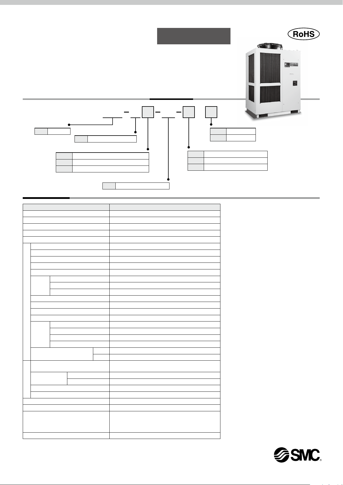
How to Order
HRS 200 A
Cooling capacity
200
20.5 kW
Nil
F
N
NPT (With Rc-NPT conversion fitting)
Specifications
Model
Cooling method Air-cooled refrigeration
Refrigerant R410A (HFC)
Refrigerant charge kg 1.65
Control method PID control
Ambient temperature/Altitude
Circulating fluid
Set temperature range
Cooling capacity
Heating capacity
Temperature stability
Pump
capacity
Minimum operating flow rate
Tank capacity L 25
Circulating fluid outlet, circulating fluid return port
Tank drain port Rc3/4 (Symbol F: G3/4, Symbol N: NPT3/4)
Circulating fluid system
Automatic
fluid fill
system
(Standard)
Fluid contact material
Power supply
Applicable earth leakage
breaker (Standard)
Rated operating current
Electrical system
Rated power consumption
Noise level (Front 1 m/Height 1 m)
Waterproof specification IPX4
Accessories
Weight (dry state) kg 214
1, 2
*
1
*
3, 7
*
4
*
5
*
Rated flow (Outlet) L/min 45 (0.45 MPa)
Maximum flow rate L/min 130
Maximum pump head m 50
Supply side pressure range
Supply side fluid temperature
Automatic fluid fill port Rc1/2 (Symbol F: G1/2, Symbol N: NPT1/2)
Overflow por t
Rated current
Sensitivity of leak current
Cooling method
A
Air-cooled refrigeration
Pipe thread type
Rc
G (With Rc-G conversion fitting)
46
3-phase 460 VAC (60 Hz)
1, 7
*
5
*
°C
°C
kW 20.5
kW 5.3
°C ±1
6
*
L/min 25
MPa 0.2 to 0.5
°C
Metal
Resin PTFE, PU, FKM, EPDM, PVC, NBR, POM, PE, NR
A 30
mA 30
A 14.2
5
*
kW(kVA)
5
*
dB(A) 75
Temperature: –5 to 45, Altitude: less than 3000 m
Tap water, 15% Ethylene glycol aqueous solution, Deionized water
Stainless steel, Copper (Heat exchanger brazing), Brass, Bronze
Allowable voltage range ±10% (No continuous voltage fluctuation)
Operation Manual (for installation/operation) 1 pc. (English),
Y-strainer (40 meshes) 25A, Barrel nipple 25A,
Anchor bolt fixing brackets 2 pcs. (including 6 M8 bolts)
Power supply
Rc1 (Symbol F: G1, Symbol N: NPT1)
Rc1 (Symbol F: G1, Symbol N: NPT1)
3-phase 460 VAC (60 Hz)
Alarm code list sticker 1 pc. (English),
46
HRS200-Am-46-mS
5 to 35
5 to 35
9.1 (11.4)
S
Option 1
Nil None
A With caster adjuster-foot
1
*
K
*1 This is a manual fluid fill port that is different from the automatic
fluid fill port. Fluid can be supplied manually into the tank without
removing the side panel. (Fluid can be supplied manually for
models without option K if the side panel is removed.)
(Pending for UL Standards)
Option 2
Nil None
W SI unit only
With fluid fill port
*1 When the ambient temperature or circulating fluid
temperature is 10°C or below, refer to "Operation at
low ambient temperature or low circulating fluid temperature" (page 14).
*2 Use fluid in condition below as the circulating fluid.
Tap water: Standard of The Japan Refrigeration And
Air Conditioning Industry Association (JRA GL-02-
1994)
15% ethylene glycol aqueous solution: Diluted with
clean water, without any additives such as antiseptics.
Deionized water: Electric conductivity 1 μS/cm or
higher (Electric resistivity 1 MΩ·cm or lower)
*3 q Ambient temperature: 32°C, w Circulating fluid:
Tap water, e Circulating fluid temperature: 20°C, r
Circulating fluid flow rate: Rated flow, t Power supply: 460 VAC
*4 q Ambient temperature: 32°C, w Circulating fluid:
Tap water, e Circulating fluid flow rate: Rated flow,
r Power supply: 460 VAC
*5 q Ambient temperature: 32°C, w Circulating fluid:
Tap water, e Circulating fluid temperature: 20°C, r
Load: Same as the cooling capacity, t Circulating
fluid flow rate: Rated flow, y Power supply: 460 VAC,
u Piping length: Shortest
*6 Fluid flow rate to maintain the cooling capacity. If the
actual flow rate is lower than this, install a bypass
piping.
*7 If the product is used at altitude of 1000 m or higher,
refer to “Operating Environment/Storage Environment” (page 13) Item 13 “* For altitude of 1000 m or
higher.”
*8 The anchor bolt fixing brackets (including 6 M8 bolts)
are used for fixing to wooden skids when packaging
the thermo-chiller. No anchor bolt is included.
8
*
HRS200 Series
18-E700
617
1020 (Dimension of anchor bolt fixing bracket)
2
715
556
851
1114
428
421
278
110
108
Overflow port Rc1
Fluid level indicator
Power cable entry (Hole 40)
(Grommet with membrane)
Tank drain port Rc3/4
(Valve stopper)
485
574
382
305
270
104
65
Handle
Circulating fluid outlet Rc1
Facility water outlet Rc1
Facility water inlet Rc1
Circulating fluid return port
Rc1
(850) (Thermo-chiller dimension)
700
1100 (Dimension of anchor bolt fixing bracket)
756 136
12 x ø12
670
43
752
50
(1035) (Thermo-chiller dimension)
1064
19
76
View B-B
HRS200 Series
Standard Type
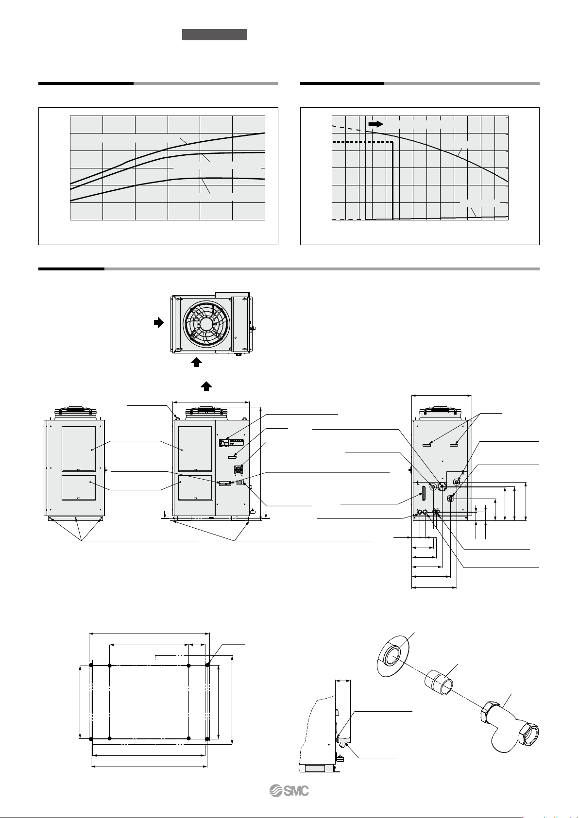
Cooling Capacity Pump Capacity
HRS200-Am-46-mS HRS200-Am-46-mS
30
25
Ambient temperature 32°C
20
15
Ambient temperature 40°C
10
Cooling capacity [kW]
5
0
5 10 15 20 25 30 35
Circulating fluid temperature [°C]
Dimensions
HRS200-A-46-S (Air-cooled 460 V type)
Ventilation air inlet
Anchor bolt fixing position
M8 bolt (Accessory)
3 pcs. attached on the opposite side
Ventilation air outlet
Eye bolt M12
(4 places)
Dustproof filter
Contact input/output
communication connector
Dustproof filter
Ambient temperature 45°C
Ventilation air inlet
A A
670
954
138
Anchor bolt fixing bracket (Accessory)
For details about the fixing position, refer to
“Anchor bolt fixing position” shown below.
8 x ø1
0.6
0.5
0.45
0.4
0.3
0.2
0.1
Circulating fluid pressure [MPa]
0
0 2010
Operation display panel
Handle
Breaker handle
Serial communication (RS-485/RS-232C) connector
1420
D-sub female receptacle
Power terminal
Automatic fluid fill port Rc1/2
Overflow port Rc1
Fluid level indicator
Signal cable entry (Hole 40)
(Grommet with membrane)
Accessory: Y-strainer mounting view
Usable flow rate range
Outlet
Return port
45
403050
60 70 80 90
100 110 120 130
Circulating fluid flow rate [L/min]
752
270
305
382
65
485
560
Tank drain port Rc3/4
(Valve stopper)
Power cable entry (Hole 40)
(Grommet with membrane)
105
Circulating fluid return port Rc1
60
50
40
30
20
Pump head [m]
10
0
Handle
Circulating fluid outlet
Rc1
Circulating fluid return port
Rc1
480
428
421
278
110
107
(954) (Thermo-chiller dimension)
1
984
View A-A
Barrel nipple 25A
130
627
(752) (Thermo-chiller dimension)
Barrel nipple (25A)
(Accessory)
Y-strainer
(Accessory)
Y-strainer
(40 mesh) 25A
Partially enlarged view A
Thermo-chiller
Standard Type
HRS200 Series
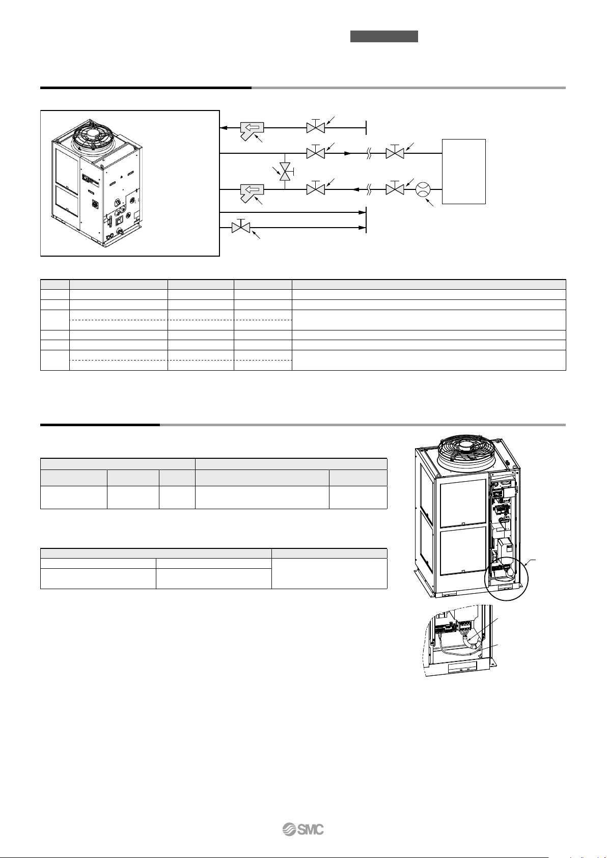
Recommended External Piping Flow
External piping circuit is recommended as shown below.
Thermo-chiller
automatic fluid
fill port
Circulating fluid
outlet
6
1
Circulating fluid
return port
Overflow port
3
Tank drain port
5
* Ensure that the overflow port is connected to the wastewater collection pit in order to avoid damage to the tank of the thermo-chiller.
1
Fluid supply
2 2
2 2
To wastewater collection pit
User’s
equipment
4
No. Description Size
1 Valve Rc1/2 — —
2 Valve Rc1 — —
3
4 Flow meter — — Prepare a flow meter with an appropriate flow range.
Valve (Part of thermo-chiller)
5
6
*1 The filter shown above cannot be directly connected to the thermo-chiller. Install it in the user’s piping system.
Y-strainer Rc1 #40 Accessory
Filter Rc1 20 μm HRS-PF005
Rc3/4 — —
Y-strainer Rc1/2 #40 —
Filter Rc1/2 20 μm —
Recommended part no.
*
Note
Install either the strainer or filter. If foreign matter with a size of 20 μm or more are likely to enter, install
1
the particle filter. For the recommended filter, refer to the optional accessory HRS-PF005 (page 9).
Install either the strainer or filter. If foreign matter with a size of 20 μm or more
are likely to enter, select and prepare a particle filter.
Cable Specifications
Power supply and signal cable should be prepared by user.
Power Cable Specifications
Rated value for thermo-chiller Power cable examples
Power supply
3-phase 460 VAC
(60 Hz)
An example of the cable specifications is when two kinds of vinyl insulated wires with a continuous allowable operating temperature
*
of 70°C at 600 V, are used at an ambient temperature of 30°C. Select the proper size of cable according to an actual condition.
Applicable breaker
rated current
30 A M5
Terminal block
thread size
Cable size
4 cores x 5.5 mm2 (4 cores x AWG10)
(Including grounding cable)
Signal Cable Specifications
Terminal block screw diameter Recommended crimped terminal
Terminal specifications Cable specifications
M3
Y-shape crimped terminal
1.25Y-3
0.75 mm
Crimped terminal on
the thermo-chiller side
2
(AWG18)
Shielded cable
R5.5-5
A
Power cable
Signal cable
2
t
r
y
u
i
o
HRS200 Series
Standard Type
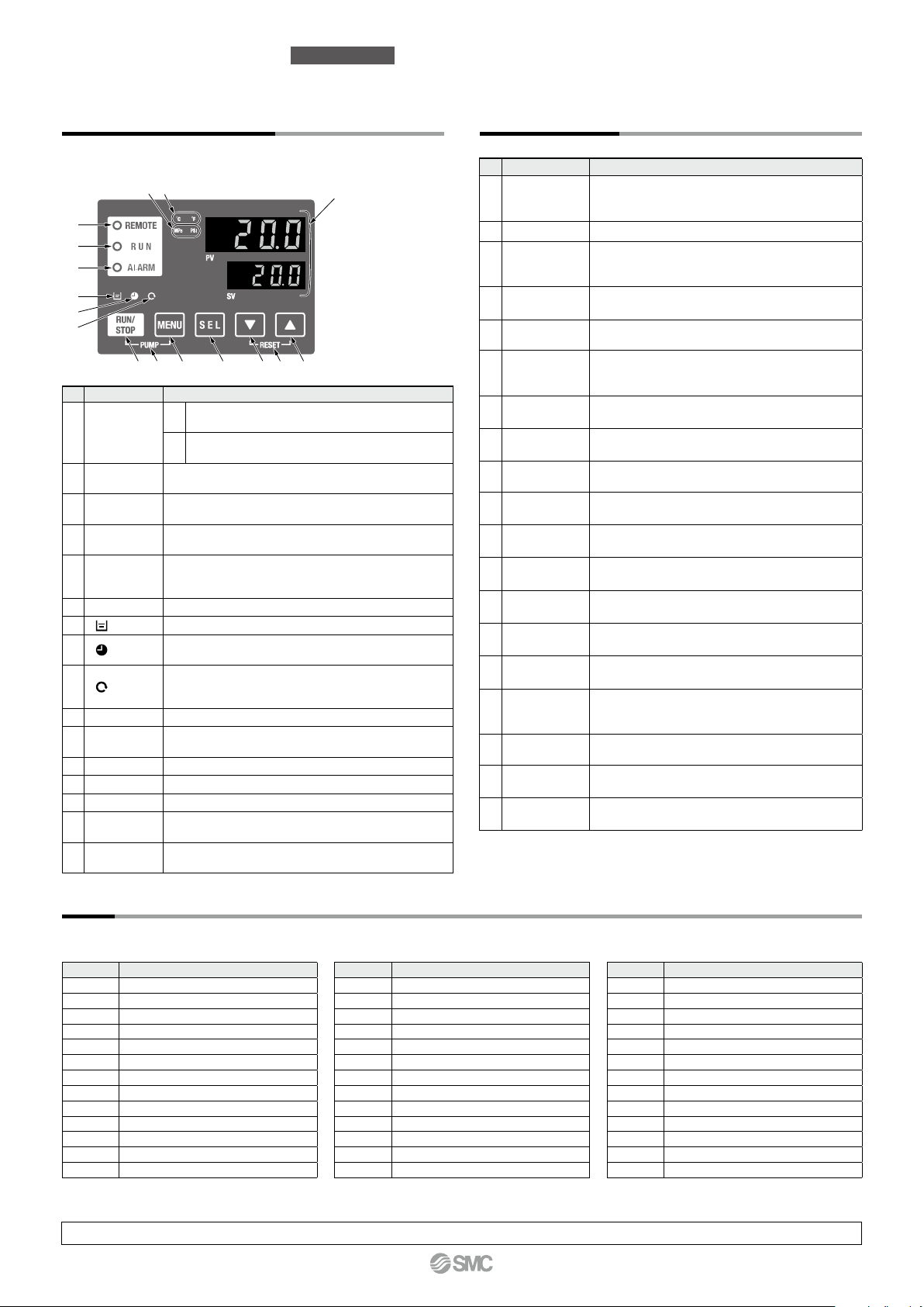
Operation Display Panel
The basic operation of this unit is controlled through the
operation display panel on the front of the product.
we
!0 !1 !2 !3 !4!5 !6
No.
Description Function
Displays the circulating fluid current discharge temperature
lamp
lamp
lamp
lamp
PV
and pressure and alarm codes and other menu items (codes).
Displays the circulating fluid discharge temperature
SV
and the set values of other menus.
Equipped with a unit conversion function. Displays the
unit of displayed temperature (default setting: °C).
Equipped with a unit conversion function. Displays the
unit of displayed pressure (default setting: MPa).
Enables remote operation (start and stop) by
communication. Lights up during remote operation.
Lights up when the product is started, and goes off when
it is stopped. Flashes during stand-by for stop or antifreezing function, or independent operation of the pump.
Flashes with buzzer when alarm occurs.
Lights up when the surface of the fluid level indicator falls below the L level.
Equipped with a timer for start and stop. Lights up
when this function is operated.
Equipped with a power failure auto-restart function, which
restarts the product automatically after stopped due to a
power failure. Lights up when this function is operated.
Makes the product start or stop.
Shifts the main menu (display screen of circulating fluid discharge temperature
and pressure) and other menus (for monitoring and entry of set values).
Press the [MENU] and [RUN/STOP] keys simultaneously. The pump starts
running independently to make the product ready for start-up (release the air).
Press the [] and [] keys simultaneously. The alarm
buzzer is stopped and the [ALARM] lamp is reset.
Digital display
(7-segment,
q
4 digits)
[°C] [°F] lamp
w
[MPa] [PSI]
e
lamp
[REMOTE]
r
lamp
[RUN]
t
[ALARM] lamp
y
[ ]
u
[ ]
i
[ ]
o
[RUN/STOP] key
!0
[MENU] key
!1
[SEL] key Changes the item in menu and enters the set value.
!2
[] key Decreases the set value.
!3
[] key Increases the set value.
!4
[PUMP] key
!5
[RESET] key
!6
q
List of Function
No.
Function Outline
Displays the current and set temperature of the
1 Main display
2
Alarm display menu
Inspection
3
monitor menu
4 Key-lock
Timer for operation
5
start/stop
Signal for the
6
completion of
preparation
7
Offset function
Reset after
8
power failure
Key click
9
sound setting
Changing
10
temp. unit
Changing
11
pressure unit
12 Data reset
Accumulation
13
time reset
Anti-freezing
14
function
Warming-up
15
function
Anti-snow
16
coverage
function
Alarm buzzer
17
sound setting
Alarm
18
customizing
19
Communication
circulating fluid, discharge pressure of the circulating
fluid. Changes the circulating fluid set temperature.
Indicates alarm number when an alarm occurs.
Product temperature, pressure and accumulated
operating time can be checked as daily inspection.
Use these for daily inspection.
Keys can be locked so that set values cannot be
changed by operator error.
Timer is used to set the operation start/stop.
A signal is output when the circulating fluid
temperature reaches the set temperature, when
using contact input/output and serial communication.
Use this function when there is a temperature offset between the
discharge temperature of the thermo-chiller and user’s equipment.
Start operation automatically after the power supply
is turned on.
Operation panel key sound can be set on/off.
Temperature unit can be changed.
Centigrade (°C) ⇔ Fahrenheit (°F)
Pressure unit can be changed.
MPa ⇔ PSI
Functions can be reset to the default settings
(settings when shipped from the factory).
Reset function when the pump, the fan or the compressor
is replaced. Reset the accumulated time here.
Circulating fluid is protected from freezing during winter
or at night. Set beforehand if there is a risk of freezing.
When circulating fluid temperature rising time at starting
needs shortening during winter or at night, set beforehand.
If there will be a possibility of the snow coverage
due to the change of the installation environment
(season, weather), set beforehand.
Alarm sound can be set to on/off.
Operation during alarm condition and threshold
values can be changed depending on the alarm type.
This function is used for contact input/output or
serial communication.
Alarm
This unit has 39 types of alarms as standard, and displays each of them by its alarm code on the PV screen with the [ALARM] lamp ([LOW LEVEL] lamp) lit
up on the operation display panel. The alarm can be read out through communication.
Code Alarm message
AL01 Low level in tank
AL02 High circulating fluid discharge temp.
AL03 Circulating fluid discharge temp. rise
AL04 Circulating fluid discharge temp. drop
AL05 High circulating fluid return temp.
AL08 Circulating fluid discharge pressure rise
AL09 Circulating fluid discharge pressure drop
AL10 High compressor intake temp.
AL11 Low compressor intake temp.
AL12 Low super heat temp.
AL13 High compressor discharge pressure
AL15
Refrigeration circuit pressure (high pressure side) drop
AL16
Refrigeration circuit pressure (low pressure side) rise
For details, refer to the Operation Manual. Please download it via our website, https://www.smcworld.com
3
Code Alarm message
AL17
Refrigeration circuit pressure (low pressure side) drop
AL18 Compressor running failure
AL19 Communication error
AL20 Memory error
AL21 DC line fuse cut
AL22
Circulating fluid discharge temp. sensor failure
AL23
Circulating fluid return temp. sensor failure
AL24 Compressor intake temp. sensor failure
AL25
Circulating fluid discharge pressure sensor failure
AL26
Compressor discharge pressure sensor failure
AL27
Compressor intake pressure sensor failure
AL28 Pump maintenance
AL29 Fan maintenance
Code Alarm message
AL30 Compressor maintenance
AL31 Contact input 1 signal detection
AL32 Contact input 2 signal detection
AL37
Compressor discharge temp. sensor failure
AL38 Compressor discharge temp. rise
AL40 Dustproof filter maintenance
AL41 Power stoppage
AL42 Compressor waiting
AL43 Fan failure
AL45 Compressor over current
AL47 Pump over current
AL50 Incorrect phase error
AL51 Phase board over current
Communication Functions
To the thermo-chiller
User’s equipment side
To the thermo-chiller User’s equipment side
To the thermo-chiller User’s equipment side
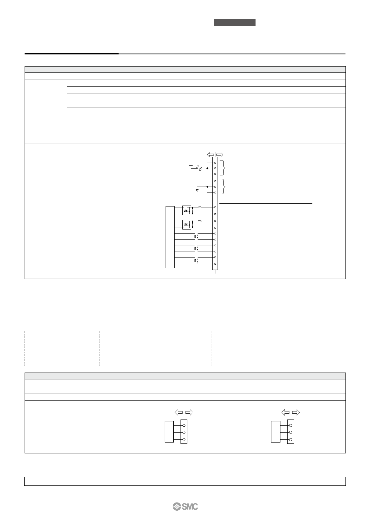
Contact Input/Output
Item Specifications
Connector type M3 terminal block
Insulation method Photocoupler
Rated input voltage 24 VDC
Input signal
Contact output
signal
Operating voltage range 21.6 to 26.4 VDC
Rated input current 5 mA TYP
Input impedance 4.7 kW
Rated load voltage 48 VAC or less/30 VDC or less
Maximum load current 500 mA AC/DC (Resistance load)
Minimum load current 5 VDC 10 mA
Output voltage 24 VDC ±10% 500 mA MAX (No inductive load)
Thermo-chiller
Standard Type
HRS200 Series
7
6
24 VDC output
(500 mA MAX)
5
15
14
24 VCOM output
13
Signal description
12
Contact input signal 2
4
11
Contact input signal 1
3
10
Contact output signal 3
2
9
Contact output signal 2
1
8
Contact output signal 1
0
2
∗
Default setting
Run/stop signal input
Alarm status signal output
Remote status signal output
Operation status signal output
1
∗
—
Circuit diagram
24 VCOM
Internal circuit
24 VDC
1 kΩ
1 kΩ
4.7 kΩ
4.7 kΩ
*1 The pin numbers and output signals can be set by user. For details, refer to the Operation Manual for communication.
*2 When using with optional accessories, depending on the accessory, the allowable current of 24 VDC devices will be reduced. Refer to the operation
manual of the optional accessories for details.
Serial Communication
The serial communication (RS-485/RS-232C) enables the following items to be written and read out.
For details, refer to the Operation Manual for communication.
Writing
Run/Stop
Circulating fluid temperature
setting (SV)
Circulating fluid present temperature
Circulating fluid discharge pressure
Status information
Alarm occurrence information
Readout
Item Specifications
Connector type D-sub 9-pin, Female connector (Mounting screw: M2.6 x 0.45)
Protocol Modicon Modbus compliant/Simple communication protocol
Standards EIA standard RS-485 EIA standard RS-232C
Circuit diagram
* The terminal resistance of RS-485 (120 W) can be switched by the operation display panel. For details, refer to the Operation Manual for communication.
Do not connect other than in the way shown above, as it can result in failure.
Please download the Operation Manual via our website, https://www.smcworld.com
circuit
Internal
1
SD+
5
SG
9
SD−
circuit
Internal
2
RD
3
SD
5
SG
4
HRS200 Series
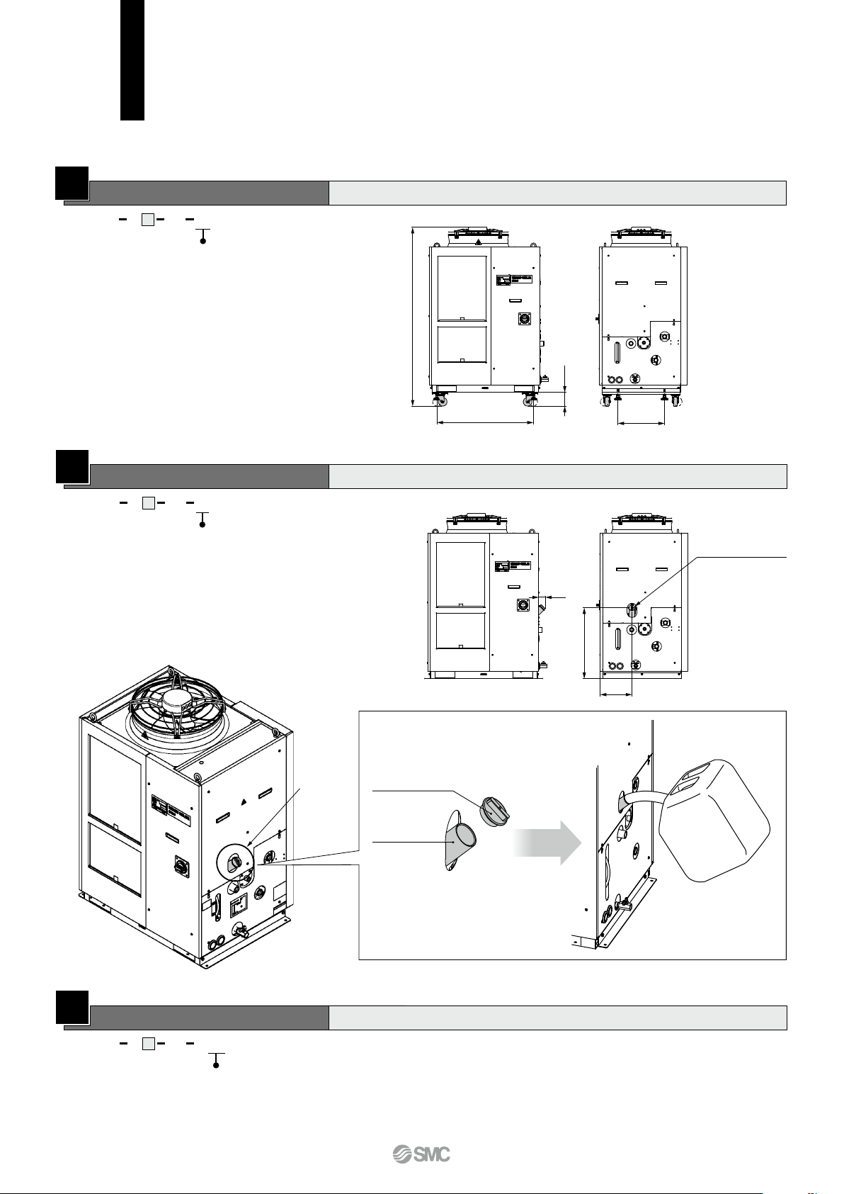
Option
[K: With fluid fill port]
Thread size: G1 1/2
(With cap)
56
609
271
Options
Option symbol
A
With Caster Adjuster-foot
HRS200 A 46 AS
With caster adjuster-foot
Unfixed casters and adjuster feet stops are mounted
* Options have to be selected when
ordering the thermo-chiller.
It is not possible to add them after
purchasing the unit.
1538
118
Option symbol
K
With Fluid Fill Port
HRS200 A 46 KS
With fluid fill port
When the automatic fluid fill in port is not used, water can be
supplied manually without removing the panel.
Fluid fill port
Cap
830
401
Option
[K: With fluid fill port]
Thread size: G1 1/2
56
609
271
(With cap)
Fluid fill port
Option symbol
W
SI Unit Only
HRS200 A 46 SW
SI unit only
The circulating fluid temperature and pressure are displayed in SI units [MPa/°C] only.
If this option is not selected, a product with a unit selection function will be provided by default.
* No change in external dimensions
5
 Loading...