

SMC Networks HRS012-W*-10-*, HRS012-A*-20-*, HRS018-A*-10-*, HRS018-W*-10-*, HRS012-W*-20-* Operation Manual
...
HRX-OM-M090
1
st
edition: Jul. 2009
Rev.M: Mar. 2013
Operation Manual
Installation・Operation
Original Instructions
Thermo chiller
Air-Cooled
refrigerated type
Water-Cooled
refrigerated type
HRS012-A∗-10-∗ HRS012-W∗-10-∗
HRS018-A∗-10-∗ HRS018-W∗-10-∗
HRS012-A∗-20-∗ HRS012-W∗-20-∗
HRS018-A∗-20-∗ HRS018-W∗-20-∗
HRS024-A∗-20-∗ HRS024-W∗-20-∗
Keep this manual available whenever necessary
© 2013 SMC CORPORATION All Rights Reserved

To the users
Thank you for purchasing SMC’s Thermo chiller (hereinafter referred to as the “product”).
For safety and long life of the product, be sure to read this operation manual (hereinafter referred to as the
“manual”) and clearly understand the contents.
• Be sure to read and follow all instructions noted with “Warning” or “Caution” in this manual.
• This manual is intended to explain the installation and operation of the product. Only people who
understand the basic operation of the product through this manual or who perform installation and
operation of or have basic knowledge about industrial machines are allowed to work on the product.
• This manual and other documents attached to the product do not constitute a contract, and will not
affect any existing agreements or commitments.
• It is strictly prohibited to copy this manual entirely or partially for the use by a third party without prior
permission from SMC.
Note: This manual is subject to possible change without priornotice.

HRX-OM-M090
Contents
HRS Series
Contents
Chapter 1 Safety Instructions .......................................................... 1-1
1.1 Before using the product ..........................................................................................1-1
1.2 Reading the Manual ...................................................................................................1-1
1.3 Hazards .......................................................................................................................1-2
1.3.1 Level of hazards.................................................................................................................. 1-2
1.3.2 Definition of “Serious injury” and “Minor injury”................................................................... 1-2
1.3.3 Types of hazard labels ........................................................................................................ 1-3
1.3.4 Locations of Hazard Labels................................................................................................. 1-4
1.4 Other Labels ............................................................................................................... 1-5
1.4.1 Product Label ...................................................................................................................... 1-5
1.5 Safety Measures.........................................................................................................1-5
1.5.1 Safety Instructions for Use .................................................................................................. 1-5
1.5.2 Personal Protective Equipment........................................................................................... 1-6
1.6 Emergency Measures ................................................................................................ 1-7
1.7 Waste disposal...........................................................................................................1-8
1.7.1 Disposal of refrigerant and compressor oil.......................................................................... 1-8
1.7.2 Disposal of product.............................................................................................................. 1-8
1.8 Material Safety Data Sheet (MSDS) ..........................................................................1-8
Chapter 2 Name and Function of Parts............................................. 2-1
2.1 Part number of product .............................................................................................2-1
2.2 Name and Function of Parts .....................................................................................2-2
2.3 Function of Parts........................................................................................................2-3
2.4 Operation display panel ............................................................................................2-4
Chapter 3 Transport and Setting Up ................................................. 3-1
3.1 Transport ....................................................................................................................3-1
3.1.1 Transportation using casters............................................................................................... 3-2
3.2 Installation .................................................................................................................. 3-3
3.2.1 Environment ........................................................................................................................ 3-4
3.2.2 Location (Required ventilation rate and facility water source) ............................................ 3-5
3.2.3 Installation and Maintenance Space ................................................................................... 3-6
3.3 Installation .................................................................................................................. 3-7
3.3.1 Mounting.............................................................................................................................. 3-7
3.3.2 Electrical wiring ................................................................................................................... 3-8
3.3.3 Preparation and wiring of power supply cable .................................................................... 3-9
3.3.4 Wiring of remote operation signal input..............................................................................3-11
3.3.5 Wiring of operation signal output and alarm signal output................................................ 3-13
3.3.6 RS-485 Communication wiring.......................................................................................... 3-14
3.3.7 RS-232C Communication wiring ....................................................................................... 3-15
3.4 Piping ........................................................................................................................ 3-16

HRX-OM-M090
Contents
HRS Series
3.5 Fill of circulating fluid..............................................................................................3-18
3.6 Option J Piping of【Automatic fluid filling】 ....................................................... 3-19
3.7 Wiring of external switch ........................................................................................3-20
3.7.1 Reading of the External switch .......................................................................................... 3-21
3.7.2 Wiring................................................................................................................................. 3-22
3.7.3 Setting items ...................................................................................................................... 3-23
Chapter 4 Starting the Product.......................................................... 4-1
4.1 Before Starting........................................................................................................... 4-1
4.2 Preparation for Start ..................................................................................................4-2
4.2.1 Power supply .......................................................................................................................4-2
4.2.2 Setting of circulating fluid temperature ................................................................................4-2
4.3 Preparation of circulating fluid.................................................................................4-3
4.4 Starting and Stopping................................................................................................4-6
4.4.1 Starting the product..............................................................................................................4-6
4.4.2 Stopping the product............................................................................................................4-7
4.5 Check items after starting.........................................................................................4-8
4.6 Adjustment of Circulating Fluid ...............................................................................4-8
Chapter 5 Display and setting of various functions........................ 5-1
5.1 Function...................................................................................................................... 5-2
5.1.1 Key operations.....................................................................................................................5-2
5.1.2 List of parameters ................................................................................................................ 5-4
5.2 Main screen ................................................................................................................5-7
5.2.1 Main screen ......................................................................................................................... 5-7
5.2.2 Display on the main screen .................................................................................................5-7
5.3 Alarm display menu................................................................................................... 5-8
5.3.1 Alarm display menu .............................................................................................................5-8
5.3.2 Content of display of alarm display menu............................................................................ 5-8
5.4 Inspection monitor menu .......................................................................................... 5-9
5.4.1 Inspection monitor menu .....................................................................................................5-9
5.4.2 Checking of the Inspection monitor menu ...........................................................................5-9
5.5 Key-lock.................................................................................................................... 5-13
5.5.1 Key-lock ............................................................................................................................. 5-13
5.5.2 Key-lock setting / checking ................................................................................................5-14
5.6 Run timer, stop timer function................................................................................ 5-15
5.6.1 Run timer and stop timer function...................................................................................... 5-15
5.6.2 Setting and checking of Run timer and stop timer function...............................................5-17
5.7 Signal for completion of preparation (TEMP READY) ..........................................5-19
5.7.1 Signal for completion of preparation (TEMP READY).......................................................5-19
5.7.2 Signal for completion of preparation (TEMP READY) setting / checking.......................... 5-20
5.8 Offset function .........................................................................................................5-22

HRX-OM-M090
Contents
HRS Series
5.8.1 Offset function ................................................................................................................... 5-22
5.8.2 Offset function setting and checking ................................................................................. 5-24
5.9 Function to recover from power failure .................................................................5-26
5.9.1 Function to recover from power failure.............................................................................. 5-26
5.9.2 Function to recover from power failure setting and checking........................................... 5-27
5.10 Anti-freezing function..............................................................................................5-28
5.10.1 Anti-freezing function......................................................................................................... 5-28
5.10.2 Anti-freezing function setting and checking....................................................................... 5-29
5.11 Key click sound setting...........................................................................................5-30
5.11.1 Key click sound setting...................................................................................................... 5-30
5.11.2 Key click sound setting and checking ............................................................................... 5-30
5.12 Temperature unit switching ....................................................................................5-31
5.12.1 Temperature unit switching ............................................................................................... 5-31
5.12.2 Temperature unit switching setting and checking............................................................. 5-31
5.13 Pressure unit switching ..........................................................................................5-32
5.13.1 Pressure unit switching ..................................................................................................... 5-32
5.13.2 Pressure unit switching setting and checking .................................................................. 5-32
5.14 Alarm buzzer sound setting....................................................................................5-33
5.14.1 Alarm buzzer sound setting............................................................................................... 5-33
5.14.2 Alarm buzzer sound setting and checking........................................................................ 5-33
5.15 Alarm customize function ....................................................................................... 5-34
5.15.1 Alarm customize function .................................................................................................. 5-34
5.15.2 Alarm customize function setting and checking ................................................................ 5-36
5.15.3 Setting of temperature alarm monitoring method and alarm generation timing................ 5-49
5.16 Data reset function...................................................................................................5-51
5.16.1 Data reset function ............................................................................................................ 5-51
5.16.2 Method of resetting data reset function............................................................................. 5-51
5.17 Accumulated time reset function ...........................................................................5-52
5.17.1 Accumulated time reset function ....................................................................................... 5-52
5.17.2 Method of resetting accumulated time reset function ....................................................... 5-52
5.18 Communication function......................................................................................... 5-54
5.18.1 Communication function.................................................................................................... 5-54
5.18.2 Communication function setting and checking.................................................................. 5-54
5.19 Option J [Automatic fluid filling] ............................................................................5-71
5.19.1 Option J [Automatic fluid filling] ......................................................................................... 5-71
5.20 Option [Drain pan set] .............................................................................................5-72
5.20.1 Option [Drain pan set] ....................................................................................................... 5-72
5.20.2 Option [Drain pan set] setting and checking ..................................................................... 5-73
5.21 Option [Electric resistivity sensor set] ..................................................................5-74
5.21.1 Option [Electric resistivity sensor set] ............................................................................... 5-74

HRX-OM-M090
Contents
HRS Series
5.21.2 Option [Electric resistivity sensor set] setting and checking..............................................5-75
Chapter 6 Alarm indication and trouble shooting ........................... 6-1
6.1 Alarm Display............................................................................................................. 6-1
6.2 Alarm buzzer stop...................................................................................................... 6-3
6.3 Troubleshooting.........................................................................................................6-4
6.4 Other Errors................................................................................................................6-6
Chapter 7 Control, Inspection and Cleaning.................................... 7-1
7.1 Control of Circulating Fluid Quality ......................................................................... 7-1
7.2 Inspection and Cleaning ...........................................................................................7-2
7.2.1 Daily check ..........................................................................................................................7-2
7.2.2 Monthly check......................................................................................................................7-3
7.2.3 Inspection every 3 months................................................................................................... 7-4
7.2.4 Inspection every 6 months................................................................................................... 7-4
7.2.5 Inspection for winter season................................................................................................ 7-5
7.3 Consumables .............................................................................................................7-5
7.4 Stop for a Long Time ................................................................................................. 7-6
7.4.1 Discharge of the circulating fluid and facility water.............................................................. 7-6
Chapter 8 Documents......................................................................... 8-1
8.1 Specifications List .....................................................................................................8-1
8.1.1 Product specification............................................................................................................8-1
8.1.2 Communication specifications .............................................................................................8-3
8.2 Outline dimensions....................................................................................................8-4
8.3 Flow Chart ..................................................................................................................8-5
8.3.1 HRS012-A∗-∗0, HRS018-A∗-∗0, HRS024-A∗-20............................................................... 8-5
8.3.2 HRS012-W∗-∗0, HRS018-W∗-∗0, HRS024-W∗-20............................................................ 8-5
8.4 Cooling capacity ........................................................................................................8-6
8.4.1 HRS012-∗∗-10-(BJM) ..........................................................................................................8-6
8.4.2 HRS018-∗∗-10-(BJM) ..........................................................................................................8-6
8.4.3 HRS012-∗∗-20-(BJMT) ........................................................................................................8-7
8.4.4 HRS018-∗∗-20-(BJMT) ........................................................................................................8-7
8.4.5 HRS024-∗∗-20-(BJMT) ........................................................................................................8-7
8.4.6 Option G [High temperature type]........................................................................................ 8-8
8.5 Heating capacity ........................................................................................................8-9
8.5.1 HRS012-∗∗-10,HRS018-∗∗-10 ............................................................................................8-9
8.5.2 HRS012-∗∗-20,HRS018-∗∗-20, HRS024-∗∗-20................................................................... 8-9
8.6 Pump capacity..........................................................................................................8-10
8.6.1 HRS012-∗∗-10-(BJM), HRS018-∗∗-10-(BJM)....................................................................8-10
8.6.2 HRS012-∗∗-20-(BGJM), HRS018-∗∗-20-(BGJM), HRS024-∗∗-20-(BGJM)....................... 8-10
8.6.3 Option:-T............................................................................................................................ 8-11
8.6.4 Option:-MT......................................................................................................................... 8-11

HRX-OM-M090
Contents
HRS Series
8.7 Required facility water flow (for water-cooled type)............................................. 8-12
8.8 Compliance...............................................................................................................8-13
8.9 Sample DoC..............................................................................................................8-14
8.10 Daily Check Sheet....................................................................................................8-15
Chapter 9 Product Warranty .............................................................. 9-1

HRX-OM-M090
Contents
HRS Series
HRX-OM-M090
Chapter 1 Safety Instructions
HRS Series 1.1 Before using the product
1-1
Chapter 1 Safety Instructions
1.1 Before using the product
z
This chapter is intended to specifically describe the safety related issues
for handling the product. Read this before handling the product.
z
The product is a cooling device using circulating fluid. SMC does not take
any responsibility for any problems that may arise from using the product
for other purposes.
z
This product is for indoor use only and not to be used outdoors.
z
This product is not designed for a clean room. It generates dust from the
internal components such as pump and fan motor.
z
The product is operated at high voltage and contains components which
become hot and rotate. If a component needs to be replaced or repaired,
contact a specialized vendor for parts and service.
z
All personnel who work with or around the product should read and
understand the safety related information in this manual carefully before
starting work.
z
The safety manager is responsible for strictly observing safety standards,
but responsibility in respect to safety standards during daily work resides
with each individual operator and maintainance personnel.
z
This manual must be kept available to operators whenever necessary.
1.2 Reading the Manual
This manual contains symbols to help identify important actions when
installing, operating or maintaining the product.
Before using the product be sure to read and understand all the
important actions highlighted in this manual.
This sign indicates actions that must be followed.
This sign indicates prohibited actions.

HRX-OM-M090
Chapter 1 Safety Instructions
1.3 Hazards HRS Series
1-2
1.3 Hazards
1.3.1 Level of hazards
The instructions given in this manual aim to assure the safe and correct
operation of the product, and to prevent injury of operators or damage to the
product. These instructions are grouped into three categories, Danger,
Warning and Caution, which indicate the level of hazard, damage and also
the degree of emergency. All safety critical information should be carefully
observed at all times.
“DANGER”, “WARNING” and “CAUTION” signs are in order according to
severity (DANGER> WARNING> CAUTION).
1.3.2 Definition of “Serious injury” and “Minor injury”
“Serious injury”
This term describes injuries that result in after effects including loss of
eyesight, burns, electrical shock, fracture, poisoning, etc. and requires
long-term treatment or hospitalization.
“Minor injury”
This term describes injuries that do not need long-term treatment or
hospitalization. (Others excluded from serious injury.)
“DANGER”: Hazard that WILL cause serious personal injury or death during
operation.
“WARNING”: Hazard that MAY cause serious personal injury or death during
operation.
“CAUTION”: Hazard that MAY cause minor personal injury.
“CAUTION without exclamation symbol”: Hazard that MAY cause damage or failure
of the product, facility, devices, ect.
HRX-OM-M090
Chapter 1 Safety Instructions
HRS Series 1.3 Hazards
1-3
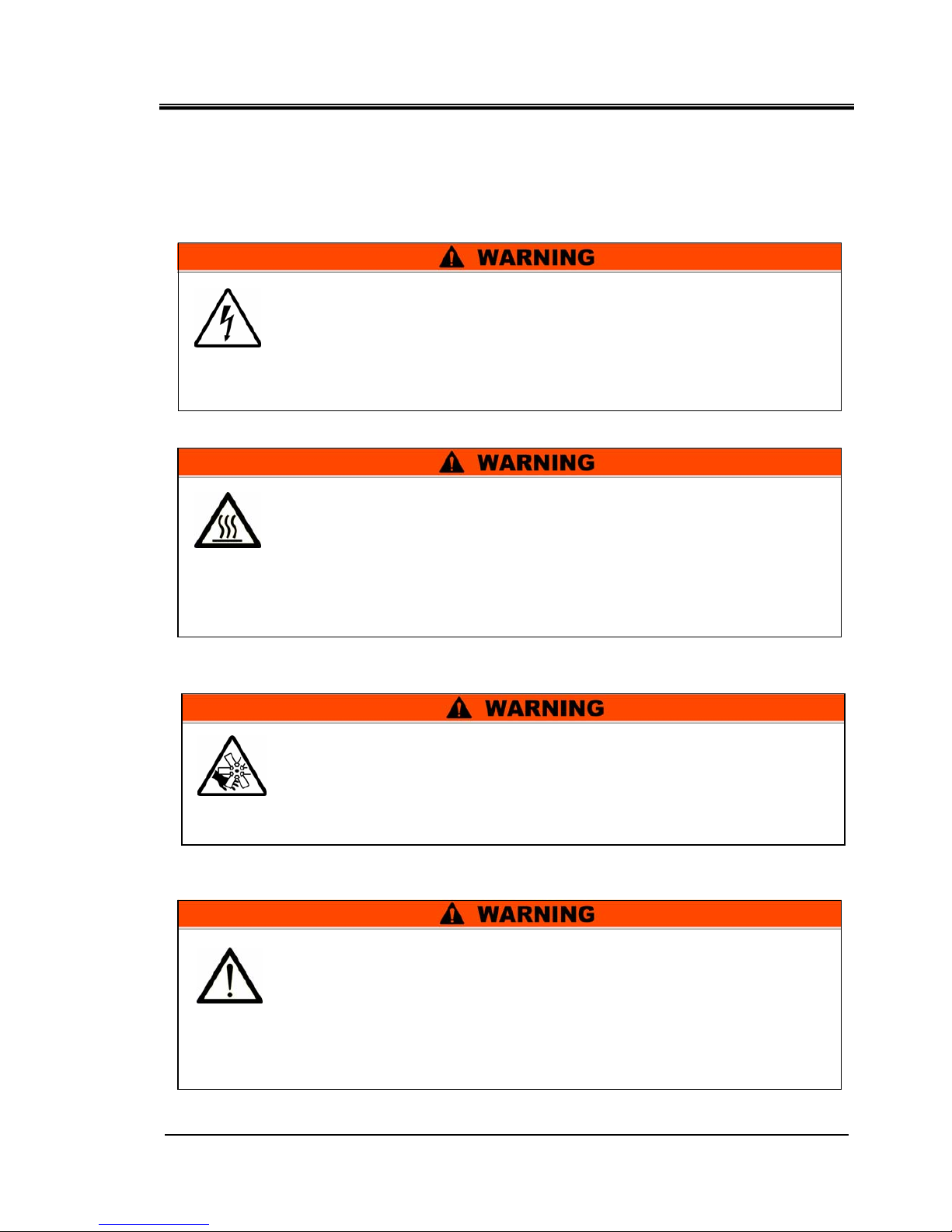
1.3.3 Types of hazard labels
The product has various potential hazards and they are marked with
warning labels. Be sure to read this section before starting any work on the
product.
Warning related to electricity
Warning related to high temperatures
Warning related to rotating objects
Warning related to other general dangers
This symbol stands for a possible risk of electric shock.
The product is operated at high voltage and contains uncovered live
terminals inside.
z DO NOT operate the product without cover panels fitted.
DO NOT work inside this product unless you have been trained to do
so.
This symbol stands for general danger.
Hazards Inside
Hot Surfaces Inside – See Hot Surface symbol
Rotating Fan Inside – See Rotating Fan symbol (For air-cooled type)
Pressurized Sytem Inside – The product contains pressurised fluid
systems.
z DO NOT operate the product without cover panels fitted.
This symbol stands for a possible risk of hot surface and burns.
The product has surfaces that can reach high temperatures during
operation. Even after the power is turned off, there can still be residual
heat in the product.
z DO NOT operate the product without cover panels fitted.
z DO NOT start working inside the product until the temperature has
decreased sufficiently.
This symbol stands for a possible risk of cutting fingers or hand, or
entanglement by rotating fan (For air-cooled type).
The product contains a cooling fan that rotates during operation of the
product.
The fan can start and stop intermittently and without warning.
z DO NOT operate the product without cover panels fitted.
HRX-OM-M090
Chapter 1 Safety Instructions
1.3 Hazards HRS Series
1-4
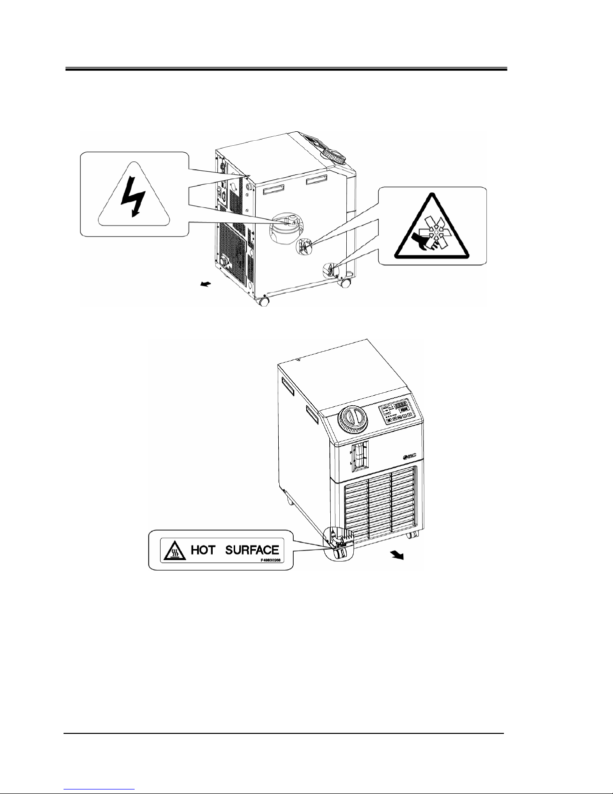
1.3.4 Locations of Hazard Labels
There are various warning labels on the product to show the potential
hazards.
Fig. 1-1 Warning label position
∗ For air-cooled type
Fig.
1-2 Warning label position
Rear
Front
HRX-OM-M090
Chapter 1 Safety Instructions
HRS Series 1.4 Other Labels
1-5
1.4 Other Labels
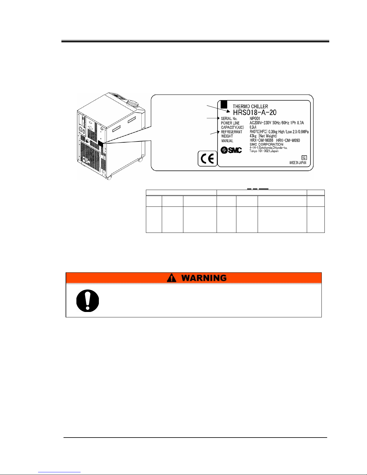
1.4.1 Product Label
Information about the product, such as Serial No. and Model No. can be
found on the model label. This information is needed when contacting an
SMC sales distributor.
How to see the manufacturing code R
O 001 (January 2013)
O O 001
Year Symbol Remarks Month Symbol Remarks
Serial
no.
2013 R
1 O
2014 S 2 P
2015 T 3 Q
↓ ↓
Repeated
from
A to Z in
alphabetical
order
↓ ↓
Repeated from
O to Z in alphabetical
order, with O for
January and Z for
December
-
Fig. 1-3 Position of product label
1.5 Safety Measures
1.5.1 Safety Instructions for Use
z
Read and understand this manual carefully before using the product.
z
Before starting maintenance of the product, be sure to lock out and tag out the
breaker of the user's power supply.
z
If operating the product during maintenance, be sure to inform all workers nearby.
z
Use only the correct tools and procedure when installing or maintaning the product.
z
Use personal protective equipment where specified (“1.5.2 Personal Protective
Equipment”)
z
Check all parts and screws are fitted correctly and securely after maintenance.
z
Avoid working in a drunken or sick condition, which might cause an accident.
z
Do not remove the panels except for the cases permitted in this manual.
z
Do not remove the panels during operation.
Follow the instructions below when using the product. Failure to
follow the instructions may cause an accident and injury.
∗
(It is an example of model "HRS018-A-20".)
Model Number
Serial Number
(SERIAL No.)
The type and quantity
of refrigerant
(REFRIGERANT)

HRX-OM-M090
Chapter 1 Safety Instructions
1.5 Safety Measures HRS Series
1-6
1.5.2 Personal Protective Equipment
This manual specifies personal protective equipment for each work.
Transport, Installing and Uninstalling
Handling of circulating fluid
Operation
Always use safety shoes, gloves and head protection when
transporting, installing or uninstalling the product.
Always use safety shoes, gloves, mask, apron and eye protection
when handling the circulating fluid.
Always use safety shoes and gloves when operating the product.
HRX-OM-M090
Chapter 1 Safety Instructions
HRS Series 1.6 Emergency Measures
1-7
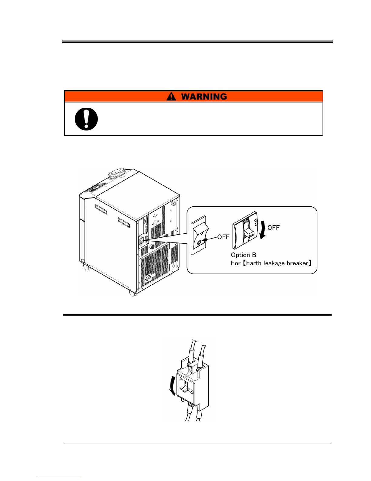
1.6 Emergency Measures
When emergency conditions such as natural disaster, fire and earthquake,
or injury occurs, turn off the power supply switch. The switch is located at
the front of the product.
1. Turn off the power supply switch at the back of the product to stop the operation of the
thermo-chiller.
Fig. 1-4 Location of the switch for the power supply
2. Be sure to shut off the breaker of the facility power supply (the power supply of the
user’s machine).
Fig. 1-5 Shut off of facility power supply
Even when the power supply swich is turned off, some of the internal
circuits are still energized, unless the user’s power supply is shut off.
Be sure to shut off the breaker of the user’s power supply.
HRX-OM-M090
Chapter 1 Safety Instructions
1.7 Waste disposal HRS Series
1-8
1.7 Waste disposal
1.7.1 Disposal of refrigerant and compressor oil
The product uses hydrofluorocarbon type refrigerant (HFC) and compressor
oil. Comply with the laws and regulations in each country for the disposal of
refrigerant and compressor oil. The type and quantity of refrigerant is
described on the 1.4.1 Product Label.
If these fluids need to be recovered, read and understand the instructions
below carefully. If there is any unclear point, contact an SMC's sales
distributor.
1.7.2 Disposal of product
The disposal of the product must be handled by a specialized industrial
waste disposal agency in accordance with local laws and regulations.
1.8 Material Safety Data Sheet (MSDS)
If the material safety data sheets of chemicals used in this product are
needed, contact an SMC's sales distributor.
Any chemicals used by the user must be accompanied by an MSDS.
Comply with the laws and regulations in each country for the disposal
of refrigerant and compressor oil.
The release of refrigerant in to the atmosphere is banned by law.
Recover it with specific equipment and dispose of it correctly.
Only people who have sufficient knowledge and experience about the
product and its accessories are allowed to recover the refrigerant
and compressor oil.
Only maintenance personnel or qualified people are allowed to open
the cover panels of the product.
Do not mix the compressor oil with domestic waste for disposal. Also,
the disposal of the waste must only be conducted by specific
facilities that are permitted for that purpose.
HRX-OM-M090
Chapter 2 Name and Function of Parts
HRS Series 2.1 Part number of product
2-1
Chapter 2 Name and Function of Parts
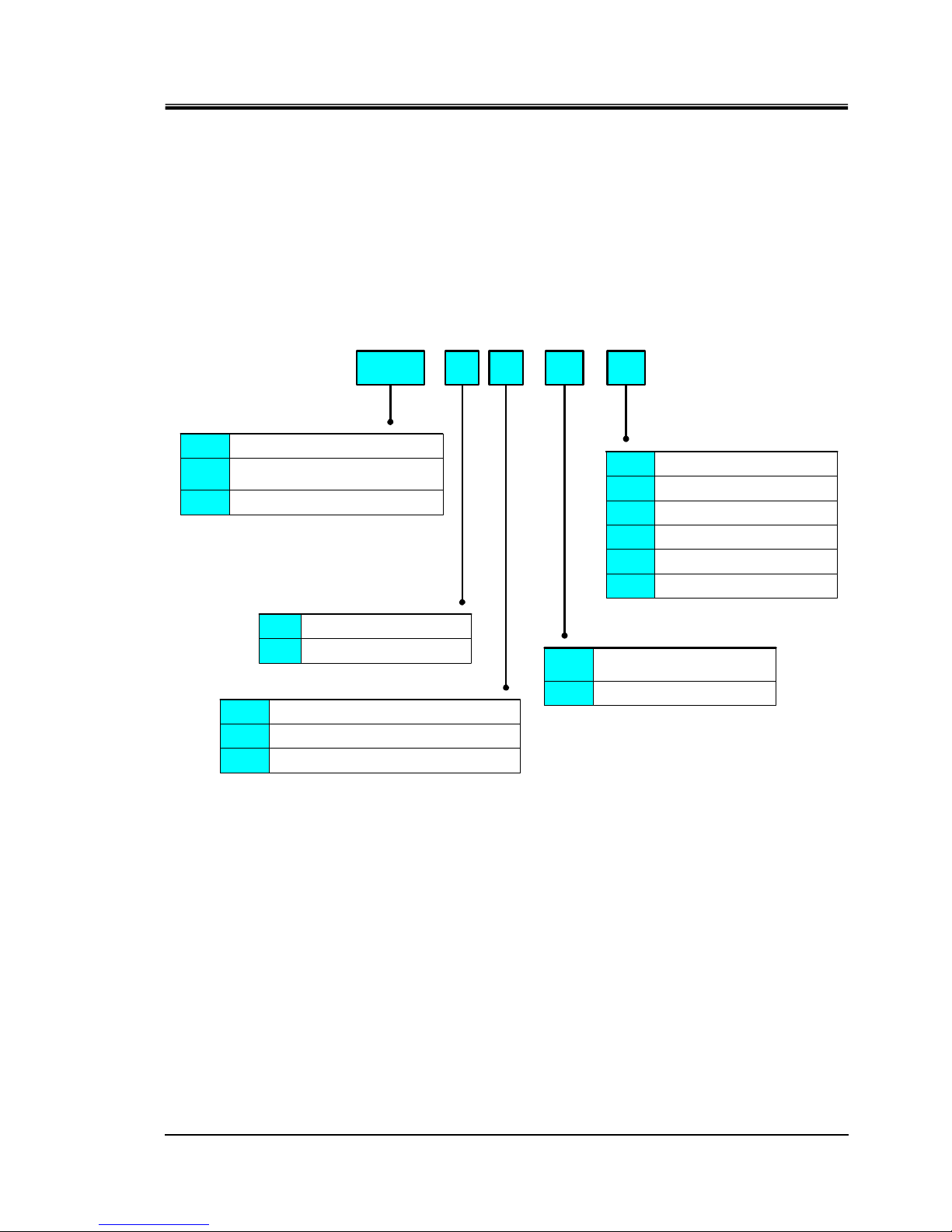
2.1 Part number of product
The product can be ordered with the part number configured as shown
below.
The product needs to be handled in different ways depending on the part
number. Refer to “1.4.1 Product Label” and check the part number of the
product.
Fig. 2-1 Part number of product
10A012
012
HRS
①Cooling capacity
②Cooling method
③Piping thread type
④Power supply
-
Null
F
N
-
Rc
G (PT-G conversion fitting is included)
NPT (PT-NPTconversion fitting is included)
A Air-cooled refrigerator type
W Water-cooled refrigerator type
20 1-phase AC200~230V(50/60Hz)
10
1-phase AC100V(50Hz)
1-phase AC100~115V(60Hz)
018
024
∗1 ④Power supply:-10(100V Type)
∗2 ④Power supply:-20(200V Type)
∗3 ④Power supply:Only -20(200V Type)can be chosen.
∗4 ②Cooling method:-A(Air-cooled refrigerator type),
④Power supply:Only -20(200V Type)can be chosen.
1100W/1300W (50/60Hz)
1500W/1700W (50/60Hz)(∗1)
1700W/1900W (50/60Hz)(∗2)
2100W/2400W (50/60Hz)(∗3)
-
⑤Option
Null None
J Automatic water-supply
M Pure water piping
T High-pressure pump mounted
B Earth leakage breaker
G High temperature type(∗4)
HRX-OM-M090
Chapter 2 Name and Function of Parts
2.2 Name and Function of Parts HRS Series
2-2
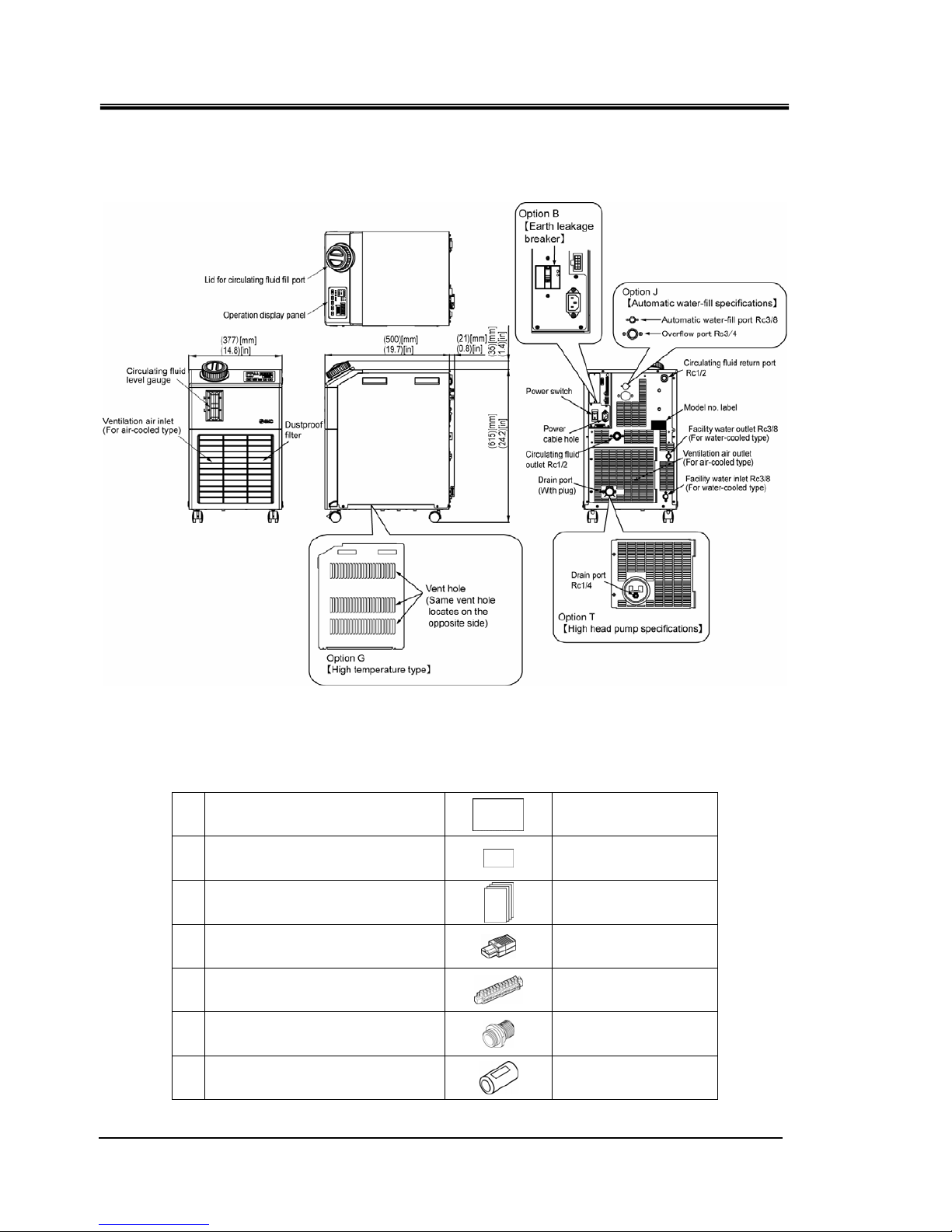
2.2 Name and Function of Parts
Fig. 2-2 Names of each part
Table 2-1 Accessories list
1
Quick manual
1pc.
(with a clear cover)
2
Alarm code list label
1pc.
3
Operation Manual
2pcs.
(Jpn: 1pc., Eng:1pc.)
4
Power supply connector
1pc.
5
Sequence I/O command signal
connector
1pc.
6
Fitting (for drain port)*
1pc.
7
Ferrite core (for communication)
1pc.
∗ Not included when option [High head pump] is selected.

HRX-OM-M090
Chapter 2 Name and Function of Parts
HRS Series 2.3 Function of Parts
2-3
2.3 Function of Parts
The function of parts is as follows.
Table 2-2 Function of parts
Name Function
Operation display panel
Runs and stops the product and performs settings such as the circulating
fluid temperature.
For details, refer to ’’2.4 Operation display panel’’.
Power supply switch
Shuts off the power supply to the internal eqipment of product.
Circuit protector 10A
Model label
Shows the part number of the product.
For details, refer to ‘’1.4.1 Product Label’’.
Circulating fluid outlet port The circulating fluid flows out from the outlet port.
Circulating fluid return port The circulating fluid returns to the return port.
Drain port
This drain port to drain the circulating fluid out of the tank.
(The plug is connected to standard pump type at the time of shipment. The
ball valve is installed in the high pump head type.)
Facility water inlet
(For water-cooled type)
A facility water inlet to which the facility water is fed through piping.
The pressure of facility water should be in a range of 0.3 to 0.5MPa.
Facility water outlet
(For water-cooled type)
A facility water outlet from which the facility water returns to the user’s
machine through piping.
Automatic water-fill port
(When automatic fluid filling
[Option] is selected.)
Piping to the automatic fluid filling port enables easy supply of the circulating
fluid through the built-in solenoid valve.The supply pressure should be in a
range of 0.2 to 0.5MPa.
Overflow port
(When automatic fluid filling
[Option] is selected.)
This is necessary when automatic fluid filling function.Discharge excess
circulating fluid when the fluid level in the tank rises.
HRX-OM-M090
Chapter 2 Name and Function of Parts
2.4 Operation display panel HRS Series
2-4
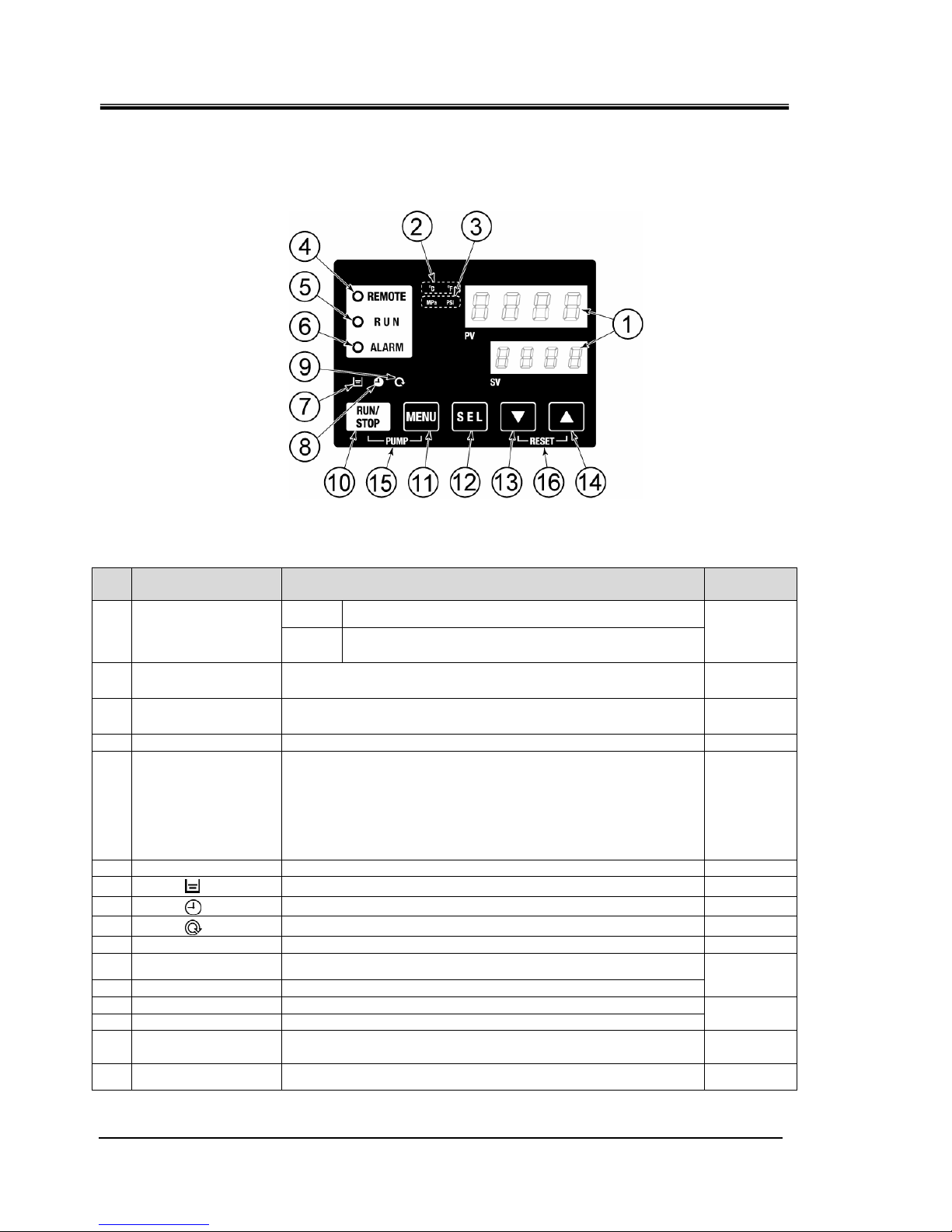
2.4 Operation display panel
The operation panel on the front of the product controls the basic operation
of the product.
Fig. 2-3 Operation display panel
Table 2-3 Operation display panel
No Description Function
Reference
page
PV
Displays the temperature and pressure of the circulating
fluid and alarm codes.
①
Digital display
(7 segment,
4 digits)
SV
Displays the set temperature of the circulating fluid and
the set values of other menus.
5.2
② [ oC oF ] lamp Displays the unit of display temperature (℃ or oF). 5.12
③ [MPa PSI] lamp Displays the unit of display pressure (MPa or PSI). 5.13
④ [REMOTE] lamp Lights up during remote operation by communication. 5.18
⑤ [RUN] lamp
・Lights up when the product is started and in operation. Goes off
when the product is stopped.
・Flashes during stand-by for stop (Interval 0.5 seconds).
・Flashes during independent operation of the pump (Interval
0.3 seconds).
・Flashes during anti-freezing function (At standby: Interval 2
seconds, At operation: Interval 0.3 seconds).
4.4
⑥ [ALARM] lamp Flashes with buzzer when alarm occurs (Interval 0.3 seconds). 5.3
⑦
[ ] lamp Lights up when the tank level indicator falls below the LOW level. 4.3
⑧
[ ] lamp Lights up while the run timer or stop timer function is working. 5.6
⑨
[ ] lamp
Lights up when the product is in automatic operation.
5.9
⑩ [RUN/STOP] key
Makes the product start or stop.
4.4
⑪ [MENU] key
Shifts the main menu (display screen of temperature) the other
menu (entry of set values and monitor screen).
⑫ [SEL] key
Changes the item in menu and enters the set value.
5.1
⑬ [▼] key
Decreases the set value.
⑭ [▲] key
Increases the set value.
-
⑮ [PUMP] key
When the [MENU] and [RUN/STOP] keys are held down
simultaneously, the pump starts running independently.
4.3
⑯ [RESET] key
Keep the [▼] and [▲] keys pressed down simultaneously. This will
stop the alarm buzzer and reset the [ALARM] lamp.
6.3
HRX-OM-M090
Chapter 3 Transport and Setting Up
HRS Series 3.1 Transport
3-1
Chapter 3 Transport and Setting Up
3.1 Transport
The product is heavy and has potential danger at transport. Also, to prevent
damage and breakage of the product, be sure to follow these instructions for
transport.
Only persons who have sufficient knowledge and experience about the
product and system are allowed to transport and set up the
product.
Especially pay attention to personal safety.
Never lay the product on its side.
The compressor oil will leak in to the refrigerant piping, which may
cause early failure of the compressor.
Drain the residual fluid from the piping as much as possible to prevent
any spillage.
HRX-OM-M090
Chapter 3 Transport and Setting Up
3.1 Transport HRS Series
3-2
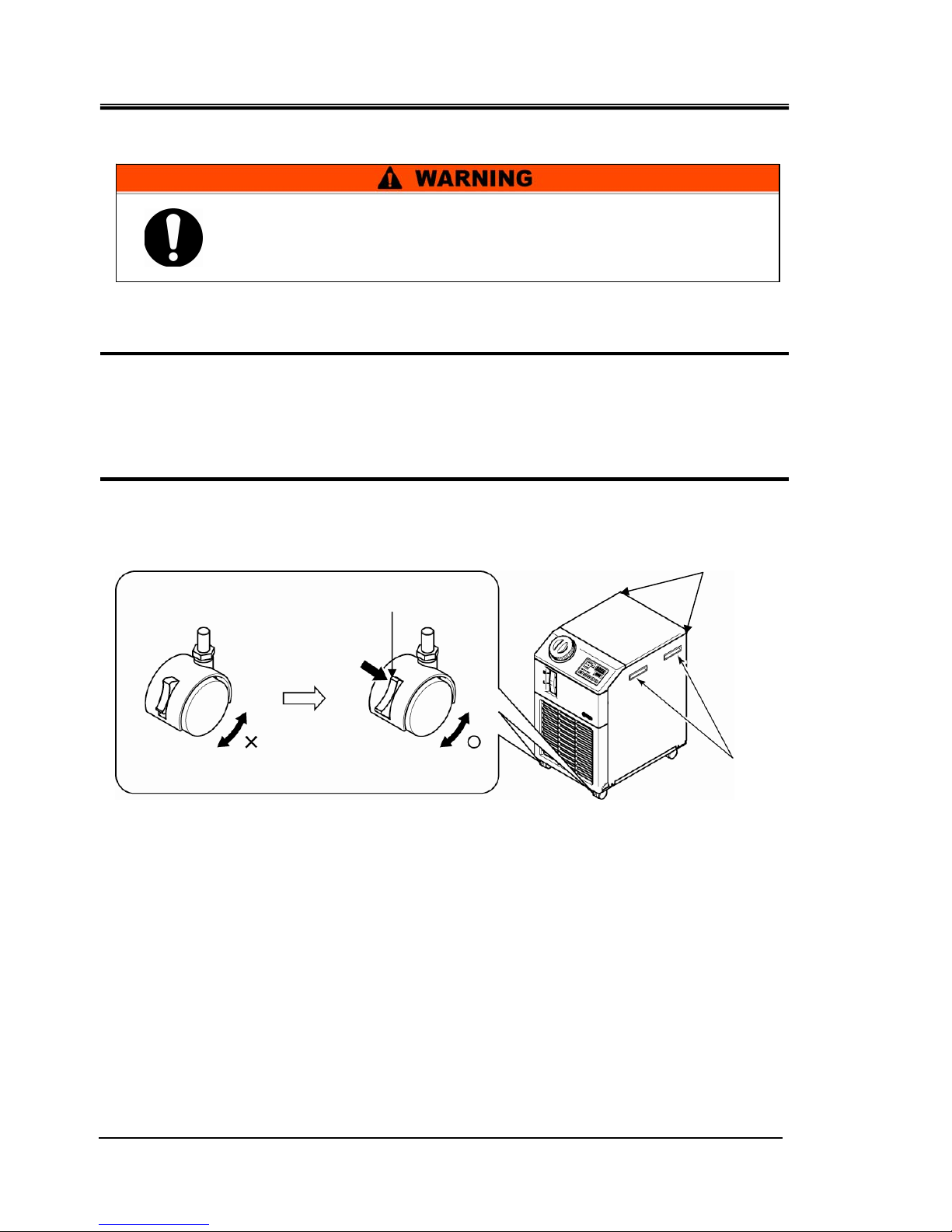
3.1.1 Transportation using casters
1. Release the lock levers of the front casters.
2. Push the handles on the right/left panel or the corner of the product to move the product
to the destination.
Do not hold the product by the cap to move it. This will apply excess force to the piping of
internal parts which may lead to malfunctions such as fluid leakage.
3. To push the front or rear panel, push it by the corner. Pushing by the center of the panel
may deform the shape.Care should be taken.
Fig. 3-1 Transportation using casters
Handle
Unlocking
Press
Corners
This product is heavy.
Care should be taken when the product is transported on a slope.
HRX-OM-M090
Chapter 3 Transport and Setting Up
HRS Series 3.2 Installation
3-3
3.2 Installation
Keep the product horizontal to a rigid and flat floor which can resist
the weight of the product, and take measures to prevent the
product from tipping over. Improper installation may cause water
leakage, tipping, damage of the product or injure the operator.
Keep the ambient temperature of the product between 5 to 40
o
C.
Operation below 5
o
C may cause the compressor failure, and
operation above 40
o
C may cause the product to overheat and shut
down.
∗
The operating ambient temperature is 5 to 45deg. C for option G
[Hig
h temperature type].
Do not set up the product in places possibly exposed to leakage of
flammable gas. Should any flammable gas stay around the
product, the product may cause a fire.
Do not use the product outdoors. If the product subjected to rain or
water splash it may cause electrical shock, fire or failure.

HRX-OM-M090
Chapter 3 Transport and Setting Up
3.2 Installation HRS Series
3-4
3.2.1 Environment
The product must not be operated, installed, stored or transported in the
following conditions. Potential malfunction or damage to the product may
occur if these instructions are disregarded.
The product does not conform to any Clean room specifications. The pump
and ventilating fan inside the product generate particles.
The installer/end user is responsible for carrying out an acoustic noise risk
assessment on the equipment after installation and taking appropriate
measures as required.
z
Location that is outside.
z
Location that is exposed to water, water vapour, steam, salt water or oil.
z
Location that is exposed to dust or powder material.
z
Location that is exposed to corrosive gas, organic solvent, chemical
solution, or flammable gas (the product is not flame-proof)
z
Location where the ambient temperature is out of the following range:
In transportation and In storage 0 to 50°C
(with no water or circulating fluid in piping)
In operation 5 to 40°C (Option G [High temperature
type]:5 to 45°C)
z
Location where the ambient humidity is out of the following range or where
condensation occurs:
In transportation and storage 15 to 85%
In operation 30 to 70%
z
Location that is exposed to direct sunlight or heat radiation.
z
Location that is near heat sources and poor in ventilation.
z
Location that is subjected to abrupt changes in temperature.
z
Location that is subjected to strong electromagnetic noise (intense electric
field, intense magnetic field, or surges).
z
Location that is subjected to static electricity, or conditions where static
electricity can discharge to the product.
z
Location that is subjected to strong high frequencies raditation
(microwaves).
z
Location that is subjected to potential lightning srtike.
z
Location at altitudes of 1000m or higher (except for product storage and
transport).
z
Location where the product is affected by strong vibrations or impacts.
z
Condition that applies external force or weight causing the product to be
damaged.
z
Location without adequate space for maintenance as required.
HRX-OM-M090
Chapter 3 Transport and Setting Up
HRS Series 3.2 Installation
3-5
3.2.2 Location (Required ventilation rate and facility water source)
Installation of multiple products
Keep sufficient space between products so that the air vented from one product will not be taken
in by other products.
Installation Area Ventilation (For air-cooled type)
① Facility having a large installation area (that can vent the air naturally)
Make an air vent on a wall at a high level and another air vent on a wall at a low level, to
allow for adequate airflow.
②
Facility having a small installation area (that can not vent the air naturally)
Make a forced air exhaust vent on a wall at a high level and an air vent on a wall at a low
level.
Table 3-1 Amount of radiation and required ventilation
Required ventilation amount m3/min
Model
Heat
Radiated
kW
Differential temp. of 3 oC
between inside and outside
of installation area
Differential temp. of 6 oC
between inside and outside
of installation area
HRS012-A∗-∗
Approx. 2
40 20
HRS018-A∗-∗
Approx. 4
70 40
HRS024-A∗-20
Approx. 5
90 50
Facility water source to be prepared (For water-cooled type)
Table 3-2 Facility water source to be prepared
Required facility water rate
l/min
Facility water temprature
Model
Heat
Radiated
kW
Facility water temp.
range
o
C
25℃ 32℃ 40℃
HRS012-W-20 Approx. 2
8 12 20
HRS018-W-20 Approx. 4
12 15 23
HRS024-W-20 Approx. 5
5to40
(Rating 25)
14 17 25
Do not install in a location which can be subjected to any of the
conditions in 3.2.1 Environment.
The product radiates heat from the air vent of the cooling fan.
If the product is operated with insufficient air ventilation the internal
temperature can exceed 40
oC∗
, which can cause an overload or affect
the performance and life of the product. To prevent this ensure that
suitable ventilation is available (see below).
∗ (Option G [High temperature type]:45°C)
The water-refrigerated thermo-cooler discharges heat by using facility
water. Therefore, it is necessary to supply facility water from the
source listed in the following table.
HRX-OM-M090
Chapter 3 Transport and Setting Up
3.2 Installation HRS Series
3-6
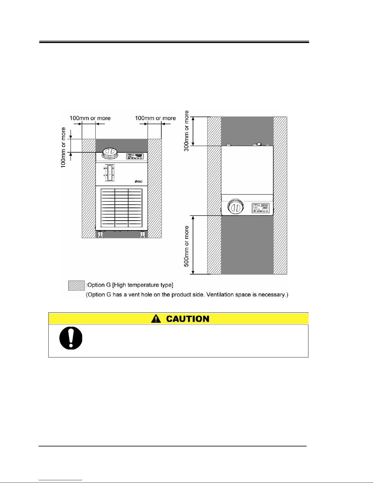
3.2.3 Installation and Maintenance Space
It is recommended to keep the space around the product shown in
Fig. 3-2.
For maintenance, move the thermo-chiller into a space where maintenance
work is possible.
Fig. 3-2 Installation space
The temperature of the outlet of for the ventilation of the thermo-chiller
and the panel surface may become approx. 50
o
C or higher. When
placing the thermo-chiller, ensure the thermo-chiller does not affect
surrounding environment.
HRX-OM-M090
Chapter 3 Transport and Setting Up
HRS Series 3.3 Installation
3-7
3.3 Installation
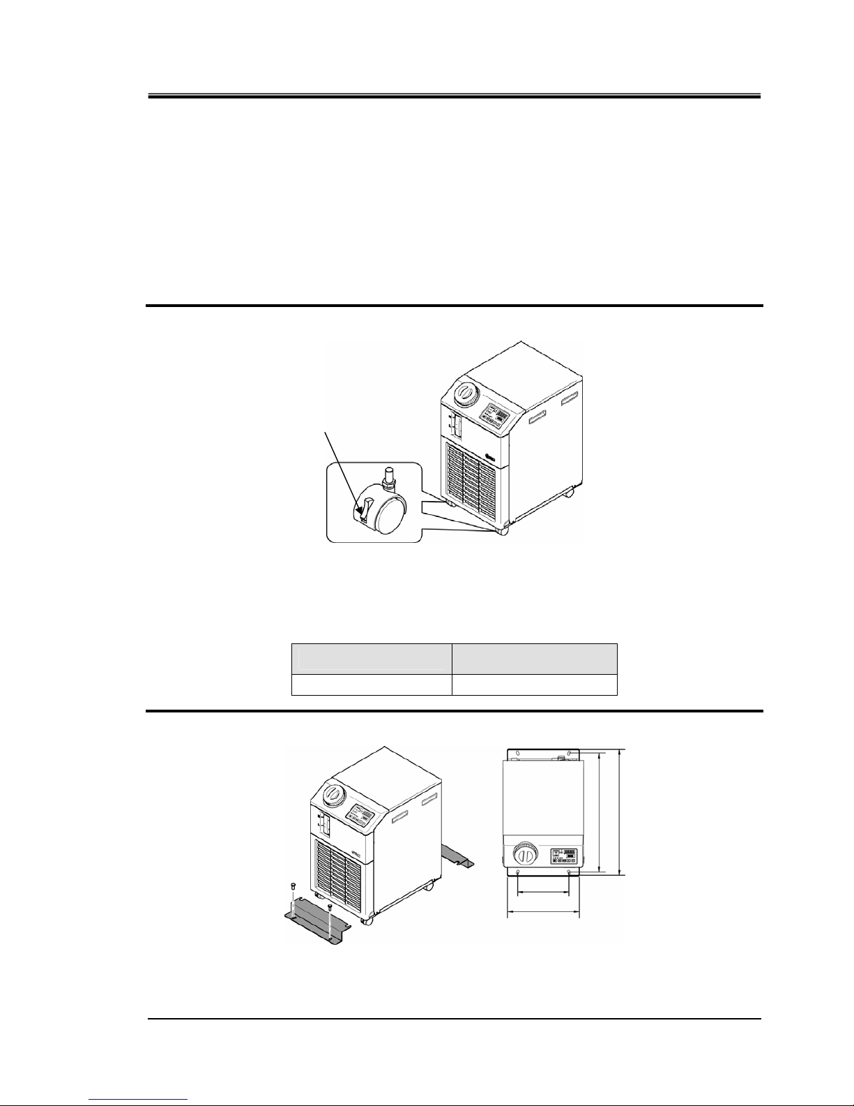
3.3.1 Mounting
z
Mount the product on a flat and stable floor with no vibrations.
z
Refer to’’8.2 Outline dimensions’’ for dimensional information of the
product.
How to mount the product
1. Move the product to the installation area.
2. After moving, lock the front casters again.
Fig. 3-3 Installation procedures
〈Fixture〉
Follow the procedure below when fixing the thermo-chiller to the floor or the mounting frame.
1. Prepare the fixing bracket shown below (Not included in the package).
Item
Part number
Anti-seismic brackets HRS-TK001
2. Use M8 foundation bolts to fix the product within the dimensions below.
Fig. 3-4 Anti-seismic brackets installing
∗4 (four) M8 foundation bolts should be prepared by the customer.
Lock
240
335
555
590
HRX-OM-M090
Chapter 3 Transport and Setting Up
3.3 Installation HRS Series
3-8
3.3.2 Electrical wiring
Power supply cable and Earth Leakage Breaker
Prepare the power supply shown in the following table. For the connection
between the product and power supply, use the power supply cable and
earth leakage breaker shown below.
If communication with the user’s machine is necessary, use the following
signal cable.
Table 3-3 Power supply cable and Earth Leakage Breaker(Recommended)
Recommended earth
leakage breaker
Model
Power supply
voltage
Cable
qty.
x size
Rated
voltage
[V]
Rated
current
[A]
Sensitivity
of leak
current [mA]
HRS012-∗∗-10
HRS018-∗∗-10
1-phase
100V AC(50Hz)
1-phase
100V to 115V
AC(60Hz)
100
200
Sharing
15 15 or 30
HRS012-∗∗-20
HRS018-∗∗-20
HRS024-∗∗-20
10 30
HRS0∗∗-∗∗-20-∗∗T
(High pump head
[Optional])
1-phase
200-230V AC
(50/60Hz)
3 cores x
14AWG
(3 cores x
2.0mm
2
)
(including
ground)
200,
230
15 30
Only qualified persons are allowed to wire the product.
Be sure to shut off the user’s power supply. Wiring with the product
energized is strictly prohibitted.
The wiring must be conducted using cables complying with “Table
3-3” firmly and secured to the product to prevent the external force
of cables being applied to the terminals. Incomplete wiring or
improper securing of wiring may cause electrical shock, excessive
heat and fire.
Ensure a stable power supply with no voltage surges.
Ensure that an Earth Leakage Breaker is used in the power supply of
the product. See “Table 3-3”.
Use a power supply suitable for the specifications of the product.
Be sure to connect the ground connection.
Ensure that a lock out facility is availble on the power supply.
Each product must have its own separate Earth Leakage Breaker.
Otherwise there can be a risk of electric shock or fire.
Do not modify the intenal electrical wiring of the product. Incorrect
wiring may cause electrical shock or fire. Also, modifing the
internal wiring will void the product’s warranty.
Do not connect the ground to water line, gas pipe or lightening
HRX-OM-M090
Chapter 3 Transport and Setting Up
HRS Series 3.3 Installation
3-9
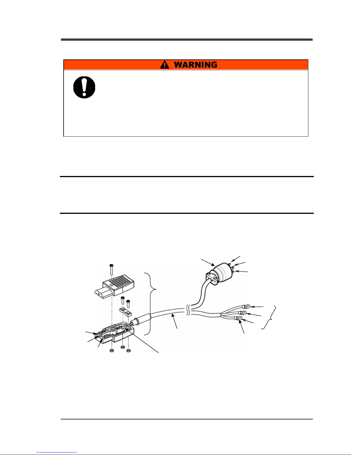
3.3.3 Preparation and wiring of power supply cable
Preparation
1. Strip the sheath from both ends of the cable.
2. Disassemble the power supply connector. Attach crimp terminals (mounting screw dia.:
M3.5) to one end of the cable to crimp them to L, N, E inside of the connector, then
reassemble the power supply connector.
3. Connect the other end of the cable to a terminal (e.g. crimped terminal) that is
compatible to the secondary side of the earth leakage breaker.
Fig. 3-5 Power supply cable
Cable
Crimped terminal
(Prepared by customer)
[Accessory]
Power supply
connector
N
E (Earth)
L
L
E
N
Earth leakage
breaker
(Secondary side)
Crimp terminal 3pcs. Terminal screw is M3.5.
Prepare the crimp terminal which is suitable for the cable
diameter.
The electrical facilities should be installed and wired in accordance
with local laws and regulations of each country and by a person
who has knowledge and experience.
Check the power supply. Operation with voltages, capacities and
frequencies other than the specified values can cause fire and
electrical shock.
Wire with an applicable cable size and terminal. Forcibly mounting
with an unsuitable size cable may result in heat generation or fire
Plug
(Prepared by customer)
L
E
N
HRX-OM-M090
Chapter 3 Transport and Setting Up
3.3 Installation HRS Series
3-10
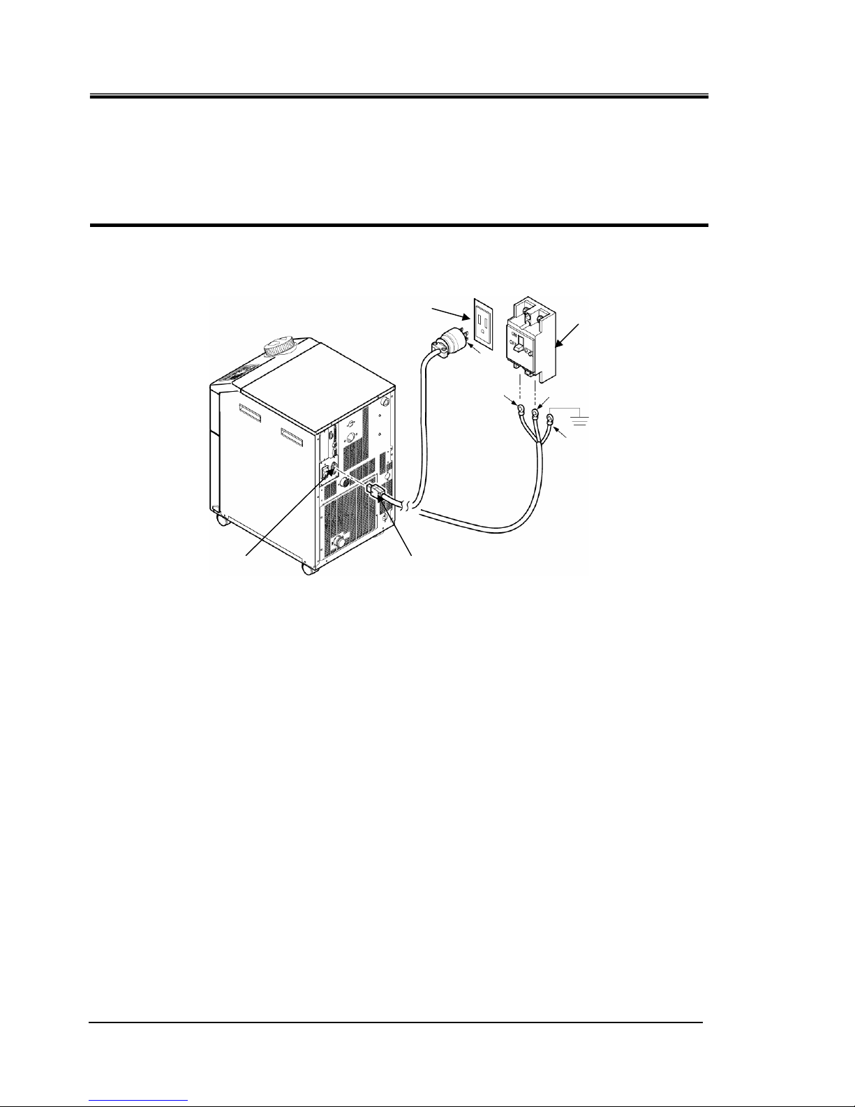
Wiring
1. Connect the power supply cable to the secondary side of the earth leakage breaker and
grounding.
2. Plug the power supply cable in to the power cable connector on the product.
Fig. 3-6 Wiring of power supply
L
N
E
Earth
Power cable hole
Earth leakage
breaker
E
Grounded socket
Power supply connector
 Loading...