

SMC Networks HRR012-W*-20, HRR018-A*-20, HRR018-W*-20, HRR024-W*-20, HRR030-W*-20 Operation Manual
...Page 1

HRX-OM-W004-A
Operation Manual
Communication function
Thermo-chiller
Air-Cooled
refrigerated type
HRR012-A
∗
-20-∗
HRR018-A
∗
-20-∗
HRR024-A
∗
-20-∗
HRR030-A
∗
-20-∗
Water-Cooled
refrigerated type
HRR012-W
∗
-20-∗
HRR018-W
∗
-20-∗
HRR024-W
∗
-20-∗
HRR030-W
∗
-20-∗
Keep this manual available whenever necessary
© 2018 SMC CORPORATION All Rights Reserved
Page 2

To Users,
Thank you for purchasing SMC’s Thermo chiller (hereinafter referred to as the “product”).
For safety and long life of the product, be sure to read this operation manual (hereinafter referred
to as the “manual”) and clearly understand the contents.
● Be sure to read and follow all instructions noted with “Warning” or “Caution” in this manual.
● This manual is intended to explain the installation and operation of the product. Only people
who understand the basic operation of the product through this manual or who performs
installation and operation of or have basic knowledge about industrial machines are allowed to
work on the product.
● This manual and other documents attached to the product do not constitute a contract, and will
not affect any existing agreements or commitments.
● It is strictly prohibited to copy this manual entirely or partially for the use by the third party
without prior permission from SMC.
Note: This manual is subject to possible change without prior notice.
Page 3

HRX-OM-W004
Contents
HRR Series
Contents
Chapter 1 Read before using ............................................................. 1-1
1.1 Communication mode and operation method ........................................................ 1-1
1.2 Communication port .................................................................................................. 1-3
1.3 Key operations ........................................................................................................... 1-4
1.4 Parameters ................................................................................................................. 1-8
Chapter 2 Contact input/output communication ............................. 2-1
2.1 Precautions for communication ............................................................................... 2-1
2.1.1 Precautions wiring communication ...................................................................................... 2-1
2.1.2 Precautions after wiring and before communication ............................................................ 2-1
2.2 Communication specification ................................................................................... 2-2
2.3 Connection explanation ............................................................................................ 2-2
2.4 Setting and checking ................................................................................................. 2-3
2.4.1 Setting and checking ............................................................................................................ 2-3
2.4.2 Setting and checking ............................................................................................................ 2-4
2.5 Contact input signal ................................................................................................ 2-12
2.5.1 Run/stop・Run・Stop・External switch signal ....................................................................... 2-13
2.5.2 Signal of the external switch .............................................................................................. 2-14
2.6 Contact output signal .............................................................................................. 2-16
Chapter 3 Serial communication ....................................................... 3-1
3.1 Precautions wiring communication ......................................................................... 3-1
3.2 Connected explanation ............................................................................................. 3-1
3.3 Communication specification ................................................................................... 3-2
3.4 MODBUS communication function .......................................................................... 3-3
3.5 Precautions for communication ............................................................................... 3-3
3.5.1 Precautions after wiring and before communication ............................................................ 3-3
3.5.2 Precautions for communicating ............................................................................................ 3-3
3.6 Setting and checking ................................................................................................. 3-4
3.6.1 Setting and checking items .................................................................................................. 3-4
3.6.2 Setting and checking ............................................................................................................ 3-5
3.7 Communication sequence ........................................................................................ 3-7
3.8 Message configuration .............................................................................................. 3-8
3.8.1 Message frame .................................................................................................................... 3-8
3.9 Function codes .......................................................................................................... 3-9
3.10 Checksum calculation method ............................................................................... 3-10
3.10.1 LRC(ASCII) ........................................................................................................................ 3-10
3.10.2 CRC(RTU) .......................................................................................................................... 3-10
3.11 Explanation of function codes ................................................................................ 3-12
3.11.1 Function code:04 Reading multiple registers .................................................................... 3-12
3.11.2 Function code:06 Writing registers .................................................................................... 3-13
3.11.3 Function code:16 Writing multiple registers ...................................................................... 3-14
Page 4

HRX-OM-W004
Contents
HRR Series
3.11.4 Function code:23 Reading/writing multiple registers ........................................................ 3-15
3.12 Negative response ................................................................................................... 3-16
3.13 Register Map ............................................................................................................ 3-18
3.13.1 Circulating fluid discharge temperature ............................................................................. 3-19
3.13.2 Circulating fluid flow rate ................................................................................................... 3-19
3.13.3 Circulating fluid discharge pressur .................................................................................... 3-19
3.13.4 Electric conductivity of the circulating fluid ........................................................................ 3-19
3.13.5 Status flag .......................................................................................................................... 3-19
3.13.6 Alarm flag........................................................................................................................... 3-20
3.13.7 Data instruction information ............................................................................................... 3-21
3.13.8 Data display ....................................................................................................................... 3-21
3.13.9 Circulating fluid set temperature ........................................................................................ 3-21
3.13.10 Operation Start Command................................................................................................. 3-21
3.13.11 Serial remote instruction .................................................................................................... 3-21
3.13.12 Data instruction .................................................................................................................. 3-22
Chapter 4 Communication alarm function ....................................... 4-1
4.1 Communication alarm occurs .................................................................................. 4-1
4.2 Communication alarm reset ...................................................................................... 4-2
4.3 Setting and checking ................................................................................................. 4-2
4.3.1 Setting and checking items.................................................................................................. 4-2
4.3.2 Setting and checking ........................................................................................................... 4-3
Page 5

HRX-OM-W004
Chapter 1 Read before using
HRR Series 1.1 Communication mode and operation method
1-1
Chapter 1 Read before using
The communication of this device consists of contact input/output
communication and serial communication.
The serial communication protocol is a MODBUS communication.
Depending on the customer’s specification, communication can be
changed to contact input/output communication or serial
communication.
Table 1-1 Communication method
Contact input/output communication.
This product is equipped with a terminal which
runs/stops the product by remote control and a terminal which
can pick up alarm signals. The terminals can be changed
depending on the customer’s application.
Serial
communication
MODBUS standard
protocol
Serial communication (RS-485/RS232C) enables remote
control of run/start of the product, temperature setting, and
details of product condition and alarm condition can be obtained.
●If using contact input/output communication, refer to
chapter 2.
●If using serial communication MODBUS, refer to chapter
3.
1.1 Communication mode and operation method
LOCAL, DIO and SERIAL are available as the communication modes.
Table
1.1-1 explains the communication modes. The default setting is
LOCAL.
The operation method depends on the communication mode. Table
1.1-2 shows how the communication mode and method of operation
are related.
Page 6
HRX-OM-W004
Chapter 1 Read before using
1.1 Communication mode and operation method
HRR Series
1-2
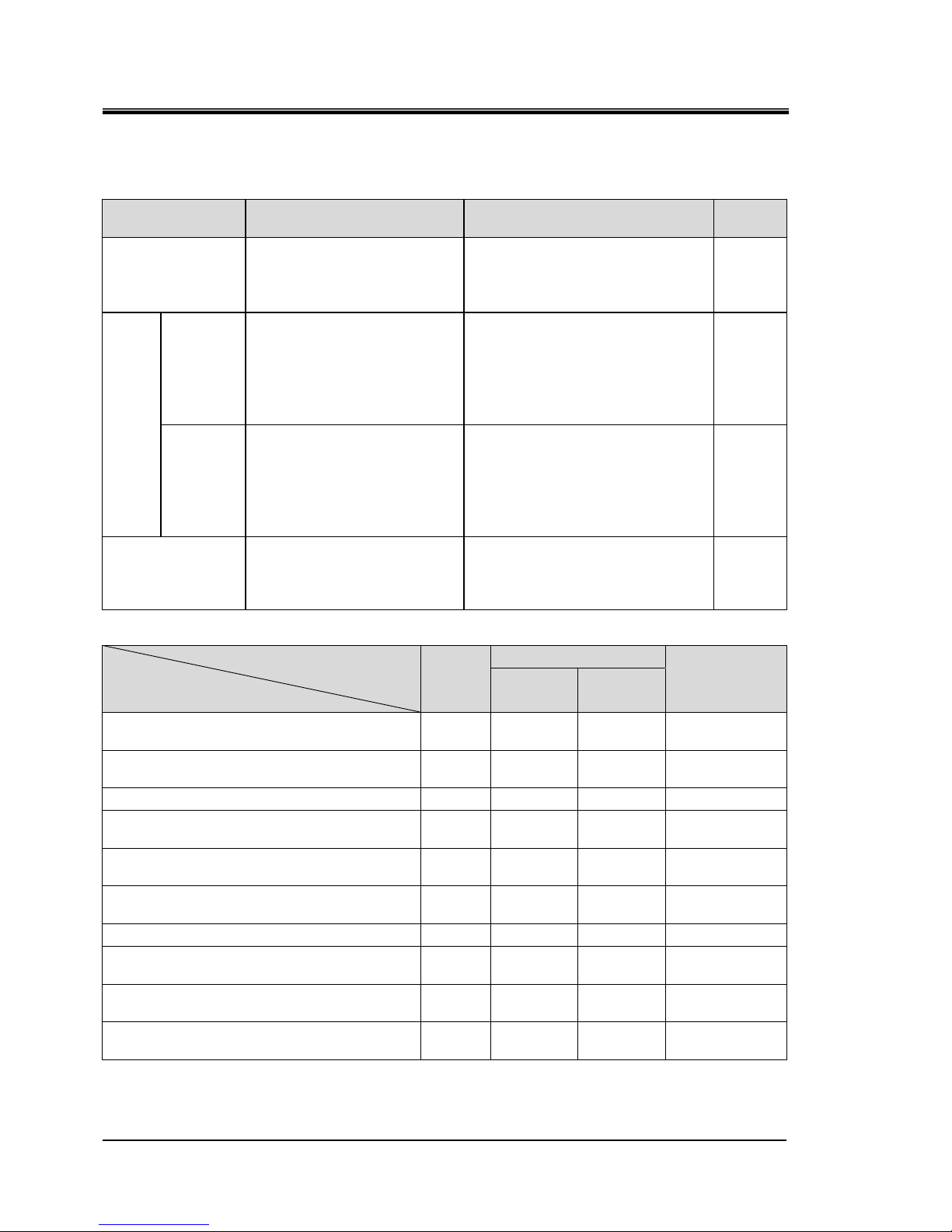
Table 1.1-1 Communication modes.
Communication
mode
Explanation Setting Display
LOCAL
Run / stop and circulating
fluid temperature setting are
possible with the operation
panel.
Select contact input signal
function 1 selection to "OFF"
(initial setting) / "SW".
None
DIO
REMOTE
Run / stop with contact
input,
and set circulating fluid
temperature on the
operation
panel.
Select contact input signal
function 1 selection as
"RN.ST" / "RUN".
RMT
Lamp
Lighting
up
LOCAL
Run / stop with the operation
panel or contact input.
Set the circulating fluid
temperature on the
operation
panel.
When the operation of the
contact input signal function 1
is selected as "MT" in the state
of DIO REMOTE, it becomes
"DIO LOCAL"
RMT
Lamp
Lighting
up
SERIAL
Run / stop and circulating
fluid temperature setting are
possible with the serial
communication
When serial remote instruction is
valid, this mode is switched.
RMT
Lamp
Lighting
up
Table 1.1-2 Communication mode and operation
LOCAL
DIO
SERIAL
DIO
LOCAL
DIO
REMOTE
Run/Stop control with operation
display panel
○ ○ × ○
Circulating fluid discharge temperature
setting control with operation display panel
○ ○ ○ ×
Except above with operation display panel
○ ○ ○ ○
Condition reading with operation
display panel
○ ○ ○ ○
Run/Stop operation by contact input/output
communication
× ○ ○ ×
Condition reading by contact input/output
communication
○ ○ ○ ○
Reading of the external switch
○ ○∗1 ○∗1 ○
Run/Stop operation by serial
communication.
× × × ○
Circulating fluid discharge temperature
setting control by serial communication.
× × × ○
Condition reading by serial
communication.
○ ○ ○ ○
∗1 Only one external switch can be installed.
Page 7
HRX-OM-W004
Chapter 1 Read before using
HRR Series 1.2 Communication port
1-3
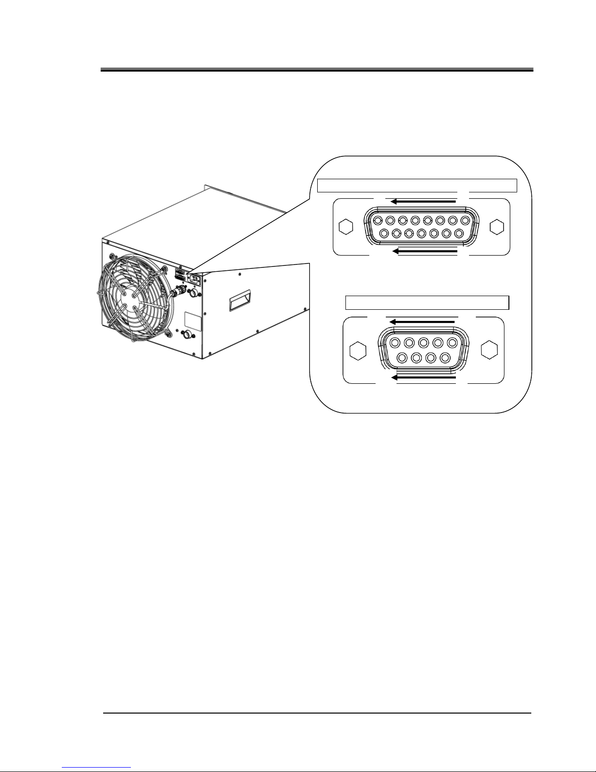
1.2 Communication port
The communication port at the back of the product is used for communication.
Fig 1.2-1 shows the location of the communication port.
Fig 1.2-1 Communication port
Dsub 15 pin female (socket) type
Dsub 9 pin female (socket) type
Connector for contact input / output signal
Serial communication connector
8
1
15
9
5
1
9
6
Page 8
HRX-OM-W004
Chapter 1 Read before using
1.3 Key operations
HRR Series
1-4
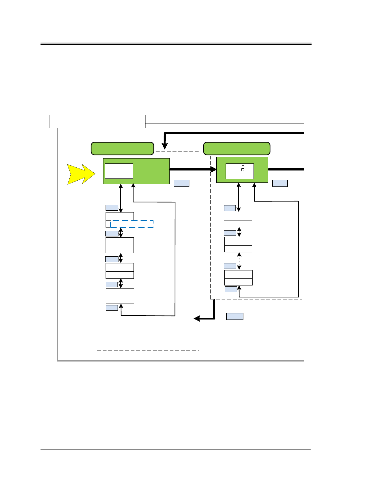
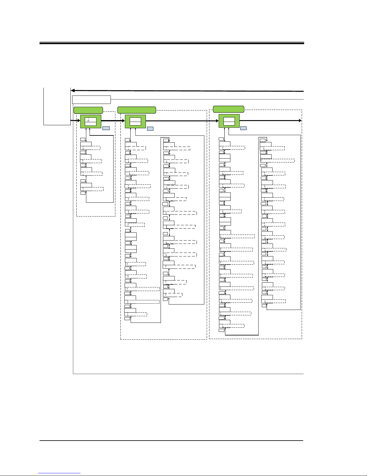
1.3 Key operations
Fig 1.3-1‘’Key operation(1/4)’’ and
Fig1.3-4 ‘’Key operation(4/4)’’ show the operation of keys of the
thermo-chiller. This manual explains the “Communication setting menu”.
Fig 1.3-1 Key operation (1/4)
MENU
Main menu
Power supply ON
Allarm number
(Allarm number
maximum)
Alarm display menu
Allarm number
AL01
Allarm number
(Alarm number minimum)
AL02
ALXX
MENU
AL
XXALM
Basic setting mode
00
circulating fluid return
temp
014
Circulating fluid
outlet pressure
123
DIPV
Electric
conductivity∗
(μS/cm)
PRESS
79
Circulating fluid
flow rate
FLOW
RET ⇔ TEMP
▲/▼
▲/▼
▲/▼
▲/▼
▲/▼
▲/▼
▲/▼
▲/▼
▲/▼
200
200
Circulating fluid
outlet temperature
Circulating fluid set
temperature
∗ Option D【Electric conductivity control function】 only
RESET
Displays only when the alam is generated.
Page 9
HRX-OM-W004
Chapter 1 Read before using
HRR Series 1.3 Key operations
1-5
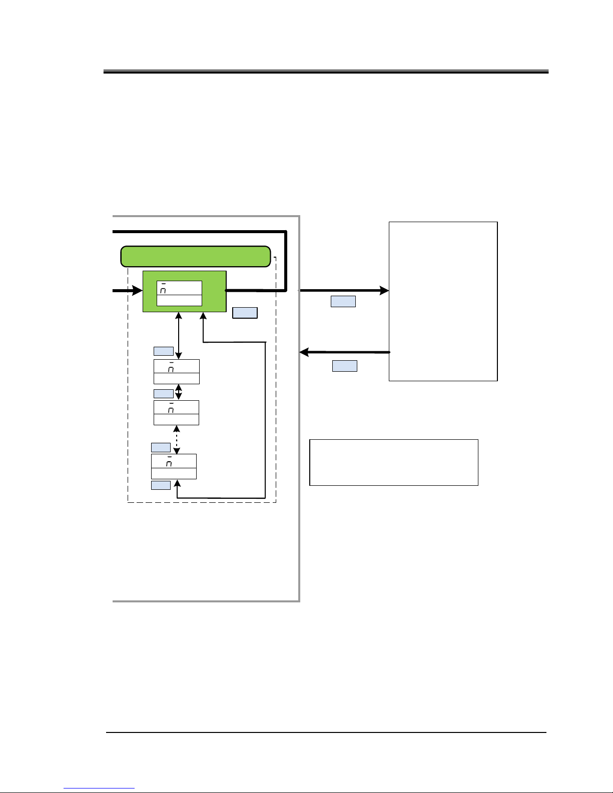
Fig 1.3-2 Key operation (2/4)
MENU
Maintenance
notification number
(Maintenance number
maximum)
Maintenance notification menu
Maintenance
notification
number
T01
Maintenance
notification number
(Notification number
Minimum)
TNN
▲/▼
▲/▼
▲/▼
▲/▼
ANT
MENU
T02
Advanced
setting
mode
To switch to 「Advanced setting
mode」 press and hold 「MENU」
key for 5 seconds
MENU
MENU
Press and hold
for approximately
5 second.
Displays only when the maintenance notice is generated.
Page 10
HRX-OM-W004
Chapter 1 Read before using
1.3 Key operations
HRR Series
1-6
Fig 1.3-3 Key operation (3/4)
EASY mode
resetKey cl ick sound
Electric conductivity
set valve hysteresis*1
Unuse
d
ON
ON
WAKE
250
DISP
50
DIHYS
OFF
EXTMD
PUMPF
00
▲/▼
▲/▼
▲/▼
▲/▼
▲/▼
Key-lock
OFF
▲/▼
Circulating fluid temp time
outside monitoring range
5
WRM
▲/▼
SET
MENU
MENU
KEY ⇒ LOCK
EASY ⇒ MODE
KEY ⇒ CLICK
Offset mode
OFF
▲/▼
OFSET ⇒ MODE
00
▲/▼
OFSET ⇒ TEMP
▲/▼
EXT ⇔ OFSET
TEMP ⇒ OUT ⇒ OVER
DI filter maintenance
time*1
Dustproof filter
maintenance time
*Air-coold type only
5000
FILTT
5000
FUNUP
▲/▼
▲/▼
▲/▼
DI ⇔ TIME
050
5
WRN
HIPRS
HIPRS
HITEM
40
LOFL
5
LOTEM
450
DIHI
ON
ON
OFF
400
Detection time of circulating
fluid discharg e pressure
rise alarm
Changing of the flow
rate decrease alarm
Setting of low flow
rate alarm
Detection time of low
flow rate alarm
Setting of electric
conductivity increase
alarm*1
Switching circulating fluid
temperature drop alarm
Switching circulating fluid
temperature drop alarm
Unused
Unused
Setting of circulating fluid
discharge pressure
rise alarm
▲/▼
▲/▼
▲/▼
▲/▼
▲/▼
▲/▼
▲/▼
▲/▼
▲/▼
▲/▼
FLT
Changing of circulating fluid
discharge pressure
rise alarm
▲/▼
ALST
MENU
▲/▼
MENU
HIPRS ⇒ ALARM
TEMP ⇒ OUTHI ⇒ OUTP
TEMP ⇒ OUTLO ⇒OUTP
AMB ⇒ TEMP ⇒ ALARM
AMB ⇒ HITEMP
Alarm setting menu
FLTR ⇔ TIME
Lower limit of circulati ng
fluid temperature
monitoring function
Circulating fluid temp
monitoring start time
PUMPP
600
WRM
50
▲/▼
▲/▼
TEMP ⇒ OUT ⇒ TYPE
TEMP ⇒ OUT ⇒ START
HIPRS ⇒ TIME
LOFL ⇒ ALARM
LOFL ⇒ TIME
OFF
Switching circulating fluid
temperature range rising
alarm
▲/▼
TEMP ⇒ OUTLO ⇒ ALARM
Alarm buzzer sound
ON
ALARM ⇒ BUZZ
▲/▼
Unused
Pressure of lower
pressure refrigerant
circuit
Pressure of higher
pressu reref rigerant
circuit
000
000
▲/▼
▲/▼
ON
MENU
MENU
REF ⇔ PRSHI
REF ⇔ PRSLO
212
▲/▼
REF ⇔ TEMP
Ambient temperature
*Air-cooled type only
212
AMB ⇔ TEMP
▲/▼
▲/▼
Advance setting mode
0
0
WRN
Contact input signal 2
Delay timer
Contact input signal 2
OFF Detection timer
▲/▼
▲/▼
▲/▼
INP2 ⇒ DELAY
INP2 ⇒ OVER
COMM ⇒ ALARM
Changing of
communication error
monitoring alaarm
OFF
▲/▼
MANT ⇒ ALARM
Changing of
maintenance alarm
Monitor menu
Standard setting menu
Offset temperature
Electric conductivit y set
valve* 1
PUMPF
350
▲/▼
Unuse
d
FLT
Changing of contact
input signal 2 detection
alarm
INP2 ⇒ ALARM
▲/▼
Switching circulating fluid
temperature range rising
alarm
OFF
PUMPF
▲/▼
TEMP ⇒ OUTHI ⇒ ALARM
0
0
INP2
INP2
Contact input signal
1Delay timer of reading
Contact input signal 1
OFF Detection timer
▲/▼
▲/▼
INP1 ⇒ DELAY
FLT
Changing of contact
input signal 1 signal
detection
INP1 ⇒ ALARM
▲/▼
EXT ⇔ CTRL
EXT ⇒ HITMP ⇒ LIMIT
Upper limit of circul ating
fluid temperature
monitoring function
400
▲/▼
TEMP ⇒ OUT ⇒ HITMP
Unused
10
WAKE
Unuse
d
100
▲/▼
EXT ⇒ LOTMP ⇒ LIMIT
EXT ⇔ TIME
▲/▼
Temperature of the
compressor inlet
Basic
setting
mode
10
READY ⇒ HBEND
TEMP READYband
width Upper Limit
▲/▼
-10
▲/▼
READY ⇒ LBRND
TEMP READY Band
width Lower Limit
180
▲/▼
READY ⇒ TIME
TTEMP READY
stabilization time
600
▲/▼
READY ⇒ START
TTEMP READY alarm
monitoring start time
5
▲/▼
TEMP ⇒ OVER
TTEMP READY
Time when it goes away
▲/▼
▲/▼
TEMP READY alarm
OFF
PUMPF
TEMP ⇒ READY ⇒ ALARM
TEMP READY alarm output
added
ON
PUMPF
TEMP ⇒ READY ⇒ OUTP
▲/▼
100
Unused
▲/▼
AMB ⇒ LOTEMP
ARN
Switch leakage alarm
WATER ⇒ LEAK ⇒ ALARM
▲/▼
▲/▼
INP1 ⇒ OVER
30
▲/▼
COMM ⇒ TIME
The monitoring time of
communication error
0
PUMP ⇒ TIME
Time when only pump
rus when alarm is generated
▲/▼
400
PUMP ⇒ TEMP
Temp when only pump
rus when alarm is generated
▲/▼
CTRL
dDI
▲/▼
Electric conductivity
control methhod* 1
DI ⇒ CTRL
Circulating fluid temperature
range increases, the monitoring
method of lowering alarm
RNST
WRM
TEMP ⇒ OUT ⇒ ALARM
▲/▼
Page 11
HRX-OM-W004
Chapter 1 Read before using
HRR Series 1.3 Key operations
1-7
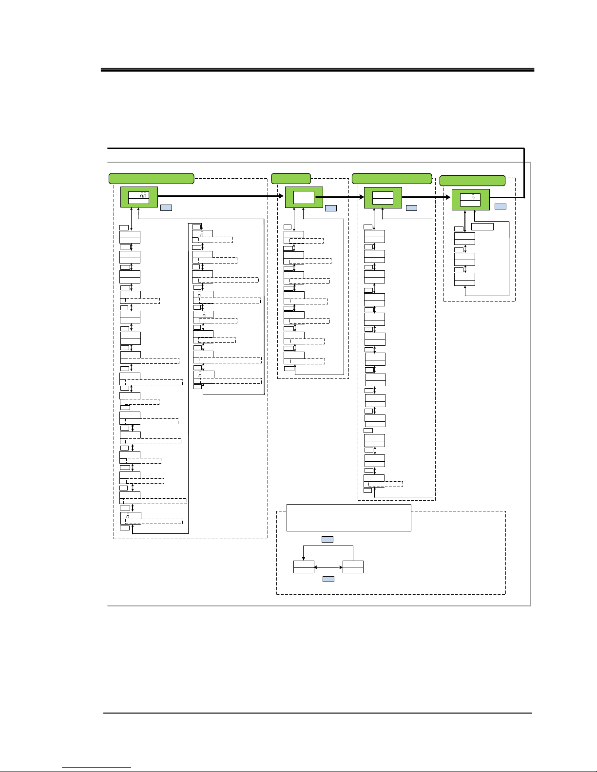
Fig 1.3-4 Key operation (4/4)
ASC
485
OFF
PROT
TYPE
TERM
1
192
SPEED
T01
DIN1
ALT
INP1
Serialprotocol
Communication
specifications
Slave address
Communication speed
RS-485terminal
Digital input signal 1
Selective Maintenance
▲/▼
▲/▼
▲/▼
▲/▼
▲/▼
▲/▼
▲/▼
▲/▼
MENU
OFF
INP2
ALT
INP2
A
INP2
A
OUT1
Digital input
signal 2
operation
Digital output signal 1
operation
Digital input signal 2
function selection
Digital input signal 2 type
▲/▼
▲/▼
▲/▼
▲/▼
A
INP1
Contact inputsignal 1
operation
▲/▼
DIN2 ⇔ SEL
DOUT1 ⇒ TYPE
SLV ⇔ ADDR
NO
MODE
Setting date reset
RST
MENU
MENU
ALL ⇔ RESET
Communication setting menu Reset menu
R T
OUT2
OUT2
AL01
OUT2
AL
OUT3
B
OUT3
AL01
OUT3
Digital output 2
selected alarm
Digital output signal 3
selected alarm
Digital output signal 2
function selection
Digital output signal 2
operation
Digital output signal 3
function selection
Digital output signal 3
operation
▲/▼
▲/▼
▲/▼
▲/▼
▲/▼
▲/▼
DOUT2 ⇔ SEL
DOUT2 ⇔ TYPE
DOUT3 ⇔ SEL
DOUT3 ⇔ TYPE
▲/▼
0
Operation time
Pump operation time
Accumulated operation time
of the dust-proof filter
Accumulated operation
time of the DI filter ∗1
DIT
0
RUNT
0
PUMPT
0
COMPT
0
FLTRT
▲/▼
▲/▼
▲/▼
▲/▼
▲/▼
Compressor
operation time
0
FANT
▲/▼
Fan operation time
*Air-cooled type only
INFO
MENU
Information moniter menu
00
PGVER
Program version
▲/▼
0000
PGNO
Program number
▲/▼
▲/▼
MENU
Digital input
signal 1 type
OUT1
RUN
Digital output signal 1
function selection
▲/▼
DOUT1 ⇒ SEL
OUT1
AL01
Digital output signal 1
selected alarm
DIN1 ⇒ SW ⇒ TYPE
DIN1 ⇒ CON ⇒ TYPE
DIN2 ⇒ SW ⇒ TYPE
DIN2 ⇒ CON ⇒ TYPE
DOUT1 ⇒ ALARM ⇒ CODE
A
▲/▼
DOUT2 ⇒ ALARM ⇒ CODE
OUT1
T01
Digital output 2
selected maintenance
DOUT2 ⇒ MANT ⇒ CODE
OUT1
T01
Digital output 3
selected maintenan ce
DOUT3 ⇒ MANT ⇒ CODE
DOUT3 ⇒ ALARM ⇒ CODE
▲/▼
▲/▼
DOUTI⇒ MANT ⇒ CODE
aAL h
nnn
Alarm history menu
MENU
AL17
Alarm
(The latest)
▲/▼
OFF
DINI
▲/▼
Digital input signal 1
function selection
hRR
018-R
Model
▲/▼
20-
DMTU
Power Options
▲/▼
Example
AL10
Alarm
▲/▼
ALNN
Alarm
(The oldest)
▲/▼
*1:With electric conductivity
control function only
0
Number of times of
momentary power failure
POWF
▲/▼
NO
NO
PROT
Reset of dust-proof
filter operation time
DI filter
Reset usage time
▲/▼
▲/▼
FLTRT ⇒ RESET
DIT ⇒ RESET
▲/▼
NO
PROT
Reset of pump
operation time
▲/▼
PUMPT ⇒ RESET
NO
PROT
Reset of compressor
operation time
▲/▼
COMPT ⇒ RESET
NO
PROT
Reset of fan
operation time
▲/▼
FANT ⇒ RESET
OFF
Forced DI solenoid
valve
open
DI ⇒ VALVE
0000
instantaneous power failure
occurrence count
DIT
▲/▼
▲/▼
▲/▼
CO
MENU
STD
WS001
standard product/
special numbers
▲/▼
SELIAL.NO
*2
By pressing the ENT key on each alarm history screen,
accumulated operating time and the number of
historcases at the time of occurrence are displayed.
AL10
123
NO2
MENU
ENT
Accumulated operating time at alarm accurrence is displayed
Alarm log number
COMM ⇒ STUS
Page 12

HRX-OM-W004
Chapter 1 Read before using
1.4 Parameters
HRR Series
1-8
1.4 Parameters
Table 1.4-1 ‘’Communication setting menu Parameters’’ explains the
parameters of the 「communication setting menu」.
Table 1.4-1 Communication setting menu Parameters
∗1 Selectable from OFF/RUN/RMT/EXT.C/RDY/T.OUT/FLT/WRN/MENT/ALM/SW1/SW2/A.SEL/M.SEL
Initial value Select/setting range
TOP
screen
-
COMM
-
MEN U -
No.1
screen
Serial protocol
ASC AS C/ RTU PR OT
No.2
screen
Communic ation specification
485 485/232C TYPE
No.3
screen
RS-485 terminal unit
OFF OFF/ON TERM
No.4
screen
Slave address
11
~
32 SLV ⇒ ADDR
No.5
screen
Communic ation speed
(
bps
)
19.2 9.6/19.2 SPEED
No.6
screen
Contact input signal 1 function OFF OFF/RN.ST/RUN/SW D.IN1 ⇒ SEL
No.7
screen
Contact input signal 1 type ALT ALT/MT D.IN 1 ⇒ SW ⇒ TYPE
No.8
screen
Contact input signal 1 operation A A/B D.IN1 ⇒ CON ⇒ TYPE
No.9
screen
Contact input signal 2 function OFF OFF/STOP/SW D.IN2 ⇒ SEL
No.10
screen
Contact input signal 2 type ALT ALT/MT D.IN 2 ⇒ SW ⇒ TYPE
No.11
screen
Contact input signal 2 operation A A/B D.IN2 ⇒ CON ⇒ TYPE
No.12
screen
Contact output signal 1 function RUN
∗
1D.OUT1
⇒
SEL
No.13
screen
Contact output signal 1 operation A A/B D.OUT1 ⇒ TYPE
No.14
screen
Contact output signal 1
alarm
AL.01 AL.01~AL .32 D .OU T1 ⇒ ALARM ⇒ CODE
No.15
screen
Contact output signal 1 maintenance MT.01 MT.01~MT. 05 D.O UT1⇒ MANT ⇒ CODE
No.16
screen
Contact output signal 2 function RMT
∗
1D.OUT2
⇒
SEL
No.17
screen
Contact output signal 2 operation A A/B D.OUT2 ⇒ TYPE
No.18
scree
Contact output signal 2
alarm
AL.01 AL.01~AL .32 D .OU T2 ⇒ ALARM ⇒ CODE
No.19
screen
Contact output signal 2 maintenance MT.01 MT.01~MT.05 D.OUT2 ⇒ MANT ⇒ CODE
No.20
screen
Contact output signal 3 function ALM
∗
1D.OUT3
⇒
SEL
No.21
screen
Contact output signal 3 operation B A/B D.OUT3 ⇒ TYPE
No.22
screen
Contact output signal 3
alarm
AL.01 AL.01~AL .32 D .OU T3 ⇒ ALARM ⇒ CODE
No.23
screen
Contact output signal 3 maintenance MT.01 MT.01~MT.05 D.OUT3 ⇒ MANT ⇒ CODE
3.5.2
2.4.2
ScreenNo. Item
Display unit
Reference
page
Upper stage(White
)
Lower stage
(
Green
)
Page 13

HRX-OM-W004
Chapter 2 Contact input/output communication
HRR Series 2.1 Precautions for communication
2-1
Chapter 2 Contact input/output
communication
The device is equipped with a terminal which runs/stops the product. It is also
equipped with a terminal which picks up operation signals, alarm signals and
setting condition.
The device starts contact input/output communication according to the setting
of the operation display panel. Contact input/output communication can be
customized by changing the settings. Table 2-1 ‘’Customizable content’’
shows the contents which can be changed by the operation display panel.
Table 2-1 Customizable content
Signal Can be changed
Contact input signal (2pcs.) Signal configuration (Alternate/Momentary)
Contact output signal (3pcs.) Type of signal, signal operation (N.O type / N.C type)
2.1 Precautions for communication
2.1.1 Precautions wiring communication
○Communication wiring
A communication cable that connects the product and customer system is not
included with the product. Please prepare a cable, referring to 2.3
“Connection explanation“. In order to avoid malfunction, do not connect to
any place other than those shown in 2.3 “Connection explanation“.
○Power supply
To use the power of the product, the total load current must be 500mA or
less.
2.1.2 Precautions after wiring and before communication
○Check or set the communication mode by the operation display panel.
・Communication mode shall be DIO.
Other modes can perform reading, but only DIO mode can perform writing.
Page 14
HRX-OM-W004
Chapter 2 Contact input/output communication
2.2 Communication specification HRR Series
2-2
2.2 Communication specification
Table 2.2-1 DIO Communication specification
Item Specification
Connector type(for this product) Dsub 15P type female connector
Contact input
signal
Insulation system
Photo coupler
Rated input voltage
DC24V
Used input voltage
DC 21.6 to 26.4V
Rated input current
5mA TYP
Input signal
4.7kΩ
Contact output
signal
Rated load voltage
AC48V or less/DC30V or less
Maximum load current
AC/DC 500mA (Resistance load)
Minimum load current DC5V 10mA
DC24V output voltage
DC24V±10% 500mA MAX
(It can not be used for inductive load.)
2.3 Connection explanation
This part explains the port of the contact input/output communication. A
communication cable that connects the product and customer system is not
included with the product.
Table 2.3-1 Contact input/output pin number
PIN
no
Application Division Default setting
Setting
available
1 DC 24V output Output
2 DC 24V output Output
3 DC 24V output Output
4 Contact input signal 1 Input None
○
5 Common of contact output signal 1 Output
6 Common of contact output signal 2 Output
7 Common of contact output signal 3 Output
8 None -
9 24 COM output Output
10 24 COM output Output
11 Common of contact input signal Output
12 Contact input signal 2 Input None
○
13 Contact output signal 1 Output
Run status signal
(N.O. type)
○
14 Contact output signal 2 Output Remote signal (N.O. type)
○
15 Contact output signal 3 Output Alarm signal (N.C. type)
○
Page 15

HRX-OM-W004
Chapter 2 Contact input/output communication
HRR Series 2.4 Setting and checking
2-3
2.4 Setting and checking
2.4.1 Setting and checking
The table below explains the setting items of the contact input/output signal
and the initial values.
Table 2.4-1 List of set communication items
*1:Selectable from OFF/RUN/RMT/EXT.C/RDY/T.OUT/FLT/WRN/MENT/ALM/SW1/SW2/
A.SEL/M.SEL
Initial
va lu e
Select/setting range
TOP
screen
-
COMM
-
MEN U
Com m un icati on s etting m enu
TOP screen
No.6
screen
Contact input
signal 1 function
OFF OFF/RN .ST/R UN /SW
D.IN1
⇒
SEL
Setting function of contact input
signal 1.
No.7
screen
Contact input
signal 1 type
AL T AL T/MT
D.IN1
⇒
SW
⇒
TYPE
Setting input type of contact
input signal 1.
No.8
screen
Contact input
signal 1
operation
AA/B
D.IN1
⇒
CON
⇒
TYPE
Setting input operation of
contact input signal 1.
No.9
screen
Contact input
signal 2 function
OFF OFF/STOP/SW
D.IN2
⇒
SEL
Setting function of contact input
signal 2.
No.10
screen
Contact input
signal 2 type
AL T AL T/MT
D.IN2
⇒
SW
⇒
TYPE
Setting input type of contact
input signal 2.
No.11
screen
Contact input
signal 2
operation
AA/B
D.IN2
⇒
CON
⇒
TYPE
Setting input operation of
contact input signal 2.
No.12
screen
Contact output
signal 1 function
RUN
※
1
D.OUT1
⇒
SEL
Setting function of contact input
signal 1.
No.13
screen
Contact output
signal 1
operation
AA/B
D.OUT1
⇒
TYPE
Setting output operation of
contact output signal 1.
No.14
screen
Contact output
signal 1alarm
AL .0 1 AL .0 1~AL .3 2
D.OUT1
⇒
ALARM
⇒
CODE
Setting selected alarm of
contact output signal 1.
No.15
screen
Contact output
signal 1
maintenance
MT. 01 MT. 01~MT. 05
D.OUT1
⇒
MANT
⇒
CODE
Setting selected maintenance of
contact output signal 1.
No.16
screen
Contact output
signal 2 function
RMT
※
1
D.OUT2
⇒
SEL
Setting function of contact output
signal 2.
No.17
screen
Contact output
signal 2
operation
AA/B
D.OUT2
⇒
TYPE
Setting output operation of
contact output signal 2.
No.18
screen
Contact output
signal 2 alarm
AL .0 1 AL .0 1~AL .3 2
D.OUT2
⇒
ALARM
⇒
CODE
Setting selected alarm of
contact output signal 2.
No.19
screen
Contact output
signal 2
maintenance
MT. 01 MT. 01~MT. 05
D.OUT2
⇒
MANT
⇒
CODE
Setting selected maintenance of
contact output signal 2.
No.20
screen
Contact output
signal 3 function
AL M
※
1
D.OUT3
⇒
SEL
Setting function of contact output
signal 3.
No.21
screen
Contact output
signal 3
operation
BA/B
D.OUT3
⇒
TYPE
Setting output operation of
contact output signal 3.
No.22
screen
Contact output
signal 3 alarm
AL .0 1 AL .0 1~AL .3 2
D.OUT3
⇒
ALARM
⇒
CODE
Setting selected alarm of
contact output signal 3.
No.23
screen
Contact output
signal 3
maintenance
MT. 01 MT. 01~MT. 05
D.OUT3
⇒
MANT
⇒
CODE
Setting selected maintenance of
contact output signal 3.
Display
No.
Item
Display unit
Contents
Upper stage(White
)
Lower
stage
(
Green
)
Page 16
HRX-OM-W004
Chapter 2 Contact input/output communication
2.4 Setting and checking HRR Series
2-4
2.4.2 Setting and checking
Communication setting menu TOP screen
1. Displays communication setting menu.
Contact input signal 1 function
2. Press the [▼] key. Displays screen for setting the function of the Contact input signal 1
Displays the function for the Contact input signal 1.
Set value Contents
Initial value
OFF
No input signal
○
RNST
Run / stop signal is input
―
RUN
Run signal is input
―
SW
External switch signal input
―
℃
Main menu
TOP
screen
[MENU] key
Press and hold
(5 seconds)
Monitor Menu
TOP
screen
[MENU]
key
Standard setting menu
TOP
screen
[MENU]
key
Alarm setting menu
TOP
screen
Communication setting menu
TOP
screen
[MENU]
key
[MENU]
key
[MENU]
key
Contact input signal 1 function
DIN1 ⇒ SEL(Alternately displayed)
Page 17
HRX-OM-W004
Chapter 2 Contact input/output communication
HRR Series 2.4 Setting and checking
2-5
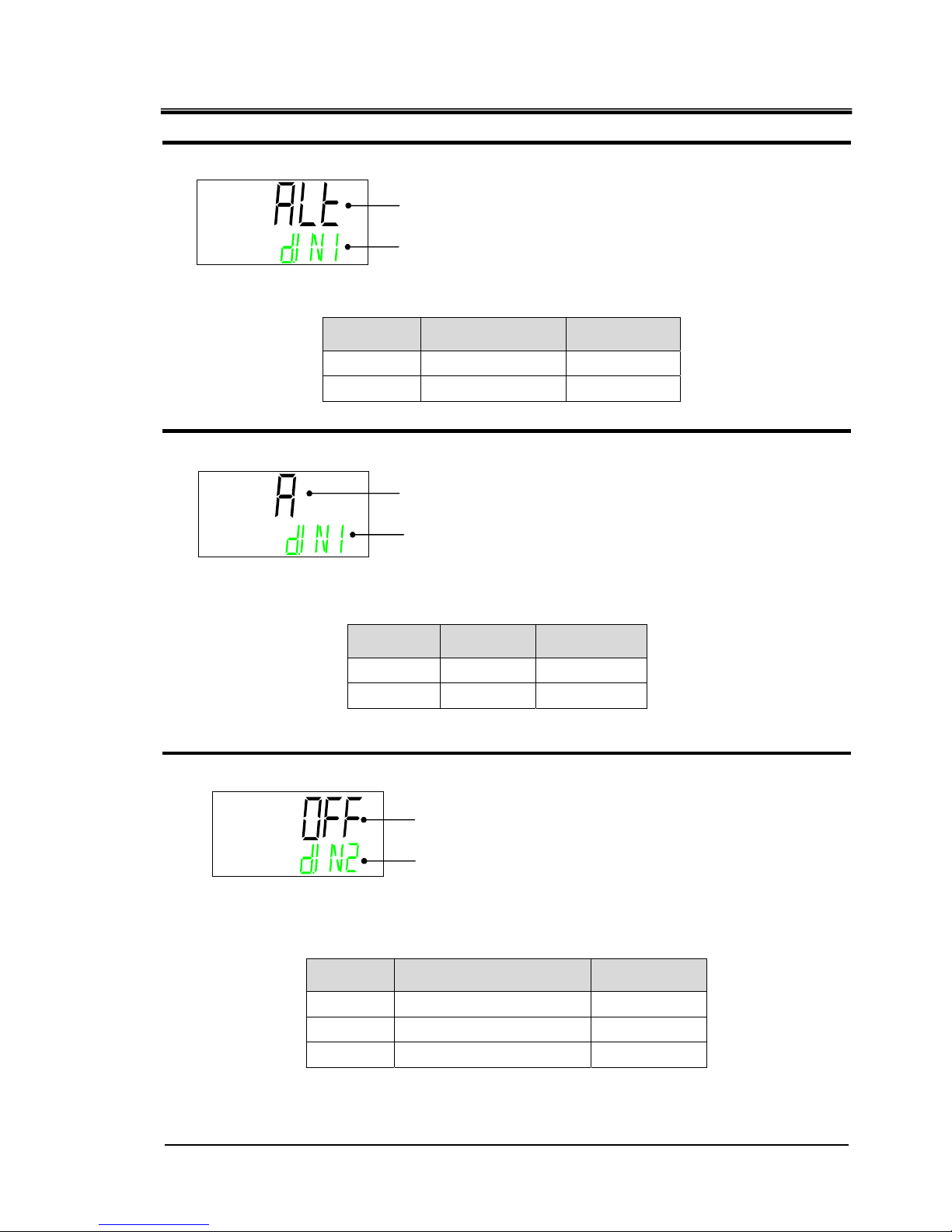
Contact input signal 1 type
3. Press the [▼] key. Displays screen for setting the type of Contact input signal 1.
Displays the type of Contact input signal 1.
Contact input signal 1
operation
4. Press the [▼] key. Displays screen for setting the operation of the Contact input signal 1.
Select the Contact input signal 1 operation.
Contact input signal 2 Select function
5. Press the [▼] key. Displays screen for setting the function of the Contact input signal 2.
Displays the function of the Contact input signal 2.
Set value Contents
Initial value
OFF
No input signal
○
STOP
Stop signal input
―
SW
External switch signal input
―
Set value Contents
Initial value
ALT
Alternate signal
○
mT
Momentary signal
―
Set value Contents
Initial value
A
N.O. type
○
B
N.C. type
―
Contact input signal 1 type
DIN1 ⇒ SW ⇒ TYPE(Alternately displayed)
Contact input signal 1 operation
DIN1 ⇒ CON ⇒ TYPE(Alternately displayed)
Contact input signal 2 function
DIN2 ⇒ SEL(Alternately displayed)
Page 18
HRX-OM-W004
Chapter 2 Contact input/output communication
2.4 Setting and checking HRR Series
2-6
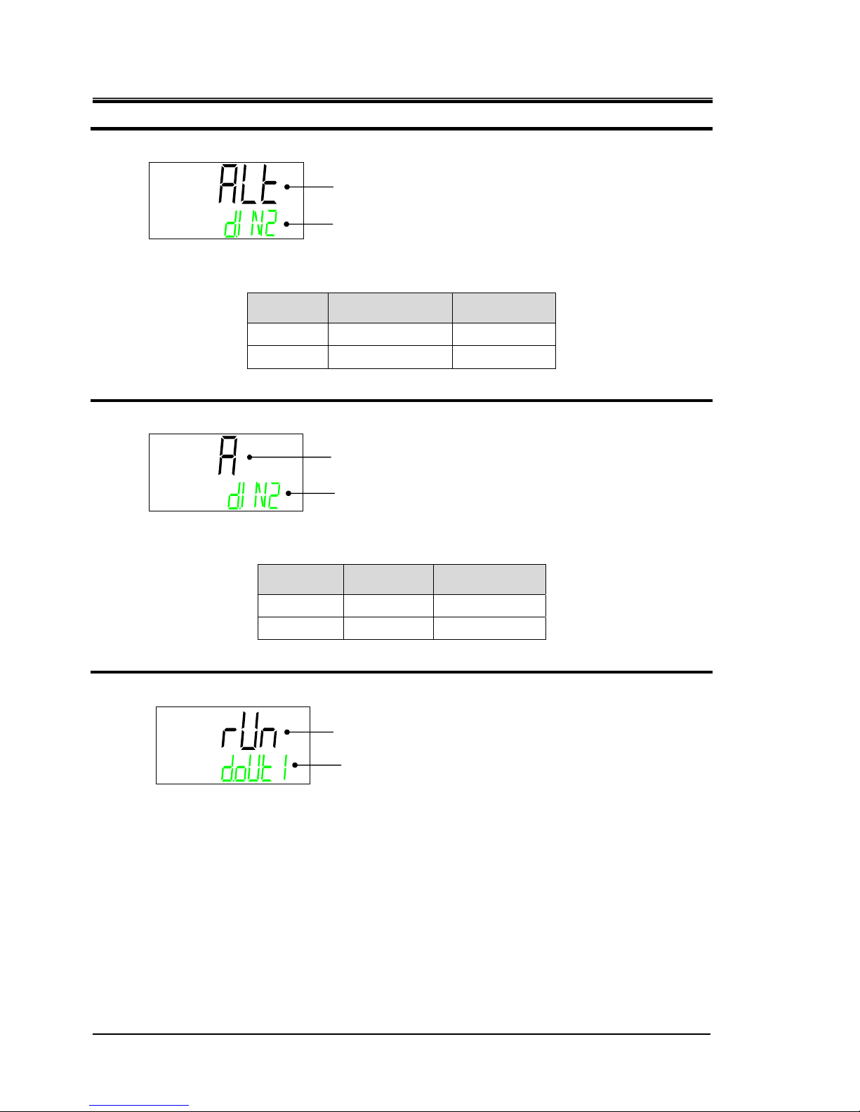
Contact input signal 2 type
6. Press the [▼] key. Displays screen for setting the type of Contact input signal 2.
Displays the type of Contact input signal 2.
Set value Contents
Initial value
ALT
Alternate signal
○
mT
Momentary signal
―
Contact input signal 2 operation
7. Press the [▼] key. Displays screen for setting the operation of the Contact input signal 2.
Select the Contact input signal 2 operation.
Set value Contents
Initial value
A
N.O. type
○
B
N.C. type
―
Contact output signal 1 function
8. Press the [▼] key. Displays setting screen for function of contact output signal 1 .
Displays the function of the Contact output signal 1.
Contact input signal 2 type
DIN2 ⇒ SW ⇒ TYPE(Alternately displayed)
Contact input signal 2 operation
DIN2 ⇒ CON ⇒ TYPE(Alternately displayed)
Contact output signal 1 function
DOUT1 ⇒ SEL(Alternately displayed)
Page 19

HRX-OM-W004
Chapter 2 Contact input/output communication
HRR Series 2.4 Setting and checking
2-7
Set value Explanation
Initial value
(Default setting)
No output signal
―
Operation status signal output
○
Remote status signal output
―
Unused
―
Ready completion (TEMP READY) signal output
―
TEMP OUT (temperature is out of the range) signal output
―
FLT (operation stop) alarm signal output
―
WRN (operation continue alarm) signal output
―
Notice for maintenance signal output
―
Alarm status signal output
―
Pass through signal of the contact input signal 1
―
Pass through signal of the contact input signal 2
―
Selected alarm status signal output
―
Selected notice for maintenance signal output
―
Contact output signal 1 operation
9. Press the [▼] key. Displays screen for setting the operation for the Contact output signal 1.
Select the Contact output signal 1 operation.
Set value Contents
Initial value
A
N.O. type
○
B
N.C. type
―
Contact output signal 1 selected alarm
10. Press the [▼] key. Displays screen for setting the selected alarm for the Contact output
signal 1. The alarm is valid when the “selected alarm status signal output” is active.
Select the alarm No. to be allocated to Contact output signal 1
●Setting range:AL.01~AL.32(Initial value:AL.01)
DOUT ⇒ TYPE(Alternately displayedd)
Contact output signal 1 operation
Contact output signal 1 selected alarm No.
DOUT1 ⇒ ALARM ⇒ CODE(Alternately displayed)
Page 20

HRX-OM-W004
Chapter 2 Contact input/output communication
2.4 Setting and checking HRR Series
2-8
Contact output signal 1 Select maintenance
11. Press the [▼] key. Displays screen for setting the selected maintenance for the Contact
output signal 1. The alarm is valid when the “selected maintenance status signal output”
is active.
Select the maintenance alarm No. to be allocated to Contact output signal 1.
●
Setting range: MT.01 to MT.05 (Initial value: MT.01)
Contact output signal 2 Select function
12. Press the [▼] key. Displays screen for setting the function for the Contact output signal 2.
Displays the function for the Contact output signal 2.
Contact output signal 2 operation
13. Press the [▼] key. Displays screen for setting the operation for the Contact output signal 2
Set value Explanation
Initial value
(Default setting)
No output signal
―
Operation status signal output
―
Remote status signal output
○
Unused
―
Ready completion (TEMP READY) signal output
―
TEMP OUT (temperature is out of the range) signal output
―
FLT (operation stop) alarm signal output
―
WRN (operation continue alarm) signal output
―
Notice for maintenance signal output
―
Alarm status signal output
―
Pass through signal of the contact input signal 1
―
Pass through signal of the contact input signal 2
―
Selected alarm status signal output
―
Selected notice for maintenance signal output
―
Contact output signal 1 Selected maintenance alarm No.
DOUT1 ⇒ MANT ⇒ CODE(Alternately displayed)
Contact output signal 2 Function
DOUT2 ⇒ SEL(Alternately displayed)
DOUT ⇒ SEL(Alternately displayed)
Contact output signal 2 operation
Page 21

HRX-OM-W004
Chapter 2 Contact input/output communication
HRR Series 2.4 Setting and checking
2-9
Select the contact output signal 2 operation.
Set value Contents
Initial value
A
N.O. type
○
B
N.C. type
―
Contact output signal 2 selected alarm
14. Press the [▼] key. Displays screen for setting the selected alarm for the Contact output signal 2.
The alarm is valid when the “selected alarm status signal output” is active.
Select the alarm No. to be assigned to contact output signal 2.
●Setting range:AL.01~AL.32(Initial value:AL.01)
Contact output signal 2 Select maintenance
15. Press the [▼] key. Displays screen for setting the selected maintenance of the Contact
output signal 2. The alarm is valid when the “selected maintenance status signal output” is
selected.
Select the maintenance alarm No. to be allocated to Contact output signal 2.
●
Setting range: MT.01 to MT.05 (Initial value: MT.01)
Contact output signal 3 Select function
16. Press the [▼] key. Displays screen for setting the function of the Contact output signal 3
Select
contact output signal 3 function
Contact output signal 2 selected alarm No.
DOUT2 ⇒ ALARM ⇒ CODE(Alternately displayed)
Contact output signal 2 Selected maintenance alarm No.
DOUT2 ⇒ MANT ⇒ CODE(Alternately displayed)
Contact output signal 3 function
DOUT3 ⇒ SEL(Alternately displayed)
Page 22

HRX-OM-W004
Chapter 2 Contact input/output communication
2.4 Setting and checking HRR Series
2-10
Contact output signal 3 operation
17. Press the [▼] key. Displays screen for setting the operation of the Contact output
signal 3.
Contact output signal 3 operation
Set value Contents
Initial value
A
N.O. type
―
B
N.C. type
○
Contact output signal 3 select alarm
18. Press the [▼] key. Displays screen for setting the selected alarm of Contact output
signal 3. The alarm is valid when the “selected alarm status signal output” is active.
Select the alarm No. to be allocated to Contact output signal 3
●Setting range: AL.01 to AL32 (Initial value: AL01)
Set value Explanation
Initial value
(Default setting)
No output signal
―
Operation status signal output
―
Remote status signal output
―
Unused
―
Ready completion (TEMP READY) signal output
―
TEMP OUT (temperature is out of the range) signal output
―
FLT (operation stop) alarm signal output
―
WRN (operation continue alarm) signal output
―
Notice for maintenance signal output
―
Alarm status signal output
○
Pass through signal of the contact input signal 1
―
Pass through signal of the contact input signal 2
―
Selected alarm status signal output
―
Selected notice for maintenance signal output
―
DOUT ⇒ TYPE(Alternately displayed)
Contact output signal 3 operation
Contact output signal 3 selected alarm No.
DOUT3 ⇒ ALARM ⇒ CODE(Alternately displayed)
Page 23

HRX-OM-W004
Chapter 2 Contact input/output communication
HRR Series 2.4 Setting and checking
2-11
Contact output signal 3 Select maintenance
19. Press the [▼] key. Displays screen for setting the selected maintenance of Contact
output signal 3. The alarm is valid when the “selected maintenance status signal output”
is active.
Select the maintenance alarm No. to be allocated to Contact output signal 3.
●Setting range: MT.01 to MT.05 (Initial value: MT.01)
Contact output signal 3 Selected maintenance alarm No.
DOUT3 ⇒ MANT ⇒ CODE(Alternately displayed)
Page 24

HRX-OM-W004
Chapter 2 Contact input/output communication
2.5 Contact input signal HRR Series
2-12
2.5 Contact input signal
There are two contact input signals. As the default condition, contact input
signal 1 , and contact input signal 2 are not used. The input signals can be
customized depending on the customer’s application.
The combination of possible settings of contact input signals is limited.
Refer to Table 2.5-2 for possible combinations.
Table 2.5-1 Contact input signal type
∗1 N.O.type:normally open (N.O.),N.C.type:normally closed (N.C.).
Table 2.5-2 Combinations of contact input signals
Contact input
1 function
selection
Contact input 2 function selection
OFF STOP SW
OFF ○ × ○
RN.ST ○ × ○
RUN × ○ ×
SW
○ × ○
○:Settable ×:Not settable
Desc ription
Display Description Display
Description
∗
1
Display
Delay
timer of
reading
OFF
detection
N.O.ty p e A - - N.C.type B - - N.O.ty p e A - - N.C.type B - - N.O.ty p e A - - N.C.type B - - N.O.ty p e A - - N.C.type B - - N.O.ty p e A Used Us ed N.C.type B Used Used N.O.ty p e A Used Us ed N.C.type B Used Used N.O.ty p e A - -
○
N.C.type B - - N.O.ty p e A - - N.C.type B - - N.O.ty p e A - - N.C.type B - - N.O.ty p e A - - N.C.type B - - N.O.ty p e A Used Us ed N.C.type B Used Used N.O.ty p e A Used Us ed N.C.type B Used Used N.O.ty p e A - -
○
N.C.type B - - N.O.ty p e A - - N.C.type B - - -
ALT
Mome n tary MT
Without
intput
signal
OFF
Alternate ALT
Mome n tary MT
Contact input signal 2
Stop
signal
STOP
Alternate ALT
Mome n tary MT
External
switch
signal
input
SW
Alternate
Without
intput
signal
OFF
Alternate ALT
Mome n tary MT
ALT
Mome n tary MT
External
switch
signal
input
SW
Alternate ALT
Mome n tary MT
Contact input signal 1
Run/stop
signal
RN.ST
Alternate ALT
Mome n tary MT
Run signal RUN
Alternate
Class of signal Signal configuration Signal operation Timer
Default
setting
Page 25

HRX-OM-W004
Chapter 2 Contact input/output communication
HRR Series 2.5 Contact input signal
2-13
2.5.1 Run/stop・Run・Stop・External switch signal
1) Run/stop signal (Signal type: Alternate)
The product keeps operating while the input signal from the customer is ON.
2) Run/stop signal (Signal type: Momentary)
The state changes when the input signal from the customer goes ON. This signal operates while
the product is stopped, and stops while the product is being operated.
3) Run signal (Signal type: Alternate) /Stop signal (Signal type:Alternate)
Digital input signal 1 is for Run signal(Signal type:Alternate), digital input signal 2 is for stop
signal(Signal type: Alternate). Stop signal becomes valid when both signals are turned ON.
① The product starts operation when the contact input signal 1 is turned ON.
②
The product stops operation when the contact input signal 2 is turned ON.
③
The product starts operation because the contact input signal 1 is turned ON
although the contact input signal 2 is OFF.
OFF
ON
Run
Stop
Product condition
Run/stop signal
(Momentary)
OFF
ON
Run
Stop
Product condition
Run signal
OFF
ON
Stop signal
②
①
③
OFF
ON
Run
Stop
Product condition
Run/stop signal
(Alternate)
Page 26

HRX-OM-W004
Chapter 2 Contact input/output communication
2.5 Contact input signal HRR Series
2-14
4)
Digital input signal 1 is for Run/Stop signal (Signal type: Alternate), digital input signal 2 is for
external switch signal (Signal type: Alternate).Refer to Chapter 2.5.2 for details of the external
switch.
① The product starts operation when the Run/Stop signal from the user is turned
on.
②
It reads the signal of the external switch signal (N.O type) after the time which
has been set for the delay timer of reading.
The factory default setting of the delay timer of reading is 0sec. Refer to 2.4.2 for
setting.
③
When the external switch signal (N.O. type) has been turned off for the time set
for OFF detection timer, it is recognized as OFF.
The factory default setting of the OFF detection timer is 0sec. Refer to 2.4.2 for
setting.
④
AL26 contact input 2 signal detection alarm is generated. The operation of the
product stops.
"Operation stop" is the default setting for AL26. The product can be set to
continue operation or not to detect the alarm. Refer to the “Installation /
Operation” manual for details.
∗The product stops operation when the Run/Stop signal is turned off during
operation. Afterwards, the alarm is not generated even if the external switch
signal is turned off.
2.5.2 Signal of the external switch
This product can be monitored by reading the signal of the
external switch prepared by the customer.
This product generates an alarm and stops operating when a
problem is detected from the external switch.
Monitoring mode can be selected from “continuous monitoring” or
“monitoring only during operation”. Refer to Table 2.5-3.
Select the external switch 1 or 2 or both depending on the
customer’s system. Refer to 2.4.2 for setting method.
The number of monitored external switches depends on the
contact input signal function. Refer to Table 2.5-3
You can set the product to continue operation or not to detect the
alarm. Refer to the “Installation / Operation” manual for details
Table 2.5-3 Monitoring method for contact input
Contact input delay timer for
reading
Monitoring method
0 sec Continuous monitoring
1 to 300 sec Monitor only during operation
OFF
ON
Run
Stop
Product condition
OFF
ON
External switch signal
OFF Detection time
r
③
④①
②
Run/Stop signal
Delay timer of reading
Page 27

HRX-OM-W004
Chapter 2 Contact input/output communication
HRR Series 2.5 Contact input signal
2-15
Run status of this product
Run
Stop
External switch
CLOSE
OPEN
Operation start
Signal reading
start
Delay timer of reading OFF detection timer
Alarm
generation
Operation
stops due to
the alarm.
■Delay timer of reading
If the signal of the external switch prepared by the customer is not closed instantly when the
product is operated, set the delay timer for reading. By setting this timer, the external switch
monitoring starts after the time set by the delay time of reading since the operation start.
“0" is the default setting. Set a time which is suitable for your environment.
Example} When using a flow switch
When operation is started, it takes time for the fluid to reach the piping and the flow
switch to detect the flow. Set the time for the flow switch to start.
■
OFF detection timer
If you do not want the alarm to be generated instantly when the external switch prepared by the
customer is in open status, but instead want the alarm to be generated after the switch has been
open for a specific time (continuous open status), set the OFF detection timer.
This timer enables the alarm to be generated when the time set for OFF detection time passes
after the switch is in OPEN status.The default setting is 0 sec. Set a time which is suitable for your
application.
■
Contact input
N.O type normally open (N.O.) or N.C. type normally closed (N.C.) can be selected for the
external switch. Set the signal which is suitable for the external switch prepared by the customer.
Page 28

HRX-OM-W004
Chapter 2 Contact input/output communication
2.6 Contact output signal HRR Series
2-16
2.6 Contact output signal
There are three contact output signals. As the default setting, contact output
signal 1 is for operating condition (N.O type), contact output signal 2 is for
remote signal (N.O type), and contact output signal 3 is for alarm signal (N.C
type). Refer to Table 2-6-1.Depending on the product condition, contact
output signal is turned on (closed) or turned off (open).
The signals can be customized depending on the customer’s application. The
Table 2.6-2 shows operation of contact output signal.
【Tips】
All contact output signals are turned off (open) when the power is not supplied.
Table2.6-1 Contact output signal (Default setting)
Class of signal Signal configuration
Description Display
Description ∗1
Display
Contact output signal 1 Run status signal RUN
N.O type
A
Contact output signal 2 Remote signal RMT
N.O type
A
Contact output signal 3 Alarm signal ALM
N.C type
B
∗1 N.O.type:normally open (N.O.), N.C.type:normally open (N.O.)
Non generation(not set)
Generation(set)
ON
OFF
Digital output signal
(N.O type)
Product condition
(Set condition)
ON
OFF
Digital output signal
(N.C type)
Page 29

HRX-OM-W004
Chapter 2 Contact input/output communication
HRR Series 2.6 Contact output signal
2-17
Table 2.6-2 Operation of contact output signal
Class of signal
Operation of contact output signal
Display Function Operation
OFF Without output
N.O type Normally, output signal is OFF (open)
N.C type Normally, output signal is ON (close)
RUN Run status signal
N.O type When the product operates, signal turns on.
N.C type When the product operates, signal turns off.
RMT Remote status signal
N.O type
When the product becomes SERIAL REMOTE,
signal turns on.
N.C type When the product becomes LOCAL, signal turns off.
EXT.C
External temperature
control signal
N.O type
Signal is turned on by activating the external
temperature control function.
N.C type
Signal is turned off by activating the external
temperature control function.
RDY
Signal for completion
of preparation (TEMP
READY)
N.O type
When the product becomes completion of preparation
(TEMP READY), signal turns on.
N.C type
When the product becomes completion of preparation
(TEMP READY), signal turns off.
T. OU T
TEMP OUT
(temperature is out of
the range) signal
N.O type
Signal is turned on when the temperature is out of the
range (TEMP OUT).
N.C type
Signal is turned off when the temperature is out of the
range (TEMP OUT).
FLT
Signal for operation
stop alarm
N.O type When operation stop alarm occurs, signal turns on.
N.C type When operation stop alarm occurs, signal turns off.
WRN
Signal for continuing
operation alarm
N.O type When continuing operation alarm occurs,
signal turns on.
N.C type When continuing operation alarm occurs,
signal turns off.
MENT
Maintenance status
signal
N.O type The signal is turned on when the maintenance status
signal is generated.
N.C type The signal is turned off when the maintenance status
signal is generated.
ALM Alarm status signal
N.O type When alarm occurs, signal turns on.
N.C type When alarm occurs, signal turns off.
SW
Pass through signal
of contact input signal
N.O type
Outputs the signal which is input to
the contact input signal.
Input signal is ON Æ Output signal is ON
N.C type
Outputs the reverse of the signal which is
input to the contact input signal.
Input signal is OFF Æ Output signal is ON
ASEL Alarm status signal
N.O type The signal is turned ON when the
selected alarm goes off.
N.C type
The signal is turned OFF when the selected alarm
goes off.
M.SEL
Maintenance status
signal
N.O type
The signal is turned on when the selected
maintenance status signal is generated.
N.C type
The signal is turned off when the selected
maintenance status signal is generated.
Page 30

HRX-OM-W004
Chapter 2 Contact input/output communication
2.6 Contact output signal HRR Series
2-18
Page 31

HRX-OM-W004
Chapter 3 Serial communication
HRR Series 3.1 Precautions wiring communication
3-1
Chapter 3 Serial communication
Serial communication (RS-485/RS232C) enables the remote control of
run/start of the product, temperature setting and details of product condition,
and alarm condition can be obtained.
The operating state of the product (run/stop) and the temperature setting can
be monitored by sending a request message made by the program of the host
computer (e.g. PC).
The communication protocol is MODBUS protocol.
3.1 Precautions wiring communication
○Communication wiring
A communication cable that connects the product and customer system is not
included with the product. Please prepare a cable, referring to 3.2
‘’Connected explanation’’ In order to avoid malfunction, do not connect to any
place other than those shown in 3.2 ‘’Connected explanation’’.
3.2 Connected explanation
Fig 3.2-1 shows the wiring when RS-485 is selected as the communication
standard. Fig 3.2-2 shows the wiring when RS-232C is selected.
A communication cable that connects the product and customer system is not
included with the product. Prepare a cable, referring to
Fig 3.2-1 or Fig 3.2-2.
1
SD+
5
SG
9
SD-
SD+
SD- SG
Terminal
resistance
Master This product
(first slave)
1
SD+
5
SG
9
SD-
This product
(second slave)
1
SD+
5
SG
9
SD-
This product
(31
st
slaves)
Terminal
resistance120Ω
Fig 3.2-1 RS-485 connector connection
【Tips】
・1 master : 1 product, or 1 master: N products.
In the latter case, up to 31 products can be connected.
・Both ends of the communication connection (the end nodes) need to be
connected to the higher level computer.
・The terminal resistance of this product can be set by the operation display
panel. Refer to ‘’3.6.2 Setting and checking’’.
Page 32

HRX-OM-W004
Chapter 3 Serial communication
3.3 Communication specification HRR Series
3-2
Fig 3.2-2 RS-232C connector connection
3.3 Communication specification
Table 3.3-1 Serial communication specification
Item Specification
Connector type (for the product) D-sub9P type Female connector
Standard
Select from EIA RS-485/RS-232C
Circuit type Half duplex Half duplex
Transmission type Start-stop
Protocol
MODBUS terminal
∗1
Terminal resistance
Select from with terminal resistance(120Ω)/Without terminal
resistance
:Default setting
∗1:Refer to Modicon Co. protocol specifications "PI-MBUS-300 Rev.J".
Table 3.2-2 Communication specification of MODBUS communication function
Item Specification
Standard
Select from EIA RS-485/RS-232C
Communication speed
Select from 9600bps/19200bps
Data・bit length
7bit(ASCII) / 8bit(RTU)
Stop・bit length
1bit
Data transfer direction
LSB
Parity Even parity
Letter code
ASCII character string (ASCII) / Binary data(RTU)
Node type
Slave (Controller)
Slave address set range Select from 1 to 32 address
Error check
LRC method
(ASCII) / CRC method (RTU)
:Default setting
2
3
5
RD
SD
SG
2
3
5
RD
SD
SG
Master This product
Page 33

HRX-OM-W004
Chapter 3 Serial communication
HRR Series 3.4 MODBUS communication function
3-3
3.4 MODBUS communication function
MODBUS protocol is a communication protocol developed by Modicon. It is
used to communicate with a PC or PLC.
Register content is read and written by this communication protocol.
This communication has the following features.
・Controls run/stop.
・Sets and reads the circulating fluid set temperature.
・Reads the circulating fluid discharge temperature.
・Reads the condition of the product.
・Reads the alarm generating condition of the product.
Refer to “3.13 Register Map” for the register of the product.
3.5 Precautions for communication
3.5.1 Precautions after wiring and before communication
○Check or set the each communication setting by the operation display
panel.
・The communication specification shall be the customer’s communication
standard.
・The communication mode shall be the SERIAL mode. (When serial mode is
activated, this mode is selected. Refer to Chapter 3.13.11)
Other modes can perform reading, but only SERIAL mode can perform
writing.
○Check or set the communication parameters using the operation display
panel.
Check or set the communication speed so that the product synchronizes with
the host computer (master) prepared by the customer.
○Check the slave address by the operation display panel.
No response is returned when a request message is sent from a slave
address other than those set in the product.
3.5.2 Precautions for communicating
○Allow a suitable interval between requests.
To send request messages in series, wait for 100 msec. or longer after
receiving a response message from the product before sending the next
message.
○Retry (resend request message)
.
The response may not be returned due to noise. If no message is returned
1sec. after sending a request message, resend the request message.
○If necessary send a read request message to check if it was written
correctly.
Page 34

HRX-OM-W004
Chapter 3 Serial communication
3.6 Setting and checking HRR Series
3-4
Message to notify the completion of the process is returned when the action
for the written request message is completed.
Send a read request message to confirm if the setting was written as
requested.
○Setting limit of circulating fluid temperature
When the circulating fluid set temperature is written by communication,
the data is stored in FRAM. When the product restarts, it restarts with the
value which was set before the restart. The number of times it is possible
to overwrite FRAM is limited. Data is only stored in FRAM when it receives
a circulating fluid set temperature which is different from the previous
temperatures. Please check how many times it is possible to overwrite
FRAM, and avoid unnecessary changes of the circulating fluid set
temperature during communication
3.6 Setting and checking
3.6.1 Setting and checking items
The table below explains the setting items of the MODBUS communication
function and the initial values.
Table
3.6-1 Communication setting items
Ini tial
va lu e
Select/setting range
TOP
screen
-
COMM
-
MENU Comm unication setting menu TOP screen
No.1
screen
Serial protocol ASC ASC/RTU PROT Select serial protocol.
No.2
screen
Communication
specification
485 485/232C TYPE Select RS - 485 / RS - 232C.
No.3
screen
RS-485 terminal unit OFF OFF/ON TERM
Select whether RS - 485
terminating resis tance is present or not.
No.4
screen
Slave address 1 1~32
SLV
⇒
ADDR
Set the slave address.
No.5
screen
Communication
speed(bps
)
19.2 9.6/19.2 SPEED Set the com munication s peed.
Display
No.
Item
Display unit
Contents
Upper stage(Whi te
)
Lower stage
(
Green
)
Page 35

HRX-OM-W004
Chapter 3 Serial communication
HRR Series 3.6 Setting and checking
3-5
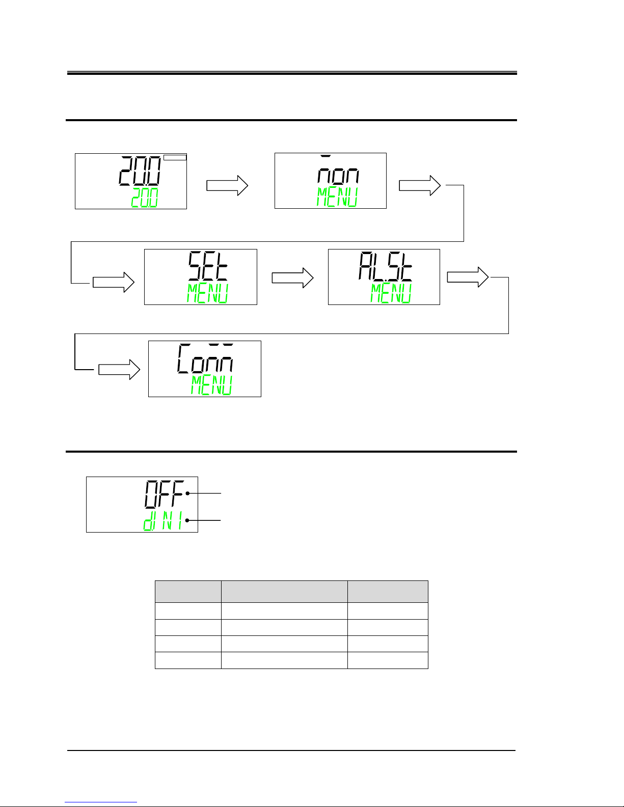
3.6.2 Setting and checking
Communication setting menu TOP screen
1. Displays communication setting menu.
serial protocol
2. Press the [▼] key. Displays screen for setting the serial protocol.
Select communication protocol.
Set value Contents
Initial value
ASC
ASCII mode
○
RTU
RTU mode
―
℃
Main menu
TOP
screen
[MENU] key
Press and hold
(5 seconds)
[MENU]key
[MENU]
key
Alarm setting menu
TOP
screen
Communication setting menu
TOP screen
[MENU]key
[MENU]
key
[MENU]
key
Serial protocol.
Monitor menu
TOP screen
Standard setting
menu TOP screen
Page 36

HRX-OM-W004
Chapter 3 Serial communication
3.6 Setting and checking HRR Series
3-6
Communication specification
3. Press the [▼] key. Displays screen for setting the communication specifications.
Select the communication specification.
Set value Contents
Initial value
485
RS-485
○
232C
RS-232C
―
RS-485 terminal unit
4. Press the [▼] key. Displays screen for setting RS-485 terminal unit.
Select RS-485 terminal unit.
Set value Contents
Initial value
OFF
No terminal
○
On
With terminal
―
Slave addresses
5. Press the [▼] key. Displays screen for setting the slave address.
Sets slave address.
●Setting range: 1 to 32 (Initial value: 1)
Communication specification
RS-485 terminal unit
Slave addresses.
SLV ⇒ ADDR(Alternately displayed)
Page 37

HRX-OM-W004
Chapter 3 Serial communication
HRR Series 3.7 Communication sequence
3-7
Communication speed
6. Press the [▼] key. Displays screen for setting the communication speed.
Selects the communication speed.
Set value Contents
Initial value
9.6
9600 bps
―
19.2
19200 bps
○
3.7 Communication sequence
Starts with a request message from the customer’s system (host), and
finishes with a response message from the product (slave). This product
operates as a slave. It does not send any requests.
●
Positive response
Based on the request message, reads
register/writes register and returns a positive
response.
●
Negative response
Returns a negative message when the
received request message is not normal. Refer
to ‘’3.12 Negative response’’.
●
No response
No response is returned when there is an error in
“slave address specification” or”
Checksum(LRC
/ CRC)
”.
Communication speed
Customer's system
(host)
This product
(slave)
R
e
q
u
e
s
t
m
e
s
s
a
g
e
P
o
s
i
t
i
v
e
r
e
s
p
o
n
s
e
R
e
q
u
e
s
t
m
e
s
s
a
g
e
N
e
g
a
t
i
ve
r
e
s
p
o
n
s
e
R
e
q
u
e
s
t
m
e
s
s
a
g
e
No response
10~200ms
(
R
e
s
p
o
n
s
e
m
e
s
s
a
g
e
)
(
R
e
s
p
o
n
s
e
m
e
s
s
a
g
e
)
Page 38

HRX-OM-W004
Chapter 3 Serial communication
3.8 Message configuration HRR Series
3-8
3.8 Message configuration
3.8.1 Message frame
The message configuration is shown below. The communication of this
product uses 2 transmission modes, ASCII or RTU.
1) ASCII mode frame
For ASCII mode, the message starts with ASCII characters “:”(0X3A) and
ends with “CR/LF”(0X0D,0X0A). A response message will not be returned
unless the request includes [:] and [CR][LF]. This product clears all previously
received code when [:] is received.
Table 3.8-1 ASCII mode message frame
a)Start
b)Slave
Address
c)Function d)Data
e) Checksum
(LRC)
f)End
[:] XX XX XX XX XX
~
XX XX XX [CR] [LF]
a) Start
The start of the message. [:](3Ah) (ASCII)
b) Slave Address
This is a number to identify this product. “1" is the default setting. This can
be changed by the operation display panel.
c) Function(
Refer to “3.9 Function codes”)
Command is assigned.
d) Data
Depending on the function, the address and the number of the register, the
value of reading/writing are assigned.
e) LRC
LRC method
Refer to ‘’3.10.1 LRC(ASCII)’’.
f) END
The end of the message. [CR](0Dh)+[LF](0Ah)
Page 39

HRX-OM-W004
Chapter 3 Serial communication
HRR Series 3.9 Function codes
3-9
2)
RTU mode frame
RTU mode starts from and ends with at least 3.5 characters of silent interval. Silent interval
is indicated by T1-T2-T3-T4.
Table 3.8.2 RTU mode message frame
a)Start
b)Slave
Address
c)Function d)Data
e) Checksum
(CRC)
f)End
T1-T2-T3-T4 XX XX XX ~XX XX XX T1-T2-T3-T4
a) Start
In Modbus RTU mode, message frames are separated by a silent interval
(non-communication time). At least 3.5 characters of silent interval are necessary at the
beginning and the end of the communication frame.
b) Slave Address
This is a number to identify this product. “1" is the default setting. This can be changed by
the operation display panel.
c) Function
Command is assigned.
d) Data
Depending on the function, the address and the number of the register, the value of
reading/writing are assigned.
e) CRC
CRC
method.
Refer to”3.10.2 CRC(RTU)”.
f )End
3.5 characters of silent interval indicates the end of a message.
3.9 Function codes
Table 3.9-1 shows function codes to read or write register. Refer to "3.11
Explanation of function codes ".
Table 3.9-1 Function codes
NO Code Name Function
1 04(04h) read holding registers
Reading multiple registers
2 06(06h) preset single register Writing registers
∗
1
3 16(10h) preset multiple registers
Writing multiple registers
4 23(17h) read/write 4x registers
Reading/writing multiple registers
∗1:Broadcast is not supported.
Page 40

HRX-OM-W004
Chapter 3 Serial communication
3.10 Checksum calculation method HRR Series
3-10
3.10 Checksum calculation method
3.10.1 LRC(ASCII)
LRC checks the content of the message other than [:] of START and [CR][LF]
of END. The sending side calculates and sets. The receiving side calculates
based on the received message, and compares the calculation result with the
received LRC. The received message is deleted if the calculation result and
received LRC do not match.
Add up the byte number of the message consisting of 8 consecutive bits.
The result except the carry (overflow) is converted to 2’s complement.
Calculation example
Example) Change circulating fluid set temperature 25.4 ° C
Sending data 0106000B00FE
○Slave Address:No.1
○Function:No.06
○Writing address:000Bh
○Writing data:00Feh
No
Classification
Contents
calculation result
1
LRC message for
calculation
0106000B00FE
-
2
Calculation
Added for each 8Byte
01h+06h+00h+0Bh+00h+FEh=110
h
10h
3
complement of 2
10h→EFh→F0h
F0h(LRC)
4
Sending message
[:]0106000B00FEF0[CR][LF] -
3.10.2 CRC(RTU)
CRC checks the content of the message. The sending side calculates
the data every 2 bytes (16 bits). The receiving side calculates CRC
based on the received message, and compares the calculation result
with the received CRC. The received message is deleted if the
calculated CRC is different from the received CRC.
Calculation procedure
① Preload “FFFFh” (set 0xFFFF as initial value ).
② Exclusive OR the first byte of the transmitted message with the value in (1).
③ Shift the result of (2) by one bit toward the least significant bit, and fill a zero
into the most significant bit position.
④ If the least significant bit was a 1, exclusive OR the result of (3) with “A001h”.
(Example 1). If the least significant bit was a 0, no exclusive OR takes place.
⑤ Repeat (3) to (5) until eight shifts have been performed.S
⑥ After eight shifts, exclusive OR the result of (5) with the next 1-byte (2nd.
byte).
⑦ The processes (3) to (6) are repeated for all the remaining bytes of the
message.
⑧ The 2-byte data of the result of (7) is the CRC value.
Page 41

HRX-OM-W004
Chapter 3 Serial communication
HRR Series 3.10 Checksum calculation method
3-11
(Example 1) The least significant bit was a 1.
(Example 2) The least significant bit was a 0.
Calculation example
Example) Change circulating fluid set temperature 25.4 ° C
Sending data 0106000B00FE
○Slave Address : No.1
○Function:No.06
○Writing address:000Bh
○Writing data:00FEh
Aata No. 1st
value
2nd
value
3rd
value
4th
value
5th
value
6th
value
Data
contents
0001h 0006h 0000h 000Bh 0000h 00FEh
0 00 00000
0
00 0 0 000 0
…
Add 0 to the top
If it is 0, do not ExOR
…
1 bit shift in the lowest direction
0000 0001
0 000 00001
…
…
1 bit shift in the lowest direction
Add 0 to the top
Execute ExOR if 1
Page 42

HRX-OM-W004
Chapter 3 Serial communication
3.11 Explanation of function codes HRR Series
3-12
No
Classification
Contents Result
1
CRC
message for
calculation
0106000B00FE -
2
Calculation
Perform (1) to (4) for the 1st value (0001h) and then,
perform (5).
807Eh
3
Perform (6) for 2nd value (0006h) and then, perform
(5).
2280h
4
Perform (6) for 3rd. value (0000h) and then, perform
(5).
A023h
5
Perform (6) for 4th value (000Bh) and then, perform
(5).
1EA0h
6
Perform (6) for 5th value (0000h) and then, perform
(5).
781Eh
7
Perform (6) for 6th value (00FEh) and then, perform
(5).
8879h
(CRC)
8
Addition to the
sent message
0106000B00FE7988∗1 -
∗1 When incorporating it into the message, set it in order of low byte and high byte.
3.11 Explanation of function codes
3.11.1 Function code:04 Reading multiple registers
Register data of assigned points from assigned address is read.
■
Communication example
○Slave Address : No.1
○
Read seven consecutive data from register 0000h.
(
Read circulating fluid discharge temperature、circulating fluid flow rate、circulating fluid
discharge pressure
、 electric conductivity of the circulating fluid 、 status address
information
、alarm information)
Request message 010400000007
Field name
Example
(HEX)
ASCII mode
character data
RTU mode
binary data
Header - “:”
None
Slave Address 0x01
“0”,“1” 0x01
Function 0x04 “0”,“4” 0x04
Head address of specified register 0x0000 “0”,“0”,“0”,“0” 0x00,0x00
Quantity of register to read 0x0007 “0”,“0”,“0”,“7” 0x00,0x07
Checksum ASCII:LRC RTU:CRC -
“F”,”4” 0xB1,0xC8
Trailer
-
CR/LF
None
To ta l
quantity of byte
17 8
Page 43

HRX-OM-W004
Chapter 3 Serial communication
HRR Series 3.11 Explanation of function codes
3-13
Response message 01040E00D40000000D0000020100000000
Field name
Example
(HEX)
ASCII mode
character data
RTU mode
binary data
Header - “:”
None
Slave Address
0x01
“0”,“1” 0x01
Function
0x04
“0”,“4” 0x04
Quantity of bytes to read 0x0E
“0”,“E” 0x0E
Information of 0000h(Circulating fluid
discharge temperature
)
0x00D4
“0”,“0”,“D”,“4” 0x00,0xD4
Information of 0001h(Circulating fluid
flow rate
)
0x0000
“0”,“0”,“0”,“0” 0x00,0x00
Information of 0002h(Circulating fluid
discharge pressure
)
0x000D
“0”,“0”,“0”,“D” 0x00,0x0D
Information of 0003h(Electric
conductivity of the circulating fluid
)
0x0000
“0”,“0”,“0”, “0” 0x00,0x00
Information of 0004h (Status flag 1) 0x0201
“0”,“2”,“0”,“1” 0x02,0x01
Information of 0005h (Alarm flag 1) 0x0000
“0”,“0”,“0”,“0” 0x00,0x00
Information of 0006h (Alarm flag 2) 0x0000
“0”,“0”,“0”,“0” 0x00,0x00
Checksum ASCII:LRC RTU:CRC - “0”,”9” 0xF8,0x80
Trailer
- CR/LF
None
To ta l
quantity of byte
39 19
3.11.2 Function code:06 Writing registers
Write data to assigned address.
■Communication example
○Slave Address : No.1
○
Write data to register 000Ch
(Commands to run)
Request message 0106000C0001
Field name
Example
(HEX)
ASCII mode
character data
RTU mode
binary data
Header - “:”
None
Slave Address
0x01
“0”,“1”
0x01
Function 0x06 “0”,“6” 0x06
Head address of specified register 0x000C “0”,“0”,“0”,“C” 0x00,0x0C
Information written to 000Ch
(Stop flag)
0x0001 “0”,“0”,“0”,“1” 0x00,0x01
Checksum ASCII:LRC RTU:CRC
- “E”,”C” 0x88,0x09
Trailer
- CR/LF
None
-
To ta l
quantity of byte
17 8
Page 44

HRX-OM-W004
Chapter 3 Serial communication
3.11 Explanation of function codes HRR Series
3-14
Response message 0106000C0001
Field name
Example
(HEX)
ASCII mode
character data
RTU mode
binary data
Header - “:”
None
Slave Address
0x01
“0”,“1” 0x01
Function
0x06
“0”,“6” 0x06
Address of register to write 0x000C
“0”, “0”,“0”,“C” 0x00,0x0C
Information of register to write 0x0001
“0”,“0”,“0”,“1” 0x00,0x01
Checksum ASCII:LRC RTU:CRC - “E”,“C” 0x88,0x09
Trailer
- CR/LF
None
To ta l
quantity of byte
17 8
3.11.3 Function code:16 Writing multiple registers
Register content of assigned points of assigned address is written.
■ Communication example
○Slave Address No.1
○
Write two consecutive data from register 000Bh.
(
Commands to change of circulating fluid set temperature <34.9 oC > and run.)
Request message 0110000B000204015D0001
Field name
Example
(HEX)
ASCII mode
character data
RTU mode
binary data
Header - “:”
None
Slave Address 0x01
“0”,“1”
0x01
Function 0x10 “1”,“0”
0x10
Head address of specified register 0x000B “0”,“0”,“0”,“B”
0x00,0x0B
Quantity of register to write
0x0002 “0”,“0”,“0”,“2”
0x00,0x02
Quantity of byte to read
0x04 “0”,“4”
0x04
Information written to 000Bh
(Circulating fluid set temperature)
0x015D “0”,“1”,“5”,“D”
0x01,0x5D
Information written to 000Ch
(Stop flag)
0x0001 “0”,“0”,“0”,“1”
0x00,0x01
Checksum ASCII:LRC RTU:CRC - “7”,”F”
0xE3,0xF2
Trailer
- CR/LF
None
-
To ta l
quantity of byte
27
13
Page 45

HRX-OM-W004
Chapter 3 Serial communication
HRR Series 3.11 Explanation of function codes
3-15
Response message 0110000B0002
Field name
Example
(HEX)
ASCII mode
character data
RTU mode
binary data
Header - “:”
None
Slave Address
0x01
“0”,“1” 0x01
Function
0x10
“1”,“0” 0x10
Head address of register to write 0x000B
“0”,“0”,“0”,“B” 0x00,0x0B
Quantity of register to write 0x0002
“0”,“0”,“0”,“2” 0x00,0x02
Checksum ASCII:LRC
RTU:CRC
- “E”,”2” 0x30,0x0A
Trailer
- CR/LF
None
To ta l
quantity of byte
17 8
3.11.4 Function code:23 Reading/writing multiple registers
Register content of assigned points of assigned address is read. Write the
register data from the specified address with specified points simultaneously.
■ Communication example
○Slave Address:No.1
○
Read three consecutive data from register 0004h, and write two consecutive data from
register 000Bh.
(Command to change the circulating fluid set temperature to <15.5oC>, and read status
and alarm information.)
Request message 011700040003000B000204009B0001
Field name
Example
(HEX)
ASCII mode
character data
RTU mode
binary data
Header - “:”
None
Slave Address
0x01
“0”,“1”
0x01
Function
0x17 “1”,“7” 0x17
Head address of specified register
0x0004 “0”,“0”,“0”“4” 0x00,0x04
Quantity of register to read
0x0003 “0”,“0”,“0”“3” 0x00,0x03
Head address of specified register
0x000B “0”,“0”,“0”,“B” 0x00,0x0B
Quantity of register to write
0x0002 “0”,“0”,“0”,“2” 0x00,0x02
Quantity of byte to write
0x04 “0”,“4” 0x04
Information written to 000Bh
(Circulating fluid set temperature)
0x009B “0”,“0”,“9”,“B” 0x00,0x9B
Information written to 000Ch (Stop
flag)
0x0001 “0”,“0”,“0”,“1” 0x00,0x01
Checksum ASCII:LRC
RTU:CRC
- “3”,”4” 0x96,0xD6
Trailer
- CR/LF
None
-
To ta l
quantity of byte
35 17
Page 46

HRX-OM-W004
Chapter 3 Serial communication
3.12 Negative response HRR Series
3-16
Response message 011706000000000000
Field name
Example
(HEX)
ASCII mode
character data
RTU mode
binary data
Header - “:”
None
Slave Address
0x01
“0”,“1” 0x01
Function
0x17
“1”,“7” 0x17
Quantity of bytes to read 0x06
“0”,“6” 0x06
Information of 0004h (Status flag 1)
0x0000
“0”,“0”,“0”,“0” 0x00,0x00
Information of 0005h (Alarm flag 1)
0x0000
“0”,“0”,“0”,“0” 0x00,0x00
Information of 0006h (Alarm flag 2)
0x0000
“0”,“0”,“0”,“0” 0x00,0x00
Checksum ASCII:LRC RTU:CRC - “E”,“2” 0x21,0x8A
Trailer - CR/LF
None
To ta l
quantity of byte
23 11
3.12 Negative response
A negative response is returned when the following request message is
received.
1) When unspecified function code is used.
2) An address out of range is specified.
3) The data field is not normal.
Negative response message (Slave to Master)
1) Negative acknowledgment message frame in ASCII mode.
Start
Slave
Address
1)Function
2)Error
Code
LRC End
[:] XX XX XX XX XX XX XX XX [CR] [LF]
2)
Negative acknowledgment message frame in RTU.
Start
Slave
Address
1)Function
2)Error
Code
CRC End
T1-T2-T3-T4
∗1
XX XX XX XX XX XX T1-T2-T3-T4
∗1
∗1 Silent interval for 3.5 characters
1) Function
Assign the value consisting of the request function code (hexadecimal
value) plus 80h.
Example 1) ASCII mode
Received function code: “04”(0000 0100)” ASCII code 30h, 34h
Abnormal function code: ”84”(1000 0100)” ASCII code 38h, 34h
Example 2) RTU mode
Receive function code: "04" (0000 0100)
Abnormal function code: "84" (1000 0100)
Page 47

HRX-OM-W004
Chapter 3 Serial communication
HRR Series 3.12 Negative response
3-17
2) Error Code
Assign error code below.
01 : Function code of a command is outside the standard
02 : The specified address of register is outside the range.
03 : Data field of a command is not normal.
■
Communication example
○Slave Address: No 1
○
Read seven consecutive data from register 0100h which is out of range.
Request message 010401000007
Field name
Example
(HEX)
ASCII mode
character data
RTU mode
binary data
Header - “:”
None
Slave Address
0x01 “0”,“1” 0x01
Function 0x04 “0”,“4” 0x04
Head address of register out of range
0x0100 “0”,“1”,“0”,“0” 0x01,0x00
Quantity of register to read
0x0007 “0”,“0”,“0”,“7” 0x00,0x07
Checksum ASCII:LRC RTU:CRC
- “F”,”3” 0xB0,0x34
Trailer
- CR/LF
None
-
To ta l
quantity of byte
16 8
Response message 018402
Field name
Example
(HEX)
ASCII mode
character data
RTU mode
binary data
Header
- “:”
None
Slave Address
0x01
“0”,“1” 0x01
Function (03h+80h) 0x84
“8”,“4” 0x84
Error Code
(Specified register address
is out of range.)
0x02
“0”,“2” 0x02
Checksum ASCII:LRC RTU:CRC
- “7”,“9” 0xC2,0xC1
Trailer
- CR/LF
None
To ta l
quantity of byte
11 5
Page 48

HRX-OM-W004
Chapter 3 Serial communication
3.13 Register Map HRR Series
3-18
3.13 Register Map
Address
Bit Format
R/W
15 14 13 12 11 10 9 8 7 6 5 4 3 2 1 0
0000h
Circulating fluid discharge temperature
-327.6 to 327.6℃ = F334h to 0CCCh(0.1℃/dig)
(Refer to 3.13.1 Circulating fluid discharge temperature)
R
0001h
Circulating fluid flow rate
-3276.8 to 3276.7LPM = 8000h to 7FFFh(0.1LPM/dig)
(Refer to 3.13.2
Circulating fluid flow rate)
0002h
Circulating fluid discharge pressure
-32.768 to 32.767MPa = 8000h to 7FFFh(0.0001MPa/dig)
(Refer to 3.13.3 Circulating fluid discharge pressure)
0003h
Electric conductivity of the circulating fluid
–3276.8 to 3276.7μS/cm = 8000 to 7FFFh (0.1μS/cm/dig)
(Refer to 3.13.4 Electric conductivity of the circulating fluid)
0004h Status flag 1 (Refer to 3.13.5 Status flag 1)
0005h Alarm flag 1 (Refer to 3.13.6 Alarm flag)
0006h Alarm flag 2 (Refer to 3.13.6 Alarm flag)
0007h None
0008h Data instruction information 2 ∗1 Data instruction information 1 ∗1
0009h
Data display 1(Refer to 3.13.8 Data display)
000Ah Data display 2(Refer to 3.13.8 Data display)
000Bh
Circulating fluid set temperature
-3276.8 to 3276.7℃ = 8000h to 7FFFh (0.1℃/dig)
(Refer to 3.13.9 Circulating fluid set temperature)
R/W
000Ch None ∗3
Reserv
ed
No
ne
∗2
000Dh None
000Eh None
000Fh Data instruction 2 ∗4 Data instruction1 ∗4
∗1 Data instruction information (Refer to 3.13.7 Data instruction information)
∗2 Operation Start Command (Refer to 3.13.10 Operation Start Command)
∗3 Serial remote instruction (Refer to 3.13.11 Serial remote instruction)
∗4
Data instruction (Refer to 3.13.12 Data instruction)
Page 49

HRX-OM-W004
Chapter 3 Serial communication
HRR Series 3.13 Register Map
3-19
3.13.1 Circulating fluid discharge temperature
Read the circulating fluid discharge temperature in the selected temperature
unit (°C or °F). Read the circulating fluid discharge temperature which is
displayed on the operation display panel. (Offset temperature is displayed if
offset function is set).
3.13.2 Circulating fluid flow rate
Read the circulating fluid flow rate in the selected pressure unit.
3.13.3 Circulating fluid discharge pressur
Read the circulating fluid discharge pressure in the selected pressure unit.
3.13.4 Electric conductivity of the circulating fluid
Electric conductivity of the circulating fluid is informed.
0 is announced when option-DM is not selected.
3.13.5 Status flag
The status of the product is read by the following assignment.
Status flag
Name Status flag
Bit 15 14 13 12 11 10 9 8 7 6 5 4 3 2 1 0
Bit Name Explanation
0
Run flag
Run status 0= Stop 1= Run
1
Operation stop alarm flag
Operation stop alarm given off status
0= Not occurred 1= Operation stop alarm given off
2
Operation continued alarm
flag
Operation continued alarm given off status
0= Not occurred 1= Operation continued alarm
given off
3
Unused
―
4
Unused
―
5
Remote status flag
Remote status
0= Other than SERIAL mode 1= SERIAL mode
6
Unused
―
7
Unused
―
8
Unused
―
9
Completion of preparation
(TEMP READY) flag
Completion of preparation (TEMP READY) status
0= Condition isn’t formed 1= Condition is formed
10
Temperature range
monitoring
(TEMP OUT)flag
Temperature range monitoring(TEMP OUT) status
0= Condition is not established
1=Condition is established
11
Notice for maintenance
Notice for maintenance status
0 = Not generated 1 = Generated
12
Unused
―
13
Unused
―
14
Unused
―
15
Unused
―
Page 50

HRX-OM-W004
Chapter 3 Serial communication
3.13 Register Map HRR Series
3-20
3.13.6 Alarm flag
Each type of alarm which occurs in the product is read with the following
assignment.
Name Alarm flag 1
Bit 15 14 13 12 11 10 9 8 7 6 5 4 3 2 1 0
Name Alarm flag 2
Bit 15 14 13 12 11 10 9 8 7 6 5 4 3 2 1 0
Bit Name Explanation
Alarm flag 1
0 AL01 : Tank level drop abnormality
Alarm given off status
0= Not occurred
1= Occurred
1 AL02 : Low level in tank
2 Unused
3 AL04 : Water leakage
4 Unused
5 Unused
6 Unused
7 Unused
8 AL09 : Circulating fluid discharge pressure rise
9 AL10 : Flow rate decreased
10 AL11 : Ambient temperature is out of the range
11 AL12 : Electric conductivity increase
12 AL13 : NOT TEMP READY
13 AL14 : Circulating fluid temperature increase
14 AL15 : Circulating fluid temperature decrease
15 Unused
Alarm flag 2
0 AL17 : Low flow rate
1 AL18 : High circulating fluid discharge temp.
2 AL19 : High circulating fluid return temp.
3 Unused
4 AL21 : High circulating fluid discharge pressure
5 Unused
6 Unused
7 AL24 : Memory error
8 AL25 : Contact input1
9 AL26 : Signal detection
10 AL27 : Contact input 2
11 AL28 : Signal detection
12 AL29 : Forced stop
13 AL30 : Notice for maintenance
14 AL31 : Communication error
15 AL32 : Compressor circuit error
Page 51

HRX-OM-W004
Chapter 3 Serial communication
HRR Series 3.13 Register Map
3-21
3.13.7 Data instruction information
Instruction information set in the Data instruction is displayed. Refer to
3.13.12 "Data Instruction” for details.
3.13.8 Data display
The content selected for the Data instruction is displayed in Data display 1
and Data display 2. Table below shows the data type which can be displayed
and the range.
No.
Item Range
1 TH1(circulating fluid return temp.)
-327.6~327.6℃ = F334h~0CCCh(0.1℃/dig)
3.13.9 Circulating fluid set temperature
The circulating fluid set temperature can be set during SERIAL mode.
If the temperature exceeds the upper limit of the circulating fluid set
temperature range, the circulating fluid set temperature is changed to the
upper limit value. If it is lower than the lower limit, the circulating fluid set
temperature is changed to the lower limit value.
3.13.10 Operation Start Command
The operation can be controlled by sending the operation start command
during SERIAL mode.
0=Run stop
1=Run start
3.13.11 Serial remote instruction
Operation mode can be switched to SERIAL mode during LOCAL mode or
DIO mode by enabling/ disabling the communication mode and serial
communication mode.
0:
None, 1:LOCAL/DIO mode, 3:SERIAL mode
Example 1) Switch the SERIAL mode
Enable serial communication mode with communication mode
switching enabled. Set a 1 to the 4th and 5th bit of address 00C0h.
Example 2) Switch the LOCAL/ DIO mode
Disables serial communication mode and enables the
communication mode. Set a 1 to the 4th bit and set a 0 to the 5th bit
of address 00C0h.
4th bit 0= Communication mode cannot be switched
1= Communication mode can be switched
5th bit
0=Serial communication mode disabled
1=
Serial communication mode enabled
Page 52

HRX-OM-W004
Chapter 3 Serial communication
3.13 Register Map HRR Series
3-22
3.13.12 Data instruction
Selected data is displayed in the address 0009h (Data display 1) and
0010h (Data display 2) by setting the Data instruction.
Data types which can be displayed are shown below. Data display 1
shows the data instructed by the Data instruction 1 (instructed by low
order 8 bits).
Data display 2 shows the data instructed by the Data instruction 2
(instructed by high order 8 bits).
MSB LSB
15 14 13 12 11 10 9 8 7 6 5 4 3 2 1 0
Data instruction 2 Data instruction 1
Bit 7 to 0:Data instruction 1
0:
None
1:TH1(circulating fluid return temp)
Bit 15 to 8:
Data instruction 2
0:
None
1:TH1(circulating fluid return temp)
Example)
Display the circulating fluid return temperature
When 0001h is entered to the address 000F, the circulating fluid return
temperature is displayed in 0009h.
■
Communication example
○When reading the circulating fluid return temp to the data display 1
○Slave Address:No.1
○Function code 23: One data of 0009h is read and one data is written to 000Fh
(Set circulating fluid return temperature to data instruction 1. Read circulating fluid
return temp of data display 1.)
Request message 011700090001000F0001020001
Field name
Example
(HEX)
ASCII mode
character data
RTU mode
binary data
Header
- “:” None
Slave Address
0x01 “0”,“1” 0x01
Function
0x17 “1”,“7” 0x17
Head address of specified register
0x0009 “0”,“0”,“0”“9” 0x00,0x09
Head address of specified register
0x0001 “0”,“0”,“0”“1” 0x00,0x01
Head address of specified register
0x000F “0”,“0”,“0”,“F” 0x00,0x0F
Quantity of register to write
0x0001 “0”,“0”,“0”,“1” 0x00,0x01
Quantity of byte to read
0x02 “0”,“2” 0x02
Information written to 000Fh
(Data instruction)
0x0001 “0”,“0”,“0”,“1” 0x00,0x01
Checksum ASCII:LRC RTU:CRC
- “C”,”B” 0x45,0xBE
Trailer
- CR/LF None
- Total
quantity of byte
31 15
Page 53

HRX-OM-W004
Chapter 3 Serial communication
HRR Series 3.13 Register Map
3-23
Response message 01170200C8
Field name
Example
(HEX)
ASCII mode
character data
RTU mode
binary data
Header - “:”
None
Slave Address
0x01
“0”,“1” 0x01
Function
0x17
“1”,“7” 0x17
Quantity of byte to read 0x02
“0”,“2” 0x02
Information of 0009
(TH1(Circulating fluid return temp))
0x00C8
“0”,“0”,“C”,“8” 0x00,0xC8
Checksum ASCII:LRC RTU:CRC - “1”,“E” 0xBC,0x22
Trailer - CR/LF
None
To ta l
quantity of byte
15 7
Page 54

HRX-OM-W004
Chapter 3 Serial communication
3.13 Register Map HRR Series
3-24
Page 55

HRX-OM-W004
Chapter 4 Communication alarm function
HRR Series 4.1 Communication alarm occurs
4-1
Chapter 4 Communication alarm
function
Monitors whether the serial communication is sent/received properly between
the product and the customer’s device. This feature is only valid when the
communication mode is set to SERIAL mode.
Abnormal signals or disconnection of the communication cable can be notified
immediately by setting the alarm function to match the interval at which
messages are sent from the customer device. When the communication is
restored, the alarm is automatically reset.
Do not use this function when the customer device does not send messages
regularly.
4.1 Communication alarm occurs
Fig 4.1-1 shows when an alarm occurs. Refer to 4.3 ‘’Setting and checking’’
for the setting method.
●
Changing of communication error
Operation continues when an alarm occurs.
●
Time for monitoring the communication error
180 sec
When the customer's device is sending messages every 60sec, if the
communication cable is disconnected and no message is received for 180sec,
the product generates AL29 communication error alarm to notify the error.
This productYour system
Write or read
Write or read
60 sec.
60 sec.
60 sec.
60 sec.
Broken
wire
o
r
coming
of
f
Passage o
f
180 sec.
Excess at no
communicatio
n monitoring
time.
A
L29 Communication
error is generated.
Operation continues
Monitoring
time
Monitoring
time
Fig
4.1-1 Communication alarm example
Page 56

HRX-OM-W004
Chapter 4 Communication alarm function
4.2 Communication alarm reset HRR Series
4-2
4.2 Communication alarm reset
When AL29 communication error has been generated, the alarm is
automatically reset when the disconnection of the communication cable is
fixed, and the message from the customer is received. If operation is set to
stop when a communication alarm occurs, restart the operation if necessary.
This productYour system
Write or read
Write or read
60 sec.
60 sec.
60 sec.
Broken
wire
o
r
coming
of
f
A
L29 Communication
error is generated.
Monitoring
time
Monitoring
time
Normal
connection
Communication erro
r
automatic restoration
Write or read
60 sec.
:
:
Fig 4.2-1 Communication alarm restoration example
4.3 Setting and checking
4.3.1 Setting and checking items
The table below explains the setting items of the communication alarm
function and default values.
Table
4.3-1 Communication error setting item
Initial value Select/setting range
TOP
screen
-
AL.ST
-
MENU
--
No.24
screen
Changing of「AL29
:
Communication error alarm
」
WRN OFF/WRN/FLT COMM⇒ALARM
-
Set the operation when "AL29: Communication
error alarm"is generated.
No.25
screen
Detection time for 「AL29
:
Communication error alarm
」
30 1~600 COMM⇒TIME SEC
Set the alarm monitoring time when"AL29:
Communication error alarm"is generated.Alarm
signal is generated when the monitoring time is
exceeded.
Screen
No.
Ite m
Display unit
Unit
display
ContentsUpper stage(White
)
Lower stage
(
Green
)
Page 57

HRX-OM-W004
Chapter 4 Communication alarm function
HRR Series 4.3 Setting and checking
4-3
4.3.2 Setting and checking
Alarm setting menu Top page
1. Displays Communication Setting Menu.
Swiching of communication error alarm
2. Press the [▼] key. Displays screen for setting the communication error alarm
operation.
Operation for alarm AL29: Communication error can be selected.
Set value Contents
Initial value
OFF
Alarm is not generated.
―
WRN
Operation of this product will continue when the
alarm occurs.
○
FLT
Operation of this product will stop when the alarm
occurs.
―
℃
Main menu
TOP
screen
Monitor Menu
TOP
screen
[MENU]key
Standard setting menu
TOP
screen
[MENU]key
Alarm setting menu
TOP screen
Operation for communication error alarm
COMM ⇒ ALARM(Alternately displayed)
Press [MENU]
and hold for 5
seconds.
[MENU]key
Page 58

HRX-OM-W004
Chapter 4 Communication alarm function
4.3 Setting and checking HRR Series
4-4
Communication error alarm detection time
3. Press the [▼] key. Displays screen for setting the communication error alarm detection
time.
Time (sec.) to generate alarm AL29: Communication error can be changed.
●
Setting range: 1 to 600sec. (Initial value: 30sec.)
SEC
Communication error alarm detection time
COMM ⇒ TIME(Alternately displayed)
Page 59

Page 60

Revision
Rev A:November.2018
4-14-1, Sotokanda, Chiyoda-ku, Tokyo 101-0021 JAPAN
Tel: + 81 3 5207 8249 Fax: +81 3 5298 5362
URL http://www.smcworld.com
Note: Specifications are subject to change without prior notice and any obligation on the part of the manufacturer.
© 2018 SMC Corporation All Rights Reserved
 Loading...