

SMC Networks HRR024-A*-20, HRR018-A*-20, HRR012-W*-20, HRR030-A*-20, HRR018-W*-20 Operating Manual
...Page 1
HRX-OM-W002-A
Original Instructions
Thermo-chiller
HRR012-A-20-
HRR018-A-20-
HRR024-A-20-
HRR030-A-20-
HRR012-W-20-
HRR018-W-20-
HRR024-W-20-
HRR030-W-20-
Operation Manual
Installation ・ Operation
Keep this manual available whenever necessary
© 2018 SMC CORPORATION All Rights Reserved
Page 2

Note: This manual is subject to possible change without prior notice.
To the users
Thank you for purchasing SMC’s Thermo chiller (hereinafter referred to as the “product”).
For safety and long life of the product, be sure to read this operation manual (hereinafter referred to as the
“manual”) and clearly understand the contents.
● Be sure to read and follow all instructions noted with “Warning” or “Caution” in this manual.
● This manual is intended to explain the installation and operation of the product. Only people who
understand the basic operation of the product through this manual or who perform installation and
operation of or have basic knowledge about industrial machines are allowed to work on the product.
● This manual and other documents attached to the product do not constitute a contract, and will not
affect any existing agreements or commitments.
● It is strictly prohibited to copy this manual entirely or partially for the use by a third party without prior
permission from SMC.
Page 3

HRX-OM-W002-A
Contents
Contents
Chapter 1 Safety Instructions ........................................................... 1-1
1.1 Before using the product ........................................................................................ 1-1
1.2 Reading the Manual ................................................................................................ 1-1
1.3 Hazards .................................................................................................................... 1-2
1.3.1 Level of hazards ................................................................................................................... 1-2
1.3.2 Definition of “Serious injury” and “Minor injury” .................................................................... 1-2
1.4 Product Label .......................................................................................................... 1-3
1.5 Safety Measures ...................................................................................................... 1-4
1.5.1 Safety instructions for use .................................................................................................... 1-4
1.5.2 Personal protective equipment ............................................................................................ 1-4
1.6 Emergency Measures.............................................................................................. 1-5
1.7 Waste Disposal ........................................................................................................ 1-6
1.7.1 Disposal of refrigerant and compressor oil .......................................................................... 1-6
1.7.2 Disposal of product .............................................................................................................. 1-6
1.8 Material Safety Data Sheet (MSDS) ........................................................................ 1-7
Chapter 2 Name and Function of Parts ............................................ 2-1
2.1 Model Number of Product ....................................................................................... 2-1
2.1.1 Air-cooled refrigerator type................................................................................................... 2-1
2.1.2 Water-cooled refrigerator type ............................................................................................. 2-2
2.2 Name and Function of Parts ................................................................................... 2-3
2.2.1 HRR-A-20- (Air cooled type) ........................................................................................... 2-3
2.2.2 HRR-W-20-U(Water cooled type) ................................................................................... 2-4
2.3 Function of Parts ..................................................................................................... 2-5
2.4 Operation display panel .......................................................................................... 2-6
Chapter 3 Transport and Setting Up ................................................. 3-1
3.1 Transport.................................................................................................................. 3-1
3.2 Installation ............................................................................................................... 3-2
3.2.1 Environment ......................................................................................................................... 3-2
3.2.2 Location ................................................................................................................................ 3-4
3.2.3 Installation and Maintenance Space .................................................................................... 3-6
3.3 Installation ............................................................................................................... 3-7
3.3.1 Mounting............................................................................................................................... 3-7
3.3.2 Electrical wiring .................................................................................................................... 3-8
3.3.3 Preparation and wiring of power supply cable ...................................................................3-10
3.3.4 Contact input/output communication wiring .......................................................................3-12
3.3.5 Wiring of run/stop signal input and remote signal input .....................................................3-14
3.3.6 Wiring of contact output signal ...........................................................................................3-15
3.3.7 RS-485 communication wiring ...........................................................................................3-16
3.3.8 RS-232C communication wiring .........................................................................................3-18
3.4 Piping ..................................................................................................................... 3-19
3.5 Fill of circulating fluid ........................................................................................... 3-22
HRR Series
Page 4

HRX-OM-W002-A
Contents
Chapter 4 Starting the Product ......................................................... 4-1
4.1 Before Starting ......................................................................................................... 4-1
4.2 Starting and Stopping .............................................................................................. 4-2
4.2.1 Operation ............................................................................................................................. 4-2
4.2.2 Operation restart when alarm is generated ......................................................................... 4-3
4.2.3 Stopping the product ........................................................................................................... 4-5
4.3 Adjustment of bypass valve .................................................................................... 4-6
4.4 Check items after starting ................................ ....................................................... 4-6
Chapter 5 Display and Setting of Various Functions ...................... 5-1
5.1 List of Functions ...................................................................................................... 5-1
5.2 Function.................................................................................................................... 5-2
5.2.1 Key operations ..................................................................................................................... 5-2
5.3 List of parameters .................................................................................................... 5-6
5.3.1 Main Menu ........................................................................................................................... 5-6
5.3.2 Alarm display menu ............................................................................................................. 5-6
5.3.3 Notice for maintenance Menu ............................................................................................. 5-6
5.3.4 Monitor Menu ....................................................................................................................... 5-7
5.3.5 Standard setting menu ........................................................................................................ 5-8
5.3.6 Alarm Setting Menu ............................................................................................................. 5-9
5.3.7 Communication setting menu ............................................................................................ 5-10
5.3.8 Reset menu ....................................................................................................................... 5-11
5.3.9 Information Monitor Setting Menu ..................................................................................... 5-11
5.4 Basic setting mode ................................................................................................ 5-12
5.4.1 Screen configuration .......................................................................................................... 5-12
5.4.2 Main menu ......................................................................................................................... 5-12
5.4.3 Alarm display menu ........................................................................................................... 5-14
5.4.4 Notice for maintenance Menu ........................................................................................... 5-15
5.5 Advanced setting mode ......................................................................................... 5-17
5.5.1 Switch to advanced setting mode ...................................................................................... 5-17
5.5.2 Display contents of monitor menu ..................................................................................... 5-17
5.5.3 Display contents of the standard setting menu ................................................................. 5-19
5.5.4 Alarm setting menu ............................................................................................................ 5-33
5.5.5 Communication setting menu ............................................................................................ 5-45
5.5.6 Reset menu ....................................................................................................................... 5-53
5.5.7 Information Monitor Menu.................................................................................................. 5-57
5.5.8 Alarm History menu ........................................................................................................... 5-61
Chapter 6 Option ............................................................................... 6-1
6.1 Option DM【Electric conductivity control function , DI water (pure water) piping】
.................................................................................................................................. 6-1
6.1.1 Option DM【Electric conductivity control function , DI water (pure water) piping】 ............... 6-1
6.2 Option M【DI water (Pure water) piping】 ............................................................. 6-2
6.2.1 Option M【DI water (Pure water) piping】 ............................................................................. 6-2
6.3 Option T【High-pressure pump mounted】 .......................................................... 6-2
HRR Series
Page 5

HRX-OM-W002-A
Contents
6.3.1 Option T【High-pressure pump mounted】 ............................................................................ 6-2
6.4 Option Y【With feet and no Rack Mounting bracket】 ......................................... 6-3
6.4.1 Option Y【With feet and no Rack Mounting bracket】 ........................................................... 6-3
6.4.2 Anti-quake bracket (Optional Accessories) .......................................................................... 6-4
Chapter 7 Alarm Notification and Troubleshooting ........................ 7-1
7.1 Alarm Notification ................................................................................................... 7-1
7.2 Alarm Buzzer Stop .................................................................................................. 7-3
7.3 Troubleshooting ...................................................................................................... 7-4
7.3.1 Alarm contents, causes, and troubleshooting ...................................................................... 7-4
Chapter 8 Control, Inspection, Exchange and Cleaning ................. 8-1
8.1 Quality Control of Circulating Fluid and Facility Water ........................................ 8-1
8.2 Inspection, exchange, cleaning .............................................................................. 8-2
8.2.1 Daily check ........................................................................................................................... 8-2
8.2.2 Monthly check ...................................................................................................................... 8-4
8.2.3 Inspection every 3 months ................................................................................................... 8-5
8.2.4 Inspection every 6 months ................................................................................................... 8-8
8.3 Stop for a Long Time ............................................................................................... 8-9
8.3.1 Discharge of the circulating fluid .......................................................................................... 8-9
8.3.2 Discharge of the facility water (Water-cooled type) ...........................................................8-12
8.4 Replacement of consumables .............................................................................. 8-14
8.4.1 Replacing Particle Filters ...................................................................................................8-14
8.4.2 Replacing the DI filter (Option DM) ....................................................................................8-14
8.5 Electrical schematic diagram ............................................................................... 8-16
Chapter 9 Documents ........................................................................ 9-1
9.1 Specifications .......................................................................................................... 9-1
9.1.1 HRR012/018/024/030-A-20-(DMTUY) ............................................................................... 9-1
9.1.2 HRR012/018/024/030-W-20-(DMT)U(Y) ............................................................................ 9-3
9.1.3 Refrigerant with GWP reference .......................................................................................... 9-5
9.1.4 Communication specification ............................................................................................... 9-5
9.2 Outline dimensions ................................ ................................................................. 9-6
9.2.1 HRR012/018-A-20- ........................................................................................................... 9-6
9.2.2 HRR012/018-W20- ........................................................................................................... 9-7
9.2.3 HRR024/030-A-20- ........................................................................................................... 9-8
9.2.4 HRR024/030-W-20- .......................................................................................................... 9-9
9.3 Flow Chart .............................................................................................................. 9-10
9.3.1 HRR‐A‐20‐ ..................................................................................................................9-10
9.3.2 HRR‐W‐20‐ .................................................................................................................9-10
9.4 Cooling capacity ..................................................................................................... 9-11
9.4.1 HRR012‐A/W‐20‐ ........................................................................................................... 9-11
9.4.2 HRR018‐A/W‐20‐ ........................................................................................................... 9-11
9.4.3 HRR024‐A/W‐20‐ ...........................................................................................................9-12
9.4.4 HRR030‐A/W‐20‐ ...........................................................................................................9-12
9.5 Heating capacity .................................................................................................... 9-13
HRR Series
Page 6

HRX-OM-W002-A
Contents
9.5.1 HRR012-A/W-20,HRR018-A/W-20 .................................................................................... 9-13
9.5.2 HRR024-A/W-20,HRR030-A/W-20 .................................................................................... 9-13
9.6 Pump capacity........................................................................................................ 9-14
9.6.1 HRR012/018/024/030-A/W-20........................................................................................... 9-14
9.6.2 HRR012/018/024/030-A/W-20-T ....................................................................................... 9-14
9.6.3 HRR012/018/024/030-A/W-20-MT .................................................................................... 9-15
9.7 Required facility water flow (for water-cooled type) ............................................ 9-15
9.8 Types of Hazard Labels ......................................................................................... 9-16
9.8.1 Locations of Hazard Labels ............................................................................................... 9-16
9.9 Daily Check ............................................................................................................ 9-17
Chapter 10 Product Warranty ........................................................... 10-1
HRR Series
Page 7

1-1
Chapter 1 Safety Instructions
Before using the product, be sure to read and understand all the
important actions highlighted in this manual.
This sign indicates actions that must be followed.
This sign indicates prohibited actions.
1.1 Before using the product
This chapter is intended to specifically describe the safety related
issues for handling the product. Read this before handling the product.
The product is a cooling device using circulating fluid. SMC does not
take any responsibility for any problems that may arise from using the
product for other purposes.
This product is for indoor use only and not to be used outdoors
This product is not designed for a clean room. It generates dust from
the internal components such as pump and fan motor.
The product is operated at high voltage and contains components
which become hot and rotate. If a component needs to be replaced or
repaired, contact a specialized vendor for parts and service.
HRX-OM-W002-A
Chapter 1 Safety Instructions
All personnel who work with or around the product should read and
understand the safety related information in this manual carefully
before starting work.
The safety manager is responsible for strictly observing safety
standards, but responsibility in respect to safety standards during daily
work resides with each individual operator and maintenance
personnel.
Do not use the materials that rust or corrode for the circulating fluid and
facility water circuits. Using the materials that tend to rust or corrode
may cause clogs or/and leakages of the circulating fluid and facility
water circuits. In case of using these kind of materials, consider and
carry out some prevention against the rusting or corrosion on the
customer side.
This manual must be kept available to operators whenever necessary.
1.2 Reading the Manual
This manual contains symbols to help identify important actions when
installing, operating or maintaining the product.
HRR Series 1.1 Before using the product
Page 8
HRX-OM-W002-A
1-2
“WARNING”: Hazard that MAY cause serious personal injury or death during
operation.
“DANGER”: Hazard that WILL cause serious personal injury or death during
operation.
“CAUTION”: Hazard that MAY cause minor personal injury.
“CAUTION without exclamation symbol”: Hazard that MAY cause damage or failure
of the product, facility, devices, etc.
Chapter 1 Safety Instructions
1.3 Hazards
1.3.1 Level of hazards
The instructions given in this manual aim to assure the safe and correct
operation of the product, and to prevent injury of operators or damage to the
product. These instructions are grouped into three categories, Danger,
Warning and Caution, which indicate the level of hazard, damage and also
the degree of emergency. All safety critical information should be carefully
observed at all times.
“DANGER”, “WARNING” and “CAUTION” signs are in order according to
severity (DANGER> WARNING> CAUTION).
1.3.2 Definition of “Serious injury” and “Minor injury”
“Serious injury”
This term describes injuries that result in after effects including loss of
eyesight, burns, electric shock, fracture, poisoning, etc. and requires
long-term treatment or hospitalization.
“Minor injury”
This term describes injuries that do not need long-term treatment or
hospitalization. (Others excluded from “Serious injury”.)
1.3 Hazards
HRR Series
Page 9
1-3
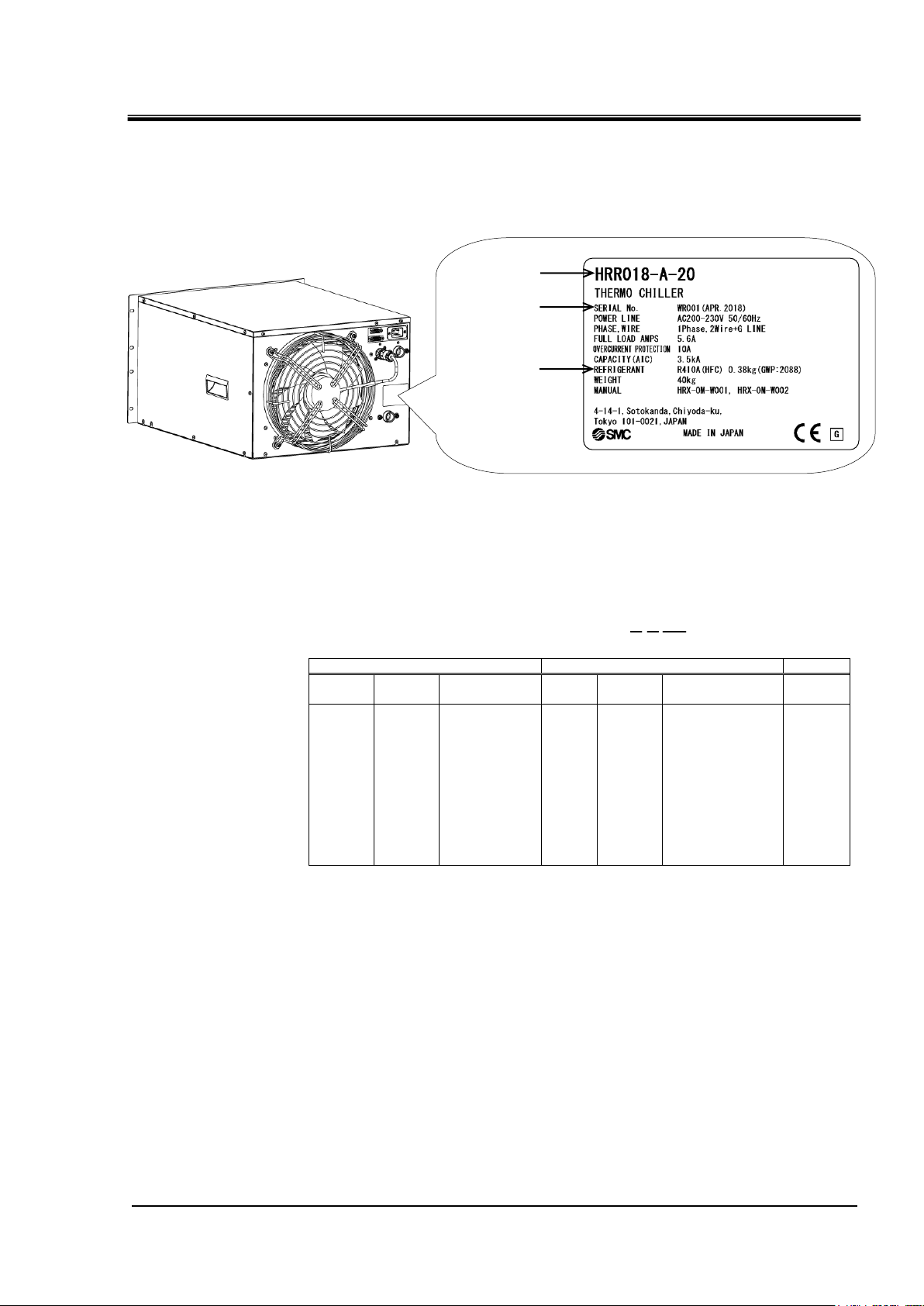
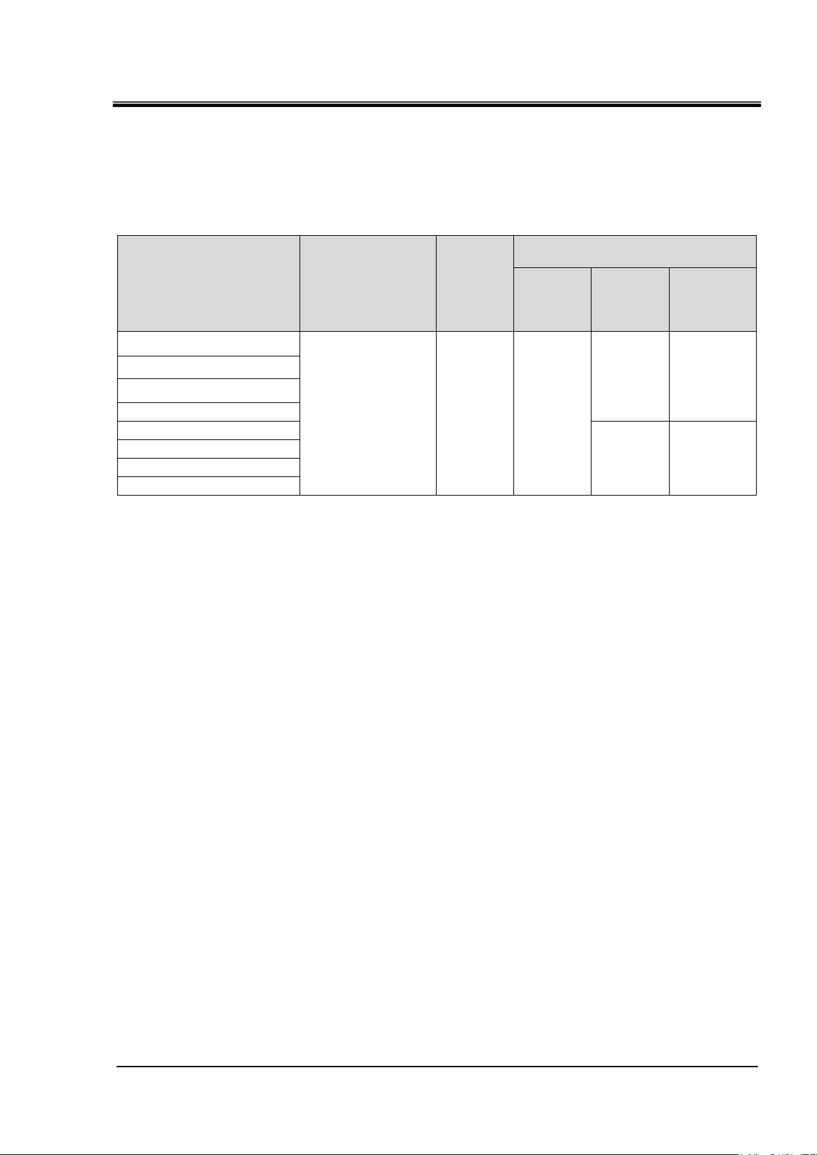
1.4 Product Label
W
R
001
Year
Symbol
Remarks
Month
Symbol
Remarks
Serial
no.
2018
W
Repeat
ed from
A to Zin
alphab
etical
order
4
R
Repeated
from
O to Z in
alphabetical
order, with O
for
January and
Z for
December
-
2019 X 5 S 2020 Y 6
T
↓ ↓ ↓
↓
Model number
Serial number
Type and
quantity of
refrigerant
Information about the product, such as Serial No. and Model No. can be
found on the product label. This information is needed when contacting an
SMC sales distributor.
HRX-OM-W002-A
Chapter 1 Safety Instructions
How to read the serial number W R 001 (April 2018)
Fig 1-1 Position of product label
HRR Series 1.4 Product Label
Page 10
HRX-OM-W002-A
1-4
Follow the instructions below when using the product. Failure to
follow the instructions may cause an accident and injury.
Always use safety shoes, gloves and head protection when
transporting, installing or uninstalling the product.
Always use safety shoes, gloves, mask, apron and eye protection
when handling the circulating fluid.
Always use safety shoes and gloves when operating the product.
Chapter 1 Safety Instructions
1.5 Safety Measures
1.5.1 Safety instructions for use
Read and understand this manual carefully before using the product.
Before starting maintenance of the product, be sure to lock out and tag out
the breaker of the user's power supply.
If operating the product during maintenance, be sure to inform all workers
nearby.
Use only the correct tools and procedure when installing or maintaining
the product.
Use personal protective equipment where specified (“1.5.2 Personal
protective equipment”).
Check all parts and screws are fitted correctly and securely after
maintenance.
Avoid working in a drunken or sick condition, which might cause an
accident.
Do not remove the panels except for the cases permitted in this manual.
Do not remove the panels during operation.
Do not handle this product by any means other than specified in this
Operation Manual; this can result in damage to the product or fire.
1.5.2 Personal protective equipment
This manual specifies personal protective equipment for each type of work.
Transport, Installing and Uninstalling
Handling of circulating fluid
Operation
1.5 Safety Measures
HRR Series
Page 11
HRX-OM-W002-A
1-5
OFF
Even when the power supply swich is turned off, some of the internal
circuits are still energized, unless the user’s power supply is shut off.
Be sure to shut off the breaker of the user’s power supply.
Chapter 1 Safety Instructions
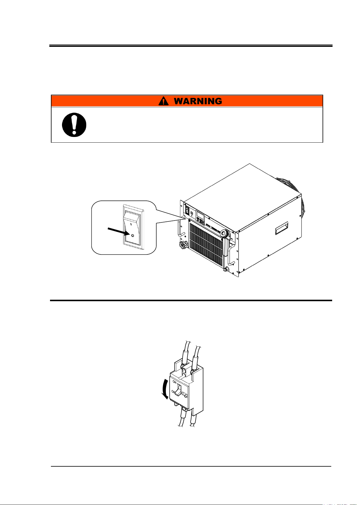
1.6 Emergency Measures
When emergency conditions such as natural disaster, fire and earthquake, or
injury occurs, turn off the power supply switch. After that, be sure to shut off
the breaker of the original power supply (customer's power supply
equipment).
1. Turn off the power supply switch on the front of the product to stop the operation of the
thermo-chiller.
.
Fig 1-2 Location of the switch for the power supply
2. Be sure to shut off the breaker of the facility power supply (the power supply of the
user’s machine).
Fig 1-3 Shut off of facility power supply
HRR Series 1.6 Emergency Measures
Page 12
HRX-OM-W002-A
1-6
Only maintenance personnel or qualified people are allowed to open
the cover panels of the product.
Do not mix the compressor oil with domestic waste for disposal. Also,
the disposal of the waste must only be conducted by specific
facilities that are permitted for that purpose.
Comply with the laws and regulations in each country for the disposal
of refrigerant and compressor oil.
The release of refrigerant in to the atmosphere is banned by law.
Recover it with specific equipment and dispose of it correctly.
Only people who have sufficient knowledge and experience about the
product and its accessories are allowed to recover the refrigerant and
compressor oil.
Chapter 1 Safety Instructions
1.7 Waste Disposal
1.7.1 Disposal of refrigerant and compressor oil
The product uses hydro fluorocarbon type refrigerant (HFC) and compressor
oil. Comply with the laws and regulations in each country for the disposal of
refrigerant and compressor oil. The type and quantity of refrigerant is
described on the “1.4 Product Label”.
If these fluids need to be recovered, read and understand the instructions
below carefully. If there is any unclear point, contact an SMC's sales
distributor.
1.7.2 Disposal of product
The disposal of the product must be handled by a specialized industrial waste
disposal agency in accordance with local laws and regulations.
1.7 Waste Disposal
HRR Series
Page 13

1-7
1.8 Material Safety Data Sheet (MSDS)
If the material safety data sheets of chemicals used in this product are
needed, contact an SMC's sales distributor.
Any chemicals used by the user must be accompanied by an MSDS.
HRX-OM-W002-A
Chapter 1 Safety Instructions
HRR Series 1.8 Material Safety Data Sheet (MSDS)
Page 14

HRX-OM-W002-A
1-8
Chapter 1 Safety Instructions
1.8 Material Safety Data Sheet (MSDS)
HRR Series
Page 15
HRX-OM-W002-A
2-1
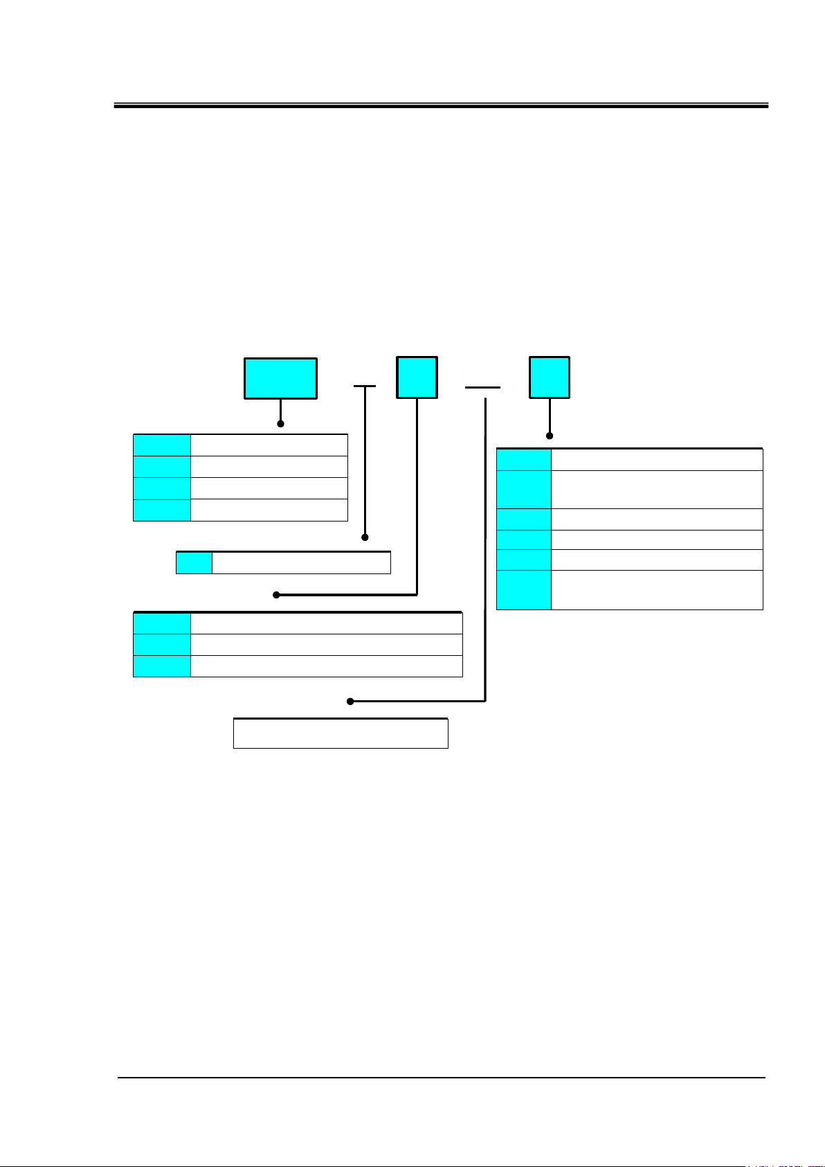
HRR
- - -
A
20
①Cooling capacity
012 1000W/1200W (50/60Hz)
030
024 2000W/2400W (50/60Hz)
2500W/3000W (50/60Hz)
018 1600W/1800W (50/60Hz)
②Cooling method
③Piping thread type
Null Rc
F G (Rc-G conversion fitting is included)
N NPT (Rc-NPTconversion fitting is included)
⑤Option
When option D is selected,M is selected it
becomes - DM. It is not possible to select
only D
UL-pending
④Power supply
1-phaseAC200 to 230V (50/60Hz)
A Air-cooled refrigerator type
Null None
DI water (Pure water) pipingM
Electric conductivity control
DI water (Pure water) piping
DM
High pressure pumpT
ULU
With feet and
no Rack Mounting bracket
Y
Chapter 2 Name and Function of Parts
Chapter 2 Name and Function of Parts
2.1 Model Number of Product
The product can be ordered with the model number configured as shown
below.
The product needs to be handled in different ways depending on the part
number. Refer to “1.4 Product Label" and check the part number of the
product.
2.1.1 Air-cooled refrigerator type
HRR Series 2.1 Model Number of Product
Fig 2-1 Part number of product (1/2)
Page 16

HRX-OM-W002-A
2-2
HRR
- - -
W
20
①Cooling capacity
012 1000W/1200W (50/60Hz)
030
024 2000W/2400W (50/60Hz)
2500W/3000W (50/60Hz)
018 1600W/1800W (50/60Hz)
②Cooling method
③Piping thread type
Null Rc
F G (Rc-G conversion fitting is included)
N NPT (Rc-NPTconversion fitting is included)
⑤Option
* When option D is selected,M is selected it
becomes - DM. It is not possible to select
only D
UL-pending
④Power supply
1-phaseAC200 to 230V (50/60Hz)
Water-Cooled refrigerated
type is the UL standard
prouduct. (UL-pending)
U
W Water-cooled refrigerator type
Null None
DI water (Pure water) pipingM
Electric conductivity control
DI water (Pure water) piping
DM
High pressure pumpT
With feet and
no Rack Mounting bracket
Y
Chapter 2 Name and Function of Parts
2.1.2 Water-cooled refrigerator type
Fig 2-2 Part number of product (2/2)
2.1 Model Number of Product HRR Series
Page 17

2-3
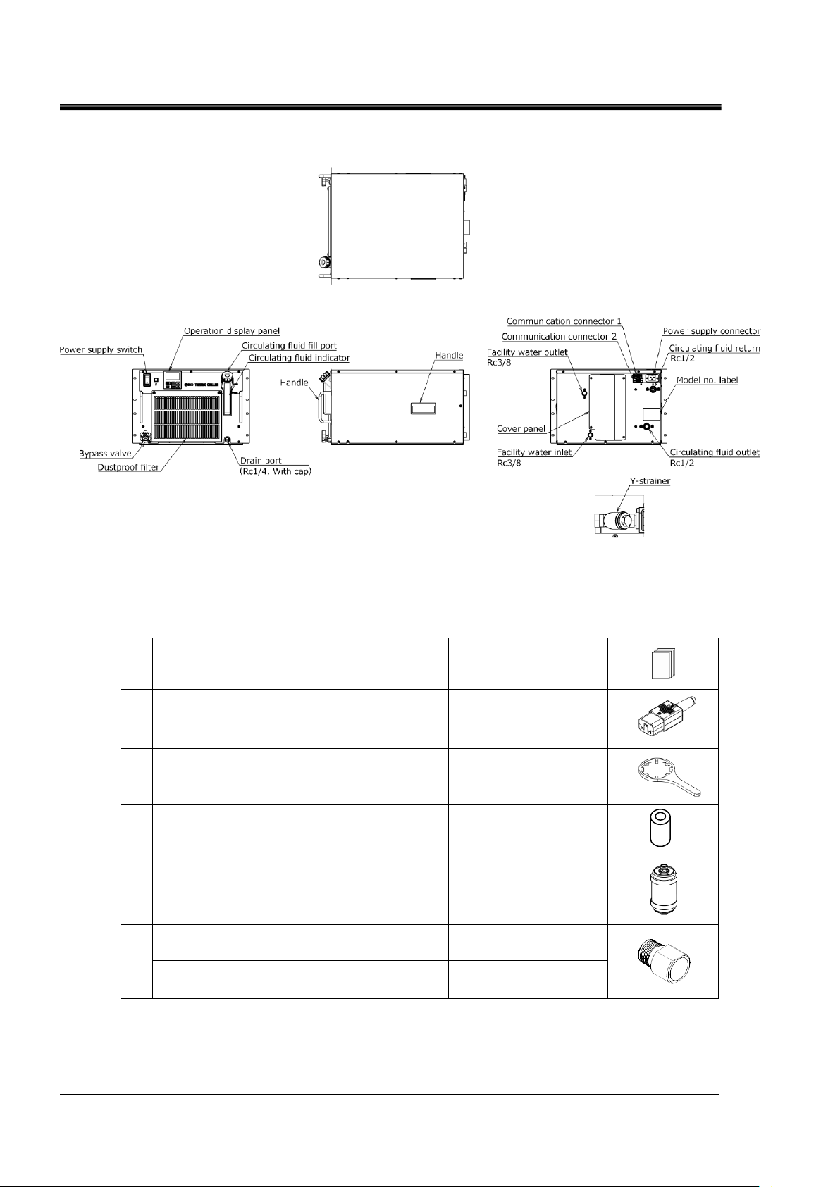
2.2 Name and Function of Parts
①
Operation manual
2 copies
(English 1 copy/
Japanese 1 copy)
②
Power supply connector
1 pc.
③
Maintenance handle for particle filter
1 pc.
④
Particle filter element
1 pc.
⑤
For option DM DI filter
1 pc.
⑥
For HRR-AF-20-
G thread adapter set
1 set
For HRR-AN-20-
NPT thread adapter set
1 set
2.2.1 HRR-A-20- (Air cooled type)
Fig 2-3 Names of the parts
Table 2-1 Accessory list
HRX-OM-W002-A
Chapter 2 Name and Function of Parts
HRR Series 2.2 Name and Function of Parts
Page 18
HRX-OM-W002-A
2-4
①
Operation manual
2 copies
(English 1 copy/
Japanese 1 copy)
②
Power supply connector
1 pc.
③
Maintenance handle for particle filter
1 pc.
④
Particle filter element
1 pc.
⑤
For option DM DI filter
1 pc.
⑥
For HRR-AF-20-
G thread adapter set
1 set
For HRR-AN-20-
NPT thread adapter set
1 set
Chapter 2 Name and Function of Parts
2.2.2 HRR-W-20-U(Water cooled type)
Fig 2-4 Names of the parts
Table 2-2 Accessory list
2.2 Name and Function of Parts HRR Series
Page 19

2-5
2.3 Function of Parts
Name
Name
Operation display panel
Runs and stops the product and performs settings such as the circulating
fluid temperature.
For details, refer to ’’2.4 Operation display panel’’.
Fluid level gauge
Indicates the circulating fluid level of the tank. For details, refer to ’’3.5 Fill
of circulating fluid’’.
Power supply switch
Shuts off the power supply to the internal eqipment of product.
Model label
Shows the part number of the product.
For details, refer to ‘’1.4 Product Label’’.
Circulating fluid outlet port
The circulating fluid flows out from the outlet port.
Circulating fluid return port
The circulating fluid returns to the return port.
Drain port
Port to drain the circulating fluid out of the tank.
Power supply connector
Connect the power cable to the Power supply connector
accessory, and then plug it in.
For details, refer to " 3.3.3 Preparation and wiring of power supply cable
".
Communication connector
CN1,CN2
Use for contact input / output, serial communication.
For details, refer to "3.3.3 Preparation and wiring of power supply
cable".
Facility water inlet
(For water-cooled type)
A facility water inlet to which the facility water is fed through piping.
The pressure of facility water should be in a range of 0.3 to 0.5MPa.
Facility water outlet
(For water-cooled type)
A facility water outlet from which the facility water returns to the user’s
machine through piping.
The function of parts is as follows
Table 2-3 Function of parts
HRX-OM-W002-A
Chapter 2 Name and Function of Parts
HRR Series 2.3 Function of Parts
Page 20
HRX-OM-W002-A
2-6
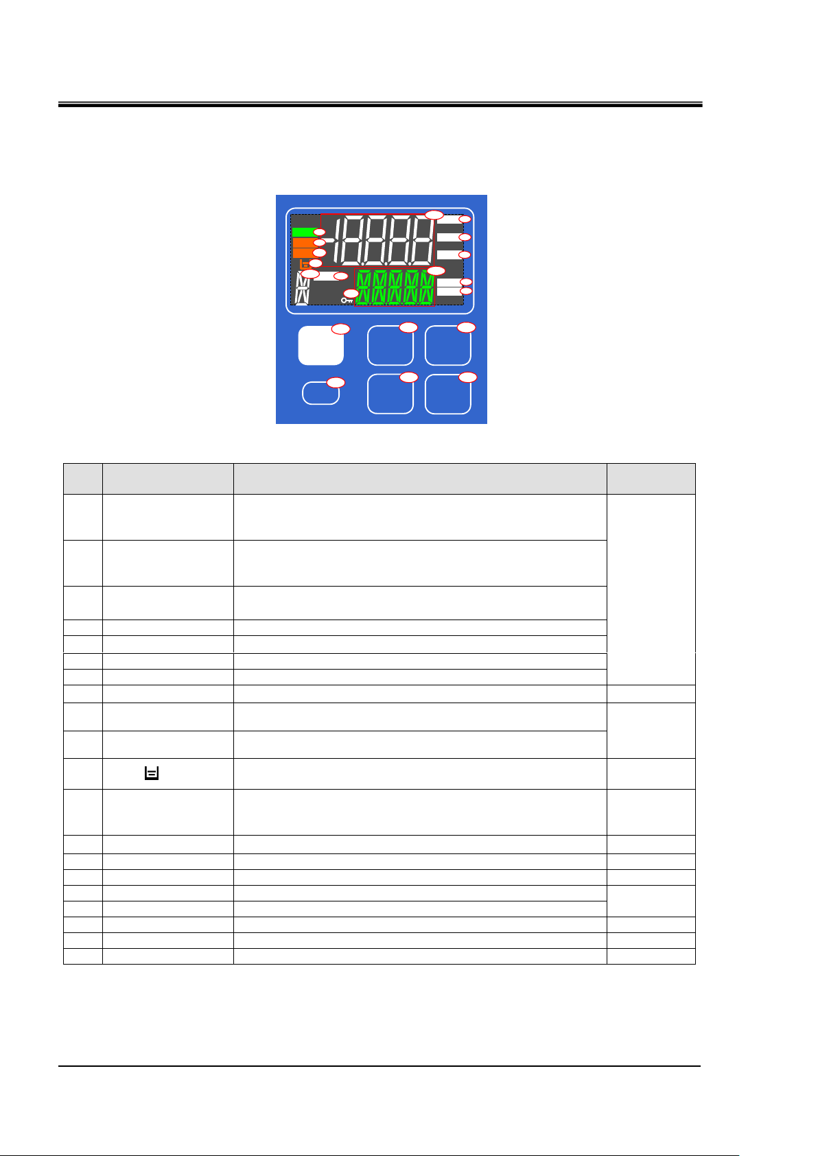
No
Name
Function
Reference
page
①
Digital display
(7 segment,
5 digits)
Displays the temperature,pressure and flow rate of the circulating fluid
and the set values of other menus.
5.2
②
Digital display
(11 segment,
5 digits)
Displays the discharge temperature of the circulating fluid and the set
values of other menus.
③
[oC] lamp
Lights up when temperature is displayed on the digital display.
④
[MPa] lamp
Lights up when pressure is displayed on the digital display part.
⑤
[LPM] lamp
Lights up when flow rate is displayed on the digital display part.
⑥
[H] lamp
Lights up when time is displayed on the digital display section.
⑦
[SEC] lamp
Lights up when seconds are displayed on the digital display section.
⑧
[RUN] lamp
Lights up when the product is started and in operation.
4
⑨
[ALM] lamp
Lights up when a fault occurs.
(This product will stop.)
7
⑩
[WRN] lamp
Lights up when a warning occurs.
(This product will continue operation.)
⑪
[ ] lamp
Lights up when 「AL.01 Tank level drop failure」 or
「AL.02 Tank level drop」alarm is generated.
-
⑫
Digital display
(11 segment,
1 digits)
「X」 is displayed when notice for maintenance is generated.
5.4.4
⑬
[RMT] amp
Lights up during remote operation by communication function.
5
⑭
[KEYLOCK] amp
Lights up when key lock setting is active.
5.5.3
⑮
[RUN/STOP] key
Press and hold for 1 second to start or stop.
4.2
⑯
[MENU] key
Switching of each menu and cancellation of setting values.
5
⑰
[ENT] key
Switch to setting mode and set values.
⑱
[▲] key
Move item upward or increase the set value.
-
⑲
[▼] key
Move item downward or decrease the set value.
- ⑳ [RESET] key
Reset the alarm.
7
▲
▼
ENT
MENU
RUN/
STOP
RESET
℃
MPa
LPM
SEC
ALM
WRN
RUN
RMT
H
15
20
16
17
18
19
12
14
2
1
6
7
5
4
3
13
8
9
10
11
Chapter 2 Name and Function of Parts
2.4 Operation display panel
The operation panel on the front of the product controls the basic operation of
the product
図 2-5 操作表示パネル
Table 2-4 Operation display panel
2.4 Operation display panel HRR Series
Page 21
Chapter 3 Transport and Setting Up
3-1
Only persons who have sufficient knowledge and experience about
the product and system are allowed to transport and set up the
product.
Especially pay attention to personal safety.
Never lay the product on its side.
The compressor oil will leak in to the refrigerant piping, which may
cause early failure of the compressor.
Drain the residual fluid from the piping as much as possible to prevent
any spillage.
Chapter 3 Transport and Setting Up
3.1 Transport
The product is heavy and has potential danger at transport. Also, to prevent
damage and breakage of the product, be sure to follow the instructions
shown below for transport.
HRX-OM-W002-A
HRR Series 3.1 Transport
Page 22
HRX-OM-W002-A
3-2
Do not set up the product in places possibly exposed to leakage of
flammable gas. Should any flammable gas stay around the product,
the product may cause a fire.
Do not use the product outdoors. If the product subjected to rain or
water splash it may cause electrical shock, fire or failure.
Keep the product upright on a rigid and flat floor which can resist the
weight of the product, and take measures to prevent the product from
tipping over. Improper installation may cause water leakage, tipping,
damage of the product or injure the operator.
Keep the ambient temperature of the product between 5 to 40oC.
Operation out of this ambient temperature range may cause a
malfunction of the product. Operating the product in an environment
temperature of 40 oC may reduce the heat discharging efficiency of
the heat exchanger and the safety device may function, which stops
the product operation.
The installer/end user is responsible for carrying
out an acoustic noise risk assessment on the equipment after
installation and taking appropriate measures as required.
Chapter 3 Transport and Setting Up
3.2 Installation
3.2.1 Environment
The product must not be operated, installed, stored or transported in the following
conditions. Potential malfunction or damage to the product may occur if these
instructions are disregarded.
● Location that is outside.
● Location that is exposed to steam, salt water or oil.
● Location that is exposed to dust or powder material.
● Location that is exposed to corrosive gas, organic solvent, chemical solution,
or flammable gas. (The product is not explosion-proof.)
● Location where the ambient temperature is out of the following range:
In transportation and In storage 0 to 50°C
(with no water or circulating fluid in piping)
During operation 5 to 40°C
● Location where the ambient humidity is out of the following range or where
condensation occurs:
● Location that is exposed to direct sunlight or heat radiation.
● Location that is near heat sources and poor in ventilation.
● Location that is subjected to abrupt changes in temperature.
● Location that is subjected to strong electromagnetic noise (intense electric
● Location that is subjected to static electricity, or conditions where static
● Location that is subjected to strong high frequencies raditation(microwaves).
● Location that is subjected to potential lightning srtike
● Location at altitude of 3000m or higher (except during product storage and
● Location where the product is affected by strong vibrations or impacts.
● Condition that applies external force or weight causing the product to be damaged.
Do not stack the product on top of each other.
● Location without adequate space for maintenance as required
● For the product installation or operation in accordance with UL standards, see below.
3.2 Installation
In transportation and storage 15 to 85%
In operation 30 to 70%
field, intense magnetic field, or surges).
electricity can discharge to the product.
transport). Refer to below for details.
HRR Series
Page 23

HRX-OM-W002-A
3-3
Altitude [m]
1. Max. ambient
temp. [°C]
2. Cooling capacity
correction coefficient
Less than 1000m
40
1.00
1000 m or more - Less than 1500 m
38
0.85
1500m or more - Less than 2000m
36
0.80
2000m or more - Less than 2500m
34
0.75
2500m or more - Less than 3000m
32
0.70
Chapter 3 Transport and Setting Up
Thermo-chiller installation in high altitude of 1000 meters or more
Because of lower air density, the heat radiation efficiencies of the devices in
the product will be lower in the location at altitude of 1000m or higher. For
this reason, the maximum ambient temperature for the thermo-chiller
operation and the cooling capacity will be reduced.
For product installation at a place of high altitude of 1000 meters or more,
select a thermo-chiller of the applicable capacity referring to the table below.
1. Max. ambient temp.: Use the product in lower ambient temperature than
the described value at each altitude.
2. Cooling capacity correction coefficient: Coefficient to calculate the cooling
capacity at each altitude
At an altitude of 1800 meters = Cooling capacity 8.4 x 0.8.
Installation/Operation in accordance with the UL standard (for the optional UL
compliant model)
For operation of the UL compliant model (available as an option,
HRR*-*-20-**U) in UL compliant conditions, the product cannot be used
in the environment shown below:
● Environment at an altitude of 2000 meters or more
● Environment at a pollution degree of 3 or more
HRR Series 3.2 Installation
Page 24
HRX-OM-W002-A
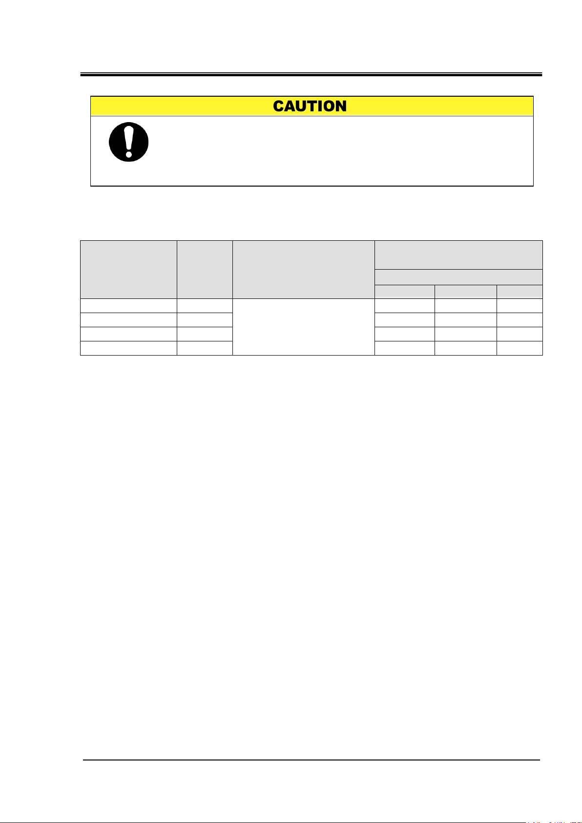
3-4
Model
Heat
radiation
(kW)
Required ventilation amount (m3/min)
Differential temp. of
3 °C between inside
and outside of
installation area
Differential temp. of
6 °C between inside
and outside of
installation area
HRR012-A-20-
Approx.2
40
20
HRR018-A-20-
Approx.4
70
40
HRR024-A-20-
Approx.5
90
50
HRR030-A-20-
Approx.6
100
60
Do not install in a location which can be subjected to any of the
conditions in “3.2.1 Environment”.
The air cooled product radiates heat from the air vent of the cooling fan.
If the product is operated with insufficient air ventilation the internal
temperature can exceed 40oC, which can cause and affect the
performance and life of the product. To prevent this ensure that
suitable ventilation is available (see below).
Chapter 3 Transport and Setting Up
3.2.2 Location
Installation of multiple products
Keep sufficient space between products so that the air vented from one
Installation at indoor site (for air cooled type)
product will not be taken in by other products.
1. For a facility having a large installation area (that can vent the air
naturally):
Make an air outlet on a wall at a high level and air inlet on a wall at a low
level, to allow for adequate airflow.
2. For a facility having a small installation area (that can not vent the air
naturally):
Make a forced air exhaust vent on a wall at a high level and an air inlet on a
wall at a low level.
Table 3-1 Amount of radiation and required ventilation
3.2 Installation
HRR Series
Page 25
Chapter 3 Transport and Setting Up
3-5
Model
Heat
Radiated
kW
Facility water temp.
range
o
C
Required facility water flow rate
l/min
Facility water temprature
25℃
32℃
40℃
HRR012-W-20-
Approx.2
5 to 40
(Rating 25)
8
12
20
HRR018-W-20-
Approx.4
12
15
23
HRR024-W-20-
Approx.5
14
17
25
HRR030-W-20-
Approx.6
15
18
26
The water cooled product radiates heat to the facility water.
It is necessary to supply the facility water. Please prepare the facility
water system that satisfies the heat radiation and the facility water
specifications below.
Required facility water system (for water cooled type)
Table 3-2 Facility water source to be prepared
HRX-OM-W002-A
HRR Series 3.2 Installation
Page 26
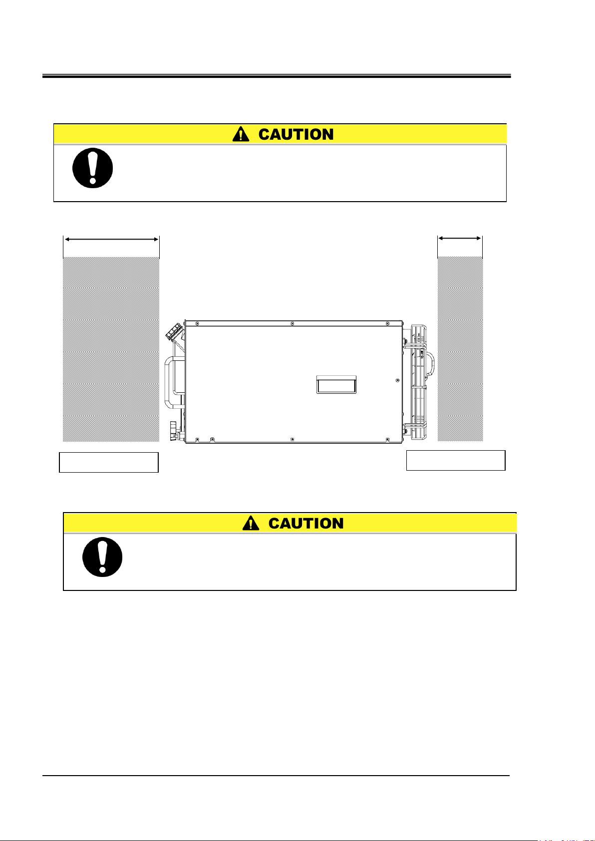
HRX-OM-W002-A
3-6
Have an enough space for the ventilation for the product. Otherwise it
may cause a lack of cooling capacity or/and stoppage of the product.
Ensure there is enough space for maintenance.
The temperature of the outlet for the ventilation of the thermo-chiller
and the panel surface may become approx. 50oC or higher. When
placing the thermo-chiller, ensure the thermo-chiller does not affect
surrounding environment.
Product front side
Product rear side
700mm or more
300mm or more
Chapter 3 Transport and Setting Up
3.2.3 Installation and Maintenance Space
It is recommended to keep the space around the product shown in Fig 3-1
Fig 3-1 Installation space(View from the side of the product)
3.2 Installation
HRR Series
Page 27
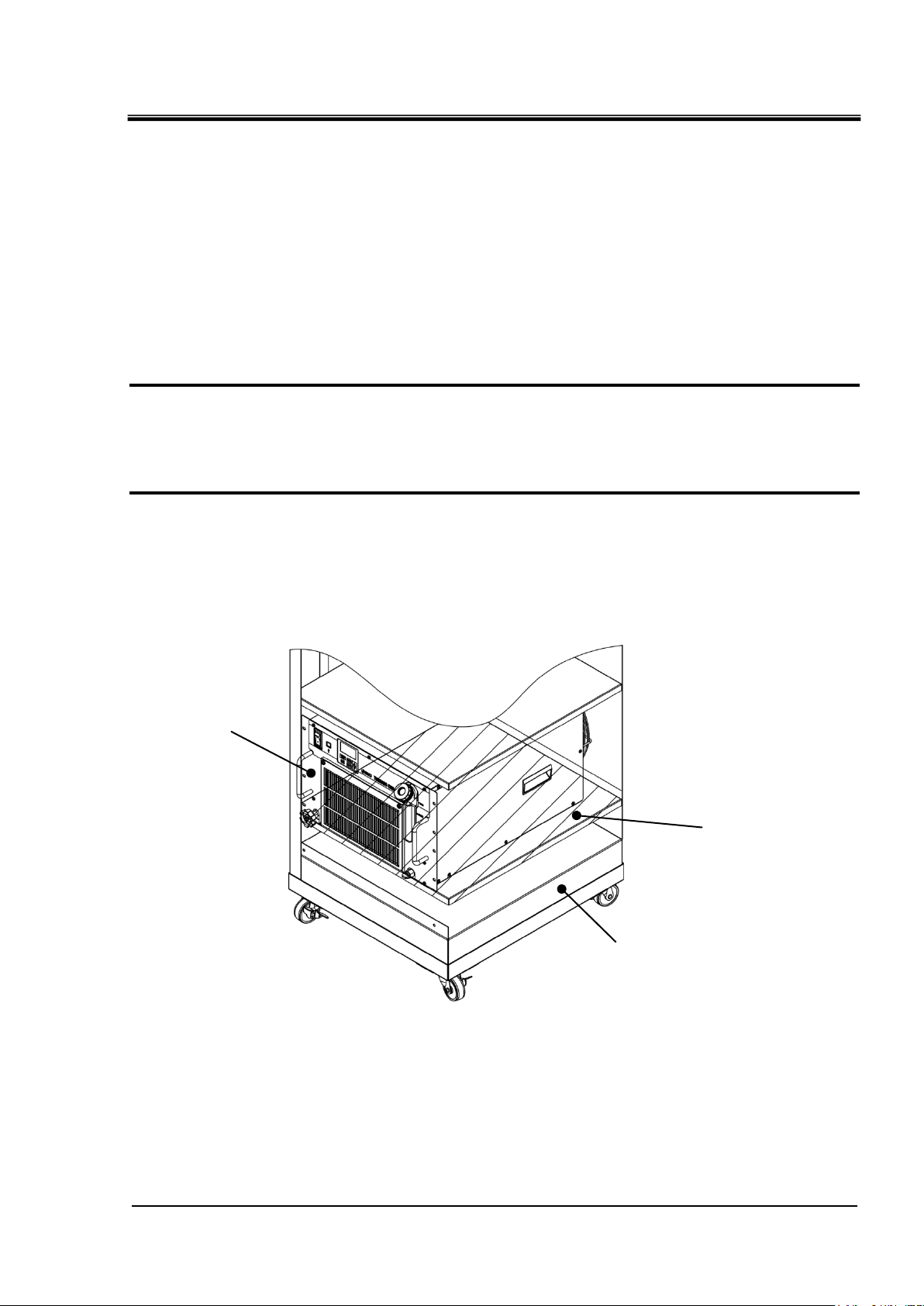
HRX-OM-W002-A
3-7
This product
Cabinet
Retaining panel etc
Chapter 3 Transport and Setting Up
3.3 Installation
3.3.1 Mounting
How to mount the product
1. When mounting the prouduct to a cabinet, use a design which shall hold the weight at
the bottom. Ensure safety with transportation test if the product is to be installed on a
transportation device such as atrailer. Mount the product using the fixing holes in the front of
the product. Use M5,M6 screws (bolts) or equivalent to the fix the product.
Do not drag this product after mounting, as the feet may be damaged. (option -Y)
2. In the case of air cooling type, this product sucks air from the front and discharges it to
the back. Please do not block the suction and the discharge air. Please do not install in
a sealed place. (Refer to 3.2.3 "Installation and maintenance space".)
Fig 3-1 Mounting
HRR Series 3.3 Installation
Page 28
HRX-OM-W002-A
3-8
Do not modify the internal electrical wiring of the product. Incorrect
wiring may cause electric shock or fire. Also, modifying the internal
wiring will void the product’s warranty.
NEVER connect the ground to water line, gas pipe or lightning
conductor.
The installation of electrical equipment and wiring work should be
performed only by personnel with sufficient knowledge and
experience.
Be sure to shut off the user’s power supply. Wiring with the product
energized is strictly prohibited.
The wiring must be conducted using cables complying with “Table
3-3” and firmly secured to the product to prevent the external force of
cables being applied to the terminals. Incomplete wiring, or improper
securing of wiring, may cause electrical shock or excessive heat and
fire.
Ensure a stable power supply with no voltage surges.
Ensure that an earth leakage breaker is used in the power supply of
the product. See “Table 3-3”.
Use a power supply suitable for the specifications of the product.
Use a power supply of over voltage category 3 (IEC60664-1)*.
Be sure to connect the ground connection.
Ensure that a lock out facility is availble on the power supply.
Each product must have its own separate earth leakage breaker.
Otherwise there can be a risk of electric shock or fire.
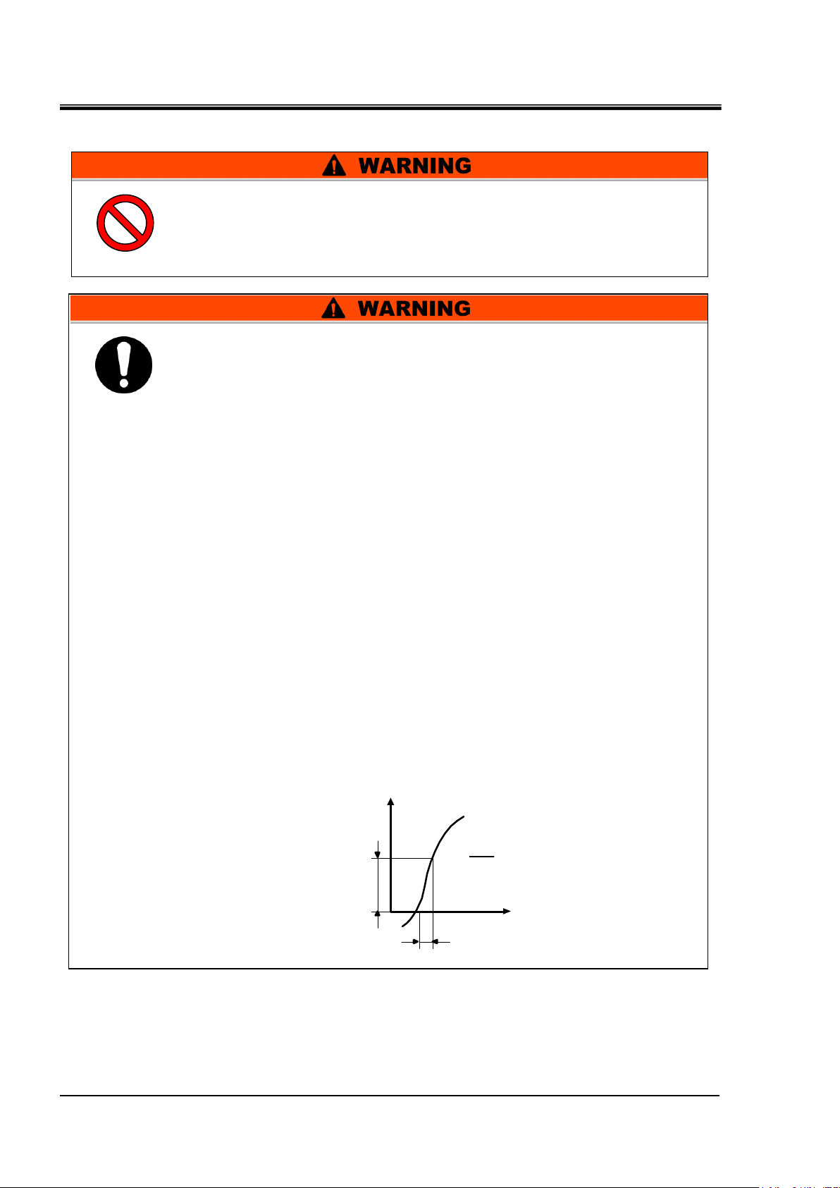
Ensure that no harmonics are superimposed at power supply.
(Do not use inverter, etc.)
Supply a steady power supply which is not affected by surges or
distortion. In particular, if the voltage rate of increase (dv/dt) at
zero crossing exceeds 40V/200μsec, it may cause malfunction.
V
dV
dt
dt
= Voltage ratio
on zero-cross point
dV
t
Voltage rise %
Time
Voltage
Chapter 3 Transport and Setting Up
3.3.2 Electrical wiring
*: For the users that purchased Option U for the product operation in the UL compliant conditions, please
refer to "Installation/Operation in accordance with the UL standard" in the next page.
3.3 Installation
HRR Series
Page 29
HRX-OM-W002-A
3-9
Model
(High pump head
[Optional])
Power supply
voltage
Cable
qty.
x size
Recommended earth
leakage breaker
Rated
voltage
[V]
Rated
current
(A)
Sensitivity
of leak
current
[mA]
HRR012-A/W-20-
1-phase
200-230V AC
(50/60Hz)
3 cores x
14AWG
(3 cores x
2.0mm2)
(including
ground)
200,
230
10
30
HRR018-A/W-20-
HRR024-A/W-20-
HRR030-A/W-20-
HRR012-A/W-20-T
15
30
HRR018-A/W-20-T
HRR024-A/W-20-T
HRR030-A/W-20-T
Chapter 3 Transport and Setting Up
Power supply specifications, power supply cable and earth leakage breaker
Prepare the power supply shown in the following table. For the connection between the product and
power supply, use the power supply cable and earth leakage breaker shown below. An earth leakage
breaker must be mounted to a position where the breaker is easily accessible and close to the
thermo-chiller.
Table 3-3 Power supply cable and earth leakage breaker (Recommended)
Installation/operation in accordance with the UL standard (for the optional UL
compliant model)
For operation of the UL compliant model (available as an option, HRR--20-U) in the UL
compliant conditions, the conditions shown below must be satisfied:
● Use power supply of overvoltage category 2 (transient overvoltage 2500 V or less)
*1 When using a power supply in the overvoltage category 3, take measures such as
mounting an isolation transformer between the product and the power supply or keep the
transient overvoltage of the power supply to 2500 V or less by using a varistor, etc.
*1
HRR Series 3.3 Installation
Page 30
HRX-OM-W002-A
3-10
The electrical facilities should be installed and wired in accordance
with local laws and regulations of each country and by a person who
has knowledge and experience.
Check the power supply. Operation with voltages, capacities and
frequencies other than the specified values can cause fire and
electric shock.
Wire with an applicable cable size and terminal. Forcibly mounting
with an unsuitably size cable may result in heat generation or fire.
Be sure to lock out and tag out the breaker of the facility power supply
(customer power supply facility) before wiring.
Be sure to connect the power supply cable from the product side first,
and then connect the breaker of the facility power supply (the user’s
machine power supply).
Please wear protective gloves.
Use a separate outlet or earth leakage breaker.
Be sure to perform grounding (earth).
Failure to do so may cause malfunction or electric shock.
Chapter 3 Transport and Setting Up
3.3.3 Preparation and wiring of power supply cable
3.3 Installation
HRR Series
Page 31

HRX-OM-W002-A
3-11
Cable
Qty. x size
3cores×14AWG
(3cores×2.0mm2)
*including ground
To customer facilities
crimped terminal etc.
Power supply connector
N
E(Earth)
L
Power supply connector
Power supply connector hole
Earth leakage breaker
Chapter 3 Transport and Setting Up
Preparation
1. Prepare the cable and individual socket or earth leakagebreaker shown in the table
below.
2. Strip the sheath from both ends of the cable.
3. Disassemble the power supply connector (supplied as an accessory) and mount one
end of the cable to the L, N and E terminals and reassemble the power supply
connector.
4. Connect the other end of the cable to crimped terminals that are connectable to the
power supply facility.
Fig 3-3 Cable connection
5. Insert the power supply connector to the power supply connector socket.
6. Connect the crimped terminals to the secondary side of the earth leakage breaker and
HRR Series 3.3 Installation
grounding on the power supply facility
Fig 3-4 Power supply connector connection
Page 32

HRX-OM-W002-A
3-12
Connector specification (this product side)
Dsub 15 pin female (socket) type
Item
Specification
Contact
input
signal1,2
Insulation system
Photo coupler
・ Run/Stop signal
・ External switch signal
Rated input
voltage
DC24V
Used input voltage
DC 21.6V to 26.4V
Rated input
current
5mA TYP
Input signal
4.7kΩ
Contact
output
signal
1,2,3
Rated load voltage
AC48V or less /DC30V or less
・ Signal of operating status
・ Signal for the alarm status
・ Signal for completion of
preparation
(TEMP READY) etc 2
Maximum load
current
AC/DC 500mA(Resistance
load)
Minimum load
current
DC5V 10mA
DC24V output voltage
DC24V±10% 500mA MAX 1
(It can not be used for inductive load.)
Be sure to lock out and tag out the breaker of the facility power supply
(the user’s machine power supply) before wiring.
Use a connector that is specified.
The capacity of the output contact of the product is limited. If the capacity is not
large enough, install a relay, etc. (to allow for larger capacity). Also, ensure that the
input current of the relay is small enough in relation to the contact capacity of the
product.
Chapter 3 Transport and Setting Up
3.3.4 Contact input/output communication wiring
The product has a contact input/output communication function as shown
below. Connect cables referring to the applicable chapter for each function.
(For details of the functions, refer to Operation Manual Communication
Function.)
Run/Stop input・Remote signal input (Refer to “3.3.5 Wiring of
run/stop signal input and remote signal input”)
Output of contact output signal (Refer to “3.3.6 Wiring of contact
output signal Wiring of contact output signal”))
Use the signal cable described below for wiring of each function.
Contact Input/Output communication connector
The following connectors are used for this product as a contact input / output
signal connector. Please prepare suitable mating connector cable.
Table 3-4 Contact input/output communication connector
Table 3-5 Contact input/output communication specification
*1 : When using the power supply of this product, make sure that the total load current is 500 mA or
less.
*2 :Refer to "3.3.6 Wiring of contact output signal"。
3.3 Installation
HRR Series
Page 33
3-13
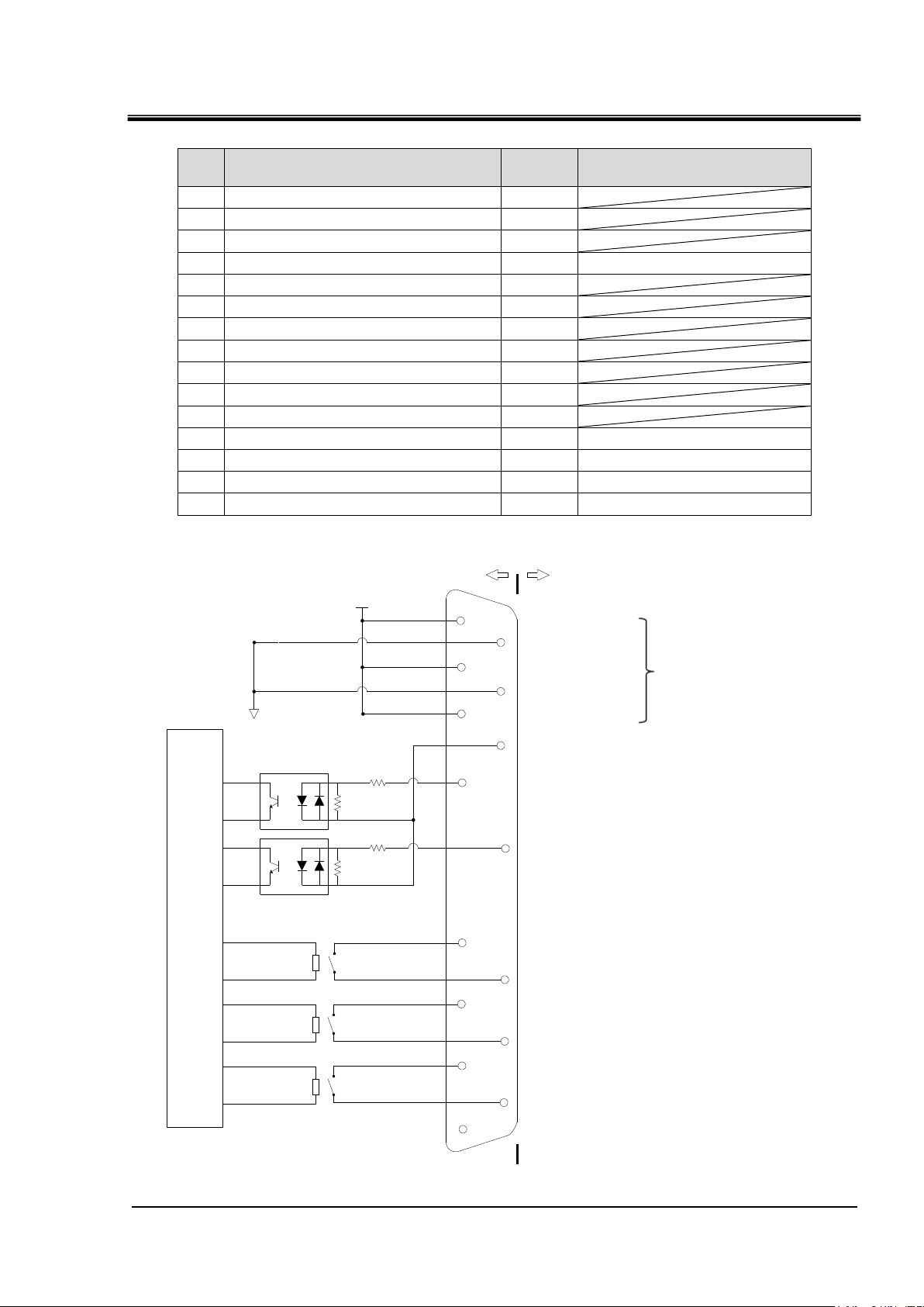
Table 3-6 Contact input/output pin number
PIN
no
Application
Division
Initial value
(Default setting)
1
DC 24V output
Output
2
DC 24V output
Output
3
DC 24V output
Output
4
Contact input signal 1
Input
None
5
COM of contact output signal 1
Output
6
COM of contact output signal 2
Output
7
COM of contact output signal 3
Output
8 None
- 9
24 COM output
Output
10
24 COM output
Output
11
COM of contact input signal
Output
12
Contact input signal 2
Input
None
13
Contact output signal 1
Output
Run status signal (N.O type)
14
Contact output signal 2
Output
Remote signal (N.O type)
15
Contact output signal 3
Output
Alarm signal (N.C type)
Internal
circuit
1kΩ
4.7kΩ
1kΩ
4.7kΩ
11
4
12
6
14
7
15
8
5
13
3
10
2
9
1
DC24V
24COM
This product Your system
DC24V output
24COM output
DC24V output
24COM output
DC24V output
MAX 0.5A
COM of contact input signal
Contact input signal 1:OFF
(Default unsetting)
Contact input signal 2:OFF
(Default unsetting)
COM of contact output signal 1
Contact output signal 1:Run status
(Default unsetting)
COM of contact output signal 2
Contact output signal 2:Remote
(Default unsetting)
COM of contact output signal 3
Contact output signal :Alarm
(Default unsetting)
None
HRX-OM-W002-A
Chapter 3 Transport and Setting Up
HRR Series 3.3 Installation
Fig 3-5 Contact input/output
Page 34

HRX-OM-W002-A
3-14
8
1
15
9
Dsub 15 pin female (socket) type
←Run/stop signal
Contact input/output signal connector
〃
1
4
9
Pin No.
〃
〃
11
Chapter 3 Transport and Setting Up
3.3.5 Wiring of run/stop signal input and remote signal input
Run/Stop signal input and remote signal input enable the product to run/stop
remotely by applying a contact signal input. This chapter illustrates examples
of wiring.
To enable the run/stop signal input or remote signal input, after wiring, set the
item "Contact input signal 1 function selection" in "Communication setting
menu" from "OFF (initial setting value)" → to "RN .ST ".
【Tips】
This product has two input signals. These can be customized depending on
the customer’s application.
1. Prepare a suitable connector cable.
2. Wire the contact input / output signal connector as shown below and connect it to this
product.(This wiring is an example, please refer to the instruction manual
"Communication function" for details.)
Fig 3-6 Wiring of run/stop signal input (Example)
3.3 Installation
HRR Series
Page 35

3-15
3.3.6 Wiring of contact output signal
Contact output
Content of the signal
(Default setting)
Operation
Contact output signal 1
Operation status signal
output
N.O.
During operation:
Contact closed
During operation
stop:
Contact open
With power supply
cutoff:
Contact open
Contact output signal 2
Remote status signal
output
N.O.
During remote
operation:
Contact closed
During
non-remote
operation:
Contact open
With power supply
cutoff:
Contact open
Contact output signal 3
Alarm status signal
output
N.C
While alarm being
generated:
Contact open
While alarm not
being generated:
Contact closed
With power supply
shut off:
Contact open
Be sure to turn OFF the breaker of the facility power supply (the user's
machine power supply) before wiring.
Contact output signals are the signals that output the status of this
product.
Contact specification of each signal output is shown below.
Table 3-7 Signal output contact spec. at the time of shipment
HRX-OM-W002-A
Chapter 3 Transport and Setting Up
[Tips]
This product has three output signals which can be customized depending on
the user’s application
Signals shown below can be output. Refer to Operation Manual
“Communication Function” for more details.
・Run status signal is output
・Remote status signal is output
・External temperature control status signal is output
・Signal for completion of preparation (TEMP READY) is output
・Out of temperature range status signal is output
・Signal for operation stop alarm is output
・Signal for continuing operation alarm is output
・maintenance status signal is output
・Alarm status signal is output
・Pass through signal of contact input signal is output
HRR Series 3.3 Installation
Page 36

HRX-OM-W002-A
3-16
Connector specification (this product side)
Dsub 9 pin female (socket) type
RS-485 communication connector
5
1 9 6
Dsub 9 pin female (socket) type
Chapter 3 Transport and Setting Up
・Selected alarm status signal output
・Signal for selection maintenance is output
3.3.7 RS-485 communication wiring
Serial communication RS-485, operation Start/Stop, setting and reading of
circulating fluid temperature, and reading of alarm condition can be
performed by remote control.
Refer to Operation Manual “Communication Function” for more details.
RS-485 communication connector
The following connector is used for this product as a connector for RS - 485
communication.
Please prepare suitable mating connector.
Table 3-8 RS-485 communication connector
Fig 3-6 RS-485 communication connector
3.3 Installation
HRR Series
Page 37

HRX-OM-W002-A
3-17
Be sure to turn OFF the breaker of the facility power supply (the
user's machine power supply) before wiring.
1
SD+
5
SG
9
SD-
SD+
SD- SG
Terminal
resistance
Master This product
(first slave)
1
SD+
5
SG
9
SD-
This product
(second slave)
1
SD+
5
SG
9
SD-
This product
(31st slaves)
Terminal
resistance120Ω
Chapter 3 Transport and Setting Up
Wiring of interface communication cable
Connecting to PC
RS-485 cannot be directly connected to a normal PC. Use an RS-232C/RS485 converter which is
available on the market.
Be sure to follow the wiring procedure shown below for connecting multiple thermo-chillers.
Configuration of connection
One thermo-chiller for one host computer, or multiple thermo-chillers for one host
computer.(31 thermo-chillers can be connected at maximum.)
Fig 3-7 Connection of RS-485
[Tips]
Both ends of the communication connection (the end nodes) need to be
connected to the host computer.
With or without the terminating resistor of this product can be set by the
operation display panel. Refer to “5.5.5 Communication setting menu”
HRR Series 3.3 Installation
Page 38

HRX-OM-W002-A
3-18
Connector specification (this product side)
Dsub 9 pin female (socket) type
2
3
5
RD
SD
SG
2
3
5
RD
SD
SG
Master This product
Be sure to turn OFF the breaker of the facility power supply (the
user's machine power supply) before wiring.
Chapter 3 Transport and Setting Up
3.3.8 RS-232C communication wiring
Serial communication RS-232C, operation start/stop, setting and reading of
circulating fluid temperature, and reading of alarm condition can be
performed by remote control.
Refer to Operation Manual “Communication Function” for more details.
RS-232C communication connector
The following connector is used for this product as RS-232C communication
connector.Please prepare suitable mating connector.
Table 3-9 RS-232C communication connector
Wiring of communication cable
Be sure to wire as shown in the figure below.
Configuration
One thermo-chiller for one master.
3.3 Installation
Fig. 3-8 Connection of RS-232C
HRR Series
Page 39

3-19
3.4 Piping
Description
Port
size
Recommended
tightening torque
Recommended piping
specifications
Circulating fluid outlet port
Rc1/2
28 to 30N・m
0.4M or more*2
Circulating fluid return port
Rc1/2
28 to 30N・m
0.4M or more*2
Facility water inlet port *3
Rc3/8
22 to 24N・m
1.0MPa or more
(Supply puressure: 0.3 to 0.5MPa)
Facility water outlet port *3
Rc3/8
22 to 24N・m
Connect piping firmly. Incorrect piping might cause leakage of
supplied or drained fluid and wet surrounding area and facility.
Use caution not to allow dust and foreign matter to enter the water
circuit, etc. during connection of piping.
Securely connect the piping at the piping port with specific wrench
when tightening.
Incorrect piping can burst in service.
Use non-corrosive material for fluid contact parts of circulating fluid
and/or facility water. Using the materials that tend to rust or corrode
may cause clogging or/and leakages of the circulating fluid and
facility water circuits. In case of using these kinds of materials,
consider and carry out some prevention against the rusting or
corrosion by the customer side.
Do not generate a rapid change of pressure by water hammer, etc.
Internal parts of the product and/or the piping may be damaged.
It is recommended to use heat insulation to reduce the heat radiation
and absorption to/from customer's piping.
Check the model number of this product in "1.4 Product Label” of this
manual before connecting piping.
Model number: HRR0-N-20
The transition connector from Rc to NPT is enclosed as an accessory.
For NPT piping, be sure to use this connector.
Model number: HRR-F-20
The transition connector from Rc to G is enclosed as an accessory.
For G piping, be sure to use this connector.
Piping port size
HRX-OM-W002-A
Chapter 3 Transport and Setting Up
Table 3-10 Piping port size
1 For NPT and G thread, use a conversion connector available as an accessory separately.
2 In the case of option T [High pressure pump], 1.0 MPa or more
3 For water-cooled type.
HRR Series 3.4 Piping
Page 40

HRX-OM-W002-A
3-20
[Tightening torque:28 to 30N・m]
Circulating fluid
return port Rc1/2
Circulating fluid
outlet Rc1/2
From the outlet
To the inlet
Chapter 3 Transport and Setting Up
[Tips]
<For HRR-AN-20-、HRR-WN-20->
A set of thread adapters that converts the connections from Rc to NPT is
enclosed as an accessory. For NPT thread, be sure to use this adapter.
<For HRR-AF-20-、HRR-WF-20->
A set of thread adapters that converts the connections from Rc to G is
enclosed as an accessory. For G thread, be sure to use this adapter.
How to connect piping
1. Ensure that the power source and the power supply of the
Product is turned off (or the power plug is disconnected).
2. This product generates an alarm and stops running when the circulating fluid flow rate
becomes 3 LPM or less. Please make piping that flows more than 3 LPM.
In addition, this product generates an alarm and stops when the circulating fluid
discharge pressure becomes 0.5 MPa or more.
[Tips]
When delivered, the bypass valve of this product is in the "open" state.
Adjust the bypass valve according to usage situation.
3. Connect the circulating fluid return port with the user’s
machine outlet.
4. Connect the circulating fluid discharge port with the user’s
machine inlet.
3.4 Piping
Fig. 3-9 How to connect piping (For air-cooled type)
HRR Series
Page 41

HRX-OM-W002-A
3-21
№
Description
Size
1
Valve
Rc1/2
2
Pressure gauge
0 to 1.0MPa
3
Pipe,hose,etc.
inside diameter Φ15 or more
Thermo-chiller
Circulating fluid
return port
Circulating fluid
outlet
Facillity water outret
(Water-cooled refrigeration)
Facillity water inlet
(Water-cooled refrigeration)
User's
equipment
1
1
1
1
1
1
2
Facility
water
branch
1
Tightening
torque
Rc1/2:28 to 30N・m
Rc3/8:22 to 24N・m
To the inlet
From the outlet
From the user’s
water source outlet
To the user’s
water source inlet
Circulating fluid outlet
Rc1/2
Circulating fluid Return port
Rc1/2
Facility water inlet
Rc3/8
Facility water outlet
Rc3/8
Chapter 3 Transport and Setting Up
5. In case of water-cooled type, please also connect the piping of the facility water inlet
and outlet of the customer’s water source equipment.
Recommended piping circuit
Fig. 3-10 Recommended piping circuit
HRR Series 3.4 Piping
Page 42

HRX-OM-W002-A
3-22
Item
No
Remarks
Ethylene glycol aqueous solution 60%
HRZ-BR001
Please dilute to 15% with tap
water and use it.
Densitometer
HRZ-BR002
-
Circulating fluid
Liquid supply
Lid
Drain port
Liquid level
Chapter 3 Transport and Setting Up
3.5 Fill of circulating fluid
1. Ensure that the power source and the power supply of the product is turned off.
2. Check the drain port is plugged to prevent the supplied circulating fluid from draining out.
3. Open the circulating fluid inlet cap by turning it counterclockwise, and fill the circulating fluid
within the range from LOW to HIGH shown on the level gauge.
Use tap water which satisfies the water quality standard shown inTable 8-, or a 15% aqueous
solution of ethylene glycol.
4. After filling to the specified level, turn the lid clockwise to close.
Fig. 3-11 Fill of circulating fluid
15% aqueous solution of ethylene glycol
When a 15% aqueous solution of ethylene glycol is used, prepare the ethylene glycol aqueous solution
separately.
To control the concentration of the ethylene glycol aqueous solution, a concentration meter is available
separately from SMC.
3.5 Fill of circulating fluid
HRR Series
Page 43

Chapter 4 Starting the Product
4-1
Only people who have sufficient knowledge and experience about the
product and its accessories are allowed to start and stop the product.
Facility water quality must satisfy the quality standard shown in ”
8.1 Quality Control of Circulating Fluid and Facility Water” and the
conditions shown in “9.1 Specifications”.
Chapter 4 Starting the Product
4.1 Before Starting
Check the following points before starting the product.
Installation state
Check that the product is installed horizontally.
Check that there are no heavy objects on the product, and the external
piping is not applying excessive force to the product.
Connection of cables
Check that the power, ground and signal cables (to be supplied by user)
are correctly connected.
Circulating fluid piping
Check that the circulating fluid piping is correctly connected to the inlet
and outlet.
Piping to automatic water fill port
Confirm that the piping to the automatic water fill port is correctly
connected.
Piping to overflow port
Piping must be connected to the overflow port regardless of using or not
using the automatic water fill function.
Confirm that the piping to the overflow port is correctly connected.
Fluid level gauge
Confirm that the fluid level is between ‘HIGH’ and ‘LOW’ levels of the
fluid level gauge.
Facility water piping (for water cooled type)
Check that the piping is correctly connected to the facility water inlet and
outlet ports.
Confirm that the facility water source is in operation.
Confirm that the facility water circuit is not closed with a valve, etc.
HRX-OM-W002-A
[Tips]
A water control valve is mounted inside the water cooled type thermo-chiller.
For the water cooled type, facility water may not run without operating the
product.
HRR Series 4.1 Before Starting
Page 44

HRX-OM-W002-A
4-2
ON
▲
▼
ENT
MENU
RUN/
STOP
RESET
℃
MPa
LPM
SEC
ALM
WRN
RUN
RMT
H
Press and hold for
approximately 1second.
Lighting up
▲
MENU
RUN/
STOP
℃
MPa
PSI
LPM
GPM
MΩ
SEC
ALM
WRN
RUN
RMT
AT
°F
EXT
H
%
ECO
RUN
Chapter 4 Starting the Product
4.2 Starting and Stopping
4.2.1 Operation
1. Please supply power to this product
Turn on the power switch. The operation display panel lights up. At this point, this
product is in the "Stopped" state (Please note that operation is started after the
power is turned on when the operation signal is sent in the remote setting state.)
Fig. 4-1 Power switch location
2. Set the circulating fluid temperature. When you press the "ENT" key, the set temperature (lower
part of numerical value display: green) flashes. Press the [▲] [▼] key to set the target
temperature, then press the "ENT" key to set.
(Flashing ends when set.) Please refer to various setting / display.
3. Press and hold [RUN / STOP] key for 1 second. The [RUN] lamp lights up and operation starts.
When you operate for the first time after piping, the circulating fluid in the tank decreases until
the circulating fluid is filled in the piping. (An alarm occurs when the liquid level falls below
"LOW".) When the circulating fluid in the tank decreases, repeat "Circulating liquid supply"
procedure so that the liquid level is within the range from LOW to HIGH. 30 seconds after start
of operation, if the circulating fluid flow rate is less than 3 L / min, an alarm occurs and the
product stops. Ensure that the circulating fluid flow rate will be 3 L / min or more.
When using option T (high head pump specification), if the circulating fluid discharge pressure
becomes 0.5 MPa or more, an alarm occurs and this product stops. Refer to "4.3 Adjustment of
bypass valve" and make it to 0.5 MPa or less.
4.2 Starting and Stopping
Fig 4-2 Operation
HRR Series
Page 45

HRX-OM-W002-A
4-3
▲
▼
ENT
MENU
RUN/
STOP
RESET
℃
MPa
LPM
SEC
ALM
WRN
RUN
RMT
H
After resetting the alarm, press and
hold for approximately 1 second.
Flash
▲
MENU
RUN/
STOP
℃
MPa
PSI
LPM
GPM
MΩ
SEC
ALM
WRN
RUN
RMT
AT
°F
EXT
H
%
ECO
RUN
Chapter 4 Starting the Product
4.2.2 Operation restart when alarm is generated
This product has two types of operation depending on the alarm being generated.
The restart is different depending on the operation mode.
[ 1 ] When the following alarm occurs, this product stops.
・AL01:Low level in tank
・AL17:flow rate failure
・AL18:High circulating fluid discharge temp
・AL19:High circulating fluid return temp.
・AL21:High circulating fluid discharge pressure
・AL24:Memory abnormal
・AL27:forced a stop
・AL30: refrigerant circuit abnormal
・AL31:sensor abnormal
・AL32: controller abnormal
After resetting the alarm (Refer to 「10. How to Reset Alarms 」) when resuming operations press
and hold the. [RUN/STOP] key for approximately 1 second. (Refer to “Chapter 7 Alarm Notification
and Troubleshooting“)
[ 2 ] When alarms except those shown above are generated the compressor stops, and the
circulating fluid pump continues running for a fixed time (*).
At this time, the "RUN" lamp flashes.
In case of resetting the alarm (Refer to 7.3 "What to do when an alarm
occurs") while the pump is operating, pressing the "RUN / STOP" key once (1 second)
causes the compressor to operate and the operation of the product will resume.
(This operation only occurs when this function is set. For details, refer to 5.3.6 Alarm Setting
Menu. )
To stop the product when only the pump is running, press and hold the [RUN/STOP] key for
approximately 5 seconds.
(When this operation is performed, an alarm "AL27: forced a stop " occurs.)
HRR Series 4.2 Starting and Stopping
Fig 4-3 Restart operation when an alarm occurs
Page 46

HRX-OM-W002-A
4-4
▲
▼
ENT
MENU
RUN/
STOP
RESET
℃
MPa
LPM
SEC
ALM
WRN
RUN
RMT
H
Press and hold for
approximately 5 second.
Flash
▲
MENU
RUN/
STOP
℃
MPa
PSI
LPM
GPM
MΩ
SEC
ALM
WRN
RUN
RMT
AT
°F
EXT
H
%
ECO
RUN
Chapter 4 Starting the Product
*The time to run the pump can be set within the range of "0 to 9999 seconds". The factory setting is "0
seconds". Therefore, when an alarm occurs, the operation is as in operation mode [1] .the operation
of the pump stops and the product stops. However, if the user sets the pump operation time greater
than 0s, the pump only runs until the circulating fluid discharge temperature reaches a certain value.
The factory setting is set to 40
o
10
C to 45 oC. See "5.3.6 Alarm Setting Menu" for details).
4.2 Starting and Stopping
Fig 4-4 Restart operation when an alarm occurs
o
C (The cut off temperature can be set by the user within the range of
HRR Series
Page 47

4-5
Except in case of an emergency, do not turn OFF the breaker before
the thermo-chiller stops operation completely.
4.2.3 Stopping the product
▲
▼
ENT
MENU
RUN/
STOP
RESET
℃
MPa
LPM
SEC
ALM
WRN
RUN
RMT
H
Flash→Lights off
RUN
Press and hold for
approximately 1
second.
▲
MENU
RUN/
STOP
℃
MPa
PSI
LPM
GPM
MΩ
SEC
ALM
WRN
RUN
RMT
AT
°F
EXT
H
%
ECO
Press and hold the [RUN / STOP] key for 1 second.
[RUN] lamp goes out and operation stops.
*It takes about 10 seconds of operation to prepare to stop before it stops.
During the stopping preparation the [RUN] lamp flashes.
Fig 4-5 Stopping the product
HRR Series 4.2 Starting and Stopping
HRX-OM-W002-A
Chapter 4 Starting the Product
Page 48

HRX-OM-W002-A
4-6
When an Alarm is seen, after stopping the operation of this product
and then turn off the power supply switch to stop the product, and turn
off the breaker of the user’s power supply to isolate the product.
Bypass Valve
Close
Open
Chapter 4 Starting the Product
4.3 Adjustment of bypass valve
This product has a circulating fluid bypass valve installed.
The bypass valve is opened when delivered. Adjust valve opening
according to customer's usage situation.
Also, if circulating fluid temperature is not stabilized or circulating fluid
temperature does not decrease, shortage of circulating fluid flow may be
considered. In such a case open the valve and increase the circulating fluid
flow from this product.
*The circulating fluid flow indicated by this product does not include flow
through the bypass. Please note that as the circulating fluid discharge pressure
decreases when the valve is opened, the display flow rate of this product will
decrease.
Fig 4-6 Adjustment of bypass valve
4.4 Check items after starting
Check the following items after starting the product.
Confirm that there is no leakage from the piping
Confirm that no circulating fluid is discharged from the tank drain
port.
Confirm that the circulating fluid pressure is within the specification
range.
Confirm that the fluid level shown by the fluid level gauge is within
the specification range.
4.3 Adjustment of bypass valve
HRR Series
Page 49

Chapter 5 Display and Setting of Various Functions
5-1
Read and understand this manual carefully before changing the
settings.
No. Outline
Reference
page
1 Main menu
Displays the current temperature and set temperature of circulating fluid.
Change circulating fluid setting temperature.
By pressing the [▲] [▼] key, circulating fluid return temperature, circulating
fluid discharge pressure, circulating fluid flow rate, electric conductivity
(option D only) are displayed.
5.4.2
2 Alarm display menu
When an alarm occurs, the alarm number is displayed.
Only the currently occurring alarms are displayed.
5.4.3
3 Maintenance notification menu
Notification function of maintenance time. When pump, fan, refrigerator,
dustproof filter, DI filter is replaced, it is displayed.
5.4.4
4 Monitor Menu Displays the temperature of the freezing circuit, ambient temperature. 5.5.2
5 Standard setting menu
Set various setting values such as key lock, alarm buzzer sound, offset
temperature, electric conductivity set value (in option D).
5.5.3
6 Alarm setting menu
It sets the vali dity / invalidity of various alarms, switches WRN (operation
continuation) / FTL (operation stop), and changes the alarm set value.
5.5.4
7 Communication setting menu Set contact input / output and serial communication. 5.5.5
8 Reset menu Initialize the setting data and reset the maintenance time. 5.5.6
9 Information monitor menu
The model and program version of this product are displayed.
Displays accumulated operating time, accumulated operating time of the
pump, accumulated operating time of the compressor, accumulated operation
time of the fan, accumulated operation time of the dust-proof filter,
accumulated operation time of the DI filter this product.
5.5.7
10 Alarm history menu
The alarm number that occurred in the past and accumulated operating time
when an alarm occurred are displayed. (Up to 150 records will be recorded.)
5.5.8
Item
Basic setting mode
Advanced setting
mode
Chapter 5 Display and Setting of
Various Functions
5.1 List of Functions
The product can have the displays and settings shown in Table 5-1.
Table 5-1 List of functions
HRX-OM-W002-A
HRR Series 5.1 List of Functions
Page 50

HRX-OM-W002-A
5-2
MENU
Main menu
Power supply ON
Allarm number
(Allarm number
maximum)
Alarm display menu
Allarm number
AL01
Allarm number
(Alarm number minimum)
AL02
ALXX
MENU
AL
XXALM
MENU
Maintenance
notification number
(Maintenance number
maximum)
Maintenance notification menu
Maintenance
notification
number
T01
Maintenance
notification number
(Notification number
Minimum)
TNN
▲/▼
▲/▼
▲/▼
▲/▼
ANT
MENU
T02
Basic setting mode
00
circulating fluid return
temp
014
Circulating fluid
outlet pressure
123
DI PV
Electric
conductivity
(μ S/cm)
PRESS
79
Circulating fluid
flow rate
FLOW
RET ⇔ TEMP
▲/▼
▲/▼
▲/▼
▲/▼
▲/▼
▲/▼
▲/▼
▲/▼
▲/▼
200
200
Circulating fluid
outlet temperature
Circulating fluid set
temperature
Option D【Electric conductivity control function】 only
RESET
Displays only when the alam is generated.
Displays only when the maintenance notice is generated.
Chapter 5 Display and Setting of Various Functions
5.2 Function
5.2.1 Key operations
The key operation of this product is shown in Fig 5 -1 Key operation list (1/4)
to Fig 5-4 Key operation list (4/4).
Fig 5-1 Key operation (1/4)
5.2 Function
HRR Series
Page 51

5-3
MENU
Maintenance
notification number
(Maintenance number
maximum)
Maintenance notification menu
Maintenance
notification
number
T01
Maintenance
notification number
(Notification number
Minimum)
TNN
▲/▼
▲/▼
▲/▼
▲/▼
ANT
MENU
T02
Advanced
setting
mode
To switch to 「Advanced setting
mode」 press and hold 「MENU」
key for 5 seconds
MENU
MENU
Press and hold
for approximately
5 second.
Displays only when the maintenance notice is generated.
Chapter 5 Display and Setting of Various Functions
Fig 5-2 Key operation (2/4)
HRX-OM-W002-A
HRR Series 5.2 Function
Page 52

HRX-OM-W002-A
5-4
EASY mode
resetKey click sound
Electric conductivity
set valve hysteresis*1
Unuse
d
ON
ON
WAKE
250
DI SP
50
DI HYS
OFF
EXTMD
PUMPF
00
▲/▼
▲/▼
▲/▼
▲/▼
▲/▼
Key-lock
OFF
▲/▼
Circulating fluid temp time
outside monitoring range
5
WRM
▲/▼
SET
MENU
MENU
KEY ⇒ LOCK
EASY ⇒ MODE
KEY ⇒ CLI CK
Offset mode
OFF
▲/▼
OFSET ⇒ MODE
00
▲/▼
OFSET ⇒ TEMP
▲/▼
EXT ⇔ OFSET
TEMP ⇒ OUT ⇒ OVER
DI filter maintenance
time*1
Dustproof filter
maintenance time
*Air-coold type only
5000
FI LTT
5000
FUNUP
▲/▼
▲/▼
▲/▼
DI ⇔ TI ME
050
5
WRN
HI PRS
HI PRS
HI TEM
40
LOFL
5
LOTEM
450
DI HI
ON
ON
OFF
400
Detection time of circulating
fluid discharge pressure
rise alarm
Changing of the flow
rate decrease alarm
Setting of low flow
rate alarm
Detection time of low
flow rate alarm
Setting of electric
conductivity increase
alarm*1
Switching circulating fluid
temperature drop alarm
Switching circulating fluid
temperature drop alarm
Unused
Unused
Setting of circulating fluid
discharge pressure
rise alarm
▲/▼
▲/▼
▲/▼
▲/▼
▲/▼
▲/▼
▲/▼
▲/▼
▲/▼
▲/▼
FLT
Changing of circulating fluid
discharge pressure
rise alarm
▲/▼
ALST
MENU
▲/▼
MENU
HI PRS ⇒ ALARM
TEMP ⇒ OUTHI ⇒ OUTP
TEMP ⇒ OUTLO ⇒OUTP
AMB ⇒ TEMP ⇒ ALARM
AMB ⇒ HI TEMP
Alarm setting menu
FLTR ⇔ TI ME
Lower limit of circulating
fluid temperature
monitoring function
Circulating fluid temp
monitoring start time
PUMPP
600
WRM
50
▲/▼
▲/▼
TEMP ⇒ OUT ⇒ TYPE
TEMP ⇒ OUT ⇒ START
HI PRS ⇒ TI ME
LOFL ⇒ ALARM
LOFL ⇒ TI ME
OFF
Switching circulating fluid
temperature range rising
alarm
▲/▼
TEMP ⇒ OUTLO ⇒ ALARM
Alarm buzzer sound
ON
ALARM ⇒ BUZZ
▲/▼
Unused
Pressure of lower
pressure refrigerant
circuit
Pressure of higher
pressu rerefrigerant
circuit
000
000
▲/▼
▲/▼
ON
MENU
MENU
REF ⇔ PRSHI
REF ⇔ PRSLO
212
▲/▼
REF ⇔ TEMP
Ambient temperature
*Air-cooled type only
212
AMB ⇔ TEMP
▲/▼
▲/▼
Advance setting mode
0
0
WRN
Contact input signal 2
Delay timer
Contact input signal 2
OFF Detection timer
▲/▼
▲/▼
▲/▼
I NP2 ⇒ DELAY
I NP2 ⇒ OVER
COMM ⇒ ALARM
Changing of
communication error
monitoring alaarm
OFF
▲/▼
MANT ⇒ ALARM
Changing of
maintenance alarm
Monitor menu
Standard setting menu
Offset temperature
Electric conductivity set
valve* 1
PUMPF
350
▲/▼
Unuse
d
FLT
Changing of contact
input signal 2 detection
alarm
I NP2 ⇒ ALARM
▲/▼
Switching circulating fluid
temperature range rising
alarm
OFF
PUMPF
▲/▼
TEMP ⇒ OUTHI ⇒ ALARM
0
0
INP2
INP2
Contact input signal
1Delay timer of reading
Contact input signal 1
OFF Detection timer
▲/▼
▲/▼
I NP1 ⇒ DELAY
FLT
Changing of contact
input signal 1 signal
detection
INP1 ⇒ ALARM
▲/▼
EXT ⇔ CTRL
EXT ⇒ HI TMP ⇒ LI MI T
Upper limit of circulating
fluid temperature
monitoring function
400
▲/▼
TEMP ⇒ OUT ⇒ HI TMP
Unused
10
WAKE
Unuse
d
100
▲/▼
EXT ⇒ LOTMP ⇒ LI MI T
EXT ⇔ TI ME
▲/▼
Temperature of the
compressor inlet
Basic
setting
mode
10
READY ⇒ HBEND
TEMP READYband
width Upper Limit
▲/▼
-10
▲/▼
READY ⇒ LBRND
TEMP READY Band
width Lower Limit
180
▲/▼
READY ⇒ TI ME
TTEMP READY
stabilization time
600
▲/▼
READY ⇒ START
TTEMP READY alarm
monitoring start time
5
▲/▼
TEMP ⇒ OVER
TTEMP READY
Time when it goes away
▲/▼
▲/▼
TEMP READY alarm
OFF
PUMPF
TEMP ⇒ READY ⇒ ALARM
TEMP READY alarm output
added
ON
PUMPF
TEMP ⇒ READY ⇒ OU TP
▲/▼
100
Unused
▲/▼
AMB ⇒ LOTEMP
ARN
Switch leakage alarm
WATER ⇒ LEAK ⇒ ALARM
▲/▼
▲/▼
I NP1 ⇒ OVER
30
▲/▼
COMM ⇒ TI ME
The monitoring time of
communication error
0
PUMP ⇒ TI ME
Time when only pump
rus when alarm is generated
▲/▼
400
PUMP ⇒ TEMP
Temp when only pump
rus when alarm is generated
▲/▼
CTRL
dDI
▲/▼
Electric conductivity
control methhod* 1
DI ⇒ CTRL
Circulating fluid temperature
range increases, the monitoring
method of lowering alarm
RNST
WRM
TEMP ⇒ OUT ⇒ ALARM
▲/▼
Chapter 5 Display and Setting of Various Functions
Fig 5-3 Key operation (3/4)
5.2 Function
HRR Series
Page 53

HRX-OM-W002-A
5-5
ASC
485
OFF
PROT
TYPE
TERM
1
192
SPEED
T01
DI N1
ALT
INP1
Serialprotocol
Communication
specifications
Slave address
Communication speed
RS-485terminal
Digital input signal 1
Selective Maintenance
▲/▼
▲/▼
▲/▼
▲/▼
▲/▼
▲/▼
▲/▼
▲/▼
MENU
OFF
INP2
ALT
INP2
A
INP2
A
OUT1
Digital input
signal 2
operation
Digital output signal 1
operation
Digital input signal 2
function selection
Digital input signal 2 type
▲/▼
▲/▼
▲/▼
▲/▼
A
INP1
Contact inputsignal 1
operation
▲/▼
DI N2 ⇔ SEL
DOUT1 ⇒ TYPE
SLV ⇔ ADDR
NO
MODE
Setting date reset
RST
MENU
MENU
ALL ⇔ RESET
Communication setting menu
Reset menu
R T
OUT2
OUT2
AL01
OUT2
AL
OUT3
B
OUT3
AL01
OUT3
Digital output 2
selected alarm
Digital output signal 3
selected alarm
Digital output signal 2
function selection
Digital output signal 2
operation
Digital output signal 3
function selection
Digital output signal 3
operation
▲/▼
▲/▼
▲/▼
▲/▼
▲/▼
▲/▼
DOUT2 ⇔ SEL
DOUT2 ⇔ TYPE
DOUT3 ⇔ SEL
DOUT3 ⇔ TYPE
▲/▼
0
Operation time
Pump operation time
Accumulated operation time
of the dust-proof filter
Accumulated operation
time of the DI filter 1
DI T
0
RUNT
0
PUMPT
0
COMPT
0
FLTRT
▲/▼
▲/▼
▲/▼
▲/▼
▲/▼
Compressor
operation time
0
FANT
▲/▼
Fan operation time
*Air-cooled type only
I NFO
MENU
Information moniter menu
00
PGVER
Program version
▲/▼
0000
PGNO
Program number
▲/▼
▲/▼
MENU
Digital input
signal 1 type
OUT1
RUN
Digital output signal 1
function selection
▲/▼
DOUT1 ⇒ SEL
OUT1
AL01
Digital output signal 1
selected alarm
DI N1 ⇒ SW ⇒ TYPE
DI N1 ⇒ CON ⇒ TYPE
DI N2 ⇒ SW ⇒ TYPE
DI N2 ⇒ CON ⇒ TYPE
DOUT1 ⇒ ALARM ⇒ CODE
A
▲/▼
DOUT2 ⇒ ALARM ⇒ CODE
OUT1
T01
Digital output 2
selected maintenance
DOUT2 ⇒ MANT ⇒ CODE
OUT1
T01
Digital output 3
selected maintenance
DOUT3 ⇒ MANT ⇒ CODE
DOUT3 ⇒ ALARM ⇒ CODE
▲/▼
▲/▼
DOUTI ⇒ MANT ⇒ CODE
aAL h
nnn
Alarm history menu
MENU
AL17
Alarm
(The latest)
▲/▼
OFF
DI NI
▲/▼
Digital input signal 1
function selection
hRR
018-R
Model
▲/▼
20-
DMTU
Power Options
▲/▼
Example
AL10
Alarm
▲/▼
ALNN
Alarm
(The oldest)
▲/▼
*1:With electric conductivity
control function only
0
Number of times of
momentary power failure
POWF
▲/▼
NO
NO
PROT
Reset of dust-proof
filter operation time
DI filter
Reset usage time
▲/▼
▲/▼
FLTRT ⇒ RESET
DI T ⇒ RESET
▲/▼
NO
PROT
Reset of pump
operation time
▲/▼
PUMPT ⇒ RESET
NO
PROT
Reset of compressor
operation time
▲/▼
COMPT ⇒ RESET
NO
PROT
Reset of fan
operation time
▲/▼
FANT ⇒ RESET
OFF
Forced DI solenoid
valve
open
DI ⇒ VALVE
0000
instantaneous power failure
occurrence count
DI T
▲/▼
▲/▼
▲/▼
CO
MENU
STD
WS001
standard product/
special numbers
▲/▼
SELIAL.NO
*2
By pressing the ENT key on each alarm history screen,
accumulated operating time and the number of
historcases at the time of occurrence are displayed.
AL10
123
NO2
MENU
ENT
Accumulated operating time at alarm accurrence is displayed
Alarm log number
COMM ⇒ STUS
Chapter 5 Display and Setting of Various Functions
Fig 5-4 Key operation (4/4)
HRR Series 5.2 Function
Page 54

HRX-OM-W002-A
5-6
Upper stage(White) Lower stage(Green)
TOP
screen
circulating fluid outlet temperature
(Present value)
Circulating fluid set temperature
℃
20.0
No.1
screen
Circulating fluid return temp.
REt ⇔ tEMP ℃ ℃
No.2
screen
Circulating fluid discharge pressure PRESS MPa MPa
No.3
screen
Circulating fluid flow FLoW LPM LPM
No.4
screen
Electric conductivity dI.PV - -
5.4.2
ScreenNo.
Display unit
Unit display
Initial value
(Default setting)
Reference
page
Upper stage(White) Lower stage(Green)
TOP screen AL
ALM
No.1
screen
AL01 LOW⇒LEVEL⇒FLT
No.2
screen
AL02 LOW⇒LEVEL⇒WRN
・
・
・
・
・
・
・
・
・
TOP screen
Display unit
Reference
page
5.4.3
Upper stage(White) Lower stage(Green)
TOP screen MANT MENU
No.1
screen
MT01 PUMP
No.2
screen
MT04 FKTR
・
・
・
・
・
・
・
・
・
TOP screen
Display unit
Reference
page
5.4.4
Chapter 5 Display and Setting of Various Functions
5.3 List of parameters
The parameter list of this product is shown below.
5.3.1 Main Menu
Table 5.3-1 Main menu parameter list
Displayed when option DM (Electric conductivity control function, DI water (pure water) piping) is
selected.
5.3.2 Alarm display menu
Table 5.3-2 Alarm display menu parameter list
Displays the number of alarms currently occurring.
If an alarm has not occurred, this menu will not be displayed.
5.3.3 Notice for maintenance Menu
Table 5.3-3 Notice for maintenance Menu Parameter List
Displays the content of notice for maintenance currently occurring.
This menu will not be displayed if notice for maintenance has not occurred.
5.3 List of parameters
HRR Series
Page 55

5-7
5.3.4 Monitor Menu
Upper stage(White) Lower stage(Green)
TOP
screen
MON MENU -
No.1
screen
Temperature of the compressor inlet REF⇒TEMP ℃
No.2
screen
Ambient temperature *1 AMB⇒TEMP ℃
No.3
screen
Pressure of higher pressure
refrigerant circuit
REF⇒PRS.HI MPa
No.4
screen
Pressure of lower pressure
refrigerant circuit
REF⇒PRS.LO MPa
ScreenNo.
Reference
page
Display unit
Unit display
5.5.2
Table 5.3-4 Monitor menu parameter list
1 Only displayed on air-cooled type.
HRX-OM-W002-A
Chapter 5 Display and Setting of Various Functions
HRR Series 5.3 List of parameters
Page 56

HRX-OM-W002-A
5-8
Initial value Select/setting range
TOP
screen
- SET - MENU -
No.1
screen
Key-lock OFF OFF/ON KEY⇒LOCK -
No.2
screen
Basi c setting mode ON OFF/ON EASY⇒MODE -
No.3
screen
Key click sound ON OFF/ON KEY⇒CLICK -
No.4
screen
Alarm buzzer ON OFF/ON ALARM⇒BUZZ -
No.5
screen
Offset mode OFF OFF/MD1/MD2/MD3 OFSET⇒MODE -
No.6
screen
Offset temperature 0.0 -20.0 to 20.0 OFSET⇒TEMP ℃
No.7
screen
Electric conductivity control *1 Ctrl Ctrl/OPEN/CLSE DI⇒Ctrl -
No.8
screen
Electric conductivity
setting value(μ S/cm)*1
25.0 5.0 to 45.0 DI.SP -
No.9
screen
Electric conductivity
Hysteresi s setting value(μ S/cm)*1
5.0 2.0 to 10.0 DI.HIS -
No.10
screen
Unused OFF - EXT⇒Ctrl -
No.11
screen
Unused 0.0 - EXT⇒OFSET ℃
No.12
screen
Unused 35.0 - EXT⇒HI.TMP⇒LIMIT ℃
No.13
screen
Unused 10.0 - EXT⇒LO.TMP⇒LIMIT ℃
No.14
screen
Unused 10 - EXT⇒TIME SEC
No.15
screen
TEMP READY bandwi dth upper limit 1.0 0.1 to 9.9 READY⇒H.BAND ℃
No.16
screen
TEMP READY bandwi dth lower limit -1.0 -0.1 to -9.9 READY⇒L.BAND ℃
No.17
screen
TEMP READY stabi lity time 180 10 to 9999 READY⇒TIME SEC
No.18
scree
TEMP READY alarm of monitoring start time 600 0 to 9999 READY⇒STARM SEC
No.19
screen
Time TEMP R EADY remove 5 0 to 600 TEMP⇒OVER SEC
No.20
screen
Upper li mit of circulating fluid
temperature monitor
40.0 10.0 to 45.0 TEMP⇒OUT⇒HI.TMP ℃
No.21
screen
Lower limit of circulating fluid temperature moni tor 5.0 5.0 to 40.0 TEMP⇒OUT⇒LO.TMP ℃
No.22
screen
Monitor circulating fluid temperature
rise / drop alarm
rn.st rn.st/PW.on TEMP⇒OUT⇒ALARM ℃
No.23
screen
Start time of ci rculating fl uid temperature monitor 600 0 to 9999 TEMP⇒OUT⇒StART SEC
No.24
screen
circulating fluid temperature monitor is outside
of the time range
5 0 to 600 TEMP⇒OUT⇒OVER SEC
No.25
screen
Dust filter replacement time*2 5000 1 to 9999 FLTR⇒TIME H
No.26
screen
DI filter replacement time*1 5000 1 to 9999 DI⇒TIME H
5.5.3
ScreenNo.
Item
Display unit
Unit
displ ay
Reference
page
Upper stage(White)
Lower stage
(Green)
Chapter 5 Display and Setting of Various Functions
5.3.5 Standard setting menu
Table 5.3-5 Standard setting menu parameter list
1 Can only be set with option DM (Electric conductivity control function, DI water (pure water)
piping).
2 Can only be set with air-cooled type.
5.3 List of parameters
HRR Series
Page 57

5-9
5.3.6 Alarm Setting Menu
Initial val ue Select/setting range
TOP
screen
- AL.ST - MENU -
No.1
screen
Changing of 「AL09:circulating fl uid
discharge pressure rise」
FLT WR N/FLT HI.PRS⇒ALARM -
No.2
screen
Setting for 「AL09:circulating fluid
discharge temperature rise」
0.50 0.05 to 0.50 HI.PRS MPa
No.3
screen
Detection time for 「AL09:circulating
fluid discharge temperature rise」
5 0 to 60 HI.PRS⇒TIME SEC
No.4
screen
Changing of 「AL10:lower fl ow rate」 WRN OFF/WRN/FLT LO.FL⇒ALARM -
No.5
screen
Setting for 「AL10:lower flow rate」 4.0 3.0 to 15.0 LO.FL LPM
No.6
screen
Detection time for 「AL10:lower flow rate」 5 0 to 600 LO.F L⇒TIME SEC
No.7
screen
Setting for 「AL12:electric conductivity
control pressure rise alarm」(μ S/cm)*1
45.0 5.0 to 45.0 DI.HI -
No.8
screen
Changing of 「AL.13:NOT TEMP READY alarm」 OFF OFF/WRN/FLT TEMP⇒READY⇒ALARM -
No.9
screen
Output setting of 「AL.13:NOT TEMP READYalarm」 ON OFF/ON TEMP⇒READY⇒OUT.P -
No.10
screen
Changing of 「AL14:circulating fl uid
temperature rise」
OFF OFF/WRN/FLT TEMP⇒OUT.HI⇒ALARM -
No.11
screen
output setting of 「AL14:circulating fl uid
temperature rise」
ON OFF/ON TEMP⇒OUT.HI⇒OUT.P -
No.12
screen
Changing of 「AL15:circulating fl uid temperature drop」 OFF OFF/WRN/FLT TEMP⇒OUT.LO⇒ALARM -
No.13
screen
Output setting of 「AL15:circulating fluid
temperature drop」
ON OFF/ON TEMP⇒OUT.LO⇒OUT.P -
No.14
screen
Changing of 「AL11:Ambient temperature alarm」*2 OFF OFF/WRN/FLT AMB⇒TEMP⇒ALARM -
No.15
screen
Upper limit of 「AL11:Ambient temperature alarm」*2 40.0 10.0 to 45.0 HI.TMP ℃
No.16
screen
Lower limit 「AL11:AL11:Ambient temperature alarm」*2 10.0 5.0 to 40.0 LO.TMP ℃
No.17
screen
Changing of [AL04:water leak age」 WRN OFF/WR N/FLT WATER⇒LEAK⇒ALAR M -
No.18
scree
Changing of「AL25: Contact input signal
1 detection」
FLT OFF/WR N/FLT INP1⇒ALARM -
No.19
screen
「AL25:Contact input si gnal 1detection」
delay timer for reading
0 0 to 300 INP1⇒DELAY SEC
No.20
screen
「AL25:Contact input si gnal 1 detection」
OFF detection timer
0 0 to 10 INP1⇒OVER SEC
No.21
screen
Changing of 「AL26:Contact input signal 2 detection」 FLT OFF/WRN/FLT INP2⇒ALARM -
No.22
screen
「AL26:Contact input si gnal 2 detection」
delay timer for reading
0 0 to 300 INP2⇒DELAY SEC
No.23
screen
「AL26:Contact input si gnal 2 detection」
OFF detection timer
0 0 to 10 INP2⇒OVER SEC
No.24
screen
Changing of「AL29:Communication error alarm」 WRN OFF/WRN/FLT COMM⇒ALARM -
No.25
screen
Detection time for 「AL29:Communication error alarm」 30 1 to 600 COMM⇒TIME SEC
No.26
screen
Only when the abnormality occurs time for isolated
operation of the pump
0 0 to 9999 PUMP⇒TIME SEC
No.27
screen
Only when the abnormality occurs Pump
only possibl e operation temperature
40.0 10.0 to 45.0 PUMP⇒TEMP ℃
No.28
screen
Switching of notice for maintenance OFF OFF/WRN/FLT MANT⇒ALARM -
5.5.4
ScreenNo.
Item
Display unit
Unit
displ ay
Reference
page
Upper stage(White)
Lower stage
(Green)
Table 5.3-6 Alarm setting menu Parameter list
HRX-OM-W002-A
Chapter 5 Display and Setting of Various Functions
1 Can only be set with option DM(Electric conductivity control function,DI water (pure water) piping).
2 Can only be set with air-cooled type.
HRR Series 5.3 List of parameters
Page 58

HRX-OM-W002-A
5-10
Initial value Select/setting range
TOP
screen
- COMM - MENU
No.1
screen
Serial protocol ASC ASC/RTU PROT
No.2
screen
Communication specification 485 485/232C TYPE
No.3
screen
RS-485 terminal unit OFF OFF/ON TERM
No.4
screen
Slave address 1 1 to 32 SLV ⇒ ADDR
No.5
screen
Communication speed(bps) 19.2 9.6/19.2 SPEED
No.6
screen
Contact input signal 1 function OFF OFF/RN.ST/RUN/SW D.IN1 ⇒ SEL
No.7
screen
Contact input signal 1 type ALT ALT/MT D.IN1 ⇒ SW ⇒ TYPE
No.8
screen
Contact input signal 1 operation
A A/B D.IN1 ⇒ CON ⇒ TYPE
No.9
screen
Contact input signal 2 function OFF OFF/STOP/SW D.IN2 ⇒ SEL
No.10
screen
Contact input signal 2 type ALT ALT/MT D.IN2 ⇒ SW ⇒ TYPE
No.11
screen
Contact input signal 2 operation
A A/B D.IN2 ⇒ CON ⇒ TYPE
No.12
screen
Contact output signal 1 function RUN 1 D.OUT1 ⇒ SEL
No.13
screen
Contact output ignal 1 operation A A/B D.OUT1 ⇒ TYPE
No.14
screen
Contact output signal 1 alarm AL.01 AL.01 to AL.32 D.OUT1 ⇒ ALARM ⇒ CODE
No.15
screen
Contact output signal 1 maintenance
MT.01 MT.01 to MT.05 D.OUT1⇒ MANT ⇒ CODE
No.16
screen
Contact output signal 2 function RMT 1 D.OUT2 ⇒ SEL
No.17
screen
Contact output signal 2 operation A A/B D.OUT2 ⇒ TYPE
No.18
scree
Contact output signal 2 alarm AL.01 AL.01 to AL.32 D.OUT2 ⇒ ALARM ⇒ CODE
No.19
screen
Contact output signal 2 maintenance
MT.01 MT.01 to MT.05 D.OUT2 ⇒ MANT ⇒ CODE
No.20
screen
Contact output signal 3 function ALM 1 D.OUT3 ⇒ SEL
No.21
screen
Contact output signal 3 operation B A/B D.OUT3 ⇒ TYPE
No.22
screen
Contact output signal 3 alarm AL.01 AL.01 to AL.32 D.OUT3 ⇒ ALARM ⇒ CODE
No.23
screen
Contact output signal 3 maintenance
MT.01 MT.01 to MT.05 D.OUT3 ⇒ MANT ⇒ CODE
5.5.5
ScreenNo.
Item
Display unit
Reference
page
Upper stage(White)
Lower stage
(Green)
Chapter 5 Display and Setting of Various Functions
5.3.7 Communication setting menu
Table 5.3-7 Communication setting menu Parameter list
1:OFF/RUN/RMT/EXT.C/RDY/T.OUT/FLT/WRN/MENT/
Selectable from ALM/SW1/SW2/A.SEL/M.SEL
5.3 List of parameters
HRR Series
Page 59

HRX-OM-W002-A
5-11
Initial value Select/setting range
TOP
screen
- RST - MENU
No.1
screen
Set data reset NO NO/YES ALL⇒RESET
No.2
screen
Reset of pump operation time NO NO/YES PUMP.T⇒RESET
No.3
screen
Reset of compressor operation time NO NO/YES COMP.T⇒RESET
No.4
screen
Reset of fan operation time *1 NO NO/YES FAN.T⇒RESET
No.5
screen
Reset of dust-proof filter operation time *1 NO NO/YES FLTR.T⇒RESET
No.6
screen
Reset the DI filter operation time *2 NO NO/YES DI.T⇒RESET
No.7
screen
Solenoid valve for electric conductivity
control Forced OPEN *2
OFF OFF/ON DI⇒VALVE
5.5.6
ScreenNo.
Item
Display unit
Reference
page
Upper stage(White)
Lower stage
(Green)
TOP
screen
- MENU -
No.1
screen
Model Cooling capacity / method XXX-X -
No.2
screen
Model Power supply / Options -DMTUY -
No.3
screen
Program number PG.NO -
No.4
screen
Program version PG.VER -
No.5
screen
Thermo-chiller accumulated operation time RUN.T H
No.6
screen
Accumulated operation time of pump PUMP.T H
No.7
screen
Accumulated operation time of compressor COMP.T H
No.8
screen
Accumulated operation time of fan FAN.T H
No.9
screen
Used time of dust filter 1 FLTR.T H
No.10
screen
Used time of DI filter 1 DI.T H
No.11
screen
Instantaneous power failureoccurrence count POW.F -
5.5.7
Display in the range of 0~1,000,000
Display in the range of 0~1,000,000
Display in the range of 0~1,000,000
Display in the range of 0~1,000,000
Display in the range of 0~1,000,000
Display in the range of 0~1,000,000
INFO
HRR
20
Program number
Program version
Display in the range of 0~1,000,000
ScreenNo.
Item
Display unit
Unit
displ ay
Reference
page
Upper stage(White)
Lower stage
(Green)
Chapter 5 Display and Setting of Various Functions
5.3.8 Reset menu
Table 5.3-8 Reset menu parameter list
1 Can only be set with air-cooled type.
2 Can only be set with option DM (Electric conductivity control function, DI water (pure water)
piping).
5.3.9 Information Monitor Setting Menu
Table 5.3-9 Information monitor setting menu Parameter list
1 Only displayed on air-cooled type.
2 Displayed when option DM (Electric conductivity control function, DI water (pure water) piping).
HRR Series 5.3 List of parameters
Page 60

HRX-OM-W002-A
5-12
Set Temperature
Circulating fluid
return temperature
Current discharge temperature
RET⇒TEMP(alternately displayed)
Circulating fluid discharge pressure
℃
RUN
℃
RUN
MPa
RUN
This is the temperature of
circulating fluid after the fluid
returning from the user machine
is mixed with fluid passing
through the internal bypass.
Chapter 5 Display and Setting of Various Functions
5.4 Basic setting mode
5.4.1 Screen configuration
The screen of this product shows "basic setting mode" and " advanced
setting mode".
In "basic setting mode", only temperature can be set.
Other settings are done in " advanced setting mode".
"Basic setting mode" consists of the following menu.
・Main menu
・Alarm display menu
・Notice for maintenance menu
5.4.2 Main menu
The display on the main screen is as follows.
Current discharge temperature of circulating fluid (Main menu TOP screen)
1. Turn ON the power supply switch.
Current temperature and set temperature are displayed on the digital display.
Alarm display screen (See 5.4.3) appears when an alarm is generated.
Circulating fluid temperature setting
2. Press the [ENT] key, the set temperature will blink and the set value can be changed.
Change the set temperature by pressing the [▼][▲] key.
After changing the set temperature, set it by pressing the [ENT] key.
After setting the value, blinking will end.
Circulating fluid return temperature Diaplay
3. Press the [▼] key.
The return temperature of the circulating fluid is displayed on the digital display.
Circulating fluid discharge pressure display
4. Press the [▼] key.
The discharge pressure of the circulating fluid is displayed on the digital display.
5.4 Basic setting mode
HRR Series
Page 61

Chapter 5 Display and Setting of Various Functions
5-13
Circulating fluid flow
Electric conductivity
LPM
RUN
RUN
The display flow rate does not include
the circulating fluid flow rate flowing in
the bypass of this product.
Circulating fluid flow display
5. Press the [▼] key.
The circulating fluid flow rate is displayed on the digital display.
Electric conductivity display
6. Press the [▼] key.
The electric conductivity is displayed on the digital display.
(Only for option DM [Electric conductivity control function, DI water (pure water)
piping]) The unit is "μS / cm".
HRX-OM-W002-A
HRR Series 5.4 Basic setting mode
Page 62

HRX-OM-W002-A
5-14
Number of alarms currently occurring
Alarm code
Display alarm code
Chapter 5 Display and Setting of Various Functions
5.4.3 Alarm display menu
The alarm display menu appears when an alarm is generated.
If an alarm has not occurred, this menu will not be displayed.
For alarm contents, refer to Chapter 7 "Alarm notification and
troubleshooting" .
If the [MENU] key is pressed while an alarm is occurring, the TOP screen of
the alarm display menu is displayed. When the [MENU] key is pressed while
on the TOP screen of the alarm display menu, the next menu screen is
displayed.
Alarm display menu TOP screen
1. On the TOP screen of the alarm display menu, the number of alarms currently
occurring is displayed.
2. Press the [▼] key.
Displays the alarm numbers currently occurring in alarm number order.
3. Press the [▼] key.
If more than one alarm has occurred, the next alarm number is displayed.
5.4 Basic setting mode
HRR Series
Page 63

5-15
5.4.4 Notice for maintenance Menu
℃
RUN
“X” is displayed if
a maintenance
notification
has occurred.
No. Ge n e rati on ti m e
MT.01
Cumulative operation time: It occurs at 20,000 hours.
MT.02
Cumulative operation time: It occurs at 60,000 hours.
MT.03
Cumulative operation time: It occurs at 20,000 hours.
MT.04
Cumulative use time: It occurs at 5,000 hours.
(It can be changed within the range of 1 to 9999 hour)
MT.05
Cumulative use time: It occurs at 5,000 hours.
(It can be changed within the range of 1 to 9999 hour)
Notice of DI filter maintenance 2
Co n tents
Notice for pump maintenance
Notice for compressor maintenance
Notice for fan maintenance 1
Notice of dust-proof filter Maintenance 1
A notice for maintenance will occur when it is time to replace components
such as pumps and fans.
In addition, if the usable time of the dust filter and the DI filter is set
beforehand, a notice for maintenance will be generated when the usage time
is reached.
When a notice for maintenance is generated, the notice for maintenance
menu will be displayed.
If notice for maintenance has not occurred, this menu will not be displayed.
If the [MENU] key is pressed while a notice for maintenance is occurring, the
notice for maintenance menu TOP screen is displayed. Press the [MENU]
key while on the Notice for maintenance Menu TOP screen to switch to the
next menu.
To reset a notice for maintenance, refer to "5.5.6 Reset menu".
When a notice for maintenance is generated, "X" is displayed on the display
panel.
Table 5.4-1 shows the contents of the notice for maintenance number.
Table 5.4-1 Notice for maintenance list
HRX-OM-W002-A
Chapter 5 Display and Setting of Various Functions
1:For air-cooled type
2:Option DM [Electric conductivity control function, DI water (pure water) piping] only
HRR Series 5.4 Basic setting mode
Page 64

HRX-OM-W002-A
5-16
Notice for maintenance code
Notice for maintenance code
Chapter 5 Display and Setting of Various Functions
Notice for maintenance menu TOP screen
1. This is the TOP screen of the notice for maintenance menu.
2. Press the [▼] key.
Displays the notice for maintenance number currently occurring in order of maintenance
notification number.
3. Press the [▼] key.
If more than one notice for maintenance has occurred, the next notice for maintenance number
will be displayed.
5.4 Basic setting mode
HRR Series
Page 65

5-17
5.5 Advanced setting mode
℃
RUN
「Basic setting mode」
[MENU] key
Press and hold
(5 seconds)
「Advanced setting mode」
Main menu TOP screen
Monitor menu TOP screen
Monitor menu TOP screen
RUN
RUN
5.5.1 Switch to advanced setting mode
Settings other than circulating fluid temperature setting are performed in
" Advanced setting mode".
While displaying the main menu TOP screen of "Basic setting mode"
Press and hold the [MENU] key for 5 seconds to switch to "Advanced setting
mode".
" Advanced setting mode" is composed of the following menu.
HRX-OM-W002-A
Chapter 5 Display and Setting of Various Functions
・Monitor Menu
・Standard setting menu
・Alarm setting menu
・Communication setting menu
・Reset menu
・Information Monitor Menu
・Alarm history menu
5.5.2 Display contents of monitor menu
The following sensor values not displayed in "Main Menu" of this product are
displayed.
・Temperature at the inlet of the compressor
・Ambient temperature
・Pressure of high pressure refrigerant circuit
・Pressure of low pressure refrigerant circuit
Monitor menu TOP screen
1. Press and hold the [MENU] key for 5 seconds from the main menu display state to
switch to the monitor menu TOP screen.
HRR Series 5.5 Advanced setting mode
Page 66

HRX-OM-W002-A
5-18
℃
RUN℃RUN℃RUN
Ambient temperature
RUN
MPa
Temperature at the compressor inlet.
REF ⇒ TEMP (Alternately displayed)
AMB⇒ TEMP (Alternately displayed)
Pressure of high pressure refrigerant circuit
REF ⇒ PRSHI (Alternately displayed)
Pressure of low pressure refrigerant circuit
REF ⇒ PRSLO (Alternately displayed)
Chapter 5 Display and Setting of Various Functions
Temperature at the compressor inlet.
2. Press the [▼] key. Displays temperature at the compressor inlet.
Ambient temperature
3. Press the [▼] key. Displays the ambient temperature (ventilated air temperature of this
product).
(Displayed only for air-cooled type.)
Pressure of high pressure refrigerant circuit
4. Press the [▼] key. Displays pressure of high pressure refrigerant circuit
Pressure of low pressure refrigerant circuit
5. Press the [▼] key. Displays pressure of low pressure refrigerant circuit
5.5 Advanced setting mode
HRR Series
Page 67

Chapter 5 Display and Setting of Various Functions
5-19
RUN
RUN
Standard setting menu TOP screen
RUN
OFF:Key lock invalid / ON:Key lock active
KEY ⇒ LOCK (Alternately displayed)
ON:EASY mode enabled / OFF:EASY mode disabled
EASY ⇒ MODE (Alternately displayed)
5.5.3 Display contents of the standard setting menu
Perform settings other than temperature setting.
HRX-OM-W002-A
Standard menu TOP screen
1. When the [MENU] key is pressed while the monitor menu TOP screen is displayed the
screen switches to the "Standard setting menu TOP screen".
Key-lock
2. Press the [▼] key. Displays key lock setting screen.
Key-lock
This function prevents changing of the setting value. Depending on the [RUN /
STOP] key operation start / stop is possible.
To activate the key lock, press the [ENT] key. "OFF" indication flashes.
If you press the [▼] key while it is flashing, it switches to the "On" display.
Pressing the [ENT] key terminates the flashing and activates the key lock.
EASY mode
3. Press the [▼] key. Displays EASYmode setting screen.
EASY mode
EASY mode is a function that easily displays only the "Basic setting mode" that
is often used. The initial value is "EASY mode: ON".
In the EASY mode, switching to "Advanced setting mode" requires pressing the
[MENU] key for 5 seconds.
HRR Series 5.5 Advanced setting mode
Page 68

HRX-OM-W002-A
5-20
RUN
ON:Key click sound on / OFF:Key click sound off
RUN
ON:Alarm buzzer sound on / OFF:Alarm buzzer off
KEY ⇒ CLICK (Alternately displayed)
ALARM ⇒ BUZZ(Alternately displayed)
Chapter 5 Display and Setting of Various Functions
When EASY mode set to OFF, a short press of the [MENU] key selects " Advanced setting
mode" .
To disable EASY mode, press the [ENT] key. "ON" flashes.
Pressing the [▼] key while flashing will switch to the "OFF" .
When the [ENT] key is pressed, the flashing ends and the EASY mode is disabled.
Key click sound
4. Press the [▼] key. Displays key click setting screen.
Key click sound
Sets whether to hear a confirmation sound when pressing a key or not.
The initial setting has key click sound on.
To cancel the key click sound, press the [ENT] key.
"ON" indication flashes. Pressing the [▼] key while flashing will switch to "OFF".
When the [ENT] key is pressed, the flashing ends and the key click
sound turns OFF.
Alarm buzzer sound
5. Press the [▼] key. Displays alarm buzzer sound setting screen.
Alarm buzzer sound
Sets whether generate an alarm sound when an alarm occurs or not.
The initial value is set to sound an alarm buzzer.
To turn off the alarm buzzer sound, press the [ENT] key. "ON" display flashes.
Pressing the [▼] key while flashing will switch to "OFF" .
When the [ENT] key is pressed, the flashing ends and the alarm buzzer sound turns
OFF.
5.5 Advanced setting mode
HRR Series
Page 69

Chapter 5 Display and Setting of Various Functions
5-21
Circulating fluid display
temperature
30℃
Circulating fluid set
temperature
30℃
This produuct Your system
Serial communication
Discharge
temperature 30℃
Heat
radiation
1℃
29℃
Circulating fluid
temperature 30℃
OFF:Offset mode disabled / MD 1: Offset mode 1 /
MD 2: Offset mode 2 / MD 3: Offset mode 3
OFSET ⇒ MODE (Alternately displayed)
Offset mode
6. Press the [▼] key. Displays offset mode setting screen.
Offset function
This function controls the circulating fluid discharge temperature with offset.
Temperature offset may occur between the thermo-chiller and the customer’s device
depending on the installation environment. To correct the temperature offset, three types of
offset functions are available (MODE1 to 3). The default setting of this function is “OFF”.
【When communication is used】
The circulating fluid temperature sent by serial communication is the circulating fluid
temperature which is displayed on the thermo-chiller (the circulating fluid temperature after
offset).
HRX-OM-W002-A
●Example of temperature offset
The discharge temperature of the circulating fluid is 30oC, but the fluid temperature in the
customer’s device is 29
HRR Series 5.5 Advanced setting mode
o
C because of heat radiation during sending of the fluid.
Page 70

HRX-OM-W002-A
5-22
MODE
Explanation
MODE1
Control the temperature so that the discharge temperature of
the circulating fluid is circulating fluid set temperature + offset
temperature. Circulating fluid temperature indicates the
circulating fluid discharge temperature.
MODE2
Control the temperature so that the discharge temperature
of the circulating fluid is circulating fluid set temperature.
Circulating fluid temperature indicates the circulating fluid
discharge temperature + offset temperature.
MODE3
Control the temperature so that the discharge temperature
of the circulating fluid is circulating fluid set temperature +
offset temperature. Circulating fluid temperature indicates
the circulating fluid discharge temperature - offset
temperature.
OFF
Control the temperature so that the discharge temperature of
the circulating fluid is circulating fluid temperature set value.
Circulating fluid display
temperature
31℃
Circulating fluid set
temperature
30℃
Offset temperature
1℃
This produuct Your system
Serial communication
Discharge
temperature 31℃
30℃
Circulating fluid
temperature 31℃
Heat
radiation
1℃
Chapter 5 Display and Setting of Various Functions
■Example of MODE 1
When the offset temperature is 1oC, the thermo-chiller controls the temperature at 31oC
(circulating fluid set temperature + offset temperature.) Even if the discharge temperature is
31oC, the circulating fluid temperature is 30
o
C at the customer’s device because of 1
o
C of
heat radiation during sending of the fluid. Circualting fluid display temperature and
communication data is 31oC.
■Example of MODE 2
When the offset temperature is -1oC, circulating fluid display temperature and the
communication data is 29oC (circulating fluid discharge temperature + offset temperature),
and matches the circulating fluid temperature at the customer's device.
5.5 Advanced setting mode
HRR Series
Page 71

HRX-OM-W002-A
5-23
Circulating fluid display
temperature
29℃
Circulating fluid set
temperature
30℃
Offset temperature
-1℃
This produuct Your system
Serial communication
Discharge
temperature 30℃
29℃
Circulating fluid
temperature 29℃
Heat
radiation
1℃
Circulating fluid display
temperature
30℃
Circulating fluid set
temperature
30℃
Offset temperature
1℃
This produuct Your system
Serial communication
Discharge
temperature 31℃
30℃
Circulating fluid
temperature 30℃
Heat
radiation
1℃
℃
RUN
Offset temperature:Set within the range of -20.0 to 20.0°C
OFSET ⇒ TEMP (Alternately displayed)
Chapter 5 Display and Setting of Various Functions
■Example of MODE 3
When the offset temperature is 1oC, the thermo-chiller controls the temperature at 31oC
(circulating fluid set temperature + offset temperature) Even if the discharge temperature is
31oC, the circulating fluid temperature is 30
heat radiation during sending of the fluid. The circulating fluid display temperature and the
communication data is 30oC (circulating fluid discharge temp. - offset temp.), and matches the
circulating fluid temperature at the customer's device.
o
C at the customer’s device because of 1
o
C of
To switch the offset mode, press the [ENT] key. "OFF" flashes,
press the [▲], [▼] key, select "OFF", "MD1", "MD2", "MD3" and confirm with [ENT] key.
Offset temperature
7. Press the [▼] key. Displays offset temperature setting screen.
To change the offset temperature, press the [ENT] key. "0.0" flashes,press the [▲], [▼] key to
change the offset temperature.
When the [ENT] key is pressed, the flashing ends and the offset temperature is fixed.
HRR Series 5.5 Advanced setting mode
Page 72

HRX-OM-W002-A
5-24
Selection item
Solenoid valve operation
CTRL
The solenoid valve opens and closes
to control the conductivity.
OPEN
Solenoid valve always open
CLSE
Solenoid valve always closed
RUN
CTRL:Electric conductivity control enabled (initial value)
DI ⇒ CTRL (Alternately displayed)
RUN
Electric conductivity setting value Unit: μS / cm
This function controls the offset temperature to the circulating fluid
discharge temperature
Control range of the circulating fluid temperature is 10.0oC to 35.0oC.
When the circulating fluid temperature is set to 10.0oC and the offset
temperature to -20.0oC, the offset temperature is automatically
adjusted to 0.0oC (0.0oF) depending on the offset mode.
Chapter 5 Display and Setting of Various Functions
Electric conductivity control method
8. Press the [▼] key. Displays electric conductivity control method setting screen.
* Displayed only when option DM [Electrical conductivity control function , DI water
(pure water) piping] is selected.
Without option DM, "8. Electrical conductivity control method", "9. Electrical conductivity
set value", " 10. Electric conductivity control hysteresis " are not displayed.
Electric conductivity control method
When option DM is selected, circulating fluid flows to the DI filter via a
solenoid valve to control electric conductivity.
This solenoid valve can be set to always OPEN,or always CLOSED.
The factory setting is "CTRL: Electric conductivity control".
By pressing the [▲], [▼] key, always OPEN, or always CLOSED
can be set.
Electric conductivity setting value
9. Press the [▼] key. Displays electric conductivity setting value setting screen.
* Displayed only when option DM [with electric conductivity control function , DI water (pure
water) piping] is selected.
5.5 Advanced setting mode
HRR Series
Page 73

Chapter 5 Display and Setting of Various Functions
5-25
RUN
Electric conductivity control hysteresis set value Unit: μS / cm
RUN
EXT ⇒ CTRL(Alternately displayed)
RUN
℃
EXT ⇒ OFSET(Alternately displayed)
Unused
Unused
Electric conductivity setting value
The set value of electric conductivity can be set within the range of "5.0 to 45.0
μS / cm".The initial value is "25.0 μS / cm".
When the [ENT] key is pressed, the set value flashes. Press the [▲], [▼] key to
change the set value. When the [ENT] key is pressed, the flashing ends
and the set value is confirmed.
Electric conductivity hysteresis
10. Press the [▼] key. Displays electric conductivity hysteresis setting screen.
* Displayed only when option DM [Electric conductivity control function , DI water (pure
water) piping] is selected.
Electric conductivity hysteresis
The electric conductivity control hysteresis can be set within a range of "2.0 to 10.0
μS / cm" . The initial value is "5.0 μS / cm".
For the control image of electric conductivity by hysteresis, refer to "6.1 Option DM
[Electric conductivity control function , DI water (pure water) piping].
To change the setting value, press the [ENT] key. Hysteresis set value flashes,
press the [▲], [▼] key to change the set value.
When the [ENT] key is pressed, the flashing ends and the set value is confirmed.
HRX-OM-W002-A
11. Press the [▼] key. Display as shown below. It is not used with this product.
12. Press the [▼] key. Display as shown below. It is not used with this product
HRR Series 5.5 Advanced setting mode
Page 74

HRX-OM-W002-A
5-26
RUN
Unused
RUN
℃
EXT ⇒ HITMP ⇒ LIMIT(Alternately displayed)
RUN
℃
EXT ⇒ LOTMP ⇒ LIMIT(Alternately displayed)
Unused
EXT ⇒ TIME(Alternately displayed)
RUN
℃
READY ⇒ HBAND(Alternately displayed)
READY bandwidth upper limit (setting range :0.1 to 9.9°C)
Chapter 5 Display and Setting of Various Functions
13. Press the [▼] key. Display as shown below. It is not used with this product
14. Press the [▼] key. Display as shown below. It is not used with this product
15. Press the [▼] key. Display as shown below. It is not used with this product
TEMP READY bandwidth upper limit
16. Press the [▼] key. Displays TEMP READY bandwidth upper limit setting screen.
Signal for completion of preparation (TEMP READY)
This function sets the band width for the circulating fluid set temperature (upper/lower
temperature range) in order to notify the customer by communication that the circulating
fluid temperature has reached the band range (upper/lower temperature range).
Alarms can also be assigned.Similar functions include TEMP OUT signal and NOT
TEMP READY signal. Here is an example showing these relationships.
【TEMP READY function setting example】
[1] Circulating fluid temperature at start of operation: about 20 ° C
[2] Circulating fluid setting temperature: 15 ° C
[3] "TEMP READY Bandwidth (Upper Limit)": Set to "2.0 ° C".
[4] "TEMP READY Bandwidth (Lower Limit)": Set to "-2.0 ° C".
[5] "TEMP READY stabilization time": set to "60 sec".
[6] "TEMP READY monitoring start time": set to "30 sec".
[7] "Time when TEMP READY goes off": Set to "10 sec".
[8] "Switch TEMP READY alarm": Set to "WRN".
[9] "TEMP READY alarm output": set to "ON".
[10] "Temperature range upper limit alarm switching": set to "OFF".
5.5 Advanced setting mode
HRR Series
Page 75

HRX-OM-W002-A
5-27
RUN
℃
READY ⇒ LBAND(Alternately displayed)
TEMP READY bandwidth lower limit
(Setting range :-0.1 to -9.9℃)
Chiller
Operation
Stop
Circulating fluid
setting temperature 15.0 ° C
TEMP READY signal
ON
OFF
READY Bandwidth
(upper limit) 17.0 ° C
READY Bandwidth
(Lower limit) 13.0 ° C
60s
③
NOT TEMP READY
alarm
Generation
Without
Elapsed time
②
30s
④
①
⑥
TEMP OUT signal
(When READY
output is set)
ON
OFF
Alarm manual reset
⑤
Alarm manual reset
⑦
⑧
60s
Chapter 5 Display and Setting of Various Functions
[11] "Add output of temperature range upper limit alarm": Set to "OFF".
[12] "Temperature range lower limit alarm switching": Set to "OFF".
[13] "Add output of temperature range lower limit alarm": Set to "OFF".
State ①: Start of operation "30 sec" elapsed, alarm notice as the bandwidth is not reached in
time.TEMP OUT signal ON.
State ②: Although it is within the bandwidth range, since the "stable time of TEMP READY" has not
elapsed, the alarm continues,TEMP OUT signal ON state continues.
Statu ③: Stable time "60 sec" elapsed, TEMP OUT signal OFF. READY signal ON.
State ④: Manual reset of alarm. Since the alarm cancellation condition is entered, the alarm OFF.
State ⑤: Although it is out of band width, READY signal continues as "READY is out of time".
State ⑥: Time when READY disappears after "30 sec" has elapsed, the READY signal OFF, alarm
report, TEMP OUT signal ON.
State ⑦: Manual reset of alarm. Since the alarm cancellation condition is not entered, the alarm ON
continues.
State ⑧: Stable time "60 sec" elapsed, TEMP OUT signal OFF. READY signal ON.
TEMP READY bandwidth lower limit
17. Press the [▼] key. Displays TEMP READY bandwidth lower limit setting screen.
HRR Series 5.5 Advanced setting mode
Page 76

HRX-OM-W002-A
5-28
RUN
SEC
READY ⇒ TIME(Alternately displayed)
RUN
SEC
READY ⇒ START(Alternately displayed)
RUN
SEC
Time TEMP READY remove (Setting range:0 to 600 sec)
TEMP ⇒ OVER(Alternately displayed)
RUN
℃
TEMP READY stability time (Setting range:10 to 9999 sec)
TEMP READY alarm of monitoring start time
(Setting range:0 to 9999 sec)
Maximum temperature range of temperature range
monitoring function (Setting range:10.0 to 45.0℃)
TEMP ⇒ OUT ⇒ HITMP(Alternately displayed)
Chapter 5 Display and Setting of Various Functions
TEMP READY stability time
18. Press the [▼] key. Displays TEMP READY stability time setting screen.
TEMP READY alarm of monitoring start time
19. Press the [▼] key. Displays TEMP READY alarm of monitoring start time setting
screen.
For the function, refer to P.5 - 25 [TEMP READY function setting example].
Time TEMP READY remove
20. Press the [▼] key. Displays Time TEMP READY remove setting screen.
For the function, refer to P.5 - 25 [TEMP READY function setting example].
Maximum temperature range of temperature range monitoring function
21. Press the [▼] key. Displays Maximum temperature range of temperature range
monitoring function setting screen.
Temperature range monitoring function
When the circulating fluid temperature rises / falls, alarms "AL 14: circulating fluid
temperature range rise" or "AL15: circulating fluid temperature drop" can occur.
A TEMP OUT signal can be generated together with the alarm
signal.Here is an example showing these relationships.
5.5 Advanced setting mode
HRR Series
Page 77

HRX-OM-W002-A
5-29
Chiller
Operation
Stop
circulating set fluid 15.0℃
AL.14 Increase in
temperature range
temperature range
Generation
Without
AL.15 Temperature
range drop
Generation
Without
Elapsed time
30s
②
①
TEMP OUT flag
(Increase in
temperature range ·
ON
OFF
Temperature range
monitoring function
(lower limit)10.0℃
Temperature range
monitoring function
(Upper limit) 20.0 ℃
③
④
45s
30s
45s
⑦
Alarm manual reset
Alarm manual reset
⑨ ⑧ ⑤
⑥
Chapter 5 Display and Setting of Various Functions
【Temperature range monitoring function setting example 1】
[1] Circulating fluid temperature at start of operation: about 25°C
[2] Circulating fluid set temperature:15°C
[3] Temperature range monitoring function (upper limit)」: set to「20.0°C」
[4]「Temperature range monitoring function (lower limit)」:set to「10.0°C」
[5]「Monitoring of temperature range monitoring function」: Set to「rn.St」
[6]「Temperature range monitoring start time」: Set to「30sec」
[7]「Temperature range Time outside the monitoring range:Set to「45sec」
[8]「Output of NOT TEMP READY alarm」: Set to「OFF」
[9]「Temperature range upper limit alarm switching」: Set to「WRN」
[10]「Add output of temperature range upper limit alarm」: Set to「ON」
[11]「Temperature range lower limit alarm switching」: Set to「WRN」
[12]「Add output of temperature range lower limit alarm」:Set to「ON」
State ①: Operation start 30 sec elapsed, because the temperature monitoring upper and lower limits
State ②: Enter temperature monitoring upper and lower limit range, "TEMP OUT" output OFF.
State ③: Manual reset of alarm, "AL.14" cancellation.
State ④ : "AL.15" warning is issued because 45 sec has elapsed since the circulating fluid
State ⑤: Temperature monitoring enters the upper and lower limit range, "TEMP OUT" output OFF.
State ⑥: Since the temperature range is again within the monitoring
range, "AL.14" will not be reported and "TEMP OUT"Output OFF continues.
State ⑦: AL.14 report since 45 sec has elapsed since the circulating fluid temperature deviated,
State ⑧: Since operation stopped, "TEMP OUT" output OFF.
HRR Series 5.5 Advanced setting mode
have not been reached within the time range of monitoring the temperature range
"AL.14" is triggered. "TEMP OUT" output ON.
temperature deviated, because it is out of the temperature monitoring lower limit range.
"TEMP OUT" output ON.
because it is outside the upper temperature monitoring range. TEMP OUT output ON.
Page 78

HRX-OM-W002-A
5-30
Chiller
Operation
Stop
Circulating fluid setting
temperature 15.0 ° C
AL.14 Temperature
range rise
Generation
Without
AL.15 Temperature
range drop
Without
Elapsed time
②
TEMP OUT flag
(Increase in
temperature range ·
When lower limit output is
set)When lower limit
output is set)
ON
OFF
Temperature
range monitoring
function(Lower
limit) 10.0 ℃
Temperature
range monitoring
function(Upper
limit) 20.0 ℃
③
④
45s
30s
45s
⑦
Alarm manual reset
⑨
⑧ ⑤ ⑥ ① ⑩
Generation
Alarm manual reset
Chapter 5 Display and Setting of Various Functions
State ⑨: Manual reset of alarm, "AL.14", "AL.15" cancellation as monitoring condition is not
included.
【Temperature range monitoring function setting example 2】
[1] Circulating fluid temperature at start of operation: about 25℃
[2] Circulating fluid set temperature:15℃
[3] Temperature range monitoring function (upper limit)」: set to「20.0℃」
[4]「Temperature range monitoring function (lower limit)」:set to「10.0℃」
[5]「Monitoring of temperature range monitoring function」: Set to「PW.on」
[6] "Temperature range monitoring start time": set to "30 sec". (It is invalid in continuous
monitoring.)
[7] "Time outside the temperature range monitoring range: set to" 45 sec ".
[8] "TEMP READY alarm output": set to "OFF".
[9] "Temperature range upper limit alarm switching": Set to "WRN".
[10] "Add output of temperature range upper limit alarm": Set to "ON".
[11] "Temperature range lower limit alarm switching": set to "WRN".
[12] "Add output of temperature range lower limit alarm": Set to "ON".
State ①: An alarm "AL.14" is issued when the chiller is activated. "TEMP OUT" output ON.
State ②: Enter temperature monitoring upper and lower limit range, "TEMP OUT" output OFF.
State ③: Manual reset of alarm, "AL.14" cancellation.
State ④: "AL.15" warning is issued because 45 sec has elapsed since the circulating fluid
temperature deviated, because it is out of the temperature monitoring lower limit range.
State ⑤: Temperature monitoring enters the upper and lower limit range, "TEMP OUT" output OFF.
5.5 Advanced setting mode
"TEMP OUT" output ON.
HRR Series
Page 79

HRX-OM-W002-A
5-31
Set value
Contents
RNST
Monitoring during operation: The function is effective only
during operation.
PWON
Always Monitoring: The function is enabled even when
stopped (standby state).
RUN
℃
RUN
Monitoring of temperature range monitoring function
Low temperature limit of temperature range monitoring function
(Setting range:5.0 to 40.0℃)
TEMP ⇒ OUT ⇒ LOTMP(Alternately displayed)
TEMP ⇒ OUT ⇒ALARM(Alternately displayed)
Chapter 5 Display and Setting of Various Functions
State ⑥: Since the temperature range is again within the monitoring
range, "AL.14" will not be reported and "TEMP OUT" Output OFF continues.
State ⑦: AL.14 report since 45 sec has elapsed since the circulating fluid temperature deviated,
because it is outside the upper temperature monitoring range. TEMP OUT output ON.
State ⑧: The alarm is reset manually, the temperature monitoring upper and lower limit range is out,
so "AL.14", "AL.15" warning continue.
State ⑨: Since it is within the temperature monitoring upper limit range, "TEMP OUT" output OFF
State ⑩: Manual reset of alarm "AL.14", "AL.15" cancellation.
Low temperature limit of temperature range monitoring function
22. Press the [▼] key. Displays Low temperature limit of temperature range monitoring
function setting screen.
For the function, refer to P.5-28 [Temperature range monitoring function setting example].
Monitoring of temperature range monitoring function
23. Press the [▼] key. Displays monitoring of temperature range monitoring function
setting screen
Please select from the following items.
For the function, refer to P.5-28 [Temperature range monitoring function
setting example].
HRR Series 5.5 Advanced setting mode
Page 80

HRX-OM-W002-A
5-32
RUN
SEC
RUN
SEC
RUN
H
Dust filter replacement time
FLTR ⇒ TIME(Alternately displayed)
RUN
H
DI filter replacement time
DI ⇒ TIME(Alternately displayed)
Temperature range Monitor start time
(setting range :0 to 9999 sec)
Time outside of temperature range
(setting range:0 to 600 sec)
TEMP ⇒ OUT ⇒START(Alternately displayed)
TEMP ⇒ OUT ⇒OVER(Alternately displayed)
Chapter 5 Display and Setting of Various Functions
Temperature range monitor start time
24. Press the [▼] key. Displays temperature range monitor start time setting screen
After operation starts, monitoring of the temperature range starts after a set time (sec).
Refer to P.5-27, P.5-28 [Setting example of temperature range monitoring function].
Temperature range time outside monitoring range
25. Press the [▼] key. Displays time outside temperature range setting screen. When the
circulating fluid temperature falls outside the temperature range, if it enters the range
again within the set time (sec) a signal will not occur.
Refer to P.5-28 [Temperature range monitoring function setting example].
Dust filter replacement time
26. Press the [▼] key. Displays dust filter replacement time setting screen.
Dust filter replacement time
The maintenance time of the dust filter can be set by the user as a reminder to clean
the filter.Maintenance notice "MT.04: Dustproof Filter Maintenance" will be generated
after the set time has elapsed.For maintenance notification, refer to "5.4.4
Notice for maintenance Menu".The factory default setting is 5000 hours. The time
can be set in the range of 1 to 9999 hours.
DI filter replacement time
27. Press the [▼] key. Displays DI filter replacement time setting screen.
5.5 Advanced setting mode
HRR Series
Page 81

HRX-OM-W002-A
5-33
Set value
Contents
Initial value
WRN
Operation of this product will continue when the
alarm occurs.
―
FLT
Operation of this product will stop when the alarm
occurs.
○
RUN
Alarm setting menu TOP screen
RUN
HIPRS ⇒ ALARM(Alternately displayed)
Operation at occurrence of circulating fluid
discharge pressure rise alarm
Chapter 5 Display and Setting of Various Functions
DI filter replacement time
The DI filter maintenance time can be set by the user as a reminder to replace the
filter. Notice for maintenance "MT.05: DI filter maintenance" will be generated after
the set time has elapsed.
For maintenance notification, refer to "5.4.4 Notice for maintenance Menu".
The factory default setting is 5000 hours.
The time can be set in the range of 1 to 9999 hours.
5.5.4 Alarm setting menu
For some alarms, you can change the behavior and alarm threshold of when
an alarm occurs.
Alarm setting menu TOP screen
1. When the [MENU] key is pressed while the Basic setting menu TOP screen is
displayed, "Alarm setting Menu TOP screen" is displayed.
Changing of circulating fluid discharge pressure rise alarm behaviour
2. Press the [▼] key. Displays screen for changing the chiller behaviour when the
circulating fluid discharge pressure rise alarm occurs.
The user can decide the chiller behaviour if alarm "AL 09: circulating fluid discharge
pressure rise" occurs.
HRR Series 5.5 Advanced setting mode
Page 82

HRX-OM-W002-A
5-34
Set value
Contents
Initial value
WRN
Operation of this product will continue when the
alarm occurs.
○
FLT
Operation of this product will stop when the
alarm occurs.
―
RUN
MPa
Circulating fluid discharge pressure rise threshold
RUN
SEC
HIPRS ⇒ TIME(Alternately displayed)
RUN
Operation at occurrence of low flow rate alarm
LOFL ⇒ ALARM(Alternately displayed)
Detection time for circulating fluid discharge pressure rise
Chapter 5 Display and Setting of Various Functions
Setting for circulating fluid discharge pressure rise threshold
3. Press the [▼] key. Displays screen for setting the circulating fluid discharge
pressure rise threshold.
Alarm "Al 09: Circulating fluid discharge pressure rise" threshold can be changed.
●Setting range:0.05 to 0.50MPa(Initial value:0.50MPa)
Detection time for circulating fluid discharge pressure rise
4. Press the [▼] key. Displays screen for setting the detection time of the circulating fluid
discharge pressure rise alarm .
When the circulating fluid discharge pressure is above the threshold for this set amount of
time : "AL09 circulating fluid discharge pressure rise" alarm is generated. The detection
time can be set in the range shown below.
●Setting range:0 to 60 sec(Initial value:5 sec)
Changing of low flow rate alarm behaviour
5. Press the [▼] key. Displays screen for changing the chiller behaviour when the low flow
rate alarm occurs.
Alarm: The user can decide the chiller operation if alarm "AL10 low flow rate " occurs.
5.5 Advanced setting mode
HRR Series
Page 83

HRX-OM-W002-A
5-35
RUN
LPM
Low flow rate alarm threshold
RUN
SEC
Detection time for low flow rate alarm
LOFL ⇒ TIME(Alternately displayed)
RUN
RUN
Electric conductivity rise alarm threshold unit :µS/cm
TEMP ⇒READY ⇒ ALARM(Alternately displayed)
Operation at occurrence of NOT TEMP READY alarm
Chapter 5 Display and Setting of Various Functions
Setting for low flow rate alarm threshold
6. Press the [▼] key. Displays screen for setting low flow rate alarm threshold.
The user can change the threshold of "AL10 low flow rate ".
●Setting range:3.0 to 15.0 LPM(Initial value:4.0 LPM)
Detection time for low flow rate alarm
7. Press the [▼] key. Displays screen for setting the detection time of the low flow rate
alarm.
When the circulating fluid flow rate is below the threshold for this set amount of time alarm
"AL10 low flow rate" is generated. The detection time can be set in the range shown below.
●Setting range:0 to 600 sec(Initial value:5 sec)
Setting for electric conductivity rise alarm
8. Press the [▼] key. Displays screen for setting value of electric conductivity rise alarm
threshold.
Displayed only when Option DM is selected [Electrical conductivity control function , DI
water (pure water) piping].
The user can change the threshold of "AL12 electric conductivity rise."
●Setting range:5.0 to 45.0 µS/cm(Initial value:45.0 µS/cm)
Setting of NOT TEMP READY alarm
9. Press the [▼] key. Displays screen for changing the chiller behaviour when the NOT
TEMP READY alarm occurs.
The user can decide the chiller behaviour if alarm "AL13: NOT TEMP READY" occurs.
HRR Series 5.5 Advanced setting mode
Page 84

HRX-OM-W002-A
5-36
Set value
Contents
Initial value
OFF
Alarm is not generated.
○
WRN
Operation of this product will continue when the
alarm occurs.
―
FLT
Operation of this product will stop when the
alarm occurs.
―
Set value
Contents
Initial value
ON
Output signal to contact output or serial
communication.
○
OFF
No signal is output.
―
RUN
No alarm is generated,
but a signal is output.
RUN
Output of NOT TEMP READY signal
TEMP ⇒READY ⇒ OUTP(Alternately displayed)
TEMP ⇒OUTHI ⇒ ALARM(Alternately displayed)
Operation at occurrence of circulating fluid
temperature rise alarm
Chapter 5 Display and Setting of Various Functions
Output of NOT TEMP READY
10. Press the [▼] key. Displays screen for setting the output of the NOT TEMP READY
signal.
The user can select whether thre is an output signal when alarm "AL13 NOT TEMP READY"
occurs.
【Example】
If the user does not want to generate an alarm, but wants a signal for contact output or serial
communication when alarm "AL13: NOT TEMP READY" occurs, it can be set as follows.
・Chane NOT TEMP READY alarm:OFF
・Output of NOT TEMP READY signal:ON
Changing of circulating fluid temperature rise
11. Press the [▼] key. Displays screen for changing the chiller behaviour when the
circulating fluid temperature rise alarm occurs.
5.5 Advanced setting mode
HRR Series
Page 85

HRX-OM-W002-A
5-37
Set value
Contents
Initial value
OFF
Alarm is not generated.
○
WRN
Operation of this product will continue when the
alarm occurs.
―
FLT
Operation of this product will stop when the
alarm occurs.
―
Set value
Contents
Initial value
ON
Output signal to contact output or serial
communication.
○
OFF
No signal is output.
―
Set value
Contents
Initial value
OFF
Alarm is not generated.
○
WRN
Operation of this product will continue when the
alarm occurs.
―
FLT
Operation of this product will stop when the
alarm occurs.
―
RUN
RUN
Output of circulating fluid temperature rise signal
TEMP ⇒OUTHI ⇒ OUTP(Alternately displayed)
TEMP ⇒OUTLO ⇒ ALARM(Alternately displayed)
Operation at occurrence of circulating fluid
temperature drop alarm
Chapter 5 Display and Setting of Various Functions
The user can decide the chiller behavior if alarm "AL14 circulating fluid temperature rise"
occurs.
Output of circulating fluid temperature rise signal
12. Press the [▼] key. Displays screen for setting the output of circulating fluid temperature
rise signal.
The user can select whether there is an output signal when alarm "AL14 circulating fluid
temperature rise" occurs.
Changing of circulating fluid temperature drop alarm behaviour
13. Press the [▼] key. Displays screen for changing the chiller behaviour when the
circulating fluid temperature drop alarm occurs.
The user can decide select the chiller behavior if alarm "AL15 circulating fluid temperature drop
" occurs.
HRR Series 5.5 Advanced setting mode
Page 86

HRX-OM-W002-A
5-38
Set value
Contents
Initial value
ON
Contact output, or serial communication
signal is output.
○
OFF
Signal is not output.
―
Set value
Contents
Initial value
OFF
Alarm is not generated
○
WRN
Operation of this product will continue when the
alarm occurs.
―
FLT
Operation of this product will stop when the alarm
occurs.
―
RUN
Output of the circulating fluid temperature drop alarm.
RUN
RUN
℃
AMB ⇒ HITMP (Alternately displayed)
TEMP ⇒OUTLO ⇒ OUTP (Alternately displayed)
AMB ⇒ TEMP ⇒ ALARM (Alternately displayed)
Ambient temperature upper limit alarm
Operation of the ambient temperature alarm
Chapter 5 Display and Setting of Various Functions
Output of the circulating fluid temperature drop alarm.
14. Press the [▼] key. Displays screen for output setting of the circulating fluid temperature
drop alarm.
Output of alarm AL15: Circulating fluid temperature drop
Switching of the ambient temperature alarm
15. Press the [▼] key. Displays screen for changing the chiller behaviour when the
ambient temperature alarm occurs.
Displayed for air-cooled type only. (This item is not displayed for water-cooled type)
Operation for alarm AL11: Ambient temperature alarm can be selected.
Ambient temperature upper limit alarm
16. Press the [▼] key. Displays screen for setting the upper limit of the ambient
temperature. Displayed for air-cooled type only. (This item is not displayed for
water-cooled type)
Upper limit of alarm AL11: Ambient temperature alarm can be changed.
●Setting range: 10.0 to 45.0℃ (initial value: 40.0℃)
5.5 Advanced setting mode
HRR Series
Page 87
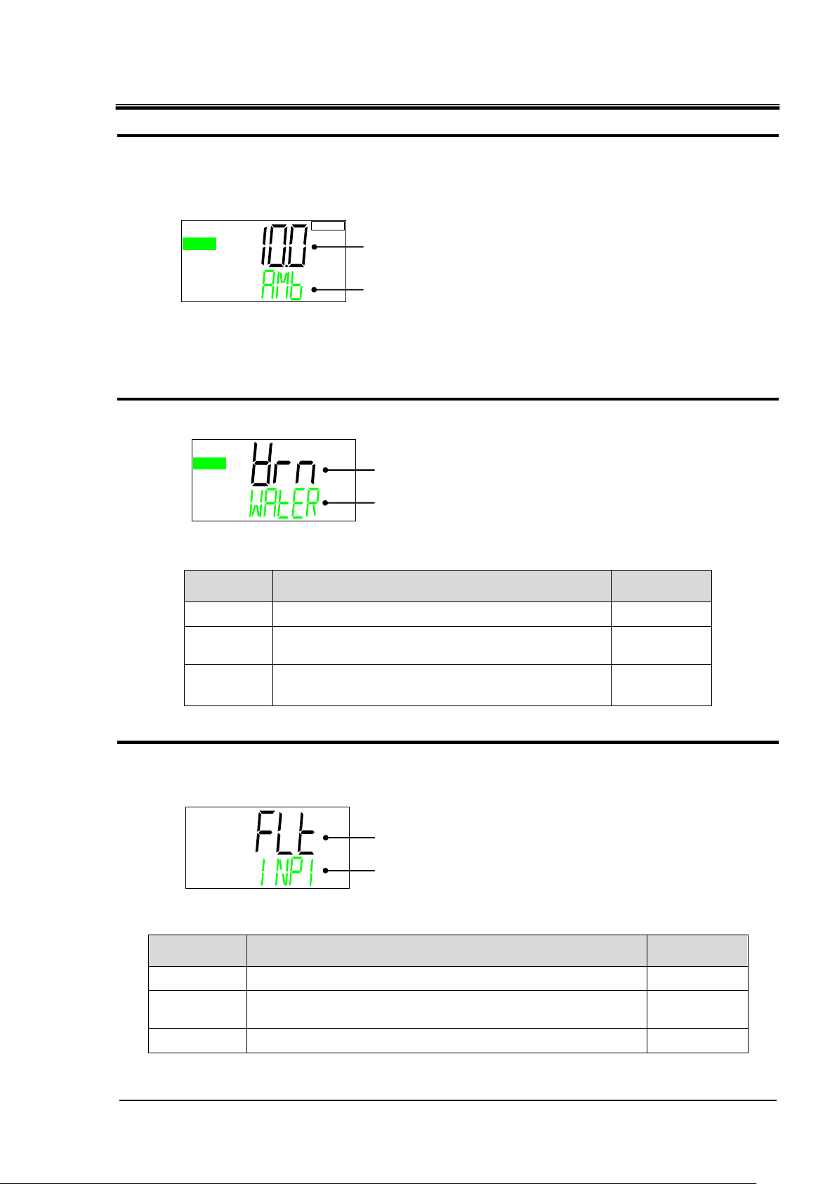
HRX-OM-W002-A
5-39
Set value
Contents
Initial value
OFF
Alarm is not generated.
―
WRN
Operation of this product will continue when the
alarm occurs.
○
FLT
Operation of this product will stop when the alarm
Occurs.
―
Set value
Contents
Initial value
OFF
Alarm is not generated.
―
WRN
Operation of this product will continue when the alarm
occurs.
―
FLT
Operation of this product will stop when the alarm occurs.
○
RUN
℃
AMB ⇒ LOTMP (Alternately displayed)
RUN
Operation of leakage alarm
Operation of the contact input signal 1
INP1 ⇒ ALARM(Alternately displayed)
WATER ⇒ LERK ⇒ ALARM(Alternately displayed)
Ambient temperature lower limit alarm
Chapter 5 Display and Setting of Various Functions
Ambient temperature lower limit alarm
17. Press the [▼] key. Displays screen for setting the lower limit of the ambient
temperature alarm.
Displayed for air-cooled type only. (This item is not displayed for water-cooled type)
Lower limit of alarm AL11: Ambient temperature alarm can be changed.
●Setting range: 5.0 to 40.0℃ (initial value: 10.0℃)
Switching of the leakage alarm
18. Press the [▼] key. Displays screen for setting the leakage alarm operation.
Operation for alarm AL04: Leakage alarm can be selected.
Switching of the contact input signal 1
19. Press the [▼] key. Displays screen for setting the operation of the Contact input signal
1.
Operation for alarm AL25: Contact input signal 1 detection can be selected.
HRR Series 5.5 Advanced setting mode
Page 88

HRX-OM-W002-A
5-40
Set value
Contents
Initial value
OFF
Alarm is not generated.
―
WRN
Operation of this product will continue when the
alarm occurs.
―
FLT
Operation of this product will stop when the alarm
occurs.
○
SEC
SEC
INP1 ⇒ DELAY(Alternately displayed)
INP1 ⇒ OVER(Alternately displayed)
Operation of the contact input signal 2
INP2 ⇒ ALARM(Alternately displayed)
Setting of the contact input signal 1 delay timer for reading
Contact input signal 1 set value of the OFF
detection timer.
Chapter 5 Display and Setting of Various Functions
Contact input signal 1 delay timer for reading
20. Press the [▼] key. Displays screen for setting the Contact input signal 1 Delay timer
for reading.
Time for starting detection of the contact input signal 1 (sec) can be set.
●Setting range: 0 to 300sec. (Initial value: 0sec.)
Contact input signal 1 OFF detection timer
21. Press the [▼] key.Displays screen for setting the OFF detection timer of Contact input
signal 1.
“Alarm AL25: Contact input signal 1 detection” is generated when the set time(sec) passed
from when the contact input signal 1 is not detected.
(When the signal is not detected for the set time, the alarm is generated)
●Setting range: 0 to 10sec. (Initial value: 0sec.)
Switching of the contact input signal 2
22. Press the [▼] key. Displays screen for setting the operation for the Contact input signal
2.
Operation for alarm AL26: Contact input signal 2 detection can be selected.
5.5 Advanced setting mode
HRR Series
Page 89

HRX-OM-W002-A
5-41
Set value
Contents
Initial value
OFF
Alarm is not generated.
―
WRN
Operation of this product will continue when the
alarm occurs.
○
FLT
Operation of this product will stop when the alarm
occurs.
―
SEC
SEC
INP2⇒ DELAY(Alternately displayed)
INP2 ⇒ OVER(Alternately displayed)
Operation for communication error alarm
COMM ⇒ ALARM(Alternately displayed)
Setting of the contact input signal 2 delay
timer for reading
Contact input signal2 set value of the OFF
detection timer.
Chapter 5 Display and Setting of Various Functions
Contact input signal 2 delay timer
23. Press the [▼] key. Displays screen for setting the Contact input signal 2 detection
delay timer for reading.
Time for starting detection of the contact input signal 2 (sec) can be set.
●Setting range: 0 to 300sec. (Initial value: 0sec.)
Contact input signal 2 OFF detection time
24. Press the [▼] key. Displays screen for setting the contact input signal 2 OFF detection
timer.
“Alarm AL26: Contact input signal 2 detection” is generated when the set time(sec) passed
from when the contact input signal 2 is not detected.
(When the signal is not detected for the set time, alarm is generated)
●Setting range: 0 to 10sec. (Initial value: 0sec.)
Switching of communication error alarm
25. Press the [▼] key. Displays screen for setting the communication error alarm
operation.
Operation for alarm AL29: Communication error can be selected.
HRR Series 5.5 Advanced setting mode
Page 90

HRX-OM-W002-A
5-42
SEC
Communication error alarm detection time
COMM ⇒ TIME(Alternately displayed)
SEC
Time for isolated operation of the pump
PUMP ⇒ TIME(Alternately displayed)
Chapter 5 Display and Setting of Various Functions
Communication error alarm detection time
26. Press the [▼] key. Displays screen for setting the communication error alarm detection
time.
Time (sec.) to generate alarm AL29: Communication error can be changed.
●Setting range: 0 to 600sec. (Initial value: 30sec.)
Time for pump to continue operation when alarm is generated.
27. Press the [▼] key. Displays screen for setting the time for the pump to continue
operation when an alarm is generated.
●Setting range: 0 to 9999sec. (Initial value: 0sec.)
Continuation of the pump operation
For some alarms, the pump can continue to operate even when the alarm is
generated by setting this time. The table below shows the alarms for which isolated
pump operation is available.
.
.
Isolated operation of the pump finishes when the one of following conditions is
satisfied.
(1) Pump operation reached the time for isolated operation when alarm is generated.
(2) Pump reached the temperature for isolated operation when alarm is generated.
5.5 Advanced setting mode
HRR Series
Page 91

HRX-OM-W002-A
5-43
℃
PUMP ⇒ TEMP(Alternately displayed)
Upper limit of the circulating fluid temperature for isolated
operation of the pump
Upper line
(White)
Lower line
(Green)
AL01 Low level in tank FLT AL01 LOW⇒LEVEL⇒FLT -
AL02 Low level in tank WRN AL02 LOW⇒LEVE⇒WRN -
AL04 Water leakage
WRN
1
AL04 WATER ⇒ LEAK ○
AL09
Circulating fluid
discharge pressure rise
FLT
2
AL09 HIGH ⇒ PRESS -
AL10 Flow rate decreased
WRN
1
AL10 LOW⇒FLOW⇒WRN ○
AL11
Ambient temperature is
out of the range *3
OFF
1
AL11 AMB⇒TEMP⇒OUT ○
AL12
Electric conductivity
increase *4
WRN AL12 DI ⇒ ERROR -
AL13 NOT TEMP READY
OFF
1
AL13 TEMP⇒READY⇒ERROR ○
AL14
Circulating fluid
temperature increase
OFF
1
AL14 TEMP⇒OUT.HI ○
AL15
Circulating fluid
temperature decrease
OFF
1
AL15 TEMP⇒OUT.LO ○
AL17 Low flow rate FLT AL17 LOW⇒FLOW⇒FLT -
AL18
High circulating fluid
discharge temp.
FLT AL18 TEMP ⇒ FLT -
AL19
High circulating fluid
return temp.
FLT AL19 RET⇒TEMP⇒FLT ○
AL21
High circulating fluid
discharge pressure
FLT AL21 HIGH⇒PRESS⇒FLT -
AL24 Memory error FLT AL24 MEM ⇒ ERROR ○
AL25 Contact input 1
FLT
1
AL25 INP1 ⇒ ERROR ○
AL26 signal detection
FLT
1
AL26 INP2 ⇒ ERROR ○
AL27 Contact input 2 FLT AL27 FORCE ⇒ STOP -
AL28 signal detection
OFF
1
AL28 MANT ⇒ ALARM ○
AL29 Forced stop
WRN
1
AL29 COMM ⇒ ERROR ○
AL30 Notice for maintenance FLT AL30 REF⇒ERROR⇒0000 ○
AL31 Communication error FLT AL31 SENS⇒ERROR⇒0000 -
AL32 Compressor circuit error FLT AL32 CTRL⇒ERROR⇒0000 -
Alarm
no.
Alarm name
Initial
value
Display
Alarms for which isolated
pump operation is
available
Chapter 5 Display and Setting of Various Functions
Table 5.5-1 List of alarms for which isolated pump operation is available
* 1 Select from OFF/ WRN/ FLT 2 Select from WRN/ FLT.
* 3 Can be set only for air-cooled type.
* 4 Option DM (Electric conductivity control type, de-ionized water piping type) only. Alarm is
automatically released when the electric conductivity returns within the range.
Temperature for pump to continue operation when alarm is generated.
28. Press the [▼] key. Displays screen for setting the upper limit of temperature for the
pump to continue operation when an alarm is generated.
●Setting range: 10.0 to 45.0℃ (initial value: 40.0℃)
Refer to P.5-42 “Isolated operation of the pump” for settings.
HRR Series 5.5 Advanced setting mode
Page 92

HRX-OM-W002-A
5-44
Set value
Contents
Initial value
OFF
Alarm is not generated. Only ”X” is displayed
when a notice for maintenance is generated.
○
WRN
Operation of this product will continue when the
alarm occurs.
―
FLT
Operation of this product will stop when the
alarm occurs.
―
Notice for maintenance
MANT ⇒ ALARM(Alternately displayed)
Chapter 5 Display and Setting of Various Functions
Switching of the notice for maintenance
29. Press the [▼] key. Displays screen for setting the switching of the notice for
maintenance. Alarm AL28: Notice for maintenance is generated.
Operation for alarm AL28: Notice for maintenance can be selected.
5.5 Advanced setting mode
HRR Series
Page 93

5-45
Set value
Contents
Initial value
ASC
ASCII mode
○
RTU
RTU mode
―
Set value
Contents
Initial value
485
RS-485
○
232C
RS-232C
―
Communication setting menu TOP screen
Serial protocol.
Communication specification
5.5.5 Communication setting menu
Contact input and serial communication can be performed.
Refer to the Operation Manual Communication Function for more details.
HRX-OM-W002-A
Chapter 5 Display and Setting of Various Functions
Communication setting menu TOP screen
1. When “MENU” key is pressed while Alarm Setting Menu TOP screen is displayed, the
display is changed to the top of “Communication setting menu”.
Serial protocol
2. Press the [▼] key. Displays screen for setting the serial protocol.
Select communication protocol.
Communication specification
3. Press the [▼] key. Displays screen for setting the communication specifications.
Select the communication specification.
HRR Series 5.5 Advanced setting mode
Page 94

HRX-OM-W002-A
5-46
Set value
Contents
Initial value
OFF
No terminal
○
On
With terminal
―
Set value
Contents
Initial value
9.6
9600 bps
―
19.2
19200 bps
○
RS-485 terminal unit
Slave addresses.
SLV ⇒ ADDR(Alternately displayed)
Communication speed
Contact input signal 1 function
DIN1 ⇒ SEL(Alternately displayed)
Chapter 5 Display and Setting of Various Functions
RS-485 terminal unit
4. Press the [▼] key. Displays screen for setting RS-485 terminal unit.
Select RS-485 terminal unit.
Slave addresses
5. Press the [▼] key. Displays screen for setting the slave address.
Sets slave address.
●Setting range: 1 to 32 (Initial value: 1)
Communication speed
6. Press the [▼] key. Displays screen for setting the communication speed.
Selects the communication speed.
Contact input signal 1 Select function
7. Press the [▼] key. Displays screen for setting the function of the Contact input signal 1.
5.5 Advanced setting mode
HRR Series
Page 95

HRX-OM-W002-A
5-47
Set value
Contents
Initial value
OFF
No input signal
○
RNST
Run / stop signal is input
―
RUN
Run signal is input
―
SW
External switch signal input
―
Set value
Contents
Initial value
ALT
Alternate signal
○
mT
Momentary signal
―
Set value
Contents
Initial value
A
N.O. type
○
B
N.C. type
―
Contact input signal 1 type
Contact input signal 1 operation
Contact input signal 2 function
DIN2 ⇒ SEL(Alternately displayed)
DIN1 ⇒ CON ⇒ TYPE(Alternately displayed)
DIN1 ⇒ SW ⇒ TYPE(Alternately displayed)
Chapter 5 Display and Setting of Various Functions
Displays the function for the Contact input signal 1.
Contact input signal 1 type
8. Press the [▼] key. Displays screen for setting the type of Contact input signal 1.
Displays the type of Contact input signal 1.
Contact input signal 1 Operation
9. Press the [▼] key. Displays screen for setting the operation of the Contact input signal
1.
Select the Contact input signal 1 operation.
Contact input signal 2 Select function
10. Press the [▼] key. Displays screen for setting the function of the Contact input signal 2.
HRR Series 5.5 Advanced setting mode
Page 96

HRX-OM-W002-A
5-48
Set value
Contents
Initial value
OFF
No input signal
○
STOP
Stop signal input
―
SW
External switch signal input
―
Set value
Contents
Initial value
ALT
Alternate signal
○
mT
Momentary signal
―
Set value
Contents
Initial value
A
N.O. type
○
B
N.C. type
―
Contact input signal 2 type
Contact input signal 2 operation
Contact output signal 1 function
DOUT1 ⇒ SEL(Alternately displayed)
DIN2 ⇒ CON ⇒ TYPE(Alternately displayed)
DIN2 ⇒ SW ⇒ TYPE(Alternately displayed)
Chapter 5 Display and Setting of Various Functions
Displays the function of the Contact input signal 2.
Contact input signal 2 type
11. Press the [▼] key. Displays screen for setting the type of Contact input signal 2.
Displays the type of Contact input signal 2.
Contact input signal 2 Operation
12. Press the [▼] key. Displays screen for setting the operation of the Contact input signal
2.
Select the Contact input signal 2 operation.
Contact input signal 2 Operation
13. Press the [▼] key. Displays screen for setting the function of the Contact output signal
1.
5.5 Advanced setting mode
HRR Series
Page 97

5-49
Displays the function of the Contact output signal 1.
Set value
Explanation
Initial value
(Default setting)
No output signal
―
Operation status signal output
○
Remote status signal output
―
Unused
―
Ready completion (TEMP READY) signal output
―
TEMP OUT (temperature is out of the range) signal output
―
FLT (operation stop) alarm signal output
―
WRN (operation continue alarm) signal output
―
Notice for maintenance signal output
―
Alarm status signal output
―
Pass through signal of the contact input signal 1
―
Pass through signal of the contact input signal 2
―
Selected alarm status signal output
―
Selected notice for maintenance signal output
―
Set value
Contents
Initial value
A
N.O. type
○
B
N.C. type
―
DOUT ⇒ TYPE(Alternately displayedd)
Contact output signal 1 operation
Contact output signal 1 selected alarm No.
DOUT1 ⇒ ALARM ⇒ CODE(Alternately displayed)
HRX-OM-W002-A
Chapter 5 Display and Setting of Various Functions
Contact output signal 1 Operation
14. Press the [▼] key. Displays screen for setting the operation for the Contact output
signal 1.
Select the Contact output signal 1 operation.
Contact output signal 1 Select alarm
15. Press the [▼] key. Displays screen for setting the selected alarm for the Contact output
signal 1. The alarm is valid when the “selected alarm status signal output” is active.
Select the alarm No. to be allocated to Contact output signal 1
●Setting range:AL.01~AL.32(Default value:AL.01)
HRR Series 5.5 Advanced setting mode
Page 98
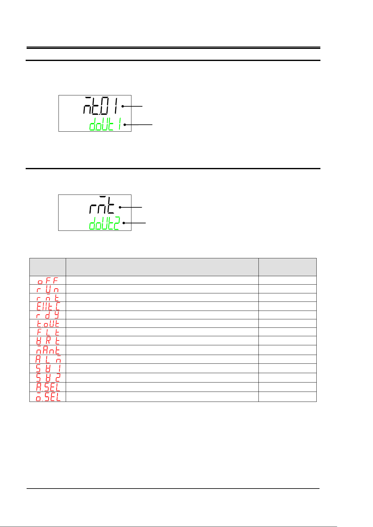
HRX-OM-W002-A
5-50
Set value
Explanation
Initial value
(Default setting)
No output signal
―
Operation status signal output
―
Remote status signal output
○
Unused
―
Ready completion (TEMP READY) signal output
―
TEMP OUT (temperature is out of the range) signal output
―
FLT (operation stop) alarm signal output
―
WRN (operation continue alarm) signal output
―
Notice for maintenance signal output
―
Alarm status signal output
―
Pass through signal of the contact input signal 1
―
Pass through signal of the contact input signal 2
―
Selected alarm status signal output
―
Selected notice for maintenance signal output
―
Contact output signal 1 Selected maintenance alarm No.
Contact output signal 2 function
DOUT2 ⇒ SEL(Alternately displayed)
DOUT1 ⇒ MANT ⇒ CODE(Alternately displayed)
Chapter 5 Display and Setting of Various Functions
Contact output signal 1 Select maintenance
16. Press the [▼] key. Displays screen for setting the selected maintenance for the
Contact output signal 1. The alarm is valid when the “selected maintenance status
signal output” is active.
Select the maintenance alarm No. to be allocated to Contact output signal 1.
●Setting range: MT.01 to MT.05 (Initial value: MT.01)
Contact output signal 2 Select function
17. Press the [▼] key. Displays screen for setting the function for the Contact output signal
2.
Displays the function for the Contact output signal 2.
5.5 Advanced setting mode
HRR Series
Page 99

HRX-OM-W002-A
5-51
Set value
Contents
Initial value
A
N.O. type
○
B
N.C. type
―
DOUT ⇒ SEL(Alternately displayed)
Contact output signal 2 operation
Contact output signal 2 Selected alarm No.
Contact output signal 2 Selected maintenance alarm No.
Contact output signal 3 function
DOUT3 ⇒ SEL(Alternately displayed)
DOUT2 ⇒ ALARM ⇒ CODE(Alternately displayed)
DOUT2 ⇒ MANT ⇒ CODE(Alternately displayed)
Chapter 5 Display and Setting of Various Functions
Contact output signal 2 Operation
18. Press the [▼] key. Displays screen for setting the operation of the Contact output
signal 2.
Select the Contact output signal 2 operation.
Contact output signal 2 Select alarm
19. Press the [▼] key. Displays screen for setting the selected alarm of the Contact output
signal 2.The alarm is valid when the “selected alarm status signal output” is active.
Select the alarm No. to be allocated to Contact output signal 2
●Setting range: AL.01 to AL.32 (Initial value: AL.01)
Contact output signal 2 Select maintenance
20. Press the [▼] key. Displays screen for setting the selected maintenance of the Contact
output signal 2. The alarm is valid when the “selected maintenance status signal output”
is selected.
Select the maintenance alarm No. to be allocated to Contact output signal 2.
●Setting range: MT.01 to MT.05 (Initial value: MT.01)
Contact output signal 3 Select function
21. Press the [▼] key. Displays screen for setting the function of the Contact output signal
3.
HRR Series 5.5 Advanced setting mode
Page 100

HRX-OM-W002-A
5-52
Set value
Contents
Initial value
A
N.O. type
―
B
N.C. type
○
Set value
Explanation
Initial value
(Default setting)
No output signal
―
Operation status signal output
―
Remote status signal output
―
Unused
―
Ready completion (TEMP READY) signal output
―
TEMP OUT (temperature is out of the range) signal output
―
FLT (operation stop) alarm signal output
―
WRN (operation continue alarm) signal output
―
Notice for maintenance signal output
―
Alarm status signal output
○
Pass through signal of the contact input signal 1
―
Pass through signal of the contact input signal 2
―
Selected alarm status signal output
―
Selected notice for maintenance signal output
―
DOUT ⇒ TYPE(Alternately displayed)
Contact output signal 3 operation
Contact output signal 3 Selected alarm No.
DOUT3 ⇒ ALARM ⇒ CODE(Alternately displayed)
Chapter 5 Display and Setting of Various Functions
Displays the function of the Contact output signal 3.
Contact output signal 3 Operation
22. Press the [▼] key. Displays screen for setting the operation of the Contact output
signal 3.
Contact output signal 3 operation
Contact output signal 3 Select alarm
23. Press the [▼] key. Displays screen for setting the selected alarm of Contact output
signal 3. The alarm is valid when the “selected alarm status signal output” is active.
Select the alarm No. to be allocated to Contact output signal 3
●Setting range: AL.01 to AL32 (Initial value: AL01)
5.5 Advanced setting mode
HRR Series
 Loading...