

SMC Networks HRR012-W*-20, HRR018-A*-20, HRR018-W*-20, HRR024-W*-20, HRR030-W*-20 Operation Manual
...
HRX-OM-W004-A
Operation Manual
Communication function
Thermo-chiller
Air-Cooled
refrigerated type
HRR012-A
∗
-20-∗
HRR018-A
∗
-20-∗
HRR024-A
∗
-20-∗
HRR030-A
∗
-20-∗
Water-Cooled
refrigerated type
HRR012-W
∗
-20-∗
HRR018-W
∗
-20-∗
HRR024-W
∗
-20-∗
HRR030-W
∗
-20-∗
Keep this manual available whenever necessary
© 2018 SMC CORPORATION All Rights Reserved

To Users,
Thank you for purchasing SMC’s Thermo chiller (hereinafter referred to as the “product”).
For safety and long life of the product, be sure to read this operation manual (hereinafter referred
to as the “manual”) and clearly understand the contents.
● Be sure to read and follow all instructions noted with “Warning” or “Caution” in this manual.
● This manual is intended to explain the installation and operation of the product. Only people
who understand the basic operation of the product through this manual or who performs
installation and operation of or have basic knowledge about industrial machines are allowed to
work on the product.
● This manual and other documents attached to the product do not constitute a contract, and will
not affect any existing agreements or commitments.
● It is strictly prohibited to copy this manual entirely or partially for the use by the third party
without prior permission from SMC.
Note: This manual is subject to possible change without prior notice.

HRX-OM-W004
Contents
HRR Series
Contents
Chapter 1 Read before using ............................................................. 1-1
1.1 Communication mode and operation method ........................................................ 1-1
1.2 Communication port .................................................................................................. 1-3
1.3 Key operations ........................................................................................................... 1-4
1.4 Parameters ................................................................................................................. 1-8
Chapter 2 Contact input/output communication ............................. 2-1
2.1 Precautions for communication ............................................................................... 2-1
2.1.1 Precautions wiring communication ...................................................................................... 2-1
2.1.2 Precautions after wiring and before communication ............................................................ 2-1
2.2 Communication specification ................................................................................... 2-2
2.3 Connection explanation ............................................................................................ 2-2
2.4 Setting and checking ................................................................................................. 2-3
2.4.1 Setting and checking ............................................................................................................ 2-3
2.4.2 Setting and checking ............................................................................................................ 2-4
2.5 Contact input signal ................................................................................................ 2-12
2.5.1 Run/stop・Run・Stop・External switch signal ....................................................................... 2-13
2.5.2 Signal of the external switch .............................................................................................. 2-14
2.6 Contact output signal .............................................................................................. 2-16
Chapter 3 Serial communication ....................................................... 3-1
3.1 Precautions wiring communication ......................................................................... 3-1
3.2 Connected explanation ............................................................................................. 3-1
3.3 Communication specification ................................................................................... 3-2
3.4 MODBUS communication function .......................................................................... 3-3
3.5 Precautions for communication ............................................................................... 3-3
3.5.1 Precautions after wiring and before communication ............................................................ 3-3
3.5.2 Precautions for communicating ............................................................................................ 3-3
3.6 Setting and checking ................................................................................................. 3-4
3.6.1 Setting and checking items .................................................................................................. 3-4
3.6.2 Setting and checking ............................................................................................................ 3-5
3.7 Communication sequence ........................................................................................ 3-7
3.8 Message configuration .............................................................................................. 3-8
3.8.1 Message frame .................................................................................................................... 3-8
3.9 Function codes .......................................................................................................... 3-9
3.10 Checksum calculation method ............................................................................... 3-10
3.10.1 LRC(ASCII) ........................................................................................................................ 3-10
3.10.2 CRC(RTU) .......................................................................................................................... 3-10
3.11 Explanation of function codes ................................................................................ 3-12
3.11.1 Function code:04 Reading multiple registers .................................................................... 3-12
3.11.2 Function code:06 Writing registers .................................................................................... 3-13
3.11.3 Function code:16 Writing multiple registers ...................................................................... 3-14

HRX-OM-W004
Contents
HRR Series
3.11.4 Function code:23 Reading/writing multiple registers ........................................................ 3-15
3.12 Negative response ................................................................................................... 3-16
3.13 Register Map ............................................................................................................ 3-18
3.13.1 Circulating fluid discharge temperature ............................................................................. 3-19
3.13.2 Circulating fluid flow rate ................................................................................................... 3-19
3.13.3 Circulating fluid discharge pressur .................................................................................... 3-19
3.13.4 Electric conductivity of the circulating fluid ........................................................................ 3-19
3.13.5 Status flag .......................................................................................................................... 3-19
3.13.6 Alarm flag........................................................................................................................... 3-20
3.13.7 Data instruction information ............................................................................................... 3-21
3.13.8 Data display ....................................................................................................................... 3-21
3.13.9 Circulating fluid set temperature ........................................................................................ 3-21
3.13.10 Operation Start Command................................................................................................. 3-21
3.13.11 Serial remote instruction .................................................................................................... 3-21
3.13.12 Data instruction .................................................................................................................. 3-22
Chapter 4 Communication alarm function ....................................... 4-1
4.1 Communication alarm occurs .................................................................................. 4-1
4.2 Communication alarm reset ...................................................................................... 4-2
4.3 Setting and checking ................................................................................................. 4-2
4.3.1 Setting and checking items.................................................................................................. 4-2
4.3.2 Setting and checking ........................................................................................................... 4-3

HRX-OM-W004
Chapter 1 Read before using
HRR Series 1.1 Communication mode and operation method
1-1
Chapter 1 Read before using
The communication of this device consists of contact input/output
communication and serial communication.
The serial communication protocol is a MODBUS communication.
Depending on the customer’s specification, communication can be
changed to contact input/output communication or serial
communication.
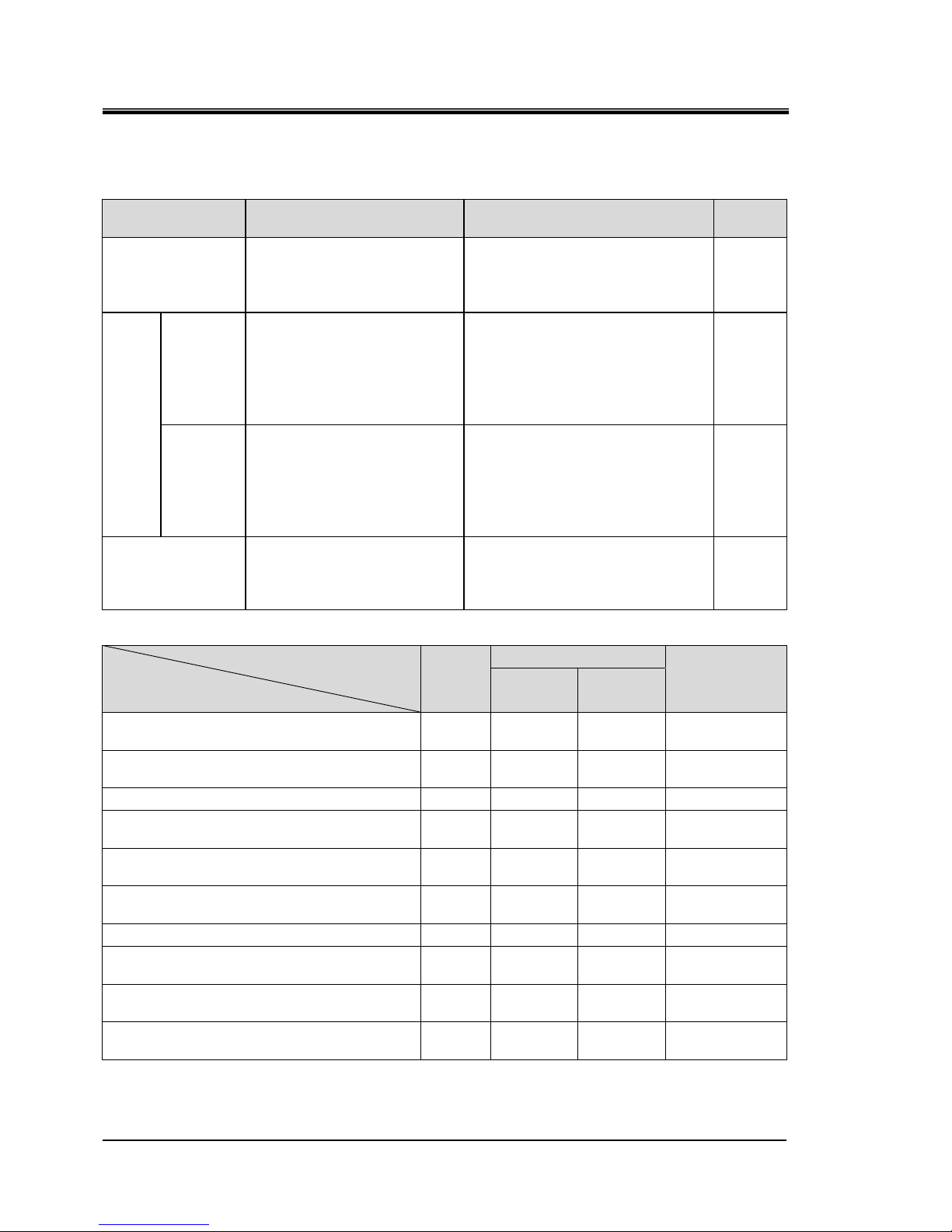
Table 1-1 Communication method
Contact input/output communication.
This product is equipped with a terminal which
runs/stops the product by remote control and a terminal which
can pick up alarm signals. The terminals can be changed
depending on the customer’s application.
Serial
communication
MODBUS standard
protocol
Serial communication (RS-485/RS232C) enables remote
control of run/start of the product, temperature setting, and
details of product condition and alarm condition can be obtained.
●If using contact input/output communication, refer to
chapter 2.
●If using serial communication MODBUS, refer to chapter
3.
1.1 Communication mode and operation method
LOCAL, DIO and SERIAL are available as the communication modes.
Table
1.1-1 explains the communication modes. The default setting is
LOCAL.
The operation method depends on the communication mode. Table
1.1-2 shows how the communication mode and method of operation
are related.
HRX-OM-W004
Chapter 1 Read before using
1.1 Communication mode and operation method
HRR Series
1-2
Table 1.1-1 Communication modes.
Communication
mode
Explanation Setting Display
LOCAL
Run / stop and circulating
fluid temperature setting are
possible with the operation
panel.
Select contact input signal
function 1 selection to "OFF"
(initial setting) / "SW".
None
DIO
REMOTE
Run / stop with contact
input,
and set circulating fluid
temperature on the
operation
panel.
Select contact input signal
function 1 selection as
"RN.ST" / "RUN".
RMT
Lamp
Lighting
up
LOCAL
Run / stop with the operation
panel or contact input.
Set the circulating fluid
temperature on the
operation
panel.
When the operation of the
contact input signal function 1
is selected as "MT" in the state
of DIO REMOTE, it becomes
"DIO LOCAL"
RMT
Lamp
Lighting
up
SERIAL
Run / stop and circulating
fluid temperature setting are
possible with the serial
communication
When serial remote instruction is
valid, this mode is switched.
RMT
Lamp
Lighting
up
Table 1.1-2 Communication mode and operation
LOCAL
DIO
SERIAL
DIO
LOCAL
DIO
REMOTE
Run/Stop control with operation
display panel
○ ○ × ○
Circulating fluid discharge temperature
setting control with operation display panel
○ ○ ○ ×
Except above with operation display panel
○ ○ ○ ○
Condition reading with operation
display panel
○ ○ ○ ○
Run/Stop operation by contact input/output
communication
× ○ ○ ×
Condition reading by contact input/output
communication
○ ○ ○ ○
Reading of the external switch
○ ○∗1 ○∗1 ○
Run/Stop operation by serial
communication.
× × × ○
Circulating fluid discharge temperature
setting control by serial communication.
× × × ○
Condition reading by serial
communication.
○ ○ ○ ○
∗1 Only one external switch can be installed.
HRX-OM-W004
Chapter 1 Read before using
HRR Series 1.2 Communication port
1-3
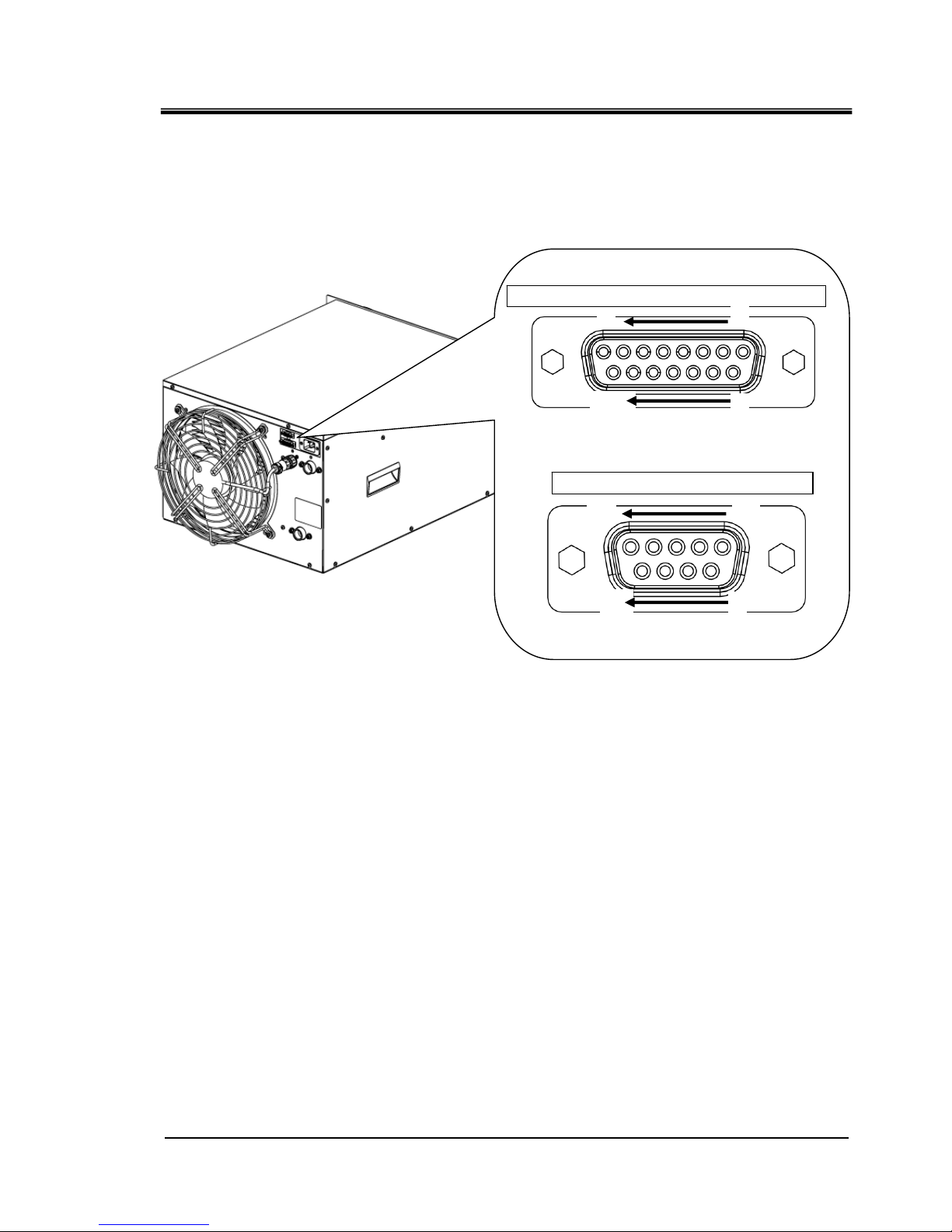
1.2 Communication port
The communication port at the back of the product is used for communication.
Fig 1.2-1 shows the location of the communication port.
Fig 1.2-1 Communication port
Dsub 15 pin female (socket) type
Dsub 9 pin female (socket) type
Connector for contact input / output signal
Serial communication connector
8
1
15
9
5
1
9
6
HRX-OM-W004
Chapter 1 Read before using
1.3 Key operations
HRR Series
1-4
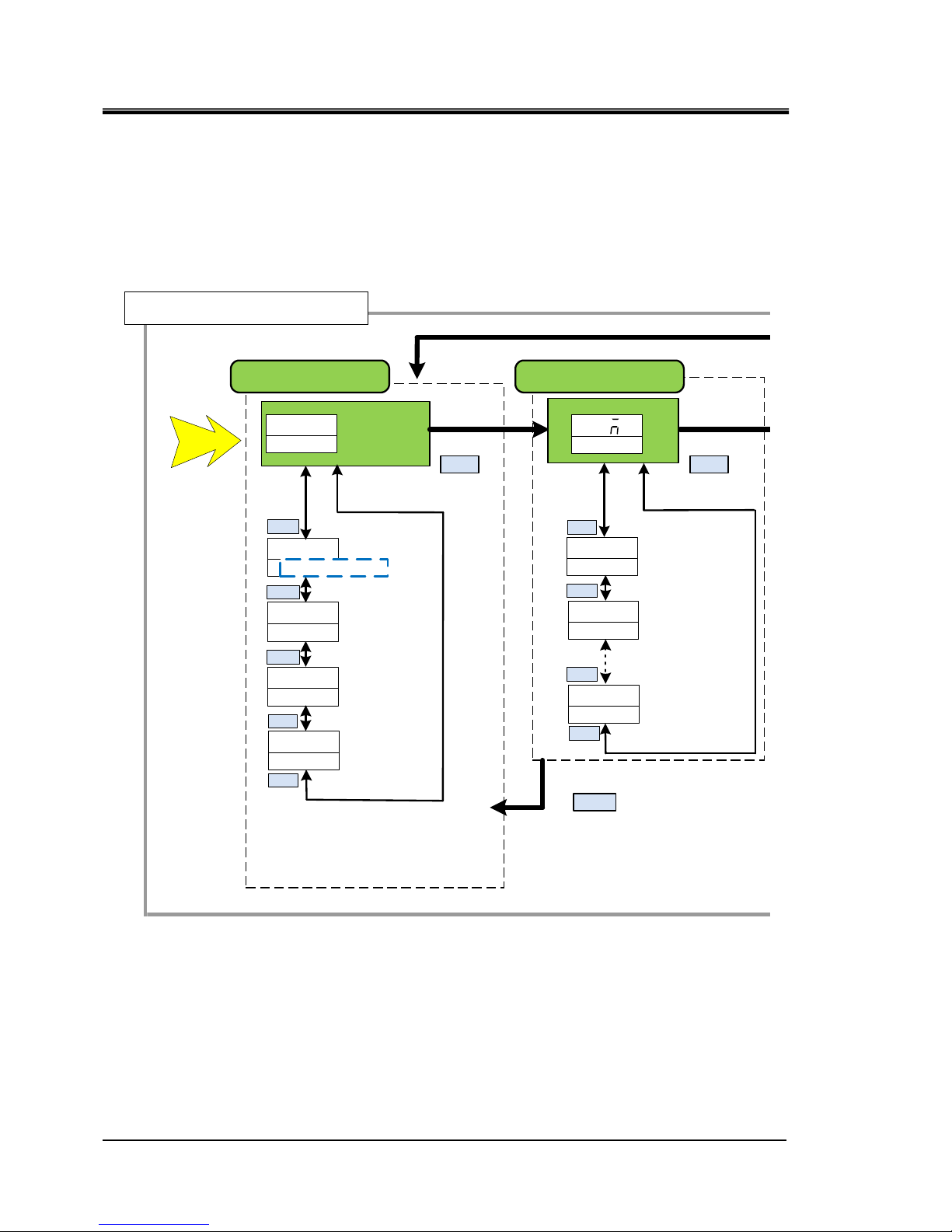
1.3 Key operations
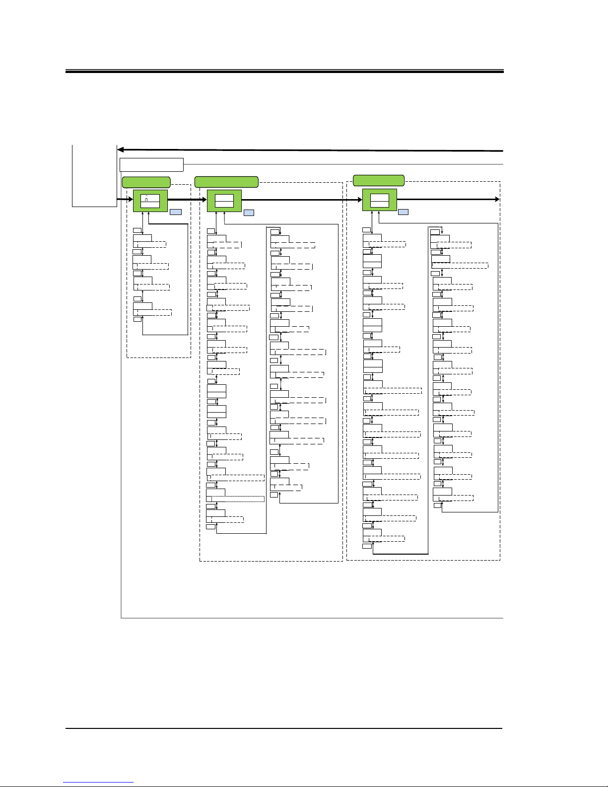
Fig 1.3-1‘’Key operation(1/4)’’ and
Fig1.3-4 ‘’Key operation(4/4)’’ show the operation of keys of the
thermo-chiller. This manual explains the “Communication setting menu”.
Fig 1.3-1 Key operation (1/4)
MENU
Main menu
Power supply ON
Allarm number
(Allarm number
maximum)
Alarm display menu
Allarm number
AL01
Allarm number
(Alarm number minimum)
AL02
ALXX
MENU
AL
XXALM
Basic setting mode
00
circulating fluid return
temp
014
Circulating fluid
outlet pressure
123
DIPV
Electric
conductivity∗
(μS/cm)
PRESS
79
Circulating fluid
flow rate
FLOW
RET ⇔ TEMP
▲/▼
▲/▼
▲/▼
▲/▼
▲/▼
▲/▼
▲/▼
▲/▼
▲/▼
200
200
Circulating fluid
outlet temperature
Circulating fluid set
temperature
∗ Option D【Electric conductivity control function】 only
RESET
Displays only when the alam is generated.
HRX-OM-W004
Chapter 1 Read before using
HRR Series 1.3 Key operations
1-5
Fig 1.3-2 Key operation (2/4)
MENU
Maintenance
notification number
(Maintenance number
maximum)
Maintenance notification menu
Maintenance
notification
number
T01
Maintenance
notification number
(Notification number
Minimum)
TNN
▲/▼
▲/▼
▲/▼
▲/▼
ANT
MENU
T02
Advanced
setting
mode
To switch to 「Advanced setting
mode」 press and hold 「MENU」
key for 5 seconds
MENU
MENU
Press and hold
for approximately
5 second.
Displays only when the maintenance notice is generated.
HRX-OM-W004
Chapter 1 Read before using
1.3 Key operations
HRR Series
1-6
Fig 1.3-3 Key operation (3/4)
EASY mode
resetKey cl ick sound
Electric conductivity
set valve hysteresis*1
Unuse
d
ON
ON
WAKE
250
DISP
50
DIHYS
OFF
EXTMD
PUMPF
00
▲/▼
▲/▼
▲/▼
▲/▼
▲/▼
Key-lock
OFF
▲/▼
Circulating fluid temp time
outside monitoring range
5
WRM
▲/▼
SET
MENU
MENU
KEY ⇒ LOCK
EASY ⇒ MODE
KEY ⇒ CLICK
Offset mode
OFF
▲/▼
OFSET ⇒ MODE
00
▲/▼
OFSET ⇒ TEMP
▲/▼
EXT ⇔ OFSET
TEMP ⇒ OUT ⇒ OVER
DI filter maintenance
time*1
Dustproof filter
maintenance time
*Air-coold type only
5000
FILTT
5000
FUNUP
▲/▼
▲/▼
▲/▼
DI ⇔ TIME
050
5
WRN
HIPRS
HIPRS
HITEM
40
LOFL
5
LOTEM
450
DIHI
ON
ON
OFF
400
Detection time of circulating
fluid discharg e pressure
rise alarm
Changing of the flow
rate decrease alarm
Setting of low flow
rate alarm
Detection time of low
flow rate alarm
Setting of electric
conductivity increase
alarm*1
Switching circulating fluid
temperature drop alarm
Switching circulating fluid
temperature drop alarm
Unused
Unused
Setting of circulating fluid
discharge pressure
rise alarm
▲/▼
▲/▼
▲/▼
▲/▼
▲/▼
▲/▼
▲/▼
▲/▼
▲/▼
▲/▼
FLT
Changing of circulating fluid
discharge pressure
rise alarm
▲/▼
ALST
MENU
▲/▼
MENU
HIPRS ⇒ ALARM
TEMP ⇒ OUTHI ⇒ OUTP
TEMP ⇒ OUTLO ⇒OUTP
AMB ⇒ TEMP ⇒ ALARM
AMB ⇒ HITEMP
Alarm setting menu
FLTR ⇔ TIME
Lower limit of circulati ng
fluid temperature
monitoring function
Circulating fluid temp
monitoring start time
PUMPP
600
WRM
50
▲/▼
▲/▼
TEMP ⇒ OUT ⇒ TYPE
TEMP ⇒ OUT ⇒ START
HIPRS ⇒ TIME
LOFL ⇒ ALARM
LOFL ⇒ TIME
OFF
Switching circulating fluid
temperature range rising
alarm
▲/▼
TEMP ⇒ OUTLO ⇒ ALARM
Alarm buzzer sound
ON
ALARM ⇒ BUZZ
▲/▼
Unused
Pressure of lower
pressure refrigerant
circuit
Pressure of higher
pressu reref rigerant
circuit
000
000
▲/▼
▲/▼
ON
MENU
MENU
REF ⇔ PRSHI
REF ⇔ PRSLO
212
▲/▼
REF ⇔ TEMP
Ambient temperature
*Air-cooled type only
212
AMB ⇔ TEMP
▲/▼
▲/▼
Advance setting mode
0
0
WRN
Contact input signal 2
Delay timer
Contact input signal 2
OFF Detection timer
▲/▼
▲/▼
▲/▼
INP2 ⇒ DELAY
INP2 ⇒ OVER
COMM ⇒ ALARM
Changing of
communication error
monitoring alaarm
OFF
▲/▼
MANT ⇒ ALARM
Changing of
maintenance alarm
Monitor menu
Standard setting menu
Offset temperature
Electric conductivit y set
valve* 1
PUMPF
350
▲/▼
Unuse
d
FLT
Changing of contact
input signal 2 detection
alarm
INP2 ⇒ ALARM
▲/▼
Switching circulating fluid
temperature range rising
alarm
OFF
PUMPF
▲/▼
TEMP ⇒ OUTHI ⇒ ALARM
0
0
INP2
INP2
Contact input signal
1Delay timer of reading
Contact input signal 1
OFF Detection timer
▲/▼
▲/▼
INP1 ⇒ DELAY
FLT
Changing of contact
input signal 1 signal
detection
INP1 ⇒ ALARM
▲/▼
EXT ⇔ CTRL
EXT ⇒ HITMP ⇒ LIMIT
Upper limit of circul ating
fluid temperature
monitoring function
400
▲/▼
TEMP ⇒ OUT ⇒ HITMP
Unused
10
WAKE
Unuse
d
100
▲/▼
EXT ⇒ LOTMP ⇒ LIMIT
EXT ⇔ TIME
▲/▼
Temperature of the
compressor inlet
Basic
setting
mode
10
READY ⇒ HBEND
TEMP READYband
width Upper Limit
▲/▼
-10
▲/▼
READY ⇒ LBRND
TEMP READY Band
width Lower Limit
180
▲/▼
READY ⇒ TIME
TTEMP READY
stabilization time
600
▲/▼
READY ⇒ START
TTEMP READY alarm
monitoring start time
5
▲/▼
TEMP ⇒ OVER
TTEMP READY
Time when it goes away
▲/▼
▲/▼
TEMP READY alarm
OFF
PUMPF
TEMP ⇒ READY ⇒ ALARM
TEMP READY alarm output
added
ON
PUMPF
TEMP ⇒ READY ⇒ OUTP
▲/▼
100
Unused
▲/▼
AMB ⇒ LOTEMP
ARN
Switch leakage alarm
WATER ⇒ LEAK ⇒ ALARM
▲/▼
▲/▼
INP1 ⇒ OVER
30
▲/▼
COMM ⇒ TIME
The monitoring time of
communication error
0
PUMP ⇒ TIME
Time when only pump
rus when alarm is generated
▲/▼
400
PUMP ⇒ TEMP
Temp when only pump
rus when alarm is generated
▲/▼
CTRL
dDI
▲/▼
Electric conductivity
control methhod* 1
DI ⇒ CTRL
Circulating fluid temperature
range increases, the monitoring
method of lowering alarm
RNST
WRM
TEMP ⇒ OUT ⇒ ALARM
▲/▼
HRX-OM-W004
Chapter 1 Read before using
HRR Series 1.3 Key operations
1-7
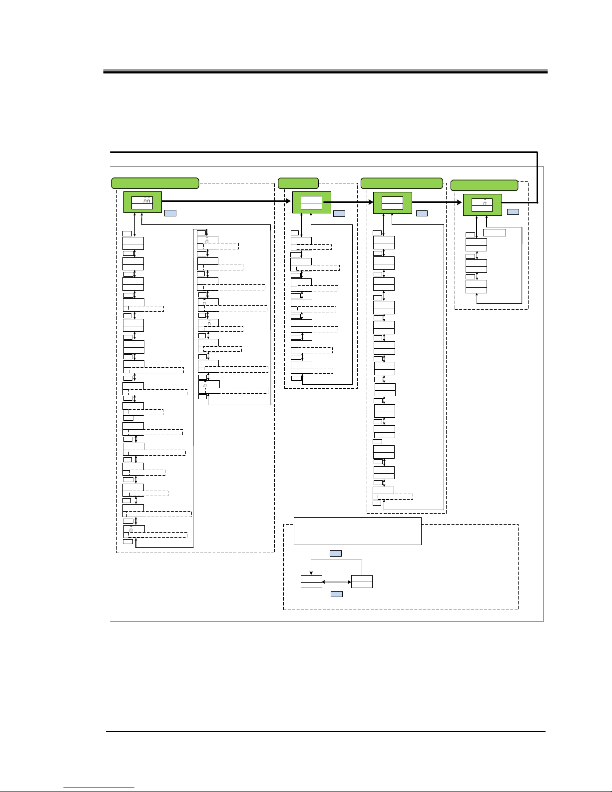
Fig 1.3-4 Key operation (4/4)
ASC
485
OFF
PROT
TYPE
TERM
1
192
SPEED
T01
DIN1
ALT
INP1
Serialprotocol
Communication
specifications
Slave address
Communication speed
RS-485terminal
Digital input signal 1
Selective Maintenance
▲/▼
▲/▼
▲/▼
▲/▼
▲/▼
▲/▼
▲/▼
▲/▼
MENU
OFF
INP2
ALT
INP2
A
INP2
A
OUT1
Digital input
signal 2
operation
Digital output signal 1
operation
Digital input signal 2
function selection
Digital input signal 2 type
▲/▼
▲/▼
▲/▼
▲/▼
A
INP1
Contact inputsignal 1
operation
▲/▼
DIN2 ⇔ SEL
DOUT1 ⇒ TYPE
SLV ⇔ ADDR
NO
MODE
Setting date reset
RST
MENU
MENU
ALL ⇔ RESET
Communication setting menu Reset menu
R T
OUT2
OUT2
AL01
OUT2
AL
OUT3
B
OUT3
AL01
OUT3
Digital output 2
selected alarm
Digital output signal 3
selected alarm
Digital output signal 2
function selection
Digital output signal 2
operation
Digital output signal 3
function selection
Digital output signal 3
operation
▲/▼
▲/▼
▲/▼
▲/▼
▲/▼
▲/▼
DOUT2 ⇔ SEL
DOUT2 ⇔ TYPE
DOUT3 ⇔ SEL
DOUT3 ⇔ TYPE
▲/▼
0
Operation time
Pump operation time
Accumulated operation time
of the dust-proof filter
Accumulated operation
time of the DI filter ∗1
DIT
0
RUNT
0
PUMPT
0
COMPT
0
FLTRT
▲/▼
▲/▼
▲/▼
▲/▼
▲/▼
Compressor
operation time
0
FANT
▲/▼
Fan operation time
*Air-cooled type only
INFO
MENU
Information moniter menu
00
PGVER
Program version
▲/▼
0000
PGNO
Program number
▲/▼
▲/▼
MENU
Digital input
signal 1 type
OUT1
RUN
Digital output signal 1
function selection
▲/▼
DOUT1 ⇒ SEL
OUT1
AL01
Digital output signal 1
selected alarm
DIN1 ⇒ SW ⇒ TYPE
DIN1 ⇒ CON ⇒ TYPE
DIN2 ⇒ SW ⇒ TYPE
DIN2 ⇒ CON ⇒ TYPE
DOUT1 ⇒ ALARM ⇒ CODE
A
▲/▼
DOUT2 ⇒ ALARM ⇒ CODE
OUT1
T01
Digital output 2
selected maintenance
DOUT2 ⇒ MANT ⇒ CODE
OUT1
T01
Digital output 3
selected maintenan ce
DOUT3 ⇒ MANT ⇒ CODE
DOUT3 ⇒ ALARM ⇒ CODE
▲/▼
▲/▼
DOUTI⇒ MANT ⇒ CODE
aAL h
nnn
Alarm history menu
MENU
AL17
Alarm
(The latest)
▲/▼
OFF
DINI
▲/▼
Digital input signal 1
function selection
hRR
018-R
Model
▲/▼
20-
DMTU
Power Options
▲/▼
Example
AL10
Alarm
▲/▼
ALNN
Alarm
(The oldest)
▲/▼
*1:With electric conductivity
control function only
0
Number of times of
momentary power failure
POWF
▲/▼
NO
NO
PROT
Reset of dust-proof
filter operation time
DI filter
Reset usage time
▲/▼
▲/▼
FLTRT ⇒ RESET
DIT ⇒ RESET
▲/▼
NO
PROT
Reset of pump
operation time
▲/▼
PUMPT ⇒ RESET
NO
PROT
Reset of compressor
operation time
▲/▼
COMPT ⇒ RESET
NO
PROT
Reset of fan
operation time
▲/▼
FANT ⇒ RESET
OFF
Forced DI solenoid
valve
open
DI ⇒ VALVE
0000
instantaneous power failure
occurrence count
DIT
▲/▼
▲/▼
▲/▼
CO
MENU
STD
WS001
standard product/
special numbers
▲/▼
SELIAL.NO
*2
By pressing the ENT key on each alarm history screen,
accumulated operating time and the number of
historcases at the time of occurrence are displayed.
AL10
123
NO2
MENU
ENT
Accumulated operating time at alarm accurrence is displayed
Alarm log number
COMM ⇒ STUS

HRX-OM-W004
Chapter 1 Read before using
1.4 Parameters
HRR Series
1-8
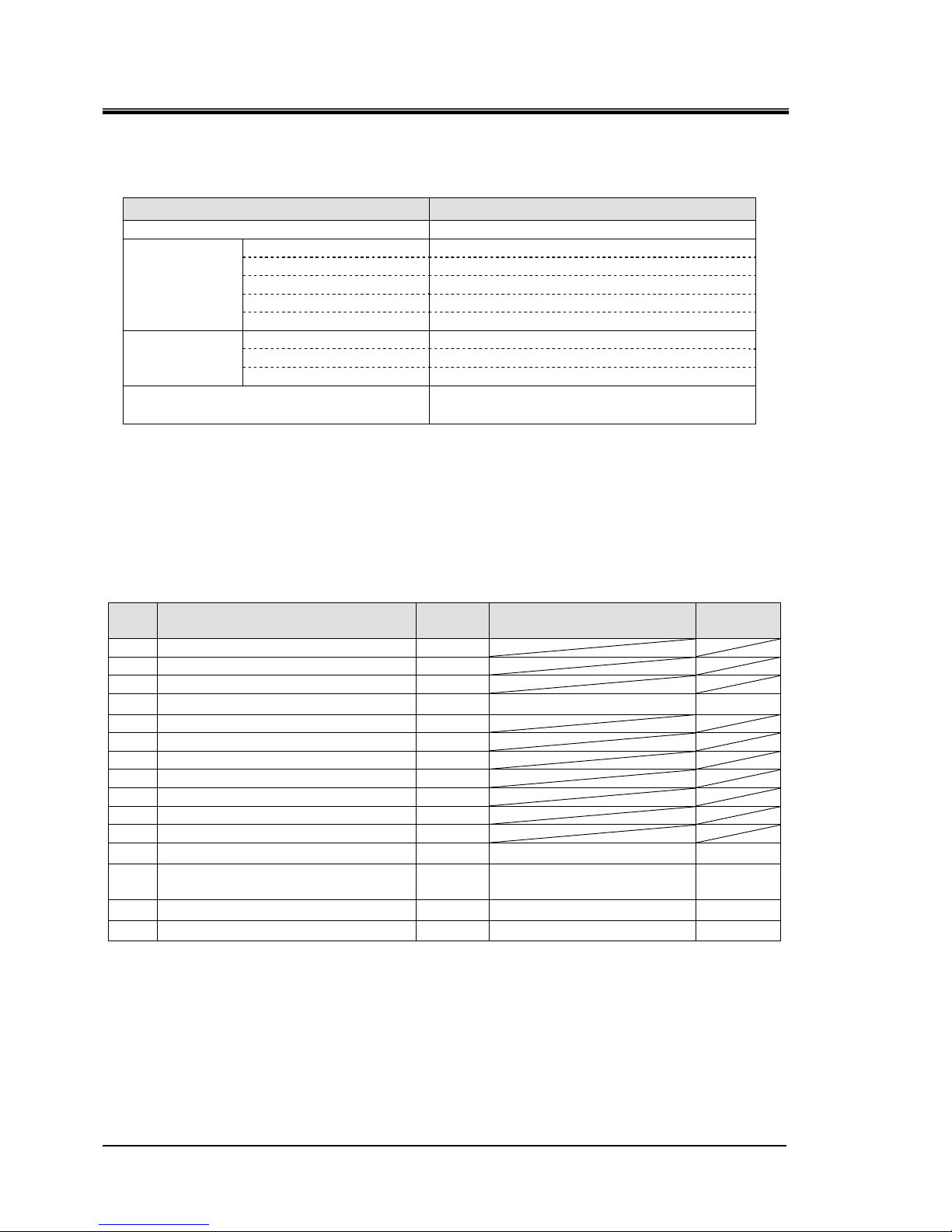
1.4 Parameters
Table 1.4-1 ‘’Communication setting menu Parameters’’ explains the
parameters of the 「communication setting menu」.
Table 1.4-1 Communication setting menu Parameters
∗1 Selectable from OFF/RUN/RMT/EXT.C/RDY/T.OUT/FLT/WRN/MENT/ALM/SW1/SW2/A.SEL/M.SEL
Initial value Select/setting range
TOP
screen
-
COMM
-
MEN U -
No.1
screen
Serial protocol
ASC AS C/ RTU PR OT
No.2
screen
Communic ation specification
485 485/232C TYPE
No.3
screen
RS-485 terminal unit
OFF OFF/ON TERM
No.4
screen
Slave address
11
~
32 SLV ⇒ ADDR
No.5
screen
Communic ation speed
(
bps
)
19.2 9.6/19.2 SPEED
No.6
screen
Contact input signal 1 function OFF OFF/RN.ST/RUN/SW D.IN1 ⇒ SEL
No.7
screen
Contact input signal 1 type ALT ALT/MT D.IN 1 ⇒ SW ⇒ TYPE
No.8
screen
Contact input signal 1 operation A A/B D.IN1 ⇒ CON ⇒ TYPE
No.9
screen
Contact input signal 2 function OFF OFF/STOP/SW D.IN2 ⇒ SEL
No.10
screen
Contact input signal 2 type ALT ALT/MT D.IN 2 ⇒ SW ⇒ TYPE
No.11
screen
Contact input signal 2 operation A A/B D.IN2 ⇒ CON ⇒ TYPE
No.12
screen
Contact output signal 1 function RUN
∗
1D.OUT1
⇒
SEL
No.13
screen
Contact output signal 1 operation A A/B D.OUT1 ⇒ TYPE
No.14
screen
Contact output signal 1
alarm
AL.01 AL.01~AL .32 D .OU T1 ⇒ ALARM ⇒ CODE
No.15
screen
Contact output signal 1 maintenance MT.01 MT.01~MT. 05 D.O UT1⇒ MANT ⇒ CODE
No.16
screen
Contact output signal 2 function RMT
∗
1D.OUT2
⇒
SEL
No.17
screen
Contact output signal 2 operation A A/B D.OUT2 ⇒ TYPE
No.18
scree
Contact output signal 2
alarm
AL.01 AL.01~AL .32 D .OU T2 ⇒ ALARM ⇒ CODE
No.19
screen
Contact output signal 2 maintenance MT.01 MT.01~MT.05 D.OUT2 ⇒ MANT ⇒ CODE
No.20
screen
Contact output signal 3 function ALM
∗
1D.OUT3
⇒
SEL
No.21
screen
Contact output signal 3 operation B A/B D.OUT3 ⇒ TYPE
No.22
screen
Contact output signal 3
alarm
AL.01 AL.01~AL .32 D .OU T3 ⇒ ALARM ⇒ CODE
No.23
screen
Contact output signal 3 maintenance MT.01 MT.01~MT.05 D.OUT3 ⇒ MANT ⇒ CODE
3.5.2
2.4.2
ScreenNo. Item
Display unit
Reference
page
Upper stage(White
)
Lower stage
(
Green
)

HRX-OM-W004
Chapter 2 Contact input/output communication
HRR Series 2.1 Precautions for communication
2-1
Chapter 2 Contact input/output
communication
The device is equipped with a terminal which runs/stops the product. It is also
equipped with a terminal which picks up operation signals, alarm signals and
setting condition.
The device starts contact input/output communication according to the setting
of the operation display panel. Contact input/output communication can be
customized by changing the settings. Table 2-1 ‘’Customizable content’’
shows the contents which can be changed by the operation display panel.
Table 2-1 Customizable content
Signal Can be changed
Contact input signal (2pcs.) Signal configuration (Alternate/Momentary)
Contact output signal (3pcs.) Type of signal, signal operation (N.O type / N.C type)
2.1 Precautions for communication
2.1.1 Precautions wiring communication
○Communication wiring
A communication cable that connects the product and customer system is not
included with the product. Please prepare a cable, referring to 2.3
“Connection explanation“. In order to avoid malfunction, do not connect to
any place other than those shown in 2.3 “Connection explanation“.
○Power supply
To use the power of the product, the total load current must be 500mA or
less.
2.1.2 Precautions after wiring and before communication
○Check or set the communication mode by the operation display panel.
・Communication mode shall be DIO.
Other modes can perform reading, but only DIO mode can perform writing.
HRX-OM-W004
Chapter 2 Contact input/output communication
2.2 Communication specification HRR Series
2-2
2.2 Communication specification
Table 2.2-1 DIO Communication specification
Item Specification
Connector type(for this product) Dsub 15P type female connector
Contact input
signal
Insulation system
Photo coupler
Rated input voltage
DC24V
Used input voltage
DC 21.6 to 26.4V
Rated input current
5mA TYP
Input signal
4.7kΩ
Contact output
signal
Rated load voltage
AC48V or less/DC30V or less
Maximum load current
AC/DC 500mA (Resistance load)
Minimum load current DC5V 10mA
DC24V output voltage
DC24V±10% 500mA MAX
(It can not be used for inductive load.)
2.3 Connection explanation
This part explains the port of the contact input/output communication. A
communication cable that connects the product and customer system is not
included with the product.
Table 2.3-1 Contact input/output pin number
PIN
no
Application Division Default setting
Setting
available
1 DC 24V output Output
2 DC 24V output Output
3 DC 24V output Output
4 Contact input signal 1 Input None
○
5 Common of contact output signal 1 Output
6 Common of contact output signal 2 Output
7 Common of contact output signal 3 Output
8 None -
9 24 COM output Output
10 24 COM output Output
11 Common of contact input signal Output
12 Contact input signal 2 Input None
○
13 Contact output signal 1 Output
Run status signal
(N.O. type)
○
14 Contact output signal 2 Output Remote signal (N.O. type)
○
15 Contact output signal 3 Output Alarm signal (N.C. type)
○
HRX-OM-W004
Chapter 2 Contact input/output communication
HRR Series 2.4 Setting and checking
2-3
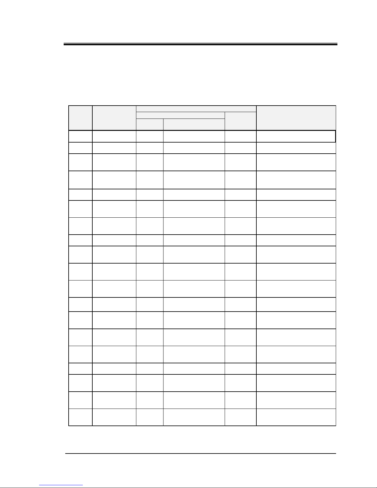
2.4 Setting and checking
2.4.1 Setting and checking
The table below explains the setting items of the contact input/output signal
and the initial values.
Table 2.4-1 List of set communication items
*1:Selectable from OFF/RUN/RMT/EXT.C/RDY/T.OUT/FLT/WRN/MENT/ALM/SW1/SW2/
A.SEL/M.SEL
Initial
va lu e
Select/setting range
TOP
screen
-
COMM
-
MEN U
Com m un icati on s etting m enu
TOP screen
No.6
screen
Contact input
signal 1 function
OFF OFF/RN .ST/R UN /SW
D.IN1
⇒
SEL
Setting function of contact input
signal 1.
No.7
screen
Contact input
signal 1 type
AL T AL T/MT
D.IN1
⇒
SW
⇒
TYPE
Setting input type of contact
input signal 1.
No.8
screen
Contact input
signal 1
operation
AA/B
D.IN1
⇒
CON
⇒
TYPE
Setting input operation of
contact input signal 1.
No.9
screen
Contact input
signal 2 function
OFF OFF/STOP/SW
D.IN2
⇒
SEL
Setting function of contact input
signal 2.
No.10
screen
Contact input
signal 2 type
AL T AL T/MT
D.IN2
⇒
SW
⇒
TYPE
Setting input type of contact
input signal 2.
No.11
screen
Contact input
signal 2
operation
AA/B
D.IN2
⇒
CON
⇒
TYPE
Setting input operation of
contact input signal 2.
No.12
screen
Contact output
signal 1 function
RUN
※
1
D.OUT1
⇒
SEL
Setting function of contact input
signal 1.
No.13
screen
Contact output
signal 1
operation
AA/B
D.OUT1
⇒
TYPE
Setting output operation of
contact output signal 1.
No.14
screen
Contact output
signal 1alarm
AL .0 1 AL .0 1~AL .3 2
D.OUT1
⇒
ALARM
⇒
CODE
Setting selected alarm of
contact output signal 1.
No.15
screen
Contact output
signal 1
maintenance
MT. 01 MT. 01~MT. 05
D.OUT1
⇒
MANT
⇒
CODE
Setting selected maintenance of
contact output signal 1.
No.16
screen
Contact output
signal 2 function
RMT
※
1
D.OUT2
⇒
SEL
Setting function of contact output
signal 2.
No.17
screen
Contact output
signal 2
operation
AA/B
D.OUT2
⇒
TYPE
Setting output operation of
contact output signal 2.
No.18
screen
Contact output
signal 2 alarm
AL .0 1 AL .0 1~AL .3 2
D.OUT2
⇒
ALARM
⇒
CODE
Setting selected alarm of
contact output signal 2.
No.19
screen
Contact output
signal 2
maintenance
MT. 01 MT. 01~MT. 05
D.OUT2
⇒
MANT
⇒
CODE
Setting selected maintenance of
contact output signal 2.
No.20
screen
Contact output
signal 3 function
AL M
※
1
D.OUT3
⇒
SEL
Setting function of contact output
signal 3.
No.21
screen
Contact output
signal 3
operation
BA/B
D.OUT3
⇒
TYPE
Setting output operation of
contact output signal 3.
No.22
screen
Contact output
signal 3 alarm
AL .0 1 AL .0 1~AL .3 2
D.OUT3
⇒
ALARM
⇒
CODE
Setting selected alarm of
contact output signal 3.
No.23
screen
Contact output
signal 3
maintenance
MT. 01 MT. 01~MT. 05
D.OUT3
⇒
MANT
⇒
CODE
Setting selected maintenance of
contact output signal 3.
Display
No.
Item
Display unit
Contents
Upper stage(White
)
Lower
stage
(
Green
)
HRX-OM-W004
Chapter 2 Contact input/output communication
2.4 Setting and checking HRR Series
2-4
2.4.2 Setting and checking
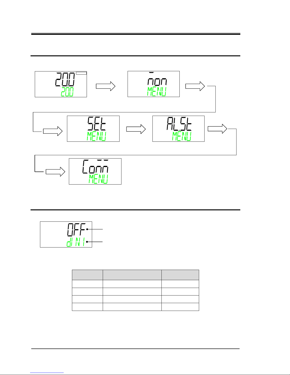
Communication setting menu TOP screen
1. Displays communication setting menu.
Contact input signal 1 function
2. Press the [▼] key. Displays screen for setting the function of the Contact input signal 1
Displays the function for the Contact input signal 1.
Set value Contents
Initial value
OFF
No input signal
○
RNST
Run / stop signal is input
―
RUN
Run signal is input
―
SW
External switch signal input
―
℃
Main menu
TOP
screen
[MENU] key
Press and hold
(5 seconds)
Monitor Menu
TOP
screen
[MENU]
key
Standard setting menu
TOP
screen
[MENU]
key
Alarm setting menu
TOP
screen
Communication setting menu
TOP
screen
[MENU]
key
[MENU]
key
[MENU]
key
Contact input signal 1 function
DIN1 ⇒ SEL(Alternately displayed)
HRX-OM-W004
Chapter 2 Contact input/output communication
HRR Series 2.4 Setting and checking
2-5
Contact input signal 1 type
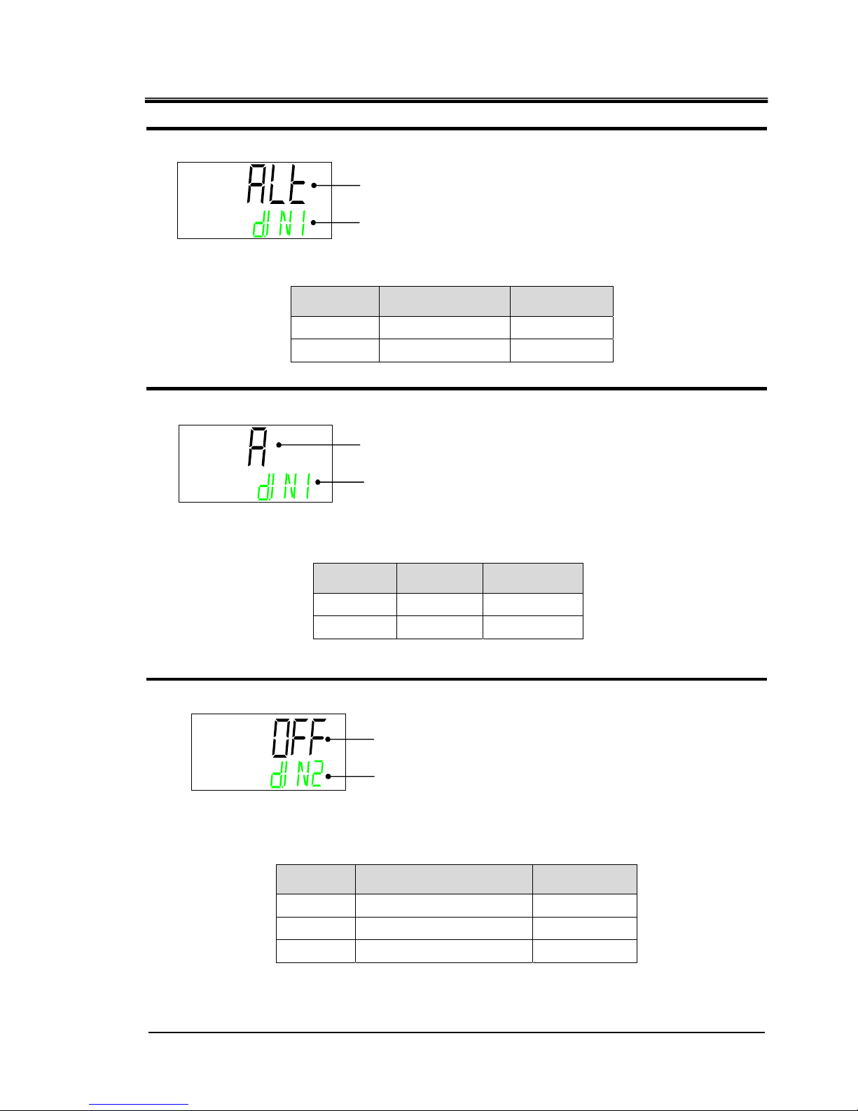
3. Press the [▼] key. Displays screen for setting the type of Contact input signal 1.
Displays the type of Contact input signal 1.
Contact input signal 1
operation
4. Press the [▼] key. Displays screen for setting the operation of the Contact input signal 1.
Select the Contact input signal 1 operation.
Contact input signal 2 Select function
5. Press the [▼] key. Displays screen for setting the function of the Contact input signal 2.
Displays the function of the Contact input signal 2.
Set value Contents
Initial value
OFF
No input signal
○
STOP
Stop signal input
―
SW
External switch signal input
―
Set value Contents
Initial value
ALT
Alternate signal
○
mT
Momentary signal
―
Set value Contents
Initial value
A
N.O. type
○
B
N.C. type
―
Contact input signal 1 type
DIN1 ⇒ SW ⇒ TYPE(Alternately displayed)
Contact input signal 1 operation
DIN1 ⇒ CON ⇒ TYPE(Alternately displayed)
Contact input signal 2 function
DIN2 ⇒ SEL(Alternately displayed)
HRX-OM-W004
Chapter 2 Contact input/output communication
2.4 Setting and checking HRR Series
2-6
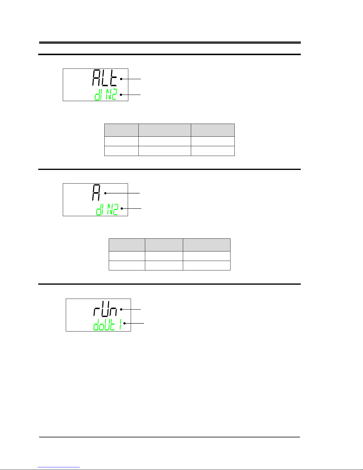
Contact input signal 2 type
6. Press the [▼] key. Displays screen for setting the type of Contact input signal 2.
Displays the type of Contact input signal 2.
Set value Contents
Initial value
ALT
Alternate signal
○
mT
Momentary signal
―
Contact input signal 2 operation
7. Press the [▼] key. Displays screen for setting the operation of the Contact input signal 2.
Select the Contact input signal 2 operation.
Set value Contents
Initial value
A
N.O. type
○
B
N.C. type
―
Contact output signal 1 function
8. Press the [▼] key. Displays setting screen for function of contact output signal 1 .
Displays the function of the Contact output signal 1.
Contact input signal 2 type
DIN2 ⇒ SW ⇒ TYPE(Alternately displayed)
Contact input signal 2 operation
DIN2 ⇒ CON ⇒ TYPE(Alternately displayed)
Contact output signal 1 function
DOUT1 ⇒ SEL(Alternately displayed)
 Loading...