

SMC Networks HRL300-A*-20 Series, HRL Series, HRL200-A*-20 Series, HRL100-A*-20 Series Operation Manual
Page 1
HRX-OM-W060
Original Instructions
Thermo Chiller
HRL Series
HRL100-A-20
HRL200-A-20
HRL300-A-20
Operation Manual
Installation ・ Operation
Keep this manual available whenever necessary
© 2019 SMC CORPORATION All Rights Reserved
Page 2

Note: This manual is subject to possible change without prior notice.
To the users
Thank you for purchasing SMC’s Thermo chiller (hereinafter referred to as the “product”).
For safety and long life of the product, be sure to read this operation manual (hereinafter referred to as the
“manual”) and clearly understand the contents.
● Be sure to read and follow all instructions noted with “Warning” or “Caution” in this manual.
● This manual is intended to explain the installation and operation of the product. Only people who
understand the basic operation of the product through this manual or who perform installation and
operation of or have basic knowledge about industrial machines are allowed to work on the product.
● This manual and other documents attached to the product do not constitute a contract, and will not
affect any existing agreements or commitments.
● It is strictly prohibited to copy this manual entirely or partially for the use by a third party without prior
permission from SMC.
Page 3

HRX-OM-W060
Contents
Contents
Chapter 1 Safety Instructions ........................................................... 1-1
1.1 Before Using the Product ....................................................................................... 1-1
1.2 Reading the Manual ................................................................................................ 1-1
1.3 Hazards .................................................................................................................... 1-2
1.3.1 Level of hazards ................................................................................................................... 1-2
1.3.2 Definition of “Serious injury” and “Minor injury” .................................................................... 1-2
1.4 Product Label .......................................................................................................... 1-3
1.5 Safety Measures ...................................................................................................... 1-4
1.5.1 Safety instructions for use .................................................................................................... 1-4
1.5.2 Personal protective equipment ............................................................................................ 1-4
1.6 Emergency Measures.............................................................................................. 1-5
1.7 Waste Disposal ........................................................................................................ 1-5
1.7.1 Disposal of refrigerant and compressor oil .......................................................................... 1-5
1.7.2 Disposal of product .............................................................................................................. 1-5
1.8 Safety Data Sheet(SDS) ......................................................................................... 1-6
Chapter 2 Name and Function of Parts ............................................ 2-1
2.1 Model Number of Product ....................................................................................... 2-1
2.2 Name and Function of Parts ................................................................................... 2-2
2.2.1 HRL-A-20 (Air cooled type) ........................................................................................... 2-2
2.3 Function of Parts ..................................................................................................... 2-4
Chapter 3 Transport and Setting Up ................................................. 3-1
3.1 Transport.................................................................................................................. 3-1
3.1.1 Transportation using forklift and hanging ............................................................................. 3-2
3.1.2 Transportation using casters ................................................................................................ 3-3
3.2 Installation ............................................................................................................... 3-4
3.2.1 Environment ......................................................................................................................... 3-4
3.2.2 Location ................................................................................................................................ 3-6
3.2.3 Installation and maintenance space ..................................................................................... 3-7
3.3 Installation ............................................................................................................... 3-8
3.3.1 Installation ............................................................................................................................ 3-8
3.3.2 Electrical wiring ..................................................................................................................3-10
3.3.3 Preparation and wiring of power supply cable ...................................................................3-12
3.3.4 Contact input/output communicatin wiring .........................................................................3-17
3.3.5 Wiring of Run/Stop signal input ..........................................................................................3-21
3.3.6 Wiring of contact output signal ...........................................................................................3-23
3.3.7 Wiring of analog output signal ............................................................................................3-24
3.3.8 RS-485 communication wiring ...........................................................................................3-24
3.3.9 RS-232C communication wiring .........................................................................................3-26
3.4 Piping ..................................................................................................................... 3-28
■ How to connect to the drain port.................................................................................................3-34
3.5 Circulating Fluid Supply ....................................................................................... 3-36
HRL Series
Page 4

HRX-OM-W060
Contents
Chapter 4 Starting the Product ......................................................... 4-1
4.1 Before Starting ......................................................................................................... 4-1
4.2 Preparation for Start ................................................................................................ 4-2
4.2.1 Power supply ....................................................................................................................... 4-2
4.2.2 Operation screen (home screen) ......................................................................................... 4-3
4.3 Preparation of Circulating Fluid Supply to User's Equipment .............................. 4-4
4.4 Operation Start and Stop ......................................................................................... 4-6
4.4.1 Setting of circulating fluid temperature ................................................................................ 4-6
4.4.2 Setting of pump operation mode ......................................................................................... 4-7
4.4.3 Starting the Product ............................................................................................................. 4-7
4.4.4 Stopping the product ........................................................................................................... 4-8
4.5 Check Items during Startup .................................................................................... 4-9
4.6 Adjustment of Circulating Fluid Flow Rate ............................................................ 4-9
Chapter 5 Display and Setting of Various Functions ...................... 5-1
5.1 Basic Operation ....................................................................................................... 5-1
5.1.1 Touch panel ......................................................................................................................... 5-1
5.1.2 Basic operating instructions................................................................................................. 5-2
5.2 Flow Chart of Operation Screen.............................................................................. 5-4
5.2.1 Flow Chart of Operation Screen .......................................................................................... 5-4
5.3 List of Functions ...................................................................................................... 5-7
5.4 Description of Screen .............................................................................................. 5-8
5.4.1 Home screen ....................................................................................................................... 5-8
・Menu key .......................................................................................................................................... 5-9
・Display and setting of date and time ................................................................................................ 5-9
・Operating condition display .............................................................................................................. 5-9
・Current circulating fluid temperature PV ........................................................................................ 5-10
・Circulating fluid set temperature SP .............................................................................................. 5-10
・Circulating fluid discharge pressure Press PV ............................................................................... 5-11
・Circulating fluid flow rate Flow PV.................................................................................................. 5-11
・Circulating fluid flow rate DI PV...................................................................................................... 5-11
・Independent pump operation Pump ............................................................................................... 5-12
・Operation mode MODE .................................................................................................................. 5-12
・RUN/STOP display ......................................................................................................................... 5-12
・Run/stop operation ......................................................................................................................... 5-13
5.4.2 Menu .................................................................................................................................. 5-14
5.4.3 Status screen ..................................................................................................................... 5-14
5.4.4 Information screen ............................................................................................................. 5-16
・Alarm reset ..................................................................................................................................... 5-17
・Alarm name .................................................................................................................................... 5-17
・Alarm log record ............................................................................................................................. 5-18
・Display of alarm/maintenance reminder ........................................................................................ 5-19
5.4.5 Check operation time screen and maintenance reminder ................................................. 5-20
・Setting the usage time of DI filter ................................................................................................... 5-21
HRL Series
Page 5

HRX-OM-W060
Contents
・Setting of the usage time of dustproof filter ....................................................................................5-21
5.4.6 Software version screen .....................................................................................................5-22
5.4.7 CH1 setting screen .............................................................................................................5-22
・Temperature rise/drop alarm (AL10/AL11)......................................................................................5-23
・TEMP READY alarm (AL12) of TEMP READY function .................................................................5-25
・Offset (TEMP OFFSET) function ....................................................................................................5-28
・Pump operation mode ....................................................................................................................5-31
・Discharge pressure alarm (AL18/AL19/AL20) ................................................................................5-32
5.4.8 CH2 setting screen .............................................................................................................5-34
・Temperature rise/drop alarm (AL14/AL15) setting ..........................................................................5-35
・TEMP READY alarm (AL16) of TEMP READY function .................................................................5-36
・Offset (TEMP OFFSET) function ....................................................................................................5-38
・Pump operation mode ....................................................................................................................5-39
・Discharge pressure alarm (AL21/AL23/AL24/AL26) ......................................................................5-40
・Electric conductivity and alarm setting (AL27) ................................................................................5-41
5.4.9 Function setting screen ......................................................................................................5-43
・Key-lock, startup operating method, anti-freezing and warming-up ...............................................5-44
・Continuing pump operation .............................................................................................................5-45
・Ambient temperature alarm (AL35) and maintenance alarm (AL36) ..............................................5-48
・TEMP OUT signal ...........................................................................................................................5-49
・Data reset .......................................................................................................................................5-50
5.4.10 Communication setting screen ...........................................................................................5-51
・Setting for communication error (AL34)/contact input signal detection (AL30 and AL31) ..............5-52
・Serial communication setting ..........................................................................................................5-53
・Setting of analog output signal .......................................................................................................5-55
・Setting of contact input signal form.................................................................................................5-55
・Setting of contact output signal 1 to 3 ............................................................................................5-57
・Setting of contact output signal 4 to 6 ............................................................................................5-57
5.4.11 Temperature waveform screen...........................................................................................5-62
Chapter 6 Alarm Notification and Troubleshooting ........................ 6-1
6.1 Alarm Notification ................................................................................................... 6-1
6.2 Operation of this product when an alarm occurs ................................................. 6-1
6.3 Troubleshooting ...................................................................................................... 6-2
6.3.1 Alarm contents, causes, and troubleshooting ...................................................................... 6-2
6.4 Other Errors ............................................................................................................. 6-5
Chapter 7 Control, Inspection and Cleaning ................................... 7-1
7.1 Quality Control of Circulating Fluid and Facility Water ................................ ........ 7-1
7.2 Inspection and Cleaning ......................................................................................... 7-2
7.2.1 Daily check ........................................................................................................................... 7-2
7.2.2 Monthly check ...................................................................................................................... 7-3
7.2.3 Inspection every 3 months ................................................................................................... 7-4
7.3 Operation Stop for an Extended Period of Time ................................................... 7-5
HRL Series
Page 6

HRX-OM-W060
Contents
7.3.1 Discharge of the circulating fluid ......................................................................................... 7-5
7.4 Replacement of consumables ................................................................................. 7-7
7.4.1 Replacing Particle Filters ..................................................................................................... 7-7
7.4.2 Replacing the DI filter .......................................................................................................... 7-8
7.4.3 Consumables ..................................................................................................................... 7-10
Chapter 8 Documents ....................................................................... 8-1
8.1 Specifications .......................................................................................................... 8-1
8.1.1 HRL100/200/300-A-20 ....................................................................................................... 8-1
8.1.2 Refrigerant with GWP reference.......................................................................................... 8-2
8.1.3 Communication specifications ............................................................................................. 8-2
8.2 Dimensions .............................................................................................................. 8-3
8.2.1 HRL100-A-20 ..................................................................................................................... 8-3
8.2.2 HRL200-A-20 ..................................................................................................................... 8-4
8.2.3 HRL300-A-20 ..................................................................................................................... 8-5
8.3 Flow Diagram ........................................................................................................... 8-6
8.3.1 Flow Diagram ...................................................................................................................... 8-6
8.4 Cooling Capacity ...................................................................................................... 8-7
8.4.1 HRL100‐A‐20 CH1 .......................................................................................................... 8-7
8.4.2 HRL200‐A‐20 CH1 .......................................................................................................... 8-7
8.4.3 HRL300‐A‐20 CH1 .......................................................................................................... 8-8
8.5 Pump Capacity ......................................................................................................... 8-9
8.5.1 HRL100‐A‐20 CH1 .......................................................................................................... 8-9
8.5.2 HRL200‐A‐20 CH1 .......................................................................................................... 8-9
8.5.3 HRL300‐A‐20 CH1 ........................................................................................................ 8-10
8.5.4 HRL-A-20 CH2 .......................................................................................................... 8-10
8.6 Types of Hazard Labels ......................................................................................... 8-11
8.6.1 Positions of danger warning label ..................................................................................... 8-12
8.7 Standards ............................................................................................................... 8-13
8.8 Daily Check Sheetheck Sheet ............................................................................... 8-14
Chapter 9 Product Warranty ............................................................. 9-1
HRL Series
Page 7
1-1
Chapter 1 Safety Instructions
Before using the product, be sure to read and understand all the
important actions highlighted in this manual.
This sign indicates actions that must be followed.
This sign indicates prohibited actions.
1.1 Before Using the Product
This chapter is intended to specifically describe the safety related
issues for handling the product. Read this before handling the product.
The product is a cooling device using circulating fluid. SMC does not
take any responsibility for any problems that may arise from using the
product for other purposes.
This product is not designed for a clean room. It generates dust from
the internal components such as pump and fan motor.
The product is operated at high voltage and contains components
which become hot and rotate. If a component needs to be replaced or
repaired, contact a specialized vendor for parts and service.
HRX-OM-W060
Chapter 1 Safety Instructions
All personnel who work with or around the product should read and
understand the safety related information in this manual carefully
before starting work.
The safety manager is responsible for strictly observing safety
standards, but responsibility in respect to safety standards during daily
work resides with each individual operator and maintenance
personnel.
Do not use the materials that rust or corrode for the circulating fluid and
facility water circuits. Using the materials that tend to rust or corrode
may cause clogs or/and leakages of the circulating fluid and facility
water circuits. In case of using these kind of materials, consider and
carry out some prevention against the rusting or corrosion on the
customer side.
This manual must be kept available to operators whenever necessary.
1.2 Reading the Manual
This manual contains symbols to help identify important actions when
installing, operating or maintaining the product.
HRL Series 1.1 Before Using the Product
Page 8
HRX-OM-W060
1-2
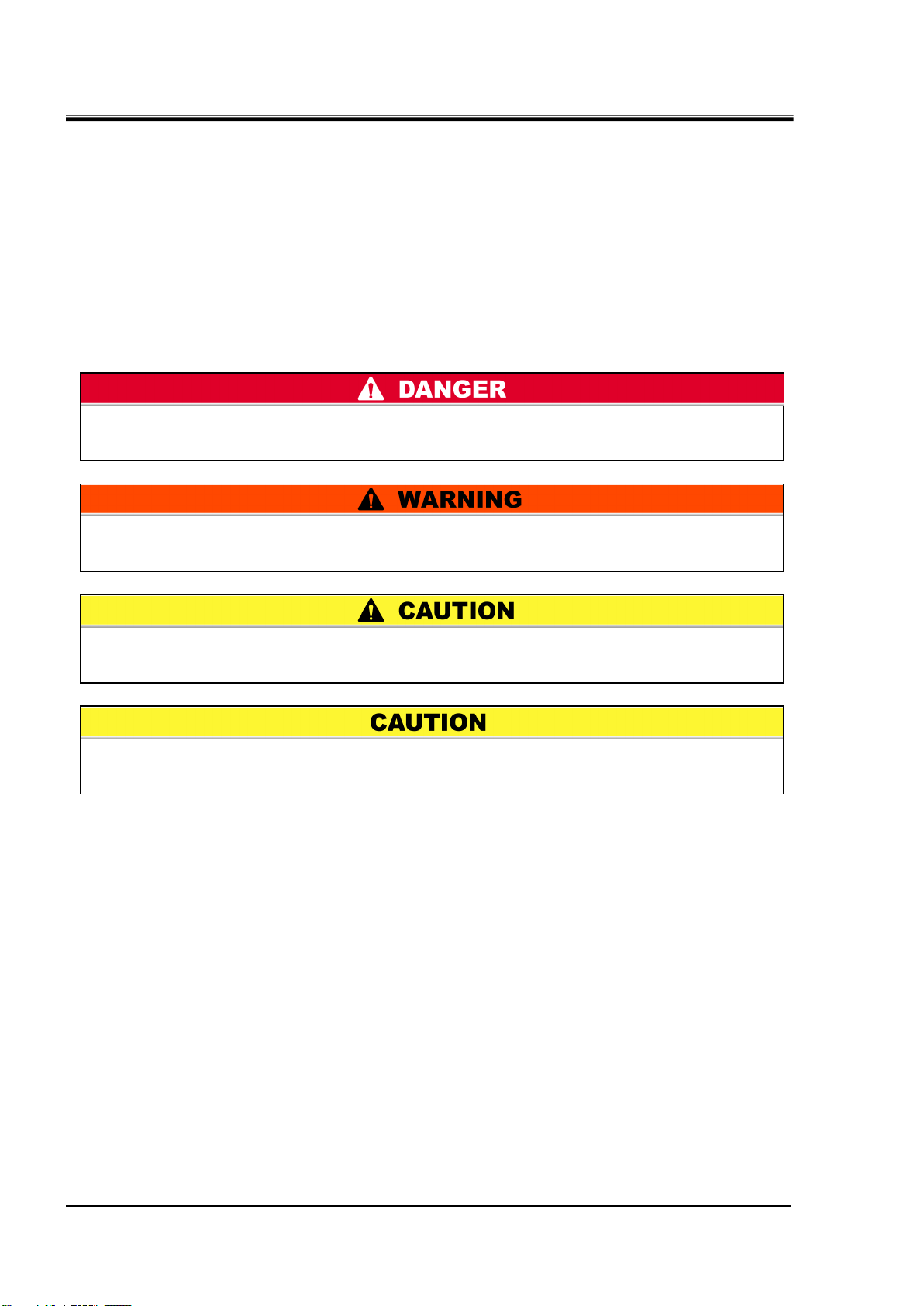
“WARNING”: Hazard that MAY cause serious personal injury or death during
operation.
“DANGER”: Hazard that WILL cause serious personal injury or death during
operation.
“CAUTION”: Hazard that MAY cause minor personal injury.
“CAUTION without exclamation symbol”: Hazard that MAY cause damage or failure
of the product, facility, devices, etc.
Chapter 1 Safety Instructions
1.3 Hazards
1.3.1 Level of hazards
The instructions given in this manual aim to assure the safe and correct
operation of the product, and to prevent injury of operators or damage to the
product. These instructions are grouped into three categories, Danger,
Warning and Caution, which indicate the level of hazard, damage and also
the degree of emergency. All safety critical information should be carefully
observed at all times.
“DANGER”, “WARNING” and “CAUTION” signs are in order according to
severity (DANGER> WARNING> CAUTION).
1.3.2 Definition of “Serious injury” and “Minor injury”
“Serious injury”
This term describes injuries that result in after effects including loss of
eyesight, burns, electric shock, fracture, poisoning, etc. and requires
long-term treatment or hospitalization.
“Minor injury”
This term describes injuries that do not need long-term treatment or
hospitalization. (Others excluded from “Serious injury”.)
1.3 Hazards
HRL Series
Page 9
1-3
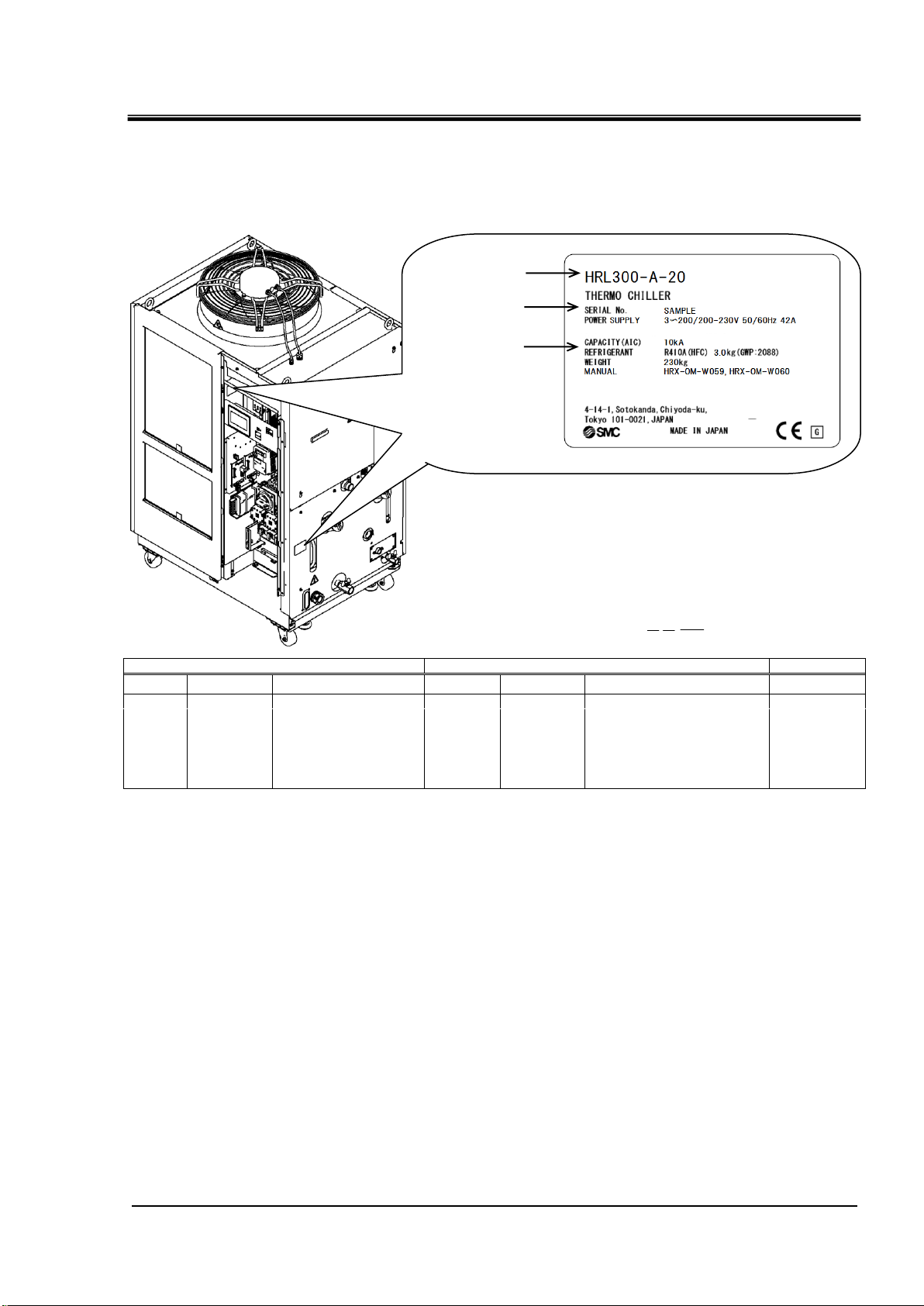
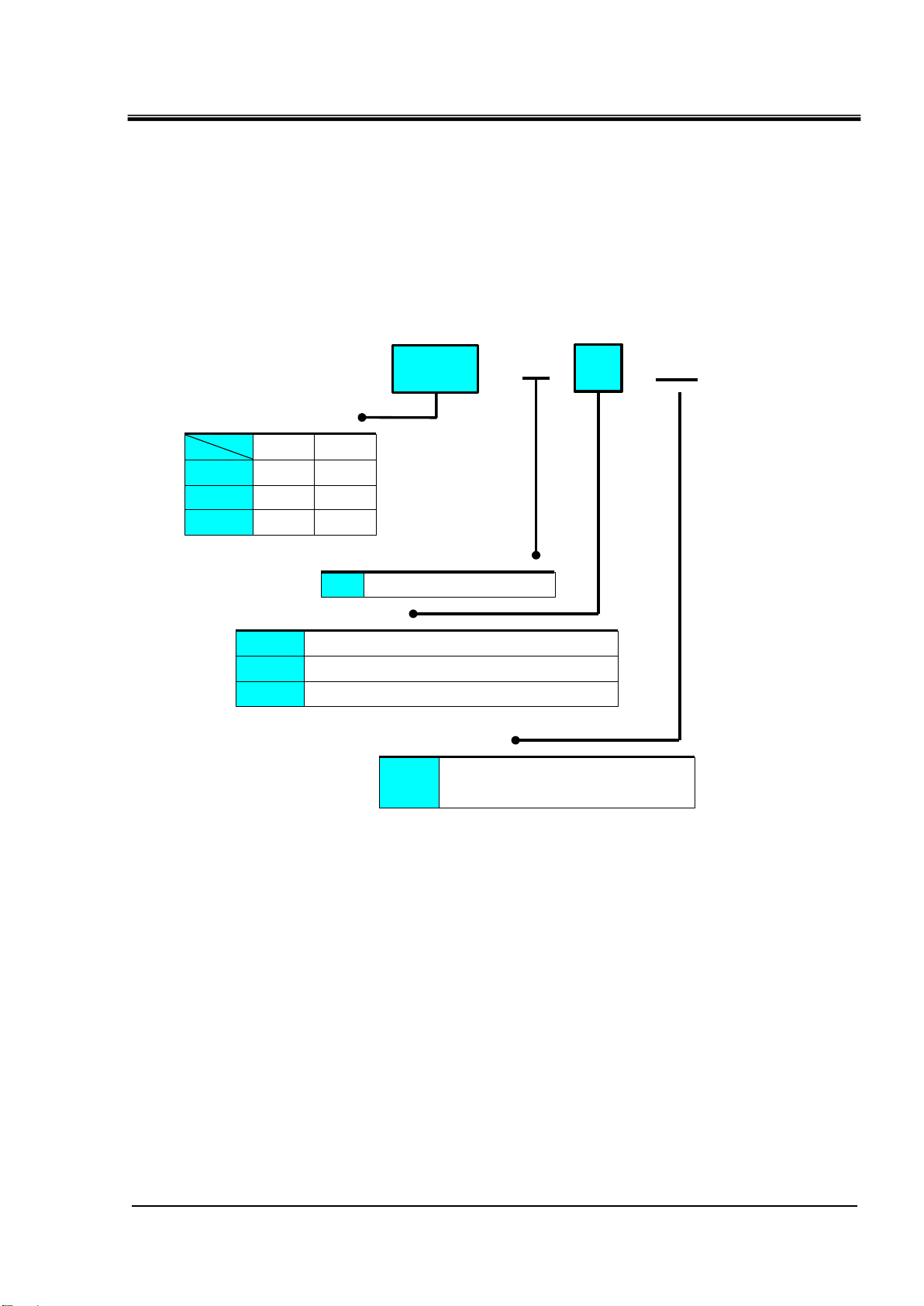
1.4 Product Label
X
R
001
Year
Symbol
Remarks
Month
Symbol
Remarks
Serial no.
2019
X
Repeated from
A to Z in
alphabetical
order
1
O
Repeated from
O to Z in alphabetical
order, with O for
January and Z for
December
-
2020 y 2 P 2021 Z 3
Q
↓ ↓ ↓
↓
* (An example of "HRL200-A-20" model.)
"3~" stands for "3 inter phase".
(IEC 60417-5032-1)
Model number
Serial number
Kind and amount
of refrigerant
Information about the product, such as Serial No. and Model No. can be
found on the product label. This information is needed when contacting an
SMC sales distributor.
HRX-OM-W060
Chapter 1 Safety Instructions
How to see the serial number X R 001 (April 2019)
Fig. 1-1 Position of the product label
HRL Series 1.4 Product Label
Page 10

HRX-OM-W060
1-4
Follow the instructions below when using the product. Failure to
follow the instructions may cause an accident and injury.
Always use safety shoes, gloves and head protection when
transporting, installing or uninstalling the product.
Always use safety shoes, gloves, mask, apron and eye protection
when handling the circulating fluid.
Always use safety shoes and gloves when operating the product.
Chapter 1 Safety Instructions
1.5 Safety Measures
1.5.1 Safety instructions for use
Read and understand this manual carefully before using the product.
Before starting maintenance of the product, be sure to lock out and tag out
the breaker of the user's power supply.
If operating the product during maintenance, be sure to inform all workers
nearby.
Use only the correct tools and procedure when installing or maintaining the
product.
Use personal protective equipment where specified (“1.5.2 Personal
protective equipment”).
Check all parts and screws are fitted correctly and securely after
maintenance.
Avoid working in a drunken or sick condition, which might cause an
accident.
Do not remove the panels except for the cases permitted in this manual.
Do not remove the panels during operation.
Do not handle this product by any means other than specified in this
Operation Manual; this can result in damage to the product or fire.
1.5.2 Personal protective equipment
This manual specifies personal protective equipment for each work.
Transport, Installing and Uninstalling
Handling of circulating fluid
Operation
1.5 Safety Measures
HRL Series
Page 11
1-5
1.6 Emergency Measures
Even when the power supply swtich is turned off, some of the internal
circuits are still energized, unless the user’s power supply is shut off.
Be sure to shut off the breaker of the user’s power supply.
Only maintenance personnel or qualified people are allowed to open
the cover panels of the product.
Do not mix the compressor oil with domestic waste for disposal. Also,
the disposal of the waste must only be conducted by specific
facilities that are permitted for that purpose.
Comply with the laws and regulations in each country for the disposal
of refrigerant and compressor oil.
The release of refrigerant in to the atmosphere is banned by law.
Recover it with specific equipment and dispose of it correctly.
Only people who have sufficient knowledge and experience about the
product and its accessories are allowed to recover the refrigerant and
compressor oil.
When emergency conditions such as natural disaster, fire, earthquake and
injury occur, shut off the breaker of the user’s power supply that supplies
power to the product.
1.7 Waste Disposal
1.7.1 Disposal of refrigerant and compressor oil
The product uses hydro fluorocarbon type refrigerant (HFC) and compressor
oil. Comply with the laws and regulations in each country for the disposal of
refrigerant and compressor oil. The type and quantity of refrigerant is
described on the “1.4 Product Label”.
HRX-OM-W060
Chapter 1 Safety Instructions
If these fluids need to be recovered, read and understand the instructions
below carefully. If there is any unclear point, contact an SMC's sales
distributor.
1.7.2 Disposal of product
The disposal of the product must be handled by a specialized industrial waste
disposal agency in accordance with local laws and regulations.
HRL Series 1.6 Emergency Measures
Page 12

HRX-OM-W060
1-6
Chapter 1 Safety Instructions
1.8 Safety Data Sheet(SDS)
If the safety data sheets of chemicals used in this product are needed,
contact an SMC's sales distributor.
Any chemicals used by the user must be accompanied by an SDS.
1.8 Safety Data Sheet(SDS
)
HRL Series
Page 13
HRX-OM-W060
2-1
HRL
④Power supply
- -
A
20
20
AC200V/200-230V(50/60Hz)
3phase
①Cooling capacity
CH1
200 19 kw
100 9 kw
③Piping thread type
Nil Rc
F G (Rc-G thread adapter set is included)
N NPT (Rc-NPT thread adapter set is included)
②Cooling method
A Air-cooled refrigeration
300 26 kw
CH2
1 kw
1 kw
1 kw
Chapter 2 Name and Function of Parts
Chapter 2 Name and Function of Parts
2.1 Model Number of Product
The product can be ordered with the model number configured as shown
below.
The product needs to be handled in different ways depending on the part
number. Refer to “1.4 Product Label" and check the part number of the
product.
HRL Series 2.1 Model Number of Product
Fig. 2-1 Product model number
Page 14
HRX-OM-W060
2-2
Chapter 2 Name and Function of Parts
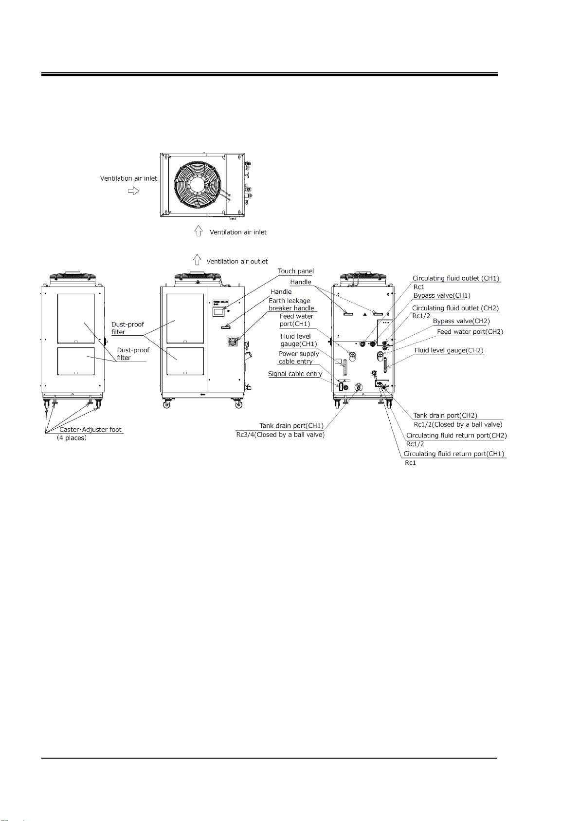
2.2 Name and Function of Parts
2.2.1 HRL-A-20 (Air cooled type)
Fig. 2-2 Names of the parts (This drawing shows “HRL200-A-20”.)
2.2 Name and Function of Parts
HRL Series
Page 15

2-3
Table 2.2-1 Accessory list
(1)
Operation Manual
2 pcs.
(English 1 pc. /Japanese 1 pc.)
(2)
Particle filter set (for CH1) 1
1 set
(3)
Particle filter set (for CH2) 1
1 set
(4)
For HRL-AF-
G thread adapter set
1 set
(For drain port)
For HRL-AN-
NPT thread adapter set
1 set
(5)
Anchor brackets 2
2 pcs.
HRX-OM-W060
Chapter 2 Name and Function of Parts
1 When “ F ” or “ N ” piping thread type is selected, the particle filter connection is “ G thread ” or “ NPT thread ”.
2 The anchor brackets are used for fixation with the skid when this product is packed. The anchor bolts are not
attached. The bolts (M8) used for fixing to the skid are not anchor bolts. Refer to "3.3.1 Installation" when using
anchor bolt fixing bracket.
HRL Series 2.2 Name and Function of Parts
Page 16

HRX-OM-W060
2-4
Name
Function
Touch panel
Runs and stops the product and performs settings such as the
circulating fluid temperature.
Fluid level gauge
Indicates the circulating fluid level of the tank. Confirm the level is
between HIGH and LOW. For details, refer to “3.5 Circulating Fluid Supply”.
Product label
Shows the product information such as model number and serial
number.For details, refer to ‘’1.4 Product Label’.
Circulating fluid
outlet port (CH1)
The circulating fluid flows out from the outlet port.
For Laser source.
Circulating fluid
outlet port (CH2)
The circulating fluid flows out from the outlet port.
For optical systems.
Circulating fluid
return port (CH1)
The circulating fluid returns to the return port.
Circulating fluid
return port (CH2)
The circulating fluid returns to the return port.
Tank drain port (CH1)
This drain port to drain the circulating fluid out of the tank.
Tank drain port (CH2)
Dust-proof filter
Inserted to prevent that the dust and contamination are clung
on the air cooled condensers directly. Clean the filter
periodically. For details, refer to “7.2.2 Monthly check”.
Power cable entry
Insert the power cable to the power cable entry and connect it
to the power terminal. For details, refer to “3.3.2 Electrical wiring”
and “3.3.3 Preparation and wiring of power supply cable”.
Power terminal
Signal cable entry
Insert the signal cable to the signal cable entry and connect it to
the signal connectors. For details, refer to “3.3.5 Wiring of Run/Stop signal
input”, “3.3.6 Wiring of contact output signal”, “3.3.7 Wiring of analog output
signal”,“3.3.8 RS-485 communication wiring”,
“3.3.9 RS-232C communication wiring” or the Operation
Manual Communication Function.
Signal connecors
Earth leakage breaker
/ Breaker handle
Shuts off the power supply to the internal equipment of the product.
(Parts energized remained in the product.)
Refer to “3.3.2 Electrical wiring” for the earth leakage breaker.
Water fill port
Supply circulating fluid to the tank.
Chapter 2 Name and Function of Parts
2.3 Function of Parts
The function of parts is as follows.
Table 2.3-1 Function of parts
2.3 Function of Parts
HRL Series
Page 17

Chapter 3 Transport and Setting Up
3-1
Only persons who have sufficient knowledge and experience about
the product and system are allowed to transport and set up the
product.
Especially pay attention to personal safety.
Drain the residual fluid from the piping as much as possible to prevent
any spillage.
Never lay the product on its side.
The compressor oil will leak in to the refrigerant piping, which may
cause early failure of the compressor.
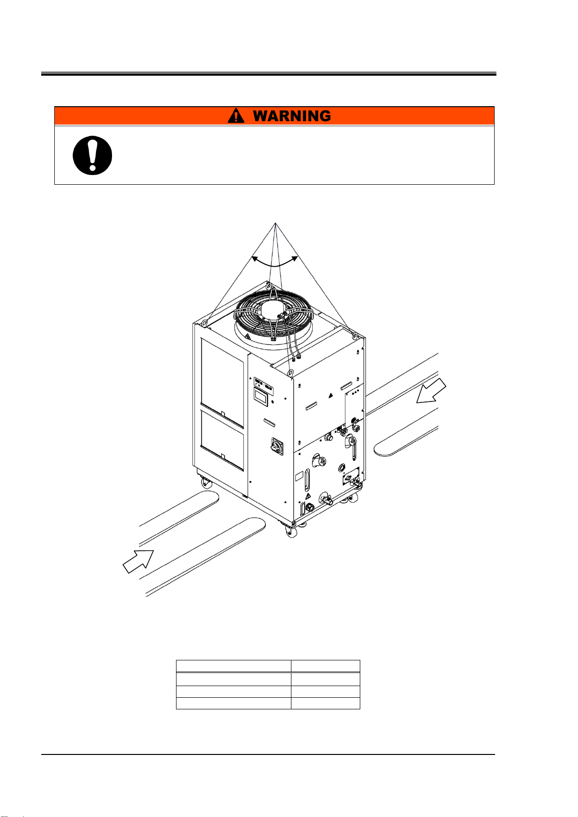
When the product is carried by using a forklift, make sure that the
fork does not damage the cover panel or piping port.
Be sure to use all the four eye bolts when slinging the product.
The slant angle of each rope should be 60 degrees or less.
When moving the product by a forklift, insert the fork into the right
positions referring to 3.1.1 Transportation using forklift and hangingMoving by forklift and slinging should be done by persons who have
the licenses.
Chapter 3 Transport and Setting Up
3.1 Transport
The product is heavy and has potential danger at transport. Also, to prevent
damage and breakage of the product, be sure to follow the instructions
shown below for transport.
HRX-OM-W060
HRL Series 3.1 Transport
Page 18
HRX-OM-W060
3-2
Model
Weight kg
HRL100-A-20
Approx.222
HRL200-A-20
Approx.251
HRL300-A-20
Approx.315
Fork inserting position
Position to hang
60°or less
Fork inserting position
This is a heavy product. (Refer to Table 3.1-1 Weight of the product)
Moving by forklift and slinging should be done by persons who have
the licenses.
Chapter 3 Transport and Setting Up
3.1.1 Transportation using forklift and hanging
Fig. 3-1 Fork inserting and hanging position (This drawing shows “HRL200-A-20”.)
Table 3.1-1 Weight of the product
3.1 Transport
HRL Series
Page 19
HRX-OM-W060
3-3
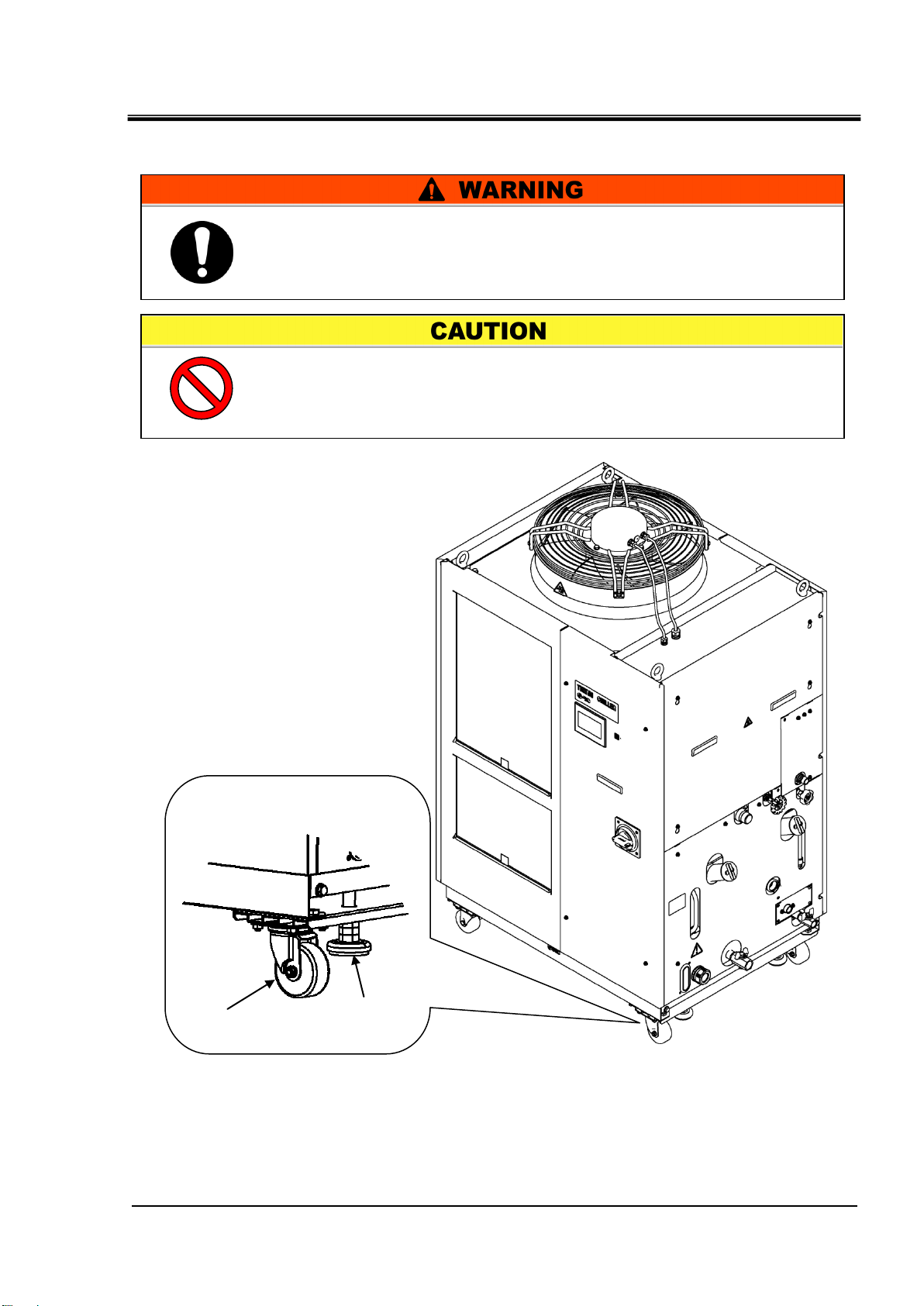
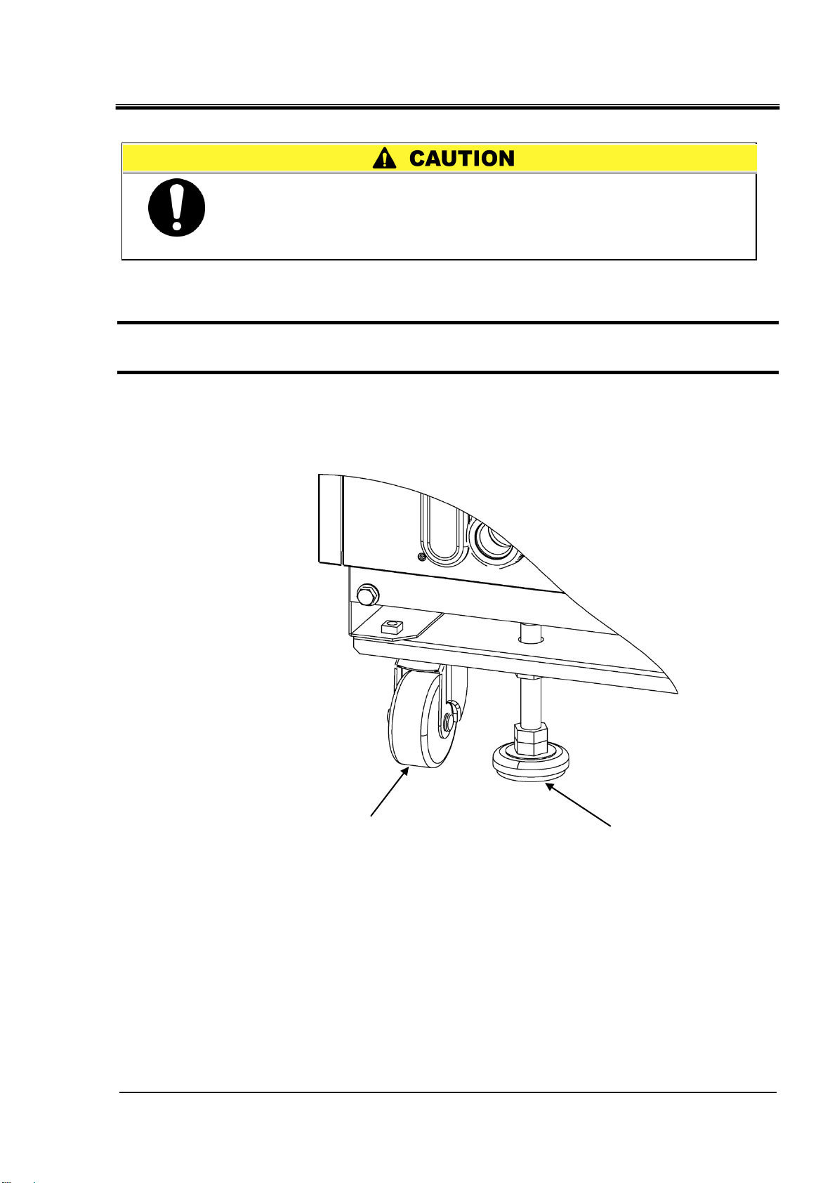
Raise the adjuster
foot.
Swivel
caster
Each swivel caster can
rotate 360 degrees freely.
Raise the adjuster feet and push the corners of the product when
moving the product using the casters.
Do not hold the piping connections or handles of the panels when
moving by casters, or it may cause damage to the product..
This is a heavy product. (Refer to Table 3.1-1 Weight of the product).
Moving the product by casters should be done by 2 persons or more.
Chapter 3 Transport and Setting Up
3.1.2 Transportation using casters
Fig. 3-2 Transportation using casters
HRL Series 3.1 Transport
Page 20
HRX-OM-W060
3-4
Do not set up the product in places possibly exposed to leakage of
flammable gas. Should any flammable gas stay around the product,
the product may cause a fire.
Keep the product upright on a rigid and flat floor which can resist the
weight of the product, and take measures to prevent the product from
tipping over. Improper installation may cause water leakage, tipping,
damage of the product or injure the operator.
Keep the ambient temperature of the product between 2 to 45oC.
Operation out of this ambient temperature range may cause a
malfunction of the product. Operating the product in an environment
temperature of 45 oC may reduce the heat discharging efficiency of
the heat exchanger and the safety device may function, resulting in
the product operation stoppage.
The installer/end user is responsible for carrying
out an acoustic noise risk assessment on the equipment after
installation and taking appropriate measures as required.
Chapter 3 Transport and Setting Up
3.2 Installation
3.2.1 Environment
The product must not be operated, installed, stored or transported in the
following conditions. Potential malfunction or damage to the product may
occur if these instructions are disregarded.
This product is not designed for clean room usage. The pump and ventilating
fan inside the product generate particles.
● Location that is outside.
● Location that is exposed to steam, salt water or oil.
● Location that is exposed to dust or powder material.
● Location that is exposed to corrosive gas, organic solvent, chemical solution, or
flammable gas. (The product is not explosion-proof.)
● Location where the ambient temperature is out of the following range:
During transportation or storage: -15 to 50°C (No water or circulating fluid in the
piping.)
During operation : 2 to 45°C
● Location where condensation forms on the inside electrical parts.
● Location that is exposed to direct sunlight or heat radiation
● Location that is near heat sources and poor in ventilation.
● Location that is subjected to abrupt changes in temperature.
● Location that is subjected to strong electromagnetic noise (intense electric field,
intense magnetic field, or surges).
● Location that is subjected to static electricity, or conditions where static electricity can
discharge to the product.
● Location that is subjected to strong high frequencies raditation.
3.2 Installation
● Location that is subjected to potential lightening srtike.
● Location at altitude of 3000m or higher (except during product storage and transport).
Refer to below for details.
● Location where the product is affected by strong vibrations or impacts.
● Condition that applies external force or weight causing the product to be damaged.
● Location without adequate space for maintenance as required.
HRL Series
Page 21
Chapter 3 Transport and Setting Up
3-5
Altitude [m]
1. Max. ambient
temp. [oC]
2. Cooling capacity
correction coefficient
Less than 1000m
45
1.00
1000 m or more - Less than 1500 m
42
0.85
1500m or more - Less than 2000m
38
0.80
2000m or more - Less than 2500m
35
0.75
2500m or more - Less than 3000m
32
0.70
Thermo-chiller installation in high altitude of 1000 meters or more
Because of lower air density, the heat radiation efficiencies of the devices in
the product will be lower in the location at altitude of 1000m or higher. For this
reason, the maximum ambient temperature for the thermo-chiller operation
and the cooling capacity will be reduced.
For product installation at a place of high altitude of 1000 meters or more,
select a thermo-chiller of the applicable capacity referring to the table below.
1. Max. ambient temp.: Use the product in lower ambient temperature
than the described value at each altitude.
2. Cooling capacity correction coefficient: Coefficient to calculate the cooling
capacity at each altitude
For the product operation at an altitude of 1800 meters, the cooling capacity
at an altitude of 1800 meters = “8.4 Cooling Capacity” x 0.8.
HRX-OM-W060
HRL Series 3.2 Installation
Page 22

HRX-OM-W060
3-6
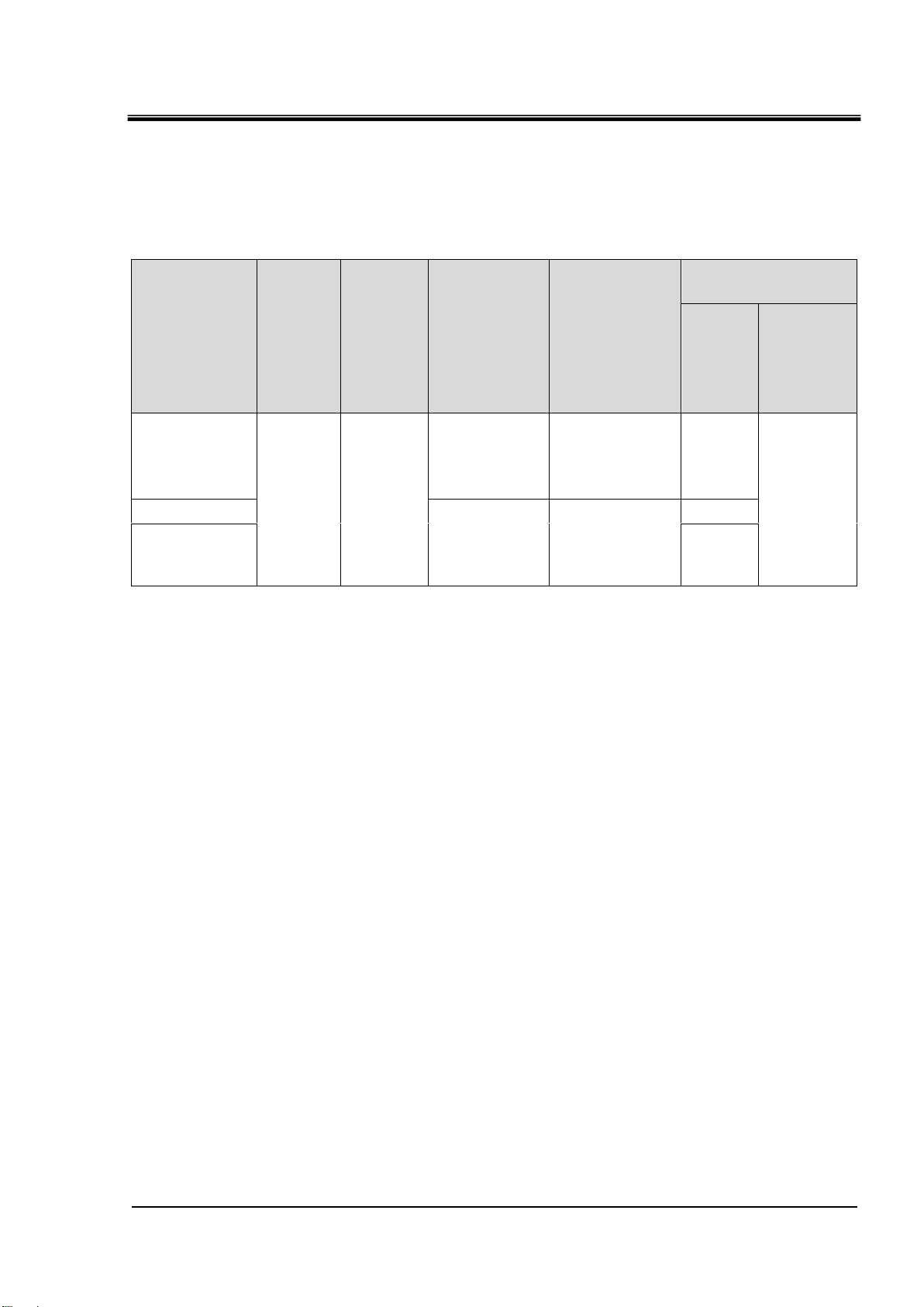
Model
Heat
radiation
(kW)
Required ventilation amount (m3/min)
Differential temp. of
3 oC between inside and
outside of installation
area
Differential temp. of
6 oC between inside and
outside of installation
area
HRL100-A-20
Approx.18
305
155
HRL200-A-20
Approx.35
590
295
HRL300-A-20
Approx.45
760
380
Do not install in a location which can be subjected to any of the
conditions in “3.2.1 Environment”.
Radiates heat from the air vent of the cooling fan.
If the product is operated with insufficient air ventilation the internal
temperature can exceed 45oC, which can cause and affect the
performance and life of the product. To prevent this ensure that
suitable ventilation is available (see below).
Chapter 3 Transport and Setting Up
3.2.2 Location
nstallation of multiple products
Keep sufficient space between products so that the air vented from one product will not be taken in
Installation at indoor site
by other products.
1. For a facility having a large installation area (that can vent the air naturally):
Make an air outlet on a wall at a high level and air inlet on a wall at a low level, to allow for
adequate airflow.
2. For a facility having a small installation area (that can not vent the air naturally):
Make a forced air exhaust vent on a wall at a high level and an air inlet on a wall at a low level.
3. Using duct to exhaust the air:
In case the indoor site cannot accept the exhausted air from the product or/and is air
conditioned, ventilate by installing a duct on the outlet ventilation of the product. Do not fasten
the duct on the outlet ventilation of the product directly. Have the space at least the duct’s
diameter apart. Use a fan for the duct that considered the ventilation resistance of the duct.
Table 3.2-1 Amount of radiation and required ventilation
Installation environment specifications
Sound noise:HRL100-A-20 : 75 dB(A)
HRL200-A-20 : 75 dB(A)
HRL300-A-20 : 71 dB(A)
* Front 1m, height 1m, rated condition
3.2 Installation
HRL Series
Page 23

3-7
3.2.3 Installation and maintenance space
800mm or more
800mm or more
2000mm or more
400mm or more
800mm or more
Have an enough space for the ventilation for the product. Otherwise it
may cause a lack of cooling capacity or/and stoppage of the product.
Ensure there is enough space for maintenance.
It is recommended to keep the space around the product shown in Fig. 3-3.
Fig. 3-3 Installation space (This drawing shows “HRL-A-20”.)
HRX-OM-W060
Chapter 3 Transport and Setting Up
HRL Series 3.2 Installation
Page 24
HRX-OM-W060
3-8
Anchor bolt
Nut
Base of the product
Hole for anchor bolt (12mm)
Bracket
Install the product on a vibration free level floor.
Prepare the M10 anchor bolts that are suitable for the material of the
floor that the product will be installed on. Drive the anchor bolts in at
least two places on the left and right sides of the product (four places
in total). Refer to “8.2 Dimensions” for the dimensions for the position
of the anchor bolts.
Chapter 3 Transport and Setting Up
3.3 Installation
3.3.1 Installation
Use a bracket
1. Install this product according to the anchor bolts installed on the level floor.
2. Fasten the nuts to the anchor bolts.
3. Make sure that there is no looseness on all the anchor bolts and nuts.
[Tips]
SMC Foundations bolt set “IDF-AB500” (SUS M10x50mm) is applicable.
Please order separately.
3.3 Installation
Fig. 3-4 Installation procedures
HRL Series
Page 25
3-9
Use the adjuster foot
Lower the adjuster to the level floor
to fix the product in place.
Caster
Install the product on a vibration free level floor.
be sure to use the adjuster foot to install on the floor. The adjuster foot
is not earthquake-proof. If necessary make an earthquake-resistant
measure on the customer side.
1. Install the product on a level floor.
2. Lower the adjuster to the level floor to fix the product in place.
Fig. 3-5 Installation by adjuster foot
HRX-OM-W060
Chapter 3 Transport and Setting Up
HRL Series 3.3 Installation
Page 26
HRX-OM-W060
3-10
Do not modify the internal electrical wiring of the product. Incorrect
wiring may cause electric shock or fire. Also, modifying the internal
wiring will void the product’s warranty.
NEVER connect the ground to water line, gas pipe or lightning
conductor.
The installation of electrical equipment and wiring work should be
performed only by personnel with sufficient knowledge and
experience.
Be sure to shut off the user’s power supply. Wiring with the product
energized is strictly prohibited.
The wiring must be conducted using cables complying with “Table
3.3-1” and firmly secured to the product to prevent the external force
of cables being applied to the terminals. Incomplete wiring, or
improper securing of wiring, may cause electrical shock or excessive
heat and fire.
Ensure a stable power supply with no voltage surges.
Ensure that an earth leakage breaker is used in the power supply of
the product. See “Table 3.3-1”.
Use a power supply suitable for the specifications of the product.
Use a power supply of over voltage category 3 (IEC60664-1)*.
Be sure to connect the ground connection.
Ensure that a lock out facility is availble on the power supply.
Each product must have its own separate earth leakage breaker.
Otherwise there can be a risk of electric shock or fire.
Ensure that no harmonics are superimposed at power supply.
(Do not use inverter, etc.)
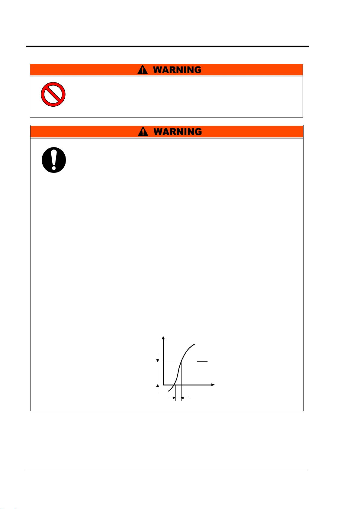
Supply a steady power supply which is not affected by surges or
distortion. In particular, if the voltage rate of increase (dv/dt) at
zero crossing exceeds 40V/200μsec, it may cause malfunction.
V
dV
dt
dt
= Voltage ratio
on zero-cross point
dV
t
Voltage rise %
Time
Voltage
Chapter 3 Transport and Setting Up
3.3.2 Electrical wiring
3.3 Installation
HRL Series
Page 27
HRX-OM-W060
3-11
Model
Power
supply
voltage
Terminal
block
screw
diameter
Recommend
ed crimp
terminal
Cable
Specifications
1
Earth leakage
breaker
Breaker
size
(A)
Sensitivity
of
leakage
current
(mA)
HRL100-A-20
200 VAC/
200-230
VAC
50/60Hz
3 phase
M5
R5.5-5
4 cores x
AWG10
(4 cores x 5.5 mm2)
*including
ground
30
30
HRL200-A-20
R8-5
4 cores x
AWG8
(4 cores x 8 mm2)
*including
ground
40
HRL300-A-20
50
Chapter 3 Transport and Setting Up
Power supply specifications, power supply cable and earth leakage breaker
Prepare the power supply shown in the following table. For the connection between the
product and power supply, use the power supply cable and earth leakage breaker shown
below. An earth leakage breaker must be mounted to a position where the breaker is easily
accessible and close to the thermo-chiller.
Table 3.3-1 Power supply cable and earth leakage breaker (Recommended)
*1. Cable specifications are the examples when using the product at a continuous allowable operating
temperature of 70 oC, with an operating voltage of 600 V and two kinds of plastic insulated wires at an
ambient temperature of 30 oC. Please select the proper size cables according to the actual condition.
HRL Series 3.3 Installation
Page 28
HRX-OM-W060
3-12
The electrical facilities should be installed and wired in accordance
with local laws and regulations of each country and by a person who
has knowledge and experience.
Check the power supply. Operation with voltages, capacities and
frequencies other than the specified values can cause fire and electric
shock.
Wire with an applicable cable size and terminal. Forcibly mounting
with an unsuitably size cable may result in heat generation or fire.
Be sure to lock out and tag out the breaker of the facility power supply
(customer power supply facility) before wiring.
Be sure to connect the power supply cable from the product side first,
and then connect the breaker of the facility power supply (the user’s
machine power supply).
When the panel is removed or mounted, be sure to wear protective
shoes and gloves to prevent injury with the edge of the panel.
Chapter 3 Transport and Setting Up
3.3.3 Preparation and wiring of power supply cable
3.3 Installation
HRL Series
Page 29
3-13
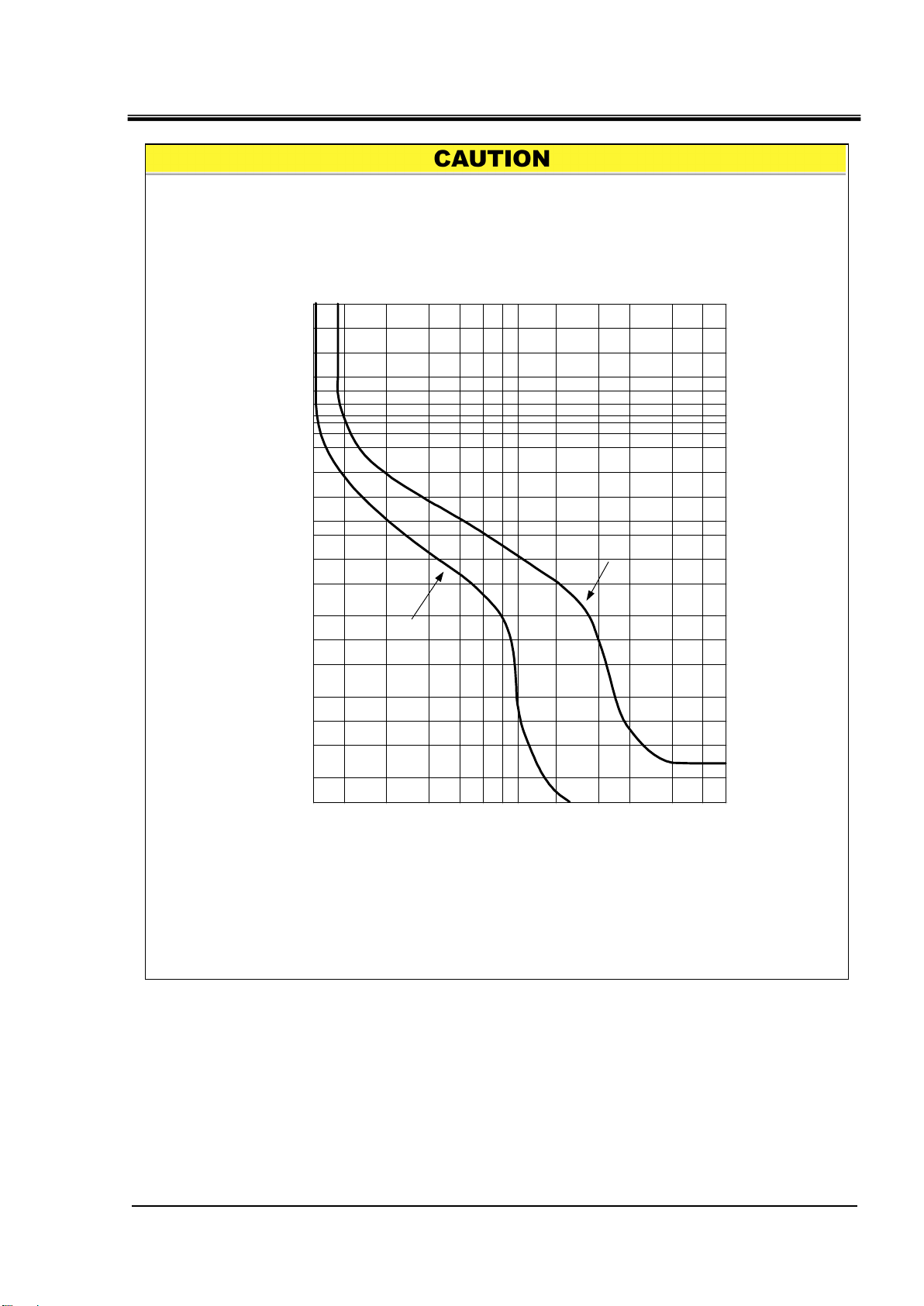
A breaker that has the operating characteristic below is installed. Please use a
breaker that has the same or longer operating time as/than this for the customer
side (upstream side). If it has a shorter operating time, there is a possibility of
accidental breaker trip due to the internal motors’ inrush currents of this product.
4h
2h
1h
30min
20min
14min
10min
6min
4min
2min
1min
30s
20s
10s
5s
2s
1s
0.5s
0.2s
0.1s
0.05s
0.02s
0.01s
100 135 200 300 400 500600700 1000 1500 2000 3000 4000
Current (% for breaker capacity)
Operating time
Min.
Max.
HRX-OM-W060
Chapter 3 Transport and Setting Up
Operating characteristics of the breaker
HRL Series 3.3 Installation
Page 30
HRX-OM-W060
3-14
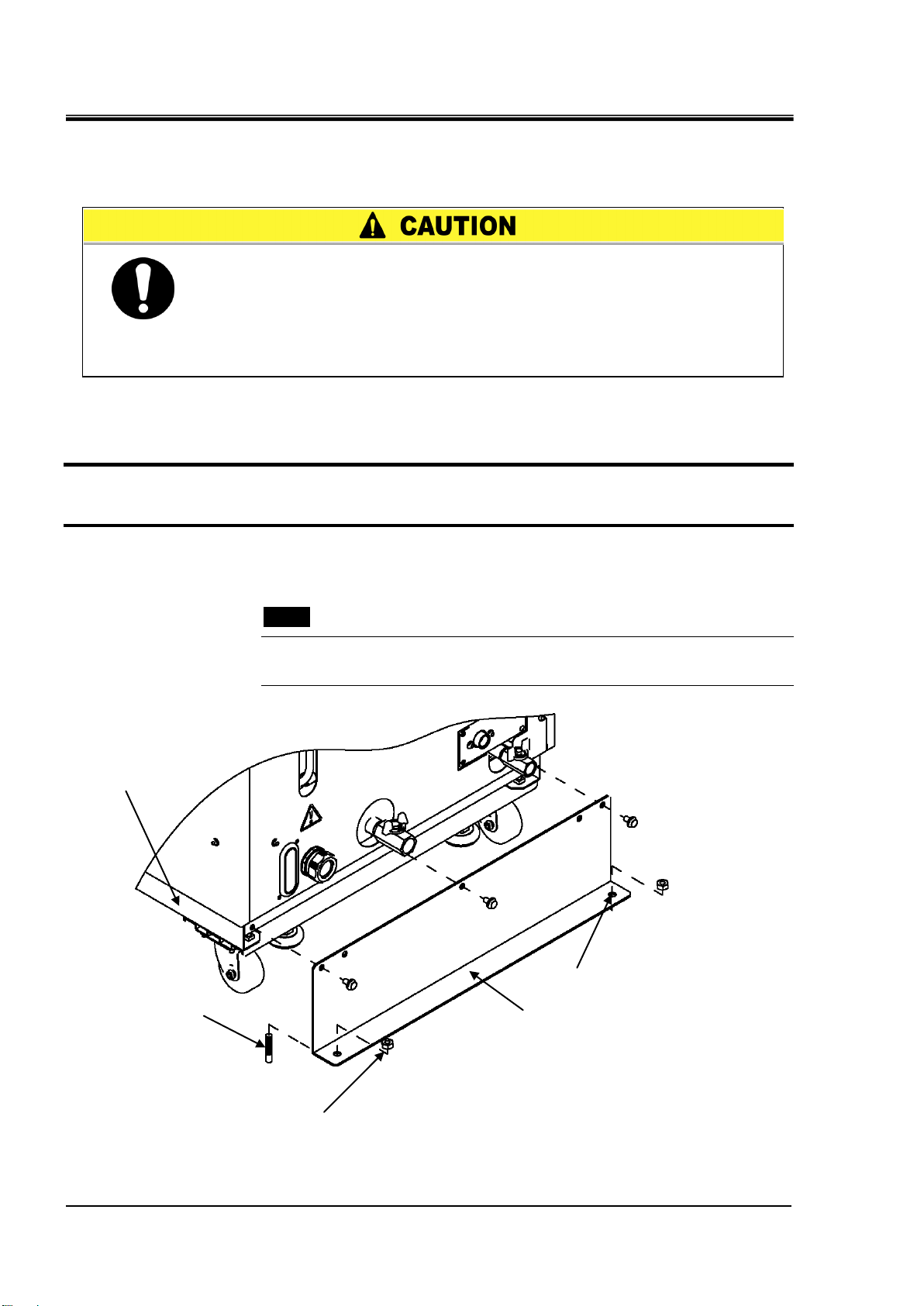
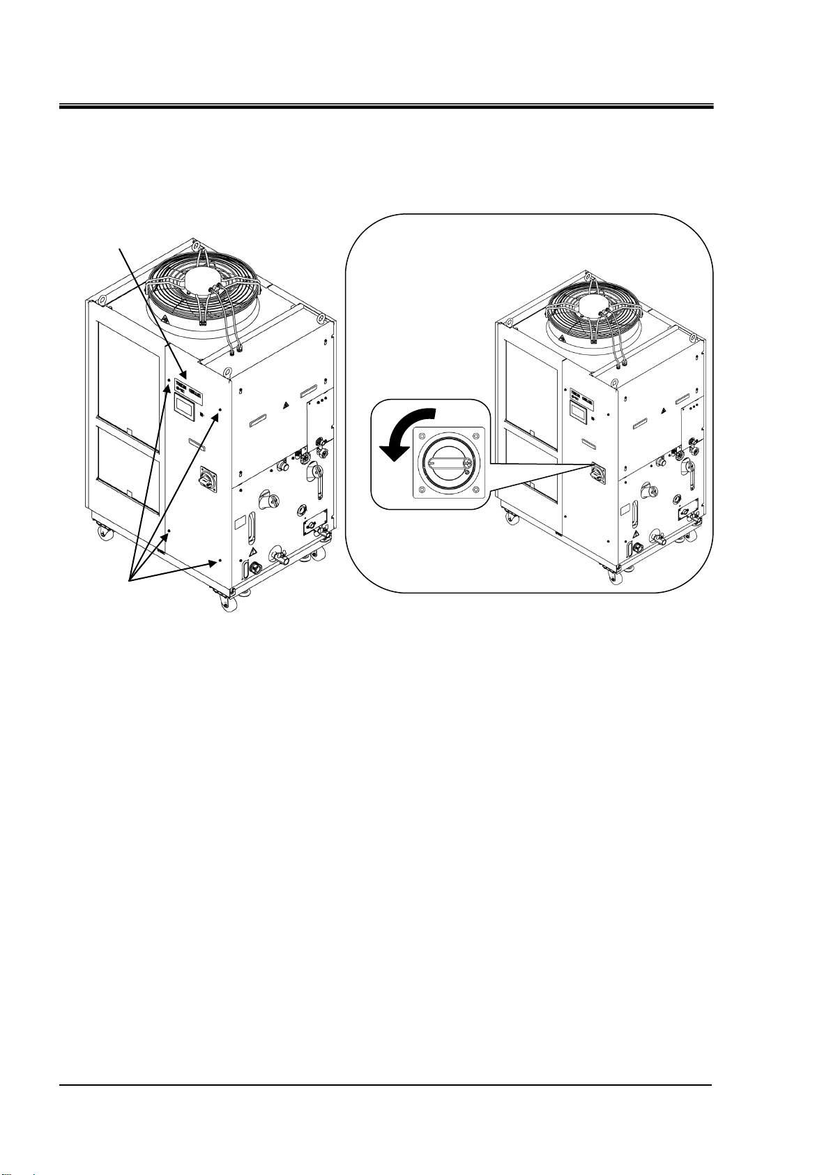
OFF
Note: Turn off the earth leakage breaker.
The front panel of the electrical unit
cannot be removed without turning off
the breaker.
Screw
Front panel for the
electrical unit
Chapter 3 Transport and Setting Up
Preparation for operation
1. Remove four screws to remove the front panel for the electrical unit.
Fig. 3-6 Remove the front panel for the electrical unit
3.3 Installation
HRL Series
Page 31

Chapter 3 Transport and Setting Up
3-15
Handle
View A
power supply cable
Cap
2. Hold the handle and pull up the front panel of the electrical unit, and remove it.
Fig. 3-7 Remove the front panel for the electrical unit
HRX-OM-W060
3. Loosen the power cable outlet cap and insert the power cable.
Fig. 3-8 Wiring of power supply cable
HRL Series 3.3 Installation
Page 32

HRX-OM-W060
3-16
power supply cable
PE L1 L2 L3
View A
Chapter 3 Transport and Setting Up
4. Connect the power supply cable and the ground cable as shown in the figure below.
Fig. 3-9 Wiring of power supply cable
* Connect an over current protection to the power cable connected to the equipment to avoid hazard.
3.3 Installation
HRL Series
Page 33

Chapter 3 Transport and Setting Up
3-17
Connector specification (this product side)
Dsub 25 pin female (socket) type
Be sure to lock out and tag out the breaker of the facility power supply
(the user’s machine power supply) before wiring.
Use the connector that are specified.
The capacity of the output contact of the product is limited. If the capacity is
not large enough, install a relay, etc. (to allow for larger capacity). Also, ensure
that the input current of the relay is small enough in relation to the contact
capacity of the product.
3.3.4 Contact input/output communicatin wiring
The product has a contact input/output communication function as shown
below. Connect cables referring to the applicable chapter for each function.
Run/Stop input (Refer to “3.3.5 Wiring of Run/Stop signal input”)
HRX-OM-W060
Contact output signal(Refer to “3.3.6 Wiring of contact output
signal”)
Analog output signal (Refer to “3.3.7 Wiring of analog output signal”)
Use the signal cable described below for wiring of each function.
Contact Input/Output communication connector
The following connectors are used for this product as a contact input / output
signal connector. Please prepare suitable mating connector cable.
Table 3.3-2 Contact input/output communication connector
HRL Series 3.3 Installation
Page 34

HRX-OM-W060
3-18
Item
Specification
Contact
input
signal1,2,3
Insulation system
Photo coupler
・Run/Stop signal
・External switch signal
・Operation mode request signal
(Contact input 3 fixed)
Rated input
voltage
DC24V
Operating voltage
range
DC21.6V to 26.4V
Rated input
current
5mA TYP
Input impedance
4.7kΩ
Contact output
signal
1,2,3,4,5,6
Rated load
voltage
AC48V or less /
DC30V or less
・Signal of operating status
・Alarm signal
・TEMP READY signal etc *2
Maximum load
current
AC/DC 800mA or less *1
Minimum load
current
DC5V 10mA
Analog output
signal 1,2
Output voltage range
0V to +10V
 ̄
Maximum output current
10mA
Maximum accuracy
±1.0%F.S. or less
DC24V output voltage
DC24V±10% 200mA MAX 1
(It can not be used for inductive load.)
Chapter 3 Transport and Setting Up
Table 3.3-3 Contact input/output/ analog output communication specification
1:The total load current must be 800 mA or less. To use the power of the device, the total load current
must be 200 mA or less.
2:Refer to “3.3.6 Wiring of contact output signal”
3.3 Installation
HRL Series
Page 35

HRX-OM-W060
3-19
PIN
No.
Application
Division
Default setting
1
DC24V output
Output
-
2
DC24V input
Input
-
3
Contact input signal 1
Input
Run/Stop 1
4
Contact input signal 3
Input
Operation mode request signal (fix )2
5
Contact output signal 6
Output
OFF1
6
Contact output signal 1
Output
Run status signal [N.O type](fix)2
7
Contact output signal 3
Output
Operation continuation[WRN]alarm signal
[N.C. type ](fix)2
8
Contact output signal 5
Output
OFF 1
9
None
-
-
10
Analog output signal 2
Output
CH2 Electric conductivity 1
11
Analog output signal 1
Output
CH2 Circulating fluid temperature 1
12
None
-
-
13
None
-
-
14
24 COM output
(Common of contact input signal)
Output
-
15
Common of contact output signal
1, 2, 3, 4, 5
Output
-
16
Contact input signal 2
Input
External switch signal 1
17
None
-
-
18
Common of contact output signal 6
Output
-
19
Contact output signal 2
Output
Operation stop [FLT] alarm signal
[N.C. type ](fix)2
20
Contact output signal 4
Output
OFF 1
21
None
-
-
22
Common of contact output signal 2
Output
-
23
Common of contact output signal 1
Output
-
24
None
-
-
25
None
-
-
Chapter 3 Transport and Setting Up
Table 3.3-4 Contact input/output communicatin /Analog output pin number
1 : It is possible to change the setting.
2 : You can not change the setting(“N.O type / N.C. type” can be changed).
HRL Series 3.3 Installation
Page 36

HRX-OM-W060
3-20
Fig. 3-10 Circuit diagram
When using this product's power supply,
connect pin 1 to pin 2 and the COM side
of each contact input signal to pin 14.
When using a customer's power
supply, connect the 24V DC +
side to pin 2 and the COM side
of each contact input signal to
the customer's power COM.
Power supply usage example
Customer power supply usage example
DC24V
1
14
3
2
1
14
3
2
Power
supply
DC24V
24COM
4
3
4
This product power supply
usage example
Analog output 1 : CH2 Circulating fluid temperature
This product side Customer system side
DC24V
+
-
-15V
100Ω
ANALOG COM
24COM
Contact output 1 : Operation status
1
24COM
DC +24V(output)
4.7kΩ
4.7kΩ
4.7kΩ
+15V
+
-
-15V
100Ω
+15V
ANALOG COM
Internal
circuit
14
3
16
4
6
19
7
20
8
15
5
18
11
23
10
22
Contact output 2 : "FLT"
Contact output 3 : "WRN"
Contact output 4 : OFF
Contact output 5 : OFF
(Momentary)
Run/Stop
Operation mode request
[Warning alarm occurrence OFF]
[Fault alarm occurrence OFF]
[Operation ON]
Contact output 6 : OFF
2
DC24V
DC +24V(input)
EXT DC24V
EXT 24COM
Power
supply
Analog output 2 : CH2 Electric conductivity
External switch
24COM(output)
Contact output 1-5 common
Contact output 6 common
Analog output1common
Analog output 2 common
Chapter 3 Transport and Setting Up
3.3 Installation
HRL Series
Page 37

HRX-OM-W060
3-21
Chapter 3 Transport and Setting Up
3.3.5 Wiring of Run/Stop signal input
This product can be remotely controlled by the contact signal. This chapter
illustrates examples of wiring.
To enable Run / Stop signal input, set the operation mode to "DIO mode"
after wiring. (Refer to “5.4.1 Home screen Operation mode”(P.5-12)).
[Tips]
This product has three input signals. Two of them can be customized
depending on the customer’s application.
1. Prepare the switch (power supply voltage: 24 VDC, contact capacity: 35 mA or more,
minimum load current: 5mA) and suitable connector cable.
HRL Series 3.3 Installation
Page 38

HRX-OM-W060
3-22
14 〃 1
2
3
Pin No.
〃 〃 ←Run/Stop signal
Inlet of the signal
cable
Note: Prepare a cable tie.
Fasten the signal cable to
the mount on the base with
the cable tie.
Mount for
cable tie
D sub 25 female pin
(socket) type
13
1
25
14
Chapter 3 Transport and Setting Up
2. Wire the contact input / output signal connector as follows and connect it to this
product. (This wiring is an example.)
Fig. 3-11 Wiring of Run/Stop signal input and remote signal input (Example)
3.3 Installation
HRL Series
Page 39

3-23
3.3.6 Wiring of contact output signal
Contact
output
Content of the signal
(Default setting)
Operation
Contact output
signal 1
Operation status
signal
N.O.
During operation:Contact closed
During operation stop:Contact open
With power supply cutoff:Contact open
Contact output
signal 2
Operation stop
[FLT] alarm signal
N.C
While alarm being generated:Contact open
While alarm being generated:Contact
closed
With power supply shut off:Contact open
Contact output
signal 3
Operation
continuation[WRN]
alarm signal
N.C
While alarm being generated:Contact open
While alarm being generated:Contact
closed
With power supply shut off:Contact open
Contact output
signal 4,5,6
OFF
-
-
Be sure to turn OFF the breaker of the facility power supply (the user's
machine power supply) before wiring.
Contact output signals are the signals that output the status of this product.
Contact specification of each signal output is shown below.
Contact specification of each signal output is shown below.
Table 3.3-5 Contact signal output at the factory setting
HRX-OM-W060
Chapter 3 Transport and Setting Up
[Tips]
This product has six output signals. Three of them can be customized to
user’s application
Signals shown below can be output. Refer to “5.4.10 Communication setting
screen ”.
・DIO MODE signal output
・Alarm signal output
・Maintenance remainder signal output
・CH1 TEMP READY signal output
・CH2 TEMP READY signal output
・TEMP OUT signal output
・Startup setting signal output
・Anti-freezing setting signal output
・Warming up setting signal output
・Operation mode request signal status
・Selected alarm signal output
・Selected maintenance signal output
HRL Series 3.3 Installation
Page 40

HRX-OM-W060
3-24
No.
Signal item
Output voltage
Default setting
1
CH2 circulating fluid
temperature
0.0 to 100.0 °C:0.00 to 10.00V
Analog output 1
2
CH2 electric conductivity
0.1 to 50.0μS/cm:0.02 to 10.00V
Analog output 2
3
CH1 circulating fluid
temperature
0.0 to 100.0 °C:0.00 to 10.00V
-
Connector specification (this product side)
Dsub 9 pin female (socket) type
Be sure to turn OFF the breaker of the facility power supply (the user's
machine power supply) before wiring.
Chapter 3 Transport and Setting Up
3.3.7 Wiring of analog output signal
This product can output analog signals
The contents of the analog output signal and the factory settings are as follows.
The signal content can be selected from three types. Refer to “5.4.10 Communication setting
screen”
Table 3.3-6 Analog output signal
3.3.8 RS-485 communication wiring
This product can operate the following by serial communication RS-485.
-Control of Run/Stop
-Circulating fluid temperature setting
-Circulating fluid temperature reading
-Operation status reading
-Alarm condition reading
Refer to Operation Manual Communication Function for more details.
RS-485 communication connector
The following connector is used for this product as a connector for RS – 485
communication. Please prepare suitable mating connector.
Table 3.3-7 RS-485 communication connector
3.3 Installation
HRL Series
Page 41

HRX-OM-W060
3-25
Dsub 9 female pin
(socket) type
5
1
9
6
Be sure to turn OFF the breaker of the facility power supply (the
user's machine power supply) before wiring.
Chapter 3 Transport and Setting Up
Fig. 3-12 RS-485 communication wiring
Wiring of interface communication cable
Connecting to PC
RS-485 cannot be directly connected to a normal PC. Use a RS-232C/RS485 converter
which is available on the market.
HRL Series 3.3 Installation
Page 42

HRX-OM-W060
3-26
Connector specification (this product side)
Dsub 9 pin female (socket) type
2
SD+ 5 SG 7 SD-
SD+
SD-
SG
Terminal
Master
This product
(first slave)
2
SD+ 5 SG 7 SD-
This product
(second slave)
2
SD+ 5 SG 7 SD-
This product
(31 slaves)
st
resistance
resistance
Terminal
Chapter 3 Transport and Setting Up
Be sure to follow the wiring procedure shown below for connecting multiple thermo-chillers.
Configuration of connection
One thermo-chiller for one host computer, or multiple thermo-chillers for one host
computer.
(31 thermo-chillers can be connected at maximum.)
[Tips]
Both ends of the communication connection (the end nodes) need to be
connected to the host computer.
If the terminating resistor is required, please be connected by the customer.
3.3.9 RS-232C communication wiring
This product can operate the following by serial communication RS-232C.
-Control of Run/Stop
-Circulating fluid temperature setting
-Circulating fluid temperature reading
-Operation status reading
-Alarm condition reading
Refer to Operation Manual Communication Function for more details.
RS-232C communication connector
The following connector is used for this product as RS-232C communication
connector.Please prepare suitable mating connector.
Table 3.3-8 communication connector
Wiring of communication cable
3.3 Installation
HRL Series
Page 43

3-27
2
3
5
RD
SD
SG
2
3
5
RD
SD
SG
Master This product
Be sure to turn OFF the breaker of the facility power supply (the
user's machine power supply) before wiring.
Be sure to wire as shown in the figure below.
Configuration
One thermo-chiller for one master.
HRX-OM-W060
Chapter 3 Transport and Setting Up
Fig. 3-13 Connection of RS-232C
HRL Series 3.3 Installation
Page 44

HRX-OM-W060
3-28
Connect piping firmly. Incorrect piping might cause leakage of
supplied or drained fluid and wet surrounding area and facility.
Use caution not to allow dust and foreign matter to enter the water
circuit, etc. during connection of piping.
Securely connect the piping at the piping port with specific wrench
when tightening.
Incorrect piping can burst in service.
Use non-corrosive material for fluid contact parts of circulating fluid
and/or facility water. Also, the use of corrosive materials such as
aluminum or iron for fluid contact parts, such as piping, may not only
lead to clogging or leakage in the circulating fluid and facility water
circuits but also refrigerant leakage and other unexpected problems.
Provide protection against corrosion when you use the product.
Do not generate a rapid change of pressure by water hammer, etc.
Internal parts of the product and/or the piping may be damaged.
It is recommended to use heat insulation to reduce the heat radiation
and absorption to/from customer's piping.
Be sure to wear protective shoes and gloves to prevent injury with the
edge of the panel.
Chapter 3 Transport and Setting Up
3.4 Piping
3.4 Piping
HRL Series
Page 45

HRX-OM-W060
3-29
CH
No.
Description
Port size
Recommended
tightening
torque
Recommended
piping
specifications
CH1
Circulating fluid
outlet port
Chiller side
1” union
178 to 185 N・m
-
Filter side
Rc1 1
36 to 38N・m
1.0MPa
or more
Circulating fluid
return port
Rc1 2
36 to 38N・m
1.0MPa
or more
Tank drain port
Rc3/4 2
28 to 30N・m
-
CH2
Circulating fluid
outlet port
Chiller side
1/2” union
64 to 70 N・m
-
Filter side
Rc1/2 1
20 to 25N・m
0.8MPa
or more
Circulating fluid
return port
Rc1/2 2
20 to 25N・m
0.8MPa
or more
Tank drain port
Rc1/2 2
20 to 25N・m
-
Chapter 3 Transport and Setting Up
Piping port size
Table 3.4-1 Piping port size
1 : When the piping thread type "F (G thread)" or "N (NPT thread)" is selected, it becomes "G thread "
or "NPT thread ".
2 : When the piping screw type "F (G thread)" or "N (NPT thread)" is selected, a conversion joint is
included.
[Tips]
<For HRL-AN->
A set of thread adapters that converts the connections from Rc to NPT is
enclosed as an accessory. For NPT thread, be sure to use this adapter.
<For HRL-AF->
A set of thread adapters that converts the connections from Rc to G is
enclosed as an accessory. For G thread, be sure to use this adapter.
HRL Series 3.4 Piping
Page 46

HRX-OM-W060
3-30
Nipple(1”)
Union(1”)
Gasket (1”)
CH1 particle filter
CH1 Circulating fluid outlet
Chapter 3 Transport and Setting Up
■ Installation of particle filter
Attach the accessory particle filter. Be sure to install it.
1. Wrap seal tape around the nipple (1”) of the CH1 particle filter set, and connect the
union (1”) to the CH1 circulating fluid outlet.
(Recommended tightening torque:36 to 38N・m)
Fig. 3-14 Tightening of piping
2. Attach the CH1 particle filter. Insert the gasket (1”) and install it.
(Recommended tightening torque:178 to 185N・m)
3.4 Piping
HRL Series
Page 47

3-31
Filter tapping screw
(Recommended tightening
torque:8.4N・m)
Panel screw
(Recommended tightening
torque:3.0N・m)
CH1 filter bracket
Nipple(1/2”)
Union(1/2”)
3. Attach the CH1 filter bracket.
HRX-OM-W060
Chapter 3 Transport and Setting Up
4. Wrap seal tape around the nipple (1/2”) of the CH2 particle filter set, and
connect the union (1/2”) to the CH2 circulating fluid outlet.
(Recommended tightening torque:20 to 25N・m)
HRL Series 3.4 Piping
Page 48

HRX-OM-W060
3-32
Gasket(1/2”)
Filter tapping screw
(Recommended
tightening torque:2.0N・m)
Panel screw
(Recommended tightening
torque:3.0N・m)
CH2 particle filter
Chapter 3 Transport and Setting Up
5. Attach the CH2 particle filter. Insert the gasket (1/2”) and install it.
(Recommended tightening torque:64 to 70N・m)
6. Attach the CH2 filter bracket.
3.4 Piping
HRL Series
Page 49

3-33
■ Installation of particle filter element
Filter case
Maintenance handle white
( Accessory )
Filter case
Maintenance handle black
( Accessory )
1. Remove the filter case using the maintenance handle.
Fig. 3-15 CH1 particle filter removal
Fig. 3-16 CH2 particle filter removal
HRX-OM-W060
Chapter 3 Transport and Setting Up
2. Insert the element and mount the filter case.
HRL Series 3.4 Piping
Page 50

HRX-OM-W060
3-34
Hold the filter outlet side
Without holding the filter side fitting of the circulating fluid outlet with
a wrench, the fitting may rotate and it may cause a fluid leakage and/or
malfunction of the product. Be sure to hold the filter side fitting.
Hold the ball valve.
Without holding the ball valve of the drain port with a wrench, the ball
valve may rotate and it may cause a fluid leakage and/or malfunction
of the product. Be sure to hold the ball valve of the drain port.
Chapter 3 Transport and Setting Up
■ How to connect to the circulating fluid outlet
When piping the circulating fluid outlet , hold the filter outlet side fitting of the
circulating fluid outlet with a wrench not to rotate it.
Fig. 3-17 Hold the filter outlet side
■ How to connect to the drain port
When piping the drain port, hold the ball valve of the drain port with a wrench
not to rotate it.
Fig. 3-18 Connection to the drain port
3.4 Piping
HRL Series
Page 51

3-35
Recommended piping circuit
2
2
2
2
3
User's
equipment
4
4
4
4
Circulating fluid outlet
CH1
Circulating fluid return port
CH1
Circulating fluid outlet
CH2
Circulating fluid return port
CH2
for Laser
source
for
Optical
systems
1
1
Thermo-chiller
No.
Description
Size
1
Particle filter (Accessory)
filtration accuracy :5μm
2
Valve
1” 3 Flow meter
Prepere a flow meter with an appropriate flow range.
4
Valve
1/2”
HRX-OM-W060
Chapter 3 Transport and Setting Up
Mounting of DI filter
At delivery, "temporary piping for DI filter" is connected.
Install the DI filter (accessory) according to "7.4.2 Replacing the DI filter".
Fig. 3-19 Recommended piping circuit
HRL Series 3.4 Piping
Page 52

HRX-OM-W060
3-36
cap
cap
CH1 supply port
CH2 supply port
Chapter 3 Transport and Setting Up
3.5 Circulating Fluid Supply
1. Ensure that the power source and the power supply of the product is turned off.
2. Check the drain port is valve to prevent the supplied circulating fluid from draining out.
3. Open the circulating fluid supply port by turning it counterclockwise, and fill the
circulating fluid within the range from Low to High shown on the level gauge. Use tap
water which satisfies the water quality standard shown in Table 7.1-1, or a DI water
(pure water). When deionized water is used, the conductivity should be 0.5 μS/cm or
higher (Electrical resistivity: 2 MΩ・cm or lower).
Fig. 3-20 Supplying the fluid to the supply fill port
3.5 Circulating Fluid Supply
HRL Series
Page 53

HRX-OM-W060
3-37
When tap water is used, refer to “7.1 Quality Control of Circulating
Fluid and Facility Water”.
When deionized water is used, the conductivity should be 0.5
μS/cm or higher (Electrical resistivity: 2 MΩ・cm or lower).
Confirm that the fluid level is between “HIGH” and “LOW” level of the
fluid level gauge.
Fluid level gauge
Fluid level displayed range
HIGH
LOW
Chapter 3 Transport and Setting Up
Fig. 3-21 Fluid level gauge
Open the supply port cap and put the circulating fluid within the display range of "HIGH" and "LOW".
HRL Series 3.5 Circulating Fluid Supply
Page 54

HRX-OM-W060
3-38
Chapter 3 Transport and Setting Up
3.5 Circulating Fluid Supply
HRL Series
Page 55

Chapter 4 Starting the Product
4-1
Only people who have sufficient knowledge and experience about the
product and its accessories are allowed to start and stop the product.
Chapter 4 Starting the Product
4.1 Before Starting
Check the following points before starting the product.
Installation state
Check that the product is installed horizontally.
Check that there are no heavy objects on the product, and the external piping
is not applying excessive force to the product.
Connection of cables
Check that the power, ground and I/O signal cables (to be supplied by user)
are correctly connected.
Circulating fluid piping
HRX-OM-W060
Check that the circulating fluid piping is correctly connected to the inlet and
Fluid level gauge
Confirm that the fluid level is between “HIGH” and “LOW” levels of the fluid
outlet.
level gauge.
HRL Series 4.1 Before Starting
Page 56

HRX-OM-W060
4-2
ON
Chapter 4 Starting the Product
4.2 Preparation for Start
4.2.1 Power supply
Turn ON the facility power supply breaker.
Turn ON the breaker handle.
If the product is powered on properly, the touch panel of the product operates as
follows.
・ The startup screen first appears on the touch panel and then switches to the
operation screen (home screen).
Fig. 4-1 Position of the breaker handle(the figure shows HRL200-A-20)
Fig.4-2 Startup screen
4.2 Preparation for Start
Fig.4-3 Operation screen (home screen)
HRL Series
Page 57

4-3
4.2.2 Operation screen (home screen)
No. Classification CH number Item Explanation
To select a operatrion mode from the touch panel
( mode), contact input ( mode) or
serial communication ( mode).
(14) Common
Run/Stop
To run/stop the product.
Common
Operatrion mode
(11)
Button
CH1
Independent pump
operation
(13)
CH1 pump operates independently w hile the button is
pressed.
(12)
CH2
Independent pump
operation
CH2 pump operates independently w hile the button is
pressed.
(9)
Circulating fluid
electric conductivity
It indicates the electric conductivity.
(10)
Common
Operating condition
display
It indicates the run and stop status of the
product.
(7)
Circulating fluid
discharge pressure
It indicates the discharge pressure.
(8)
Circulating fluid
flow rate
t indicates the flow rate measured by a flowmeter.
It does not include the flow rate in the bypass circuit.
Circulating fluid
temperature
It indicates the current temperature.
(6)
Circulating fluid
set temperature
It indicates the set temperature.
(1)
Displayed value
CH1
Circulating fluid
temperature
It indicates the current temperature.
(2)
Circulating fluid
set temperature
It indicates the set temperature.
(3)
Circulating fluid
Discharge pressure
It indicates the discharge pressure.
(4)
Circulating fluid
flow rate
It indicates the fluid flow rate. This value is
not measured by a flowmeter. It should be
used as a reference value (rough indication).
It includes the flow rate in the bypass circuit.
(5)
CH2
(1)
(2)
(3)
(4)
(11)
(5)
(6)
(7)
(8)
(9)
(12)
(14)
(10)
(13)
Items displayed on the home screen are listed in Table 4.2-1 Items displayed
on the home screen
Refer to Chapter 5 Display and Setting of Various Functions for details.
Fig. 4-4 Home screen
Table 4.2-1 Items displayed on the home screen
HRX-OM-W060
Chapter 4 Starting the Product
HRL Series 4.2 Preparation for Start
Page 58

HRX-OM-W060
4-4
After supplying the
fluid, press [ ]
button to turn off the
alarm.
Independent pump
operation is carried
out while the button
is pressed.
Chapter 4 Starting the Product
4.3 Preparation of Circulating Fluid Supply to User's
Equipment
Circulating fluid is supplied only inside the product at the time of installation of
the thermo-chiller. If the operation is started under this condition, the product
circulating fluid is supplied to user’s device and the piping. This lowers the
fluid level of the product so additional fluid must be supplied. Follow the
instructions below to supply additional fluid.
1. Touch [ ] button or [ ] button on the touch panel.
Pump operates independently while pressing the [ ] button.
[ ] button (blue) lights up during independent pump operation. The circulating
fluid is then supplied to user’s device and the piping to bleed the air inside the piping.
[Tips]
Independent pump operation is carried out at the following pump rotations:
50% for CH1 and 45% for CH2 (minimum rotation). The product does not
operate at maximum rotation. Care should be taken.
Fig.4-5 Pump independent operation
If the fluid level in the tank drops, an alarm is activated and “AL02 CH1 Low Level WRN” or “AL04
CH2 Low Level WRN” is displayed on the screen.
2. Supply circulating fluid in the range between HIGH and LOW to turn off the alarm.
After supplying the circulating fluid, press [ ] button to turn off the alarm.
The displayed alarm will be turned off.
4.3 Preparation of Circulating Fluid Supply to User's Equipment
Fig. 4-6 Turning off the low tank fluid level alarm
HRL Series
Page 59

4-5
Alarm menu screen
Menu
Home screen
Touch
Press
3. Touch [ (menu key)]to display the menu.
When [ ] button is pressed, the home screen will be displayed.
HRX-OM-W060
Chapter 4 Starting the Product
HRL Series 4.3 Preparation of Circulating Fluid Supply to User's Equipment
Fig. 4-7 Screen change from alarm menu to home screen
Page 60

HRX-OM-W060
4-6
Value shown in
orange
Touch this mark
Numeric keys
Enter a value
Chapter 4 Starting the Product
4. Repeat the procedures 1–3 until the fluid level of the product stops dropping.
[Tips]
While the low tank fluid level alarm (AL02/AL04) is still on (without turning off
the alarm), the home screen can be displayed to carry out independent pump
operation. If the fluid level continues to drop, the alarm “AL01 CH1 abnormal
low tank fluid level” or “AL03 CH2 abnormal low tank fluid level” is activated.
4.4 Operation Start and Stop
4.4.1 Setting of circulating fluid temperature
Press the [SP] value on the touch panel (home screen) to display numeric
keys to set the circulating fluid set temperature. Enter the set temperature for
CH1 and CH2.
Fig. 4-8 Setting of CH1 circulating fluid temperature
4.4 Operation Start and Stop
HRL Series
Page 61

4-7
4.4.2 Setting of pump operation mode
Press
Stopped
ON
Flashing
During operation
preparation
ON
Operation
⇒
⇒
Allow at least 5 minutes before restarting the product.
When the alarm is activated, refer to “Chapter 6 Alarm Notification and
Troubleshooting”.
Pump operation mode is set in the pressure control mode by default. Refer to
“pump operation mode” (P.5-31) for setting.
[By default] Pressure control mode
・ CH1: The pump output (rotation) is controlled to maintain the
circulating fluid discharge pressure at 0.45 MPa.
・ CH2: The pump output (rotation) is controlled to maintain the
circulating fluid discharge pressure at 0.45 MPa.
4.4.3 Starting the Product
HRX-OM-W060
Chapter 4 Starting the Product
When the alarm is activated, refer to “Chapter 6 Alarm Notification and
Troubleshooting” to turn off the applicable alarm.
1. Press [ ] button on the home screen.
CH1 and CH2 will start operation.
The operating condition display switches from [ ] to [ ] and flashes during the
operation preparation.
The display turns on [ ] when it starts running.
Fig.4-9 Starting the product
2. Ensure that the circulating fluid flow is at least the minimum required flow rate of
applicable types.
HRL Series 4.4 Operation Start and Stop
Page 62

HRX-OM-W060
4-8
During stop
preparation
⇒
⇒
Stopped
ON
Flashing
ON
Operation
Except in case of an emergency, do not turn OFF the breaker before the
thermo-chiller operation will completely stop. It will cause damage to the
product.
Press
Chapter 4 Starting the Product
4.4.4 Stopping the product
1. Press [ ] button on the home screen.
CH1 and CH2 stop running.
The operating condition display switches from [ ] to [ ] and flashes during the
stop preparation period.
[ ] display turns on when it has stops running.
Fig. 4-10 Stopping the product
2. Please turn OFF the breaker. The touch panel turns off.
4.4 Operation Start and Stop
HRL Series
Page 63

Chapter 4 Starting the Product
4-9
If abnormality is detected, press [ ] key and turn OFF the
facility power supply (power supply of the user’s equipment) breaker.
4.5 Check Items during Startup
Check the following items after starting the product.
Confirm that there is leakage from the piping.
Confirm that no circulating fluid is discharged from the tank drain
port.
Confirm that the circulating fluid pressure is within the specification
range.
The fluid level is within the range.
4.6 Adjustment of Circulating Fluid Flow Rate
HRX-OM-W060
If the circulating fluid flow rate is smaller than the minimum required, the
product may fail to maintain performance, making it impossible for the
compressor to operate. Refer to Figure 3-17 to find the recommended piping
circuit fluid flow rate for adjustment, and adjust the manual valve while
monitoring the pressure and flow rate of the user’s equipment to achieve the
required pressure or flow rate.
[Tips]
Refer to “8.1 Specifications” for the minimum required flow rate.
HRL Series 4.5 Check Items during Startup
Page 64

HRX-OM-W060
4-10
Chapter 4 Starting the Product
4.6 Adjustment of Circulating Fluid Flow Rate
HRL Series
Page 65

HRX-OM-W060
5-1
Home screen
・
・
・
Various setting screens
Be sure to operate the touch panel only with your fingers. Operating the panel with a
sharp pointed screwdriver or ballpoint pen damages the panel.
Thoroughly read and understand this manual before changing
settings.
Chapter 5 Display and Setting of Various Functions
Chapter 5 Display and Setting of
Various Functions
5.1 Basic Operation
5.1.1 Touch panel
The basic operations of the product are controlled by the touch panel on the front of
the product.
Fig. 5-1 Touch panel
HRL Series 5.1 Basic Operation
Page 66

HRX-OM-W060
5-2
Startup the software
Home screen
Various screens
Menu
Touch this mark
Buttons to
change the
screen
Press
The “menu” is closed when it is
pressed.
[Menu] key
[Menu] key
“Button” examples
Button
Chapter 5 Display and Setting of Various Functions
5.1.2 Basic operating instructions
Basic operating instructions for the touch panel of the product are
described below.
1. After turning on the power, the startup screen appears on the display and changes to the
home screen.
2. Settings and screen display can be reviewed after the home screen changes to the
respective screen.The menu is displayed when [ ] (menu key) located upper left
on the screen is touched. Go to the respective screen from the menu to check the
settings and screen display content.
Essentially use [ ] key to change the screen. [ ] key is located on every screen.
The menu is closed when [ ] key is touched while the menu is displayed.
Press a button for example to carry out “run/stop,” “selection of function” or “change the screen.”
3.
Any button-shaped section on the screen can be pressed to operate it.
5.1 Basic Operation
HRL Series
Page 67

Chapter 5 Display and Setting of Various Functions
5-3
Value shown in
orange
Touch this mark
Enter a value
Example of an orange “value”
Example of numeric keys
Numeric keys
4. Touch the value in orange to display numeric keys to enter a value.Enter a set value.
HRX-OM-W060
HRL Series 5.1 Basic Operation
Page 68

HRX-OM-W060
5-4
6. To software version screen
Startup screen
1. Home screen
2. Menu
3. To status screen
4.To information screen
5. To check operation time screen
11. To temperature waveform display screen
10. To communication setting screen
9.To function setting screen
8. To CH2 setting screen
7. To CH1 setting screen
3.Status screen
3.Status screen
4. Information screen
4. Information screen
Alarm reset
14.Alarm history screen
History clear
1. Home screen
Independent pump operation
RUN/STOP
12.Temperature setting screen
13. Operation modes
selection screen
Chapter 5 Display and Setting of Various Functions
5.2 Flow Chart of Operation Screen
5.2.1 Flow Chart of Operation Screen
Flow chart of operation screens (touch panels) of the product are shown
in from Fig.5-2 Flow chart of operation screen (1/3) to Fig.5-4 Flow chart
of operation screen (3/3).
5.2 Flow Chart of Operation Screen
Fig.5-2 Flow chart of operation screen (1/3)
HRL Series
Page 69

HRX-OM-W060
5-5
Fig.5-3 Flow chart of operation screen (2/3)
5. Check operation time screen
5. Check operation time screen
Reset operation time
19. Discharge pressure alarm
(AL18/AL19/AL20)
setting screen
7. CH1 setting screen
7. CH1 setting screen
15. Temperature rise/drop
alarm
(AL10/AL11)setting screen
16. TEMP READY function
TEMP READY alarm
(AL12)setting screen
17.OFFSET (TEMP OFFSET)
function setting screen
18.Pump operation mode
setting screen
6.Software version screen
6.Software version and type screen
24. Discharge pressure alarm
(AL21/AL23/AL24/AL26)
setting screen
8. CH2 setting screen
8. CH2 setting screen
20.Temperature rise/drop
alarm
(AL14/AL15)setting screen
21. TEMP READY function
TEMP READY alarm
(AL16)setting screen
22.OFFSET (TEMP OFFSET)
function setting screen
23. Pump operation mode
setting screen
25. Electric conductivity setting screen
Chapter 5 Display and Setting of Various Functions
HRL Series 5.2 Flow Chart of Operation Screen
Page 70

HRX-OM-W060
5-6
26. Key-lock
Startup operating method
Anti-freezing
Warming-up
function setting screen
9. Function setting screen
9. Function setting screen
27. Continuous
pump operation
setting screen
28.Spare screen
for extension
(disabled)
29. Ambient temperature
alarm(AL35)
maintenance alarm(AL36)
setting screen
31.Data reset screen
30. TEMP OUT function
setting screen
10.Communication setting screen
10. Communication setting screen
31.contact input signal operation
setting screen
32.Serial communication
setting screen
33.Analog output
setting screen
34.Contact input signal
detail setting screen
35.Contact output 1 to 3
setting screen
36.Contact output 4–6 Setting screen
11. Temperature waveform
11. Temperature waveform
Chapter 5 Display and Setting of Various Functions
5.2 Flow Chart of Operation Screen
Fig. 5-4 Flow chart of operation screen (3/3)
HRL Series
Page 71

5-7
5.3 List of Functions
No. Classification Function Outline
Reference
page
Temperature setting Allows changing the set circulating fluid temperature.
Temperature display Displays the circulating fluid temperature.
Pressure display Displays the circulating fluid discharge pressure.
Run/Stop Run/stop the product.
Independent pump operation Independently operates the pump for CH1 or CH2.
Operating condition display Displays the operating status.
2 Menu Menu display Selects menus for making various settings.
Chapter
5.4.2
3 Status screen Sensor value display Displays the sensor value of the product.
Chapter
5.4.3
Temperature rise/drop alarm Set the temperature rise/drop alarm (AL10/AL11).
TEMP READY function Set TEMP READY signal and alarm (AL12).
TEMP OFFSET Set the offset mode.
Pump operation mode Set the pump operation mode and set value.
Discharge pressure
rise/drop alarm
Set the pump discharge pressure rise/drop alarm (AL19/AL20)
and discharge pressure sensor failure (AL18).
Temperature rise/drop alarm Set the temperature rise/drop alarm (AL14/AL15).
TEMP READY function Set TEMP READY signal and alarm (AL16).
TEMP OFFSET Set the offset mode.
Pump operation mode Set the pump operation mode and set value.
Discharge pressure
rise/drop alarm
Set the pump discharge pressure rise/drop alarm (AL23/AL24)
and discharge pressure sensor failure/flow rate sensor failure
(AL21/AL26).
Electrical conductivity Set the electrical conductivity.
KEY LOCK
Prevent operations other than “run/s top,” “change scree n” and
“alarm res et.”
START-UP Select the operating method to turn on the power.
ANTI-FREEZE Set the anti-freezing operation.
WARMING UP Set the warming up.
PUMP KEEP RUN Set the pump continuous operation function.
Ambient temperature alarm
Select the enabling/disabling of ambient temperature alarm
(AL35).
Maintenance alarm
Set ass ign me nt of “maintenance remin der” as an alarm
signal (AL36).
TEMP OUT function setting Sets TEMP OUT function.
Data reset Reset the set values to default settings.
Communication alarm
Set the communication error (AL34) and contact input 1 and 2
signal detection (AL30/AL31).
Serial communication Sets RS-232C and RS-485.
Analog output Sets the analog output.
Contact input signal Set the contact input signal.
Contact output signal Set the contact output signal.
Chapter
5.4.10
CH1 setting screen
CH2 setting screen
Communication setting screen
Function setting screen
Chapter
5.4.8
Chapter
5.4.7
Chapter
5.4.9
Chapter
5.4.5
Software version screen
Software version can be checked.
Chapter
5.4.6
Check operation time screen
Check operation time
Reset operation time
Following operation times can be checked.
Can reset the operation time.
- Pump
- Compressor
- Fan
- Usage time of DI filter
- Usage time of dustproof filter
Displays the software
version
7
8
9
10
5
6
4
Information screen
Chapter
5.4.4
Displays the alarm name when an alarm activates.
Displays a maintenance reminder.
Displays previously activated alarms.
Alarm/maintenance display
Chapter
5.4.1
1
Home screen
Flow rate display
Operation mode selection
- Displays the operation mode.
- Select the operation from touch panel or by communication.
Displays the circulating fluid flow rate.
A rough indication of the flow rate of [CH1]. It includes the
bypass circuit.
The flowmeter value of [CH2]. It does not include the bypass
circuit.
Function of the product can be set as shown in Table 5.3-1 List of
functions.
HRX-OM-W060
Chapter 5 Display and Setting of Various Functions
Table 5.3-1 List of functions
HRL Series 5.3 List of Functions
Page 72

HRX-OM-W060
5-8
(1)
(2)
Home screen
(4)
(5)
(6)
(7)
(14)
(9)
(10)
(11)
(12)
(13)
(15)
(18)
(17)
(16)
(8)
(3)
No. CH number Item Explanation
Reference
page
(1) Menu key
Touch the key to display the menu.
P.5-9
Displays the date and time.
Press the numeric section to set the date and time.
Displays TEMP READY status.
Displays the control status of the circulating fluid pressure.
(4) Current circulating fluid temperature Displays the current temperature of circulating fluid. P.5-10
It indicates the set temperature.
Press the numeric section to change the set temperature.
(6) Circulating fluid discharge pressure It indicates the discharge pressure. P.5-11
It indicates the fluid flow rate. This value is not
measured by a flowmeter. It should be used as
a reference value (rough indication).
It includes the flow rate in the bypass circuit.
Displays TEMP READY status.
Displays the control status of the circulating fluid pressure.
(9) Current circulating fluid temperature Displays the circulating fluid temperature. P.5-10
It indicates the set temperature.
Press the numeric section to change the set temperature.
(11) Circulating fluid discharge pressure It indicates the discharge pressure. P.5-11
It indicates the flow rate measured by a flowmeter.
It does not include the flow rate in the bypass circuit.
(13) Circulating fluid electrical conductivity It indicates the electrical conductivity. P.5-11
(14) CH1 Independent pump operation CH1 pump operates independently while the button is pressed. P.5-12
(15) CH2 Independent pump operation CH2 pump operates independently while the button is pressed. P.5-12
To select a operation mode from the touch panel
( mode), contact input ( mode)
or serial communication ( mode).
(17) Operating condition display It indicates the run and stop status of the product. P.5-12
(18) Run/Stop To run/stop the product. P.5-13
P.5-12
P.5-9
(10)
Circulating fluid set temperature
P.5-10
(12)
Circulating fluid flow rate
P.5-11
Date and time display
P.5-9
(3)
CH1
Operating condition display
P.5-9
(5)
Circulating fluid set temperature
P.5-10
(7)
Circulating fluid flow rate
P.5-11
CH2
Operating condition display
(16)
Common
Operation mode
(8)
Common
(2)
Chapter 5 Display and Setting of Various Functions
5.4 Description of Screen
5.4.1 Home screen
Items displayed on the home screen and setting items are shown in
Table 5.4-1 List of check items in inspection monitor menu.
Table 5.4-1 List of check items in inspection monitor menu
5.4 Description of Screen
HRL Series
Page 73

Chapter 5 Display and Setting of Various Functions
5-9
[Menu] key
Home screen
Menu
Touch this mark
Buttons to
change the
screen
Press
[Menu] key
The “menu” is closed
when it is pressed.
“Ready” / “P. Limit” display
Date and time
display
Home screen
Touch this mark
Date and time entry screen
Enter the
date and time
・Menu key
1. Touch [ ] (menu) key to display the menu.
・Display and setting of date and time
2. Touch the date and time display to set the date and time.
HRX-OM-W060
・Operating condition display
3. Display “TEMP READY status” and “PRESS LIMIT status” of CH1 and CH2.
Display [ ] if the current temperature is within a certain range.
(Refer to ■ About TEMP READY function (P. 5–26) for “TEMP READY function”.) Display
[ ] if the circulating fluid discharge pressure has reached the pressure limit value.
(Refer to ■About control function of circulating fluid discharge pressure (P. 5-31) for
details of “PRESS LIMIT”.)
HRL Series 5.4 Description of Screen
Page 74

HRX-OM-W060
5-10
Item
CH1
CH2
Setting range
15℃ to 25℃
20℃ to 40℃
By default
20℃
25℃
CH2 set temperature ≧CH1set
temperature
Current circulating fluid temperature
Current circulating fluid
temperature of CH1
Current circulating fluid
temperature of CH2
Value shown in
orange
Touch this mark
Enter a value
Circulating fluid set temperature
Entry screen of set temperature
Numeric keys
Chapter 5 Display and Setting of Various Functions
・Current circulating fluid temperature PV
4. Display the current circulating fluid temperature of CH1 and CH2.
・Circulating fluid set temperature SP
5. Display the circulating fluid set temperature of CH1 and CH2.
Touch the numeric part to change the set temperature.
The set temperature ranges of CH1 and CH2 are as follows:
The set temperature of CH2 will be higher than CH1. The set temperature of CH2 must not be set
lower than that of CH1.
[Tips]
Sample set temperature:
・To change from CH1SP: 25ºC and CH2SP: 30ºC status, to CH2SP: 15ºC,
first set CH1SP to 15ºC and then CH2SP to 15ºC. If CH2SP is set to 15ºC
before setting CH1SP to 15ºC, then the following message appears:
Please set CH1SP first.
・Likewise, if a temperature higher than that of CH2SP is entered when
setting CH1SP, then the following message appears: Please set CH2SP
first in this case.
5.4 Description of Screen
HRL Series
Page 75

Chapter 5 Display and Setting of Various Functions
5-11
Circulating fluid discharge pressure
CH1 circulating fluid
discharge pressure
CH2 circulating fluid
discharge pressure
Circulating fluid flow rate
Flow rate of CH1
A rough indication of
the flow rate.
It includes the bypass
circuit flow rate.
Flow rate of CH2
The flow rate
measured by a
flowmeter
It does not include
the bypass circuit
flow rate.
Electric conductivity
Electric conductivity of CH2
Set temperature error
・Circulating fluid discharge pressure Press PV
6. Display the circulating fluid discharge pressure of CH1 and CH2.
HRX-OM-W060
・Circulating fluid flow rate Flow PV
7. Display the circulating fluid flow rate of CH1 and CH2.
A rough indication including the bypass circuit is shown for the flow rate of CH1.
The flow rate measured by a flowmeter is shown for CH2. The bypass circuit is not
included.
・Circulating fluid flow rate DI PV
8. Display the electric conductivity of CH2.
Electric conductivity is displayed for CH2 only.
HRL Series 5.4 Description of Screen
Page 76

HRX-OM-W060
5-12
Independent pump operation
The pump operates
independently while the
button is pressed
Operation mode
Press
Operation mode selection screen
Run/stop status display
During operation
Stopped
Chapter 5 Display and Setting of Various Functions
・Independent pump operation Pump
9. The pump operates independently while [ ] or [ ] button is pressed.
・Operation mode MODE
10. Display the current run mode.
Set the operation mode.
[ ]mode is set by default.
Operation mode can be selected from the following three modes:
• [ ] mode: The operation is performed by the touch panel.
• [ ]mode: The operation is performed by contact input signal.
(Refer to “5.4.10 Communication setting screen” for the setting of contact input signal.)
• [ ]mode: The operation is performed by the serial communication
RS-232C/RS-485.
(Refer to “5.4.10 Communication setting screen ” for serial communication.)
・RUN/STOP display
11. Indicates whether the product is running or has stopped running.
5.4 Description of Screen
HRL Series
Page 77

HRX-OM-W060
5-13
Start of operation
Stopped
Run/stop button
Cannot run because of alarm
Switch to the local mode
Press
Chapter 5 Display and Setting of Various Functions
・Run/stop operation
12. Run/stop the product. Press [ ] button when the product has stopped running to
display “operation check screen”. Press [ ] button to start operation.
The “operating condition display” described in 11 flashes to indicate the period before
operation starts (operation preparation period).
Press [ ] button when the product is running to display “stop check screen”.
Press [ ] button to stop the operation. “Operating condition display” described
in 11 flashes during the period before the operations stops (stop preparation period)
[Tips]
• If [ ] button is pressed when “run/stop (FLT)” alarm is activated,
the “Cannot Run” message appears.
Please turn off the alarm. Refer to “Chapter 6 Alarm Notification and
Troubleshooting” for turning off the alarm.
• If the “Operation mode” is set to anything other than “LOCAL”, a “switch to
the local mode” message appears. Set the running mode to the “LOCAL”
mode.
HRL Series 5.4 Description of Screen
Page 78

HRX-OM-W060
5-14
[Menu] key
Applicable screen
Menu
Touch this mark
Touching the
“menu” closes it.
Press
[Menu] key
The “menu” is closed
when it is touched.
Menu
Press
Status screen
(1)
(2)
(3)
(4)
(6)
(7)
(8)
(9)
(10)
(5)
(11)
(12)
(13)
(14)
Chapter 5 Display and Setting of Various Functions
5.4.2 Menu
[ ] (menu) key is located upper left on the applicable screen.
Touch [ ] key to display the menu. Go to the applicable setting
screen from the menu.
The menu is closed when [ ] key is touched while the menu is
displayed.
5.4.3 Status screen
Press [ ] button on the menu to display “status” screen.
The screen display of the “status” screen is shown in Table 5.4-2 Screen
display of status screen.
5.4 Description of Screen
HRL Series
Page 79

Chapter 5 Display and Setting of Various Functions
5-15
No.
CH
number
Item
Explanation
(1)
CH1
Current circulating fluid
temperature
Displays the current temperature of the
circulating fluid outlet port.
(2)
Circulating fluid discharge
pressure
Displays the circulating fluid
discharge pressure.
(3)
Circulating fluid flow rate
Displays the circulating fluid flow rate.
*A rough indication of the flow rate.
*It includes the bypass circuit.
(4)
Tank fluid level
Indicates the tank fluid level with three levels:
“sufficient,” “low,” or “insufficient.”
(5)
Heat exchanger inlet
temperature
Displays the inlet temperature of the heat
exchanger for the circulating fluid.
(6)
CH2
Current circulating fluid
temperature
Displays the current temperature of the
circulating fluid outlet port.
(7)
Circulating fluid discharge
pressure
Displays the circulating fluid
discharge pressure.
(8)
Circulating fluid flow rate
Displays the circulating fluid flow rate.
*The value is measured by a flowmeter.
*The bypass circuit is not included.
(9)
Electrical conductivity
Displays the electrical conductivity of the
circulating fluid.
(10)
Tank fluid level
Indicates the tank fluid level with three levels:
“sufficient,” “low,” or “insufficient.”
(11)
Common
Pressure gauge on
high-pressure side of
compressor circuit
Displays the pressure gauge on high-pressure
side of compressor circuit.
(12)
Pressure gauge on
low-pressure side of the
compressor circuit
Displays the pressure gauge on low-pressure
side of the compressor circuit.
(13)
Compressor output
Displays the compressor output.
(14)
Ambient temperature
Displays the ambient temperature
of the product.
“Sufficient” “Low” “Insufficient”
Blue Yellow Red
“Sufficient” “Low” “Insufficient”
Blue Yellow Red
Table 5.4-2 Screen display of status screen
HRX-OM-W060
HRL Series 5.4 Description of Screen
Page 80

HRX-OM-W060
5-16
Menu
Press
Information screen
Display when an “alarm” is activated or
“maintenance reminder” is issued
Chapter 5 Display and Setting of Various Functions
5.4.4 Information screen
Information screen is displayed when [ ] button on the menu is pressed.
The “informationˮ screen has the following functions:
・To show the content of currently activated “alarms”.
・Displays the content of currently issued “maintenance reminders”.
(Refer to “5.4.5 Check operation time screen and maintenance reminder”
for details.)
・To reset an alarm. (An alarm cannot be reset without first eliminating the cause.)
Refer to “Chapter 6 Alarm Notification and Troubleshooting” for details.)
・To display previously activated alarms (alarm history).
[Tips]
If an “alarm” is activated when the product is operating, the screen
automatically switches to the “information”.
However, if the “maintenance reminder” is issued, the screen will not switch.
[ ] is displayed upper right on the screen if an “alarm” is activated
or a “maintenance reminder” is issued.
5.4 Description of Screen
HRL Series
Page 81

HRX-OM-W060
5-17
Press
Alarm name
Information screen
Information screen
Information screen
Touch once
to select alarm
Touch twice
to go to alarm
information details
Alarm information details
If the alarm utilizes a
sub-code, that subcode is
displayed.
Chapter 5 Display and Setting of Various Functions
・Alarm reset
1. After eliminating the cause of the alarm, press [ ] button to cancel the alarm.
When the alarm is turned off, alarm names disappear from the “information” screen.
・Alarm name
2. Touch the “alarm” or “maintenance reminder” on the “information” screen to display details
of the alarm. Touching alarm one time displays the alarm information. Touching alarm twice
displays alarm information details. If the alarm utilizes a sub-code, this is displayed in the
alarm information details.
HRL Series 5.4 Description of Screen
Page 82

HRX-OM-W060
5-18
Information screen
Press
Alarm history screen
Touch an
alarm to
select
Touch
The alarm
twice
The date and time of a selected
“alarm” or “maintenance
reminder” are displayed
Subcode is displayed
Alarm history screen
Display of subcode on the
alarm history screen
Press
Press
Alarm history screen
Clearing of alarm history
Chapter 5 Display and Setting of Various Functions
・Alarm log record
3. Previously activated “alarm contents” are displayed if [ ] button is pressed. A
maximum of 300 records can be displayed. The date and time of an alarm are displayed if
the alarm is touched on the “alarm history” screen. A subcode is displayed when an alarm
with a subcode is touched twice.
・Cleaning of alarm history
4. All “alarmˮ records are cleared if the “History Clearˮ button is pressed.
However, the currently activated alarm is not cleared.
5.4 Description of Screen
HRL Series
Page 83

Chapter 5 Display and Setting of Various Functions
5-19
Information screen
Button
Description
[ ]
Displays both alarm and
maintenance reminder.
[ ]
Displays alarm only.
[ ]
Displays maintenance reminder only.
By default: It is set to “Alarm Maint.”
Press
・Display of alarm/maintenance reminder
5. The “alarm” and “maintenance reminder” on the “information” screen can each be
individually displayed.
HRX-OM-W060
HRL Series 5.4 Description of Screen
Page 84

HRX-OM-W060
5-20
No.
Indication
Item/replacement cycle
Explanation
1
Pump CH1
Operating time
Displays the operating time for CH1 pump.
20000hour
Displays the recommended replacement
cycle for CH1 pump.
2
Pump CH2
Operating time
Displays the operating time for CH2 pump.
20000hour
Displays the recommended replacement
cycle for CH2 pump.
3
Compressor
Operating time
Displays the operating time for compressor.
30000hour
Displays the recommended replacement
cycle for a compressor.
4
Fan
Operating time
Displays the operating time of a fan.
30000hour
Displays the recommended replacement
cycle for a fan.
5
DI Filter
Usage time
Displays the usage time of a DI filter.
1 to 9999hour
By default: 500 hours
The “maintenance reminder” is issued if the usage
time has reached the hours specified by the user.
6
Dustproof
Filter
Usage time
Displays the usage time of a dustproof filter.
1 to 9999hour
By default: 500 hours
The “maintenance reminder” is issued if the usage
time has reached the hours specified by the user.
7
Run Time
Operating time
Displays the operation time of a chiller.
8
Reset
[ ] button
The operation time is reset to “0 hour” when
[ ] button is pressed.
Menu
Press
Check operation time screen
Operation time of
each component
Overall operation
time of the product
Chapter 5 Display and Setting of Various Functions
5.4.5 Check operation time screen and maintenance reminder
The “check operation time” screen is displayed if [ ] button on the menu
is pressed.
Screen display and function of the “check operation time” screen are shown
in Table 5.4-3 Screen display of check operation time screen.
Table 5.4-3 Screen display of check operation time screen
5.4 Description of Screen
HRL Series
Page 85

5-21
■About “maintenance reminder” function
Check operation time screen
Enter the usage time
Touch
Check operation time screen
Enter the usage time
Touch
・“Maintenance reminder” is displayed on the “informationˮ screen if a product part in use has
reached its recommended replacement cycle.
・“Maintenance reminder” is always issued if a part of the product has reached the
recommended replacement cycle.
・A “maintenance reminder” signal can be output by contact signal and by serial
communication.
(Refer to “5.4.10 Communication setting screen” for details.)
・A “maintenance reminder” signal can be output as “the AL36: Maintenance alarm”.
(Refer to “5.4.9 Function setting screen Ambient temperature alarm [AL35] and
Maintenance Alarm [AL36]”.)
・Setting the usage time of DI filter
The replacement period (usage time) for a DI filter can be set.
1.
“Maintenance reminderˮ is always issued when the filter reaches the specified time.
Touch the numeric section of DI filter to set the time of use.
Setting range: 1 to 9999 hours (by default: 500 hours)
HRX-OM-W060
Chapter 5 Display and Setting of Various Functions
・Setting of the usage time of dustproof filter
The replacement period (usage time) for a dustproof filter can be set. “Maintenance
2.
reminderˮ is always issued when the filter reaches the specified time. Touch the numeric
section of a dustproof filter to set the usage time.
Setting range: 1 to 9999 hours (by default: 500 hours)
HRL Series 5.4 Description of Screen
Page 86

HRX-OM-W060
5-22
Menu
Press
Software version screen
Setting screen for TEMP OFFSET
Menu
Setting for temperature rise/drop
alarm (AL10/AL11)
TEMP READY function
TEMP READY alarm (AL12)
setting
Pump operation mode setting
Setting for discharge pressure
alarm (AL18/AL19/AL20)
Chapter 5 Display and Setting of Various Functions
5.4.6 Software version screen
“Software version” screen is displayed if [ ] button on the menu is
pressed. The software number and version number are displayed.
5.4.7 CH1 setting screen
A screen for shifting to the following setting screens is displayed if
[ ] button on the menu is pressed.
Setting screen for temperature rise/drop alarm (AL10/AL11)
・
Setting screen for TEMP READY alarm (AL12) of TEMP READY
・
function
Setting screen for TEMP OFFSET
・
Setting screen for pump operation mode
・
・ Setting screen for discharge pressure alarm (AL18/AL19/AL20)
5.4 Description of Screen
HRL Series
Page 87

5-23
・Temperature rise/drop alarm (AL10/AL11)
No.
Indication
Item
Setting and selection
Setting
range
(1)
High
Temp.
AL10 : CH1
Circulating fluid
temperature rise
*
Disabled
15 to 55°C
40°C
Operation continues during the alarm
Operation stops during alarm
(2)
Low
Temp.
AL11 : CH1
Circulating fluid
temperature drop
*
Disabled
1 to 25°C
10°C
Operation continues during the alarm
Operation stops during alarm
(3)
Monitor
Timing
Alarm monitoring
conditions
*
Continuous monitoring (monitoring
continues even when the operation is
stopped)
-
Monitoring continues only during
operation.
If [ ] is selected, [ ] or
[ ] should be selected. Refer to
■ About alarm monitoring timing
(P.5–24) for details.
-
(4)
Start/
Out Time
No monitoring
time/extra time
「Start Time」
Alarm monitoring starts when the set
time has passed after the start of
operation.
0 to 9999sec
600sec
「Out Time」
The alarm is activated when the set
time has passed after the
temperature rises/drops out of the
alarm setting range.
0 to 600sec
5sec
Setting for temperature rise/drop alarm (AL10/AL11)
(1)
(2)
(3)
(4)
An alarm can be activated when the current temperature of circulating fluid rises/drops
1.
outside of the setting range.
This function is OFF (deactivated) by default.
The following two types of alarm can be set on the “temperature rise/drop alarm setting” screen:
• AL10: Alarm for CH1 circulating fluid temperature rise/drop––the alarm activates if the
temperature rises above the set temperature.
• AL11: Alarm for CH1 circulating fluid temperature drop––the alarm activates if the
temperature drops below the set temperature.
Following settings can also be selected: Refer to Table 5.4-4 Settings of AL10/AL11.
• Operation of the product at the time of alarm
• Conditions to start alarm monitoring
• Start time for alarm monitoring
HRX-OM-W060
Chapter 5 Display and Setting of Various Functions
Table 5.4-4 Settings of AL10/AL11
By default.
HRL Series 5.4 Description of Screen
Page 88

HRX-OM-W060
5-24
Time
Chiller
Operation
Stop
Circulating fluid set
temperature 20ºC
AL10 alarm monitoring
ON
OFF
(2)
Alarm AL10
Generate
No alarm
AL10 set
temperature 22°C
AL11 set
temperature 18°C
400sec
500sec
(3)
(4)
600sec
(5)
Circulating fluid
temperature
(1)
AL11 alarm monitoring
ON
OFF
1200se
Alarm AL11
Generate
No alarm
Chapter 5 Display and Setting of Various Functions
■ About alarm monitoring timing
If [ ] is selected as (3) “Monitor Timing” alarm monitoring condition, [ ]and
[ ]can be additionally selected. [ ]is a function to start alarm monitoring when the
circulating fluid temperature rises/drops within the alarm setting temperature range in the
time period specified by (4) “Start Time” (no monitoring time). Specific alarm monitoring
timing is shown in Figure 5-5 Alarm monitoring timing.
[Example of setting]
• Circulating fluid SP: 20ºC
• (1) “High Temp.” CH1 circulating fluid temperature rise (AL10): 22ºC
• (2) “Low Temp.” CH1 circulating fluid temperature drop (AL11): 18ºC
• (3) “Monitor Timing” Alarm monitoring conditions: [ ] and [ ]
• (4) “Start Time” No monitoring time: 1200 sec / “Out Time” Extra time: 600 sec
5.4 Description of Screen
Fig. 5-5 Alarm monitoring timing
HRL Series
Page 89

HRX-OM-W060
5-25
TEMP READY signal (AL12) setting
(1)
(2)
(3)
(4)
Chapter 5 Display and Setting of Various Functions
Status (1): Start operation of the chiller. Monitoring of “AL11” starts since the temperature is 18ºC or
higher which is the value set for “AL11.”
Status (2): Monitoring of “AL10” starts since the temperature falls below 22ºC, which is the value set
for“AL10.”
Status (3): No alarm is activated since the temperature returns to the range within “Out Time” 600
seconds even though it is below 18ºC, which is the value set for “AL11.”
Status (4): No alarm is activated since the temperature returns to the range within “Out Time” 600
seconds even though it is above 22ºC, which is the value set for “AL10.”
Status (5): “AL10” is activated 600 seconds after the temperature rises above 22ºC, which is the value
set for “AL10.”
・TEMP READY alarm (AL12) of TEMP READY function
2. “TEMP READY” signal can be output by signal contact and serial communication if the
circulating fluid temperature is within the range set for the time and temperature.
“TEMP READY” signal cannot be “disabled”.
[ ] is displayed on the “homeˮ screen if “TEMP READY” conditions are met.
(Refer to 5.4.1 Home screen Operation condition display)
The alarm “AL12: TEMP READY alarm” can be output if the temperature does not meet
the TEMP READY conditions. This function is OFF (deactivated) by default.
It can be set on “TEMP READY function setting” screen.
Refer to Table 5.4-5 TEMP READY signal setting and ■ About TEMP READY function
(P.5–26) for details.
HRL Series 5.4 Description of Screen
Page 90

HRX-OM-W060
5-26
No.
Indication
Item
Setting and selection
Setting range
(1)
High/
Low
Upper/lower
temperature
limit
[High]
Sets the upper
temperature limit for
circulating fluid SP.
+0.1 ºC to +10.0 ºC
+1.0 ºC
[Low]
Sets the lower
temperature limit for
circulating fluid SP.
-0.1 ºC to -10.0 ºC
-1.0 ºC
(2)
Ready/
Out Time
Stable
temperature
time/extra
time
[Ready Time]
“TEMP READY” signal
is output when the set time
has passed after the
circulating fluid temperature
rises/drops within the range
of (1) “upper/lower
temperature limit.”
10sec to 9999sec
180sec
[Out Time」
“TEMP READYˮ is cleared
when the set time has
passed after the circulating
fluid temperature rises/drops
outside the range of (1)
“upper/lower temperature
limit” in the “TEMP READY”
condition.
0sec to 600sec
5sec
(3)
Alarm
Type
AL12 alarm
operation
Disabled
-
Operation continues
during the alarm
-
Operation stops
during alarm
-
(4)
Start Time
Start time of
AL12 alarm
monitoring
[Start Time]
Monitoring of “AL12: TEMP
READY alarm” starts when
the set time has passed
after the start of operation.
0sec to 9999sec
600sec
Chapter 5 Display and Setting of Various Functions
Table 5.4-5 TEMP READY signal setting
By default.
■ About TEMP READY function
The operation chart of “TEMP READY” signal is shown in Fig. 4-2 TEMP READY signal
chart.
[Example of setting]
• (1) “High” Upper temperature limit: +2ºC and “Low” Lower temperature limit: -2ºC
• (2) “Ready Time” Stable temperature time: 300 sec and “Out Time” extra
• (3) “Alarm Type” Alarm operation (AL12): “WRN”
• (4) “Start Time” Start time of alarm monitoring (AL12): 1000 sec
5.4 Description of Screen
temperature time: 200 sec
HRL Series
Page 91

HRX-OM-W060
5-27
Chiller
Operation
Stop
Circulating fluid set
temperature 20ºC
TEMP READY
signal
ON
OFF
(2)
“Low” Lower
temperature limit
-2C
300sec
(5)
200sec
(8)
Circulating fluid
temperature
(1)
TEMP
READY
alarm(AL12)
Generate
No alarm
Time
150sec
(3)
(4)
100sec
(7)
1000sec
(6)
TEMP READY
Alarm (AL12)
monitoring
ON
OFF
“High” Upper
Temperature limit
+2C
Chapter 5 Display and Setting of Various Functions
Fig. 5-6 TEMP READY signal chart
Status (1): Start operation of the chiller.
Status (2): The temperature is in the "High/Low” range, but no “TEMP READY” signal is generated
since “Ready Time” is set at 300 sec at this point.
Status (3): The 300 sec count for “Ready Time” is reset since the temperature is now outside of the
“Low” range.
Status (4): The 300 sec count for “Ready Time” starts since the temperature is now within the
“High/Low” range.
Status (5): “TEMP READY” signal is generated at this point since the temperature remains in the
“High/Low” range for 300 sec of “Ready Time.”
Monitoring of “TEMP READY alarm (AL12)” does not start since “Start Time” is set at
1000 sec.
Status (6): Monitoring of “TEMP READY alarm (AL12)” starts at this point where 1000 sec of “Start
Time” has elapsed.
Status (7): “TEMP READY” signal output continues since the temperature is now back within the
“Out Time” range of 200 sec even though it was temporarily outside the “Low” range.
Status (8): “TEMP READY” signal turns OFF when 200 sec has passed after the temperature rises
above the “High” range. “TEMP READY alarm (AL12)” is simultaneously activated.
HRL Series 5.4 Description of Screen
Page 92

HRX-OM-W060
5-28
No.
Indication
Item
Explanation
Setting range
(1)
Offset Temp.
Offset
temperature
Sets offset temperature.
-20.0 ºC to +20.0 ºC
[By default] 0.0 ºC
(2)
Offset Mode
Offset mode
Selects the offset mode.
OFF / 1 / 2 / 3
[By default] OFF
[ ]
Disabled
[ ]
MODE 1
[ ]
MODE 2
[ ]
MODE 3
Offset setting
(1)
(2)
Chapter 5 Display and Setting of Various Functions
・Offset (TEMP OFFSET) function
3. The circulating fluid temperature can be offset. Refer to ■ About offset function (P.5–28) for
details.
This function can be set on “offset setting” screen.
Refer to Table 5.4-6 Offset setting for details.
Table 5.4-6 Offset setting
■ About offset function
This function controls the circulating fluid discharge temperature with offset.
Temperature offset may occur between the thermo-chiller and the customer’s device
depending on the installation environment. To correct the temperature offset, three types of
offset functions are available (MODE1 to 3). The default setting of this function is “OFF”.
【When communication is used】
The circulating fluid temperature sent by serial communication is the circulating fluid
temperature which is displayed on the thermo-chiller (the circulating fluid temperature after
offset).
5.4 Description of Screen
HRL Series
Page 93

5-29
●Example of temperature offset
MODE
Explanation
MODE1
Control the temperature so that the discharge temperature of
the circulating fluid is circulating fluid set temperature + offset
temperature. Circulating fluid temperature indicates the
circulating fluid discharge temperature.
MODE2
Control the temperature so that the discharge temperature
of the circulating fluid is circulating fluid set temperature.
Circulating fluid temperature indicates the circulating fluid
discharge temperature + offset temperature.
MODE3
Control the temperature so that the discharge temperature
of the circulating fluid is circulating fluid set temperature +
offset temperature. Circulating fluid temperature indicates
the circulating fluid discharge temperature - offset
temperature.
OFF
Control the temperature so that the discharge temperature of
the circulating fluid is circulating fluid temperature set value.
Circulating fluid display
temperature
30℃
Circulating fluid set
temperature
30℃
This produuct Your system
Serial communication
Discharge
temperature 30℃
Heat
radiation
1℃
29℃
Circulating fluid
temperature 30℃
Circulating fluid display
temperature
31℃
Circulating fluid set
temperature
30℃
Offset temperature
1℃
This produuct Your system
Serial communication
Discharge
temperature 31℃
30℃
Circulating fluid
temperature 31℃
Heat
radiation
1℃
HRX-OM-W060
Chapter 5 Display and Setting of Various Functions
The discharge temperature of the circulating fluid is 30oC, but the fluid temperature in the
customer’s device is 29
o
C because of heat radiation during sending of the fluid.
■Example of MODE 1
When the offset temperature is 1oC, the thermo-chiller controls the temperature at 31oC (circulating fluid
set temperature + offset temperature.) Even if the discharge temperature is 31oC, the circulating fluid
temperature is 30
o
C at the customer’s device because of 1
Circualting fluid display temperature and communication data is 31oC.
HRL Series 5.4 Description of Screen
o
C of heat radiation during sending of the fluid.
Page 94

HRX-OM-W060
5-30
Circulating fluid display
temperature
29℃
Circulating fluid set
temperature
30℃
Offset temperature
-1℃
This produuct Your system
Serial communication
Discharge
temperature 30℃
29℃
Circulating fluid
temperature 29℃
Heat
radiation
1℃
Circulating fluid display
temperature
30℃
Circulating fluid set
temperature
30℃
Offset temperature
1℃
This produuct Your system
Serial communication
Discharge
temperature 31℃
30℃
Circulating fluid
temperature 30℃
Heat
radiation
1℃
Chapter 5 Display and Setting of Various Functions
■Example of MODE 2
When the offset temperature is -1oC, circulating fluid display temperature and the communication data is
29oC (circulating fluid discharge temperature + offset temperature), and matches the circulating fluid
temperature at the customer's device.
■Example of MODE 3
When the offset temperature is 1oC, the thermo-chiller controls the temperature at 31oC (circulating fluid
set temperature + offset temperature) Even if the discharge temperature is 31oC, the circulating fluid
temperature is 30
o
C at the customer’s device because of 1
o
C of heat radiation during sending of the fluid.
The circulating fluid display temperature and the communication data is 30oC (circulating fluid discharge
temp. - offset temp.), and matches the circulating fluid temperature at the customer's device.
5.4 Description of Screen
HRL Series
Page 95

HRX-OM-W060
5-31
Pump operation mode setting
(1)
(2)
(3)
(4)
(5)
Chapter 5 Display and Setting of Various Functions
・Pump operation mode
4. Pump operation mode can be set up.
Pump operation mode can be selected from the following three modes:
・ Pressure control mode––operates to maintain the circulating fluid discharge
pressure at the set pressure.This mode is set by default.
The pressure might not rise to the set pressure if the
piping resistance in the user’s device and piping is too
small.
・ Flow control mode–––––operates to maintain the circulating fluid flow rate at the set
flow rate. (However, CH1 flow rate serves as a rough
indication.)
The flow rate might not reach the set flow rate if the piping
resistance in the user’s device and piping is too large.
・ Pump output setting mode––operates to maintain the pump output (rotation) at the
set output.
■About the control function of circulating fluid discharge pressure
This is a function to control the pump output to maintain the circulating fluid discharge pressure
within the set pressure.
This function is “disabledˮ by default. If this function is “enabled”, the control pressure set by
this function gets priority over the pressure, flow rate and output set by the pump operation
mode.
[ ] is displayed on the upper screen when the pump discharge pressure is controlled
during operation.
(Refer to 5.4.1 Operation condition display on home screen.)
This can be set on “pump operation mode setting” screen.
Refer to Table 5.4-7 Pump operation settings for details.
HRL Series 5.4 Description of Screen
Page 96

HRX-OM-W060
5-32
No. Indication Item
HRL200
HRL300
Pressure control mode
Flow rate control mode
Set output mode
0.10 to 0.68 MPa
0.50 MPa
Output SP
Control Mode
Press.Limit
Selection of pump
operation mode
HRL300
50.0 to 100.0%
50.0%
-
-
HRL100
20.0 to 120.0 LPM
45.0 LPM
25.0 to 130.0 LPM
45.0 LPM
40.0 to 180.0 LPM
125.0 LPM
0.10 to 0.68 MPa
0.45 MPa
0.10 to 0.68 MPa
0.50 MPa
(5)
Pressure setting for
pressure control
function
Selects enabling/disabling of the
pressure control.
HRL100
Function disabled
HRL200
Function enabled
(3)
Set the output in the
output setting mode
(4) The pump operation is controlled
to maintain the set output (rotation)
when “control mode” (operation
mode) is set to [ ].
(4)
Selects the pump operation mode
(2)
Set flow rate in the
flow rate control
mode
(4) The pump operation is controlled
to maintain the set pressure when
“control mode” (operation mode) is
set [ ].
HRL100
HRL200
HRL300
Flow SP
Explanation
Setting range
(1)
Set the pressure
while in pressure
control mode
(4) The pump operation is controlled
to maintain the set pressure when
“control mode” (operation mode) is
set [ ].
HRL100
HRL200
HRL300
0.10 to 0.50 MPa
0.43 MPa
0.10 to 0.55 MPa
0.45 MPa
0.10 to 0.68 MPa
0.45 MPa
Press.SP
Chapter 5 Display and Setting of Various Functions
Table 5.4-7 Pump operation mode setting
By default
・Discharge pressure alarm (AL18/AL19/AL20)
5. An alarm can be activated when the circulating fluid discharge pressure rises/drops outside
the setting range.This function is set to “ [ ] (stop) at the time of alarm” by default.
The following two alarms can be set on “discharge pressure alarm setting” screen:
• AL19: Alarm for CH1 circulating fluid discharge pressure rise––this alarm activates
when the pressure rises above the set pressure.
• AL20: Alarm for CH1 circulating fluid discharge pressure drop––this alarm activates
when the pressure drops below the set pressure.
Following settings can also be selected:
• Selection of product operation when an alarm occurs
The alarm “AL18: CH1 failure of circulating fluid discharge pressure sensor” activates
when a failure is detected in the circulating fluid discharge pressure sensor. This allows
selecting the product operation when the alarm “AL18” is activated.
This function is set to “operation stops at time of alarm” by default.
If the operation at the time of the alarm “AL18” is set to become [ ] (disabled) or
[ ] (operation continues at time of alarm), the pump operation mode switches to
the “pump output setting modeˮ (50% output) to continue operation when a pressure
sensor failure is detected.
5.4 Description of Screen
HRL Series
Page 97

HRX-OM-W060
5-33
No.
Indication
Item
Setting and selection
Setting range
(1)
High
Press.
AL19 : CH1
Circulating
fluid discharge
pressure rise
Disabled
0.03 to 0.68MPa
0.50MPa
Operation continues
during the alarm
Operation stops during
alarm
(2)
Low
Press.
AL20 : CH1
Circulating
fluid discharge
pressure drop
Disabled
0.03 to 0.68MPa
0.03MPa
Operation continues
during the alarm
Operation stops during
alarm
(3)
Press.
Sensor
Alarm
AL18: Failure
of circulating
fluid discharge
pressure sensor
Disabled
-
Operation continues
during the alarm
Operation stops during
alarm
Setting of discharge pressure alarm
(AL18/AL19/AL20)
(1)
(2)
(3)
Chapter 5 Display and Setting of Various Functions
Table 5.4-8 Settings for AL18/AL19/AL20
HRL Series 5.4 Description of Screen
Page 98

HRX-OM-W060
5-34
Menu
Temperature rise/drop alarm
(AL14/AL15) setting
TEMP READY function
TEMP READY alarm
(AL16) setting
OFFSET(TEMP OFFSET)
function setting
Pump operation mode setting
Discharge pressure alarm
(AL21/AL23/AL24/AL26) setting
Electric conductivity and
alarm (AL27) setting
Chapter 5 Display and Setting of Various Functions
5.4.8 CH2 setting screen
A screen for shifting to the following setting screens is displayed if
[ ] button on the menu is pressed.
・ Setting screen for circulating fluid temperature rise/drop alarm
(AL14/AL15)
・ Setting screen for TEMP READY alarm (AL16) of TEMP READY
function
・ Setting screen for TEMP OFFSET
・ Setting screen for pump operation mode
・ Setting screen for discharge pressure alarm
(AL21/AL23/AL24/AL26)
・ Setting screen for electric conductivity (AL27)
5.4 Description of Screen
HRL Series
Page 99

HRX-OM-W060
5-35
Temperature rise/drop alarm (AL14/AL15) setting
(1)
(2)
(3)
(4)
Chapter 5 Display and Setting of Various Functions
・Temperature rise/drop alarm (AL14/AL15) setting
1. An alarm can be activated when the current temperature of circulating fluid rises/drops
outside of the setting range.
This function is OFF (deactivated) by default.
The following two types of alarm can be set on the “temperature rise/drop alarm setting”
screen:
• AL14: Alarm for CH2 circulating fluid temperature rise––this alarm activates when
the temperature rises above the set temperature.
• AL15: Alarm for CH2 circulating fluid temperature drop––this alarm activates when
the temperature drops below the set temperature.
Following settings can also be selected: Refer to Table 5.4-9 Settings of AL14/AL15 for
details.
• Operation of the product at the time of alarm
• Conditions to start alarm monitoring
• Start time for alarm monitoring
HRL Series 5.4 Description of Screen
Page 100

HRX-OM-W060
5-36
No.
Indication
Item
Setting and selection
Setting
range
(1)
High
Temp.
AL14 : CH2
Circulating fluid
temperature rise
Disabled
20 to 50 ºC
45 ºC
Operation continues during the
alarm
Operation stops during alarm
(2)
Low
Temp.
AL15 : CH2
Circulating fluid
temperature
drop
Disabled
1 to 40 ºC
10 ºC
Operation continues during the
alarm
Operation stops during alarm
(3)
Monitor
Timing
Alarm
monitoring
conditions
Continuous monitoring
(monitoring continues even when
the operation stops)
-
Monitoring continues only during
operation. If [ ] is selected,
[ ] or [ ] should be
selected. Refer to ■ About alarm
monitoring timing (P.5–24) for
details.
-
(4)
Start/
Out Time
No monitoring
time/extra time
[Start Time]
Alarm monitoring starts when the
set time has passed after start of
operation.
0 to 9999sec
600sec
[Out Time]
The alarm is activated when the
set time has passed after the
temperature rises/drops out of the
alarm setting range.
0 to 600sec
5sec
Chapter 5 Display and Setting of Various Functions
Table 5.4-9 Settings of AL14/AL15
By default.
・TEMP READY alarm (AL16) of TEMP READY function
2. “TEMP READY” signal can be output by signal contact and serial communication if the
circulating fluid temperature is within the range set for the time and temperature.
“TEMP READY” signal cannot be “disabled”.
[ ] is displayed on the “homeˮ screen if “TEMP READY” conditions are met.
(Refer to 5.4.1 Home screen Operating condition display.)
If the TEMP READY conditions are not met, alarm can be activated as “AL16:TEMP
READY alarm”.This function is OFF (deactivated) by default.
It can be set on “TEMP READY function setting” screen.
Refer to Table 5.4-10 TEMP READY signal setting and ■ About TEMP READY function
(P.5–26) for details.
5.4 Description of Screen
HRL Series
 Loading...