

Page 1
HRX-OM-W069
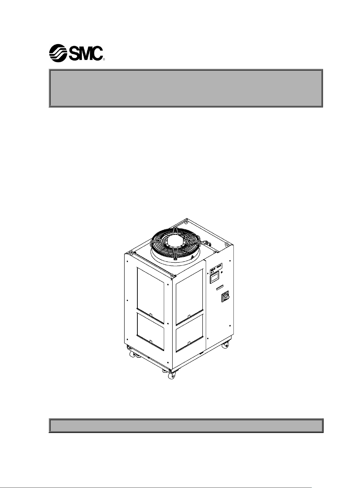
Thermo-chiller
Air-Cooled refrigerated type
HRL100-A
HRL200-A
HRL300-A
Operation Manual
Communication function
Keep this manual available whenever necessary
© 2019 SMC CORPORATION All Rights Reserved
Page 2

To Users,
Note: This manual is subject to possible change without prior notice.
Thank you for purchasing SMC’s Thermo chiller (hereinafter referred to as the “product”).
For safety and long life of the product, be sure to read this operation manual (hereinafter referred
to as the “manual”) and clearly understand the contents.
● Be sure to read and follow all instructions noted with “Warning” or “Caution” in this manual.
● This manual is intended to explain the installation and operation of the product. Only people
who understand the basic operation of the product through this manual or who performs
installation and operation of or have basic knowledge about industrial machines are allowed to
work on the product.
●This manual and other documents do not constitute a contract, and will not affect any existing
agreements or commitments.
● It is strictly prohibited to copy this manual entirely or partially for the use by the third party
without prior permission from SMC.
Page 3

HRX-OM-W069
Contents
Contents
Chapter 1 Read before using ............................................................ 1-1
1.1 Operation mode and operation method ................................................................. 1-1
1.2 Change of operation mode ..................................................................................... 1-3
1.3 Communication port ............................................................................................... 1-4
1.4 Touch panel flow ..................................................................................................... 1-5
Chapter 2 Contact input/output communication /Analog output
communication ...................................................................................... 2-1
2.1 Precautions for communication ............................................................................. 2-1
2.1.1 Precautions wiring communication ...................................................................................... 2-1
2.1.2 Precautions after wiring and before communication ............................................................ 2-2
2.2 Communication specification ................................................................................. 2-2
2.3 Contact input signal ................................................................................................ 2-5
2.3.1 Setting of contact input signal type and form ....................................................................... 2-5
2.3.2 Run/stop・Run・Stop・External switch signal ......................................................................... 2-7
2.3.3 External switch signal ........................................................................................................... 2-8
2.4 Contact output signal ............................................................................................ 2-10
2.4.1 Contact output signal 1 to 3 ...............................................................................................2-10
2.4.2 Contact output signal 4 to 6 ............................................................................................... 2-11
2.5 Analog output signal ............................................................................................. 2-14
Chapter 3 Serial communication ...................................................... 3-1
3.1 Precautions wiring communication ....................................................................... 3-1
3.2 Connected explanation ........................................................................................... 3-1
3.3 Communication specification ................................................................................. 3-2
3.4 MODBUS communication function ........................................................................ 3-3
3.5 Precautions for communication ............................................................................. 3-4
3.5.1 Precautions after wiring and before communication ............................................................ 3-4
3.5.2 Precautions for communicating ............................................................................................ 3-4
3.6 Setting method ........................................................................................................ 3-5
3.7 Communication sequence ...................................................................................... 3-7
3.8 Message configuration ........................................................................................... 3-7
3.8.1 Message frame .................................................................................................................... 3-7
3.9 Function codes ........................................................................................................ 3-9
3.10 Checksum calculation method ............................................................................... 3-9
3.10.1 LRC(ASCII) .......................................................................................................................... 3-9
3.10.2 CRC(RTU) ..........................................................................................................................3-10
3.11 Explanation of function codes ............................................................................. 3-12
3.11.1 Function code:04 Reading multiple registers ....................................................................3-12
3.11.2 Function code:06 Writing registers ....................................................................................3-14
3.11.3 Function code:16 Writing multiple registers ......................................................................3-15
3.12 Negative response ................................................................................................ 3-16
HRL Series
Page 4

HRX-OM-W069
Contents
3.13 Register Map ................................ ................................................................ .......... 3-18
3.13.1 Circulating fluid discharge temperature ............................................................................. 3-19
3.13.2 Circulating fluid electrical conductivity ............................................................................... 3-19
3.13.3 Circulating fluid discharge pressur .................................................................................... 3-19
3.13.4 Circulating fluid flow rate ................................................................................................... 3-19
3.13.5 Status flag .......................................................................................................................... 3-20
3.13.6 Alarm flag........................................................................................................................... 3-21
3.13.7 Data display ....................................................................................................................... 3-22
3.13.8 Circulating fluid set temperature ........................................................................................ 3-22
3.13.9 Operation instruction ......................................................................................................... 3-23
3.13.10 Data instruction .................................................................................................................. 3-23
Chapter 4 Communication alarm function ...................................... 4-1
4.1 Communication alarm occurs ................................................................................. 4-1
4.2 Communication alarm reset .................................................................................... 4-2
4.3 Setting method ......................................................................................................... 4-2
HRL Series
Page 5
1-1
Chapter 1 Read before using
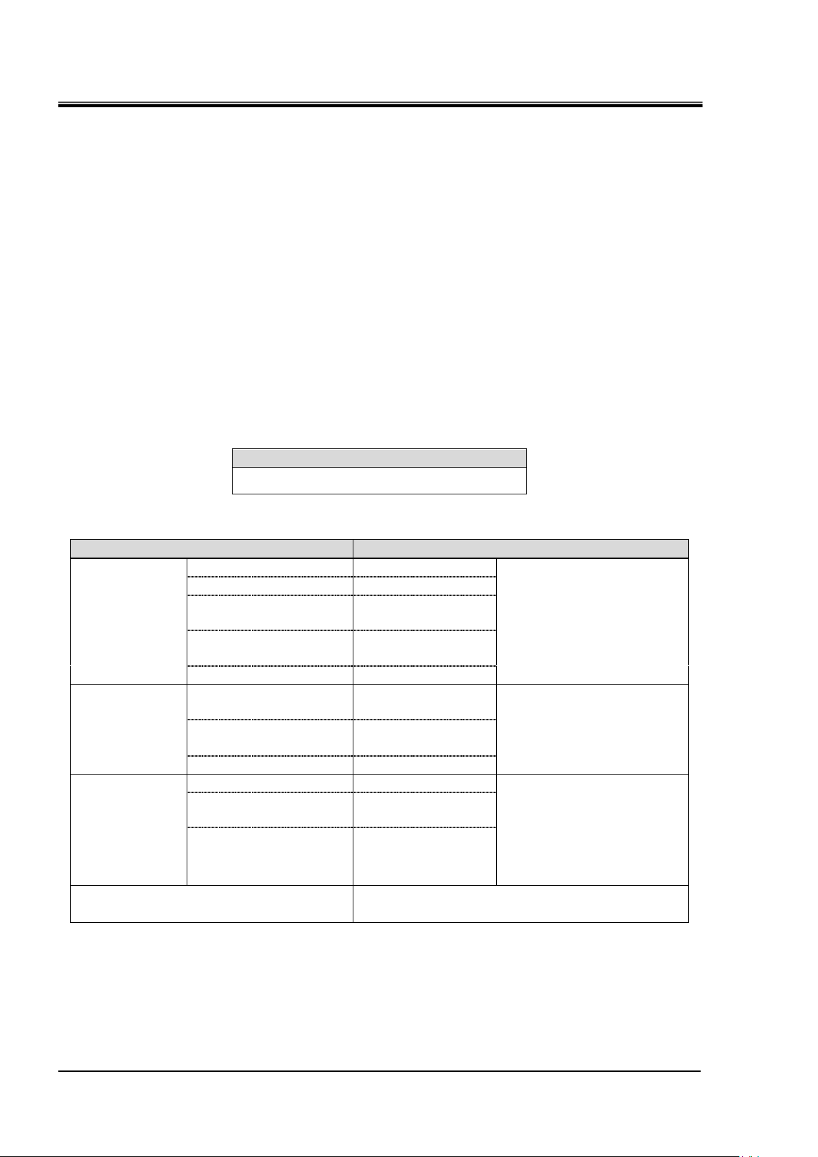
Contact input/output communication /
Analog output communication
This product is equipped with a terminal which
runs/stops the product by remote control and a terminal
which can pick up alarm signals. The terminals can be
changed depending on the customer’s application.
Serial
communication
MODBUS standard
protocol
Serial communication (RS-485/RS232C) enables remote
control of run/start of the product, temperature setting,
and details of product condition and alarm condition can
be obtained.
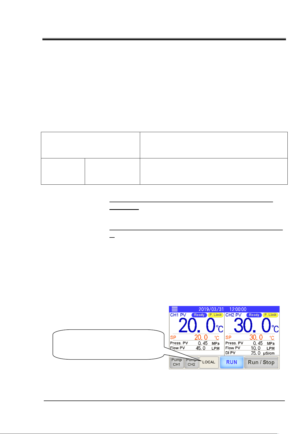
・Displays the current operation mode.
・You can change the operation mode
by pressing it.
The communication of this device consists of contact input/output
communication and analog output communication and serial
communication.
・ The serial communication protocol is a MODBUS communication.
Depending on the customer’s specification, communication can
be changed to contact input/output communication or serial
communication.
Table 1-1 Communication method
HRX-OM-W069
Chapter 1 Read before using
●If using contact input/output communication, refer to
chapter 2.
●If using serial communication MODBUS, refer to chapter
3.
1.1 Operation mode and operation method
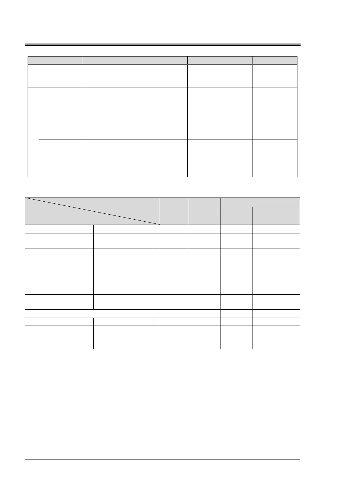
LOCAL, DIO and SERIAL are available as the operation modes. Table
1.1-1 explains the operation modes. The default setting is LOCAL.
The operation method depends on the operation mode. Table 1.1-2
shows how the operation mode and method of operation are related.
Operation mode display and setting
HRL Series 1.1 Operation mode and operation method
Page 6
HRX-OM-W069
1-2
Operation ode
Explanation
Contents
Display
LOCAL
Run / stop and circulating
fluid temperature setting are
possible with the touch panel.
Set the operation
mode to "LOCAL".
To display
the "LOCAL"
DIO
Run / stop by contact input.
Circulating fluid temperature
setting is done at the touch panel.
Set the operation
mode to "DIO".
To display
the "DIO"
SERIAL
Run / stop and circulating
fluid temperature setting are
possible with the serial
communication(RS-232C,RS-485)
Set the operation
mode to "SERIAL".
To display
the "SERIAL"
DIO
Run/Stop
Run / stop by contact input.
Set circulating fluid temperature
by serial communication.
Set to "SERIAL"
mode and set "DIO
Run / Stop" in
"Serial Setting" to
"ON" (enabled).
To display
the "SERIAL
(DIO Run)".
Operation mode
Operation
LOCAL
DIO
SERIAL
DIO
Run/Stop
Touch panel
Run/Stop
○ × ×
×
Touch panel
Circulating fluid
temperature setting
○ ○ ×
×
Touch panel
Settings other than
circulating fluid
temperature setting
○ ○ ○
○
Touch panel
Condition reading
○ ○ ○
○
Contact input/output
communication
Run/Stop
× ○ ×
○
Contact input/output
communication
Condition reading
○
○1 ○ ○1
Reading of the external switch
○ ○ ○
○
Serial communication
Run/Stop
× × ○
×
Serial communication
Circulating fluid
temperature setting
× × ○
○
Serial communication
Condition reading
○ ○ ○
○
Chapter 1 Read before using
Table 1.1-1 Operation modes.
Table 1.1-2 Operation mode and operation
1 Only one external switch can be connected
1.1 Operation mode and operation method
HRL Series
Page 7
1-3
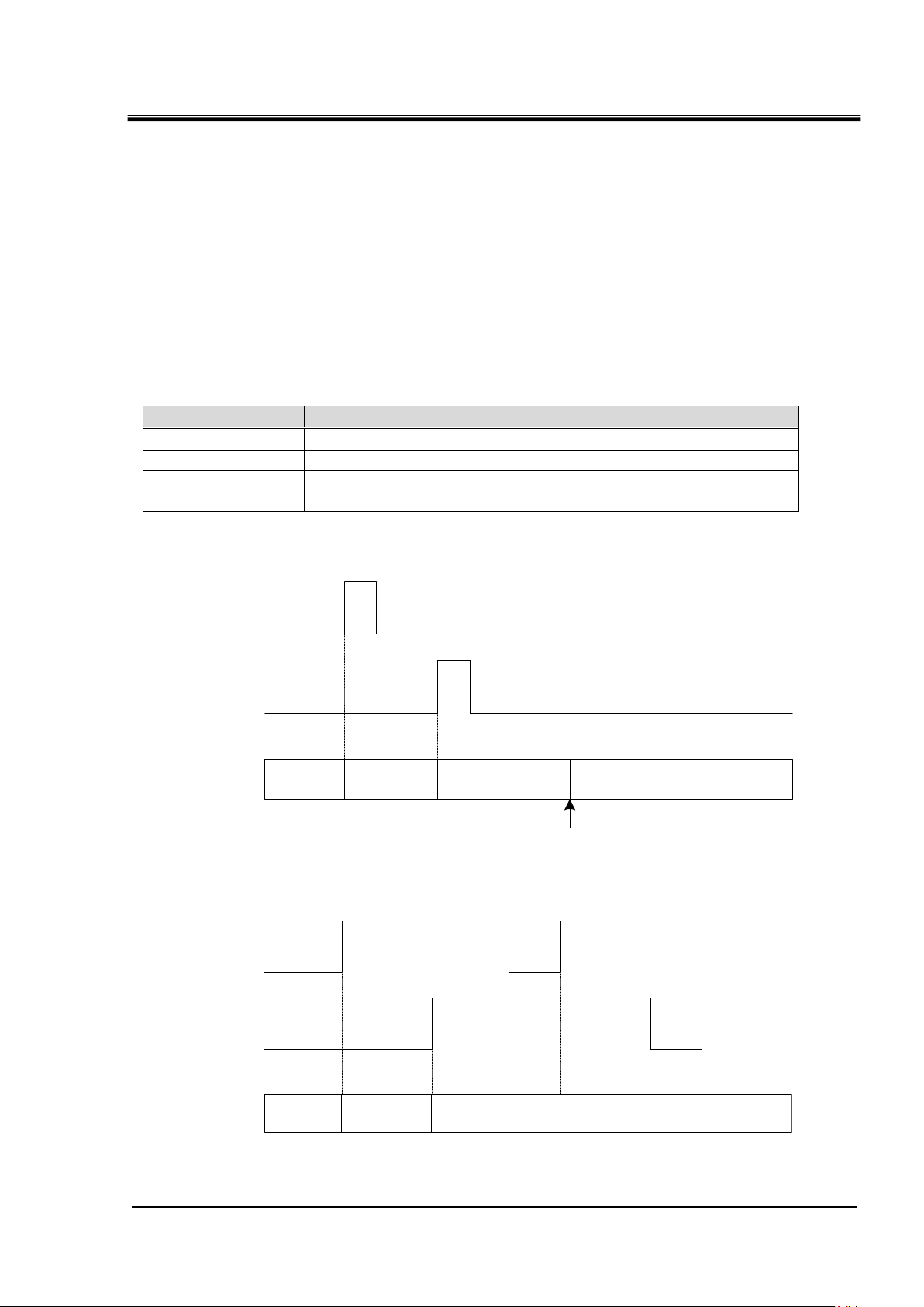
Operation mode
Operation mode change method
LOCAL
None1
DIO
Input the mode request signal (OFF to ON) to contact input 3.
SERIAL
The mode request flag is turned from OFF to ON by serial
communication.2
LOCAL DIO SERIAL LOCAL
Contact input 3
Mode request signal
Serial communication
Mode request flag
Select the LOCAL in the touch panel
Operation
mode
LOCAL DIO SERIAL DIO SERIAL
Contact input 3
Mode request signal
Serial communication
Mode request flag
Operation
mode
HRX-OM-W069
Chapter 1 Read before using
1.2 Change of operation mode
There are the following methods to change the operation mode.
・ Change by touch panel
・ Change by mode request
■About mode request
The mode request, is the ability to change the operation mode by the
contact input or serial communication.
When switching from OFF to ON for both contact input and serial
communication, the mode request becomes effective and the
operation mode changes.
Table 1.2-1 Operation mode change by mode request
1 Change to LOCAL mode is possible only from touch panel operation.
2 When "DIO Run / Stop" is set in advance by the touch panel, run / stop is performed by the contact
input signal.
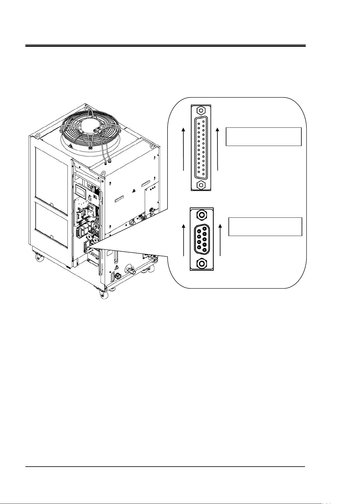
Fig. 1-1 Communication port
Fig.1-2 Mode switching by the mode request (ON state mixed)
HRL Series 1.2 Change of operation mode
Page 8
HRX-OM-W069
1-4
Contact input / output
signal connector
D sub 25 female pin
(socket) type
Serial communication
connector
D sub 9 female pin
(socket) type
13
1
25
14
5
1
9
6
Chapter 1 Read before using
1.3 Communication port
The communication port In the lower left of the electrical component
box is used for communication.
Fig.1-3 shows the location of the communication port.
Fig.1-3 Communication port
1.3 Communication port
HRL Series
Page 9
1-5
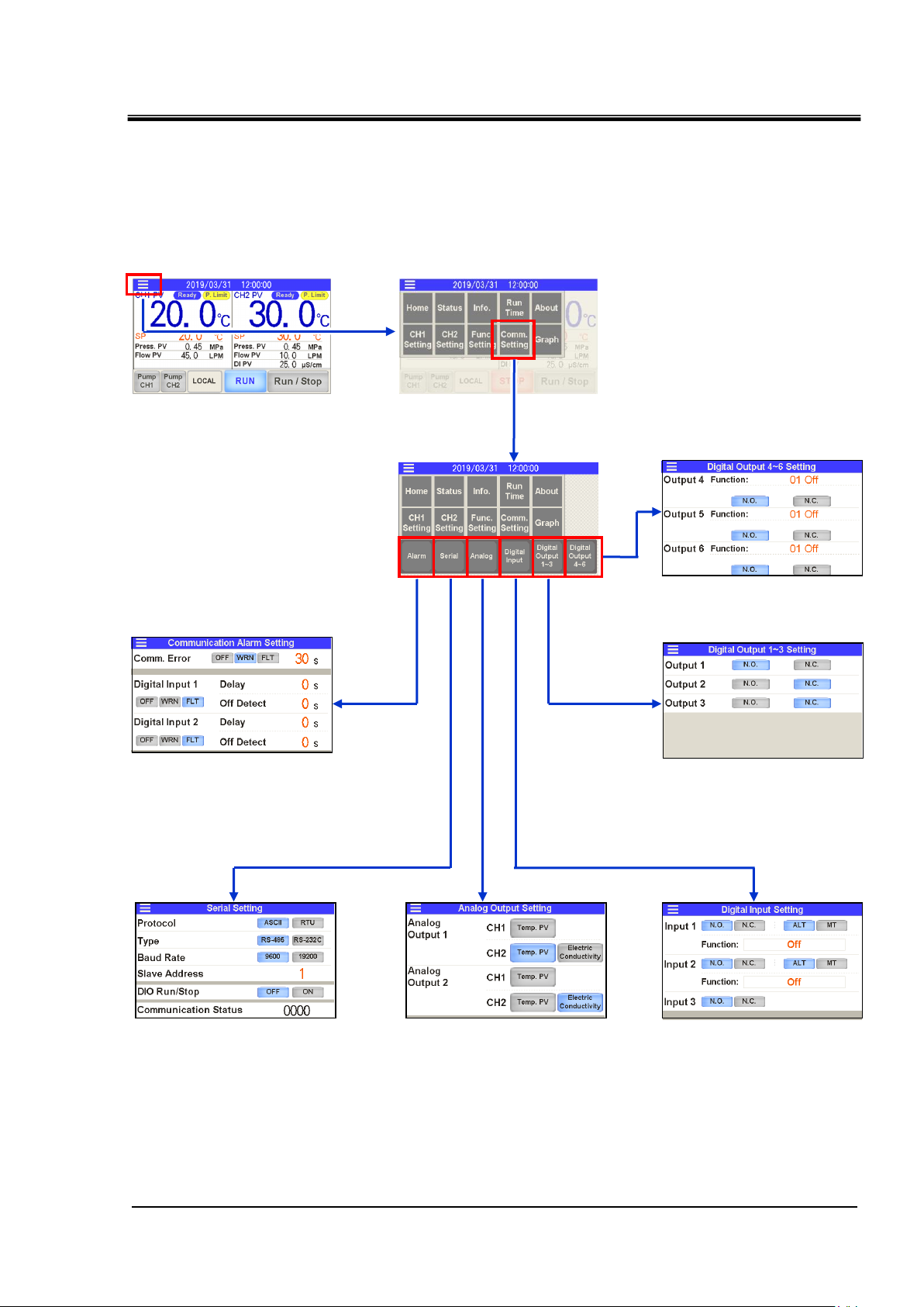
1.4 Touch panel flow
Menu
1. Communication error (AL34)
Detection of contact input signal
Setting for alarm (AL30 and AL31)
3. Analog output setting
4. Setting for contact
input signal 1 to 3
2. Serial communication setting
5. Setting for contact
output signal 1 to 3
6. Setting for contact
output signal 4 to 6
Various screens
Press the [Comm. Setting] on the menu, make the communication
settings from the various setting screens.
Fig.1-4 Communication setting touch panel flow
HRX-OM-W069
Chapter 1 Read before using
HRL Series 1.4 Touch panel flow
Page 10

HRX-OM-W069
1-6
Chapter 1 Read before using
1.4 Touch panel flow
HRL Series
Page 11

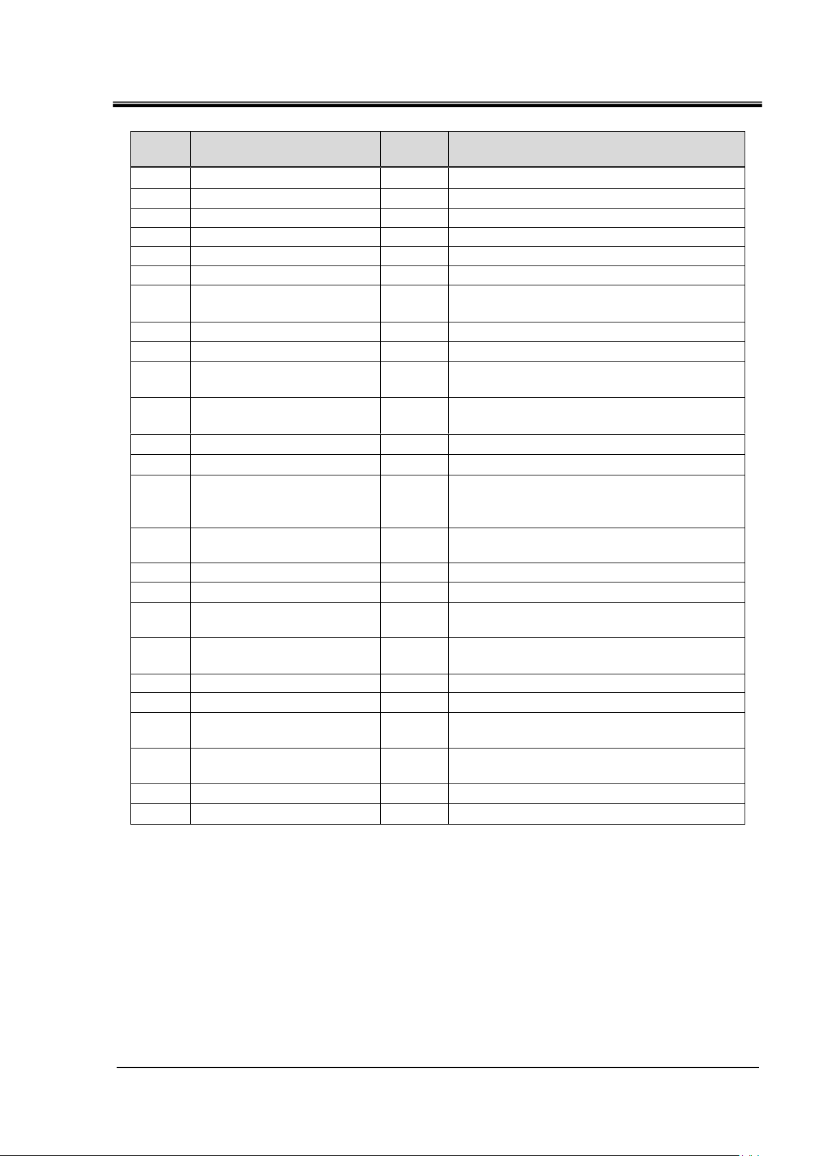
Chapter 2 Contact input/output communication /Analog output communication
2-1
Signal content
Contact input 1
Contact input 2
Contact input 3 Mode request signal only (momentary)
Contact output 1
・Output operation status (RUN / STOP) signal *1
・Selectable contact type (normally open / normally closed)
Contact output 2
・Output the operation stop "FLT" alarm signal *1
・Selectable contact type (normally open / normally closed)
Contact output 3
・Output the continued operation "WRN" alarm signal *1
・Selectable contact type (normally open / normally closed)
Contact output 4
Contact output 5
Contact output 6
Analog output 1
Analog output 2
Signal
Contact input
3pcs.
・Operation / stop signal, Allowed input an external switch signal
・Selectable signal configuration (Alternate/Momentary)
・Selectable contact type (normally open / normally closed)
Contact output
6 pcs.
・Selectable signal content(Refer to “2.4 Contact output signal)
・Selectable contact type (normally open / normally closed)
Analog output
2pcs.
Selectable from the following 3 points
・CH1 Circulating fluid discharge temperature
・CH2 Circulating fluid discharge temperature
・CH2 Circulating fluid electric conductivity
Chapter 2 Contact input/output
communication /Analog
output communication
The device is equipped with a terminal which runs/stops the product. It is also
equipped with a terminal which picks up operation signals, alarm signals and setting
condition.
The device starts contact input/output communication according to the setting of the
operation display panel. Contact input/output communication can be customized by
changing the settings. The contact input / output signals and analog output signals
that this product is equipped with are shown in Table 2-1.
Table 2-1 Contact input / output signal and analog output signal
HRX-OM-W069
1 Signal the contents of the contact output 1 to 3 is a fixed value.
It is not possible to change the content of the signal.
2.1 Precautions for communication
2.1.1 Precautions wiring communication
○Communication wiring
A communication cable that connects the product and customer
system is not included with the product. Please prepare according to
“3.2 Connected explanation”.In order to avoid malfunction, do not
connect to any place other than those shown in “3.2 Connected
explanation”.
HRL Series 2.1 Precautions for communication
Page 12
HRX-OM-W069
2-2
Connector specification (this product side)
Dsub 25 pin female (socket) type
Item
Specification
Contact
input
signal1,2,3
Insulation system
Photo coupler
・Run/Stop signal
・External switch signal
・Operation mode request
signal
(Contact input 3 fixed)
Rated input voltage
DC24V
Operating voltage
range
DC21.6V to 26.4V
Rated input
current
5mA TYP
Input impedance
4.7kΩ
Contact output
signal
1,2,3,4,5,6
Rated load voltage
AC48V or less /
DC30V or less
・Signal of operating status
・Alarm signal
・TEMP READY signal
etc 2
Maximum load
current
AC/DC
800mA or less 1
Minimum load current
DC5V 10mA
Analog output
signal 1,2
Output voltage range
0V to +10V
・CH1 Circulating fluid
discharge temperature
・CH2 Circulating fluid
discharge temperature
・CH2 Circulating fluid
electric conductivity
Maximum output
current
10mA
Maximum accuracy
±1.0%F.S. or less
DC24V output voltage
DC24V±10% 200mA MAX 1
(It can not be used for inductive load.)
Chapter 2 Contact input/output communication /Analog output communication
○Power supply
To use the power of the product, the total load current must be 200mA
or less.
2.1.2 Precautions after wiring and before communication
○Check or set the Operation mode by the touch panel.
・Operation mode shall be DIO.
You can read also in the other mode, but you can not run / stop if it
is not DIO mode.
2.2 Communication specification
Table 2.2-1 Contact input/output communication connector
Table 2.2-2 Contact input/output/ analog output communication specification
1 : The total load current must be 800 mA or less. To use the power of the device, the total load current
must be 200 mA or less.
2 : Refer to “2.4.2 Contact output signal 4 to 6”.
2.2 Communication specification
HRL Series
Page 13
Chapter 2 Contact input/output communication /Analog output communication
2-3
PIN
No.
Item
Division
Contents
1
DC24V output
Output
-
2
DC24V input
Input
-
3
Contact input signal 1
Input
Run/Stop 1
4
Contact input signal 3
Input
Operation mode request signal (fix )2
5
Contact output signal 6
Output
OFF1
6
Contact output signal 1
Output
Run status signal [N.O type](fix)2
7
Contact output signal 3
Output
Operation continuation[WRN]alarm
status signal [N.C. type ](fix)2
8
Contact output signal 5
Output
OFF1
9
None
-
Can not connect
10
Analog output signal 2
Output
CH2 Circulating fluid electric
conductivity signal 1
11
Analog output signal 1
Output
CH2 Circulating fluid discharge
temperature signal 1
12
None
-
Can not connect
13
None
-
Can not connect
14
24 COM output
(Common of contact input
signal)
Output
-
15
Common of contact
output signal 1, 2, 3, 4, 5
Output
-
16
Contact input signal 2
Input
External switch signal 1
17
None
-
Can not connect
18
Common of contact
output signal 6
Output
-
19
Contact output signal 2
Output
Operation stop [FLT] alarm status signal
[N.C. type ](fix)2
20
Contact output signal 4
Output
OFF*1
21
None
-
Can not connect
22
Common of contact
output signal 2
Output
CH2 Circulating fluid electric
conductivity GND
23
Common of contact
output signal 1
Output
CH2 Circulating fluid discharge
temperature GND
24
None
-
Can not connect
25
None
-
Can not connect
Table 2.2-3 Contact input/output communicatin /Analog output pin number
HRX-OM-W069
1 : It is possible to change the setting.
2 : You can not change the setting(“N.O type / N.C. type” can be changed).
HRL Series 2.2 Communication specification
Page 14
HRX-OM-W069
2-4
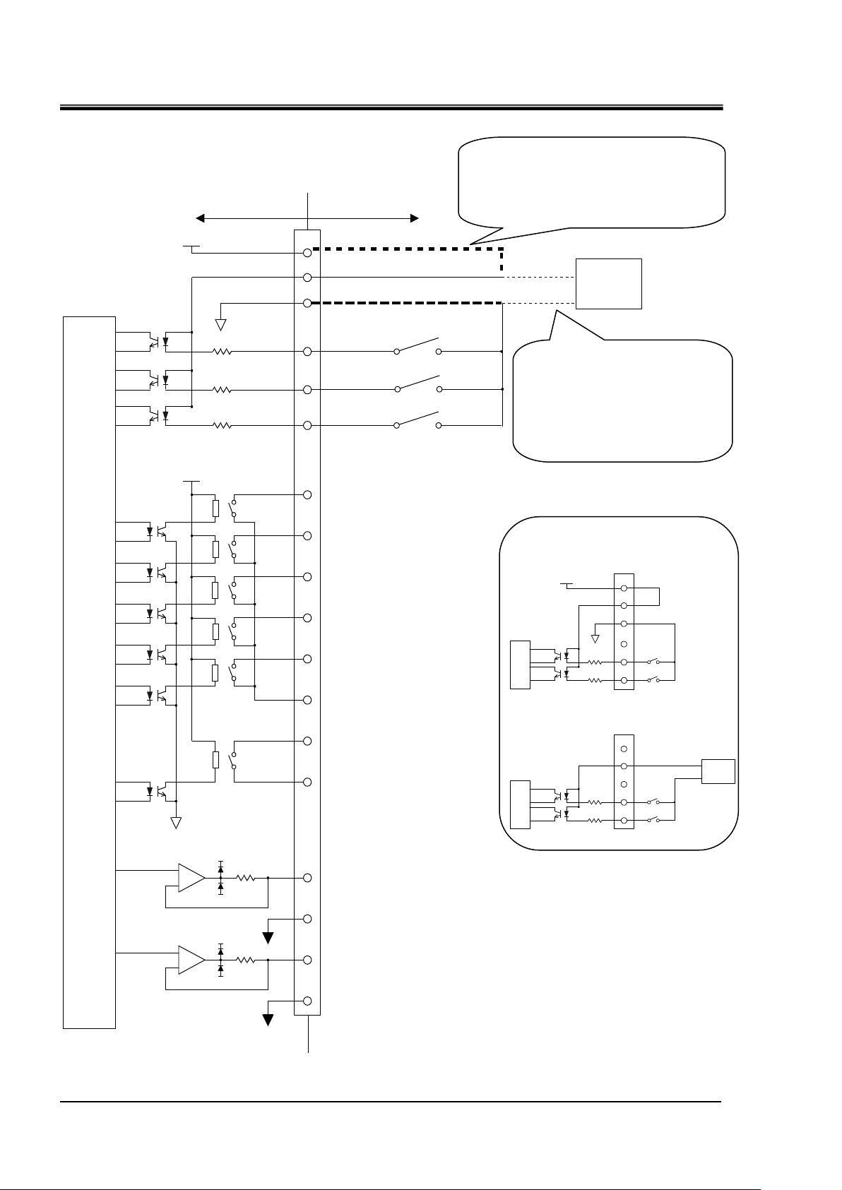
Power supply usage example
Analog output 1 : CH2 Circulating fluid discharge temperature
This product side Customer system side
DC24V
+
-
-15V
100Ω
ANALOG COM
24COM
Contact output 1 : Operation status
1
24COM
DC +24V(output)
4.7kΩ
4.7kΩ
4.7kΩ
+15V
+
-
-15V
100Ω
+15V
ANALOG COM
Internal
circuit
14
3
16
4
6
19
7
20
8
15
5
18
11
23
10
22
Contact output 2 : "FLT"
Contact output 3 : "WRN"
Contact output 4 : OFF
Contact output 5 : OFF
(Momentary)
Run/Stop
Operation mode request
[Warning when an alarm occurs OFF]
[Fault when an alarm occurs OFF]
[Operation ON]
Contact output 6 : OFF
2
DC24V
DC +24V(input)
EXT DC24V
EXT 24COM
Power
supply
Analog output 2 : CH2 Circulating fluid electric conductivity
External switch
24COM(output)
Contact output 1-5 common
Contact output 6 common
Analog output1common
Analog output 2 common
When using this product's power supply,
connect pin 1 to pin 2 and the COM side
of each contact input signal to pin 14.
When using a customer's power
supply, connect the 24V DC +
side to pin 2 and the COM side
of each contact input signal to
the customer's power COM.
DC24V
1
14
3
2
1
14
3
2
Power
supply
DC24V
24COM
4
3
4
This product power supply
usage example
Customer power supply usage example
Chapter 2 Contact input/output communication /Analog output communication
2.2 Communication specification
Fig.2-1 Circuit diagram
HRL Series
Page 15

Chapter 2 Contact input/output communication /Analog output communication
2-5
Setting of contact input signal form
(1)
(2)
(3)
2.3 Contact input signal
There are 3 contact input signals. Two of them can be customized by
the customer.
2.3.1 Setting of contact input signal type and form
The type of contact input signal can be set from the “1.4 Touch panel flow” (Refer
to "4. Contact input signal form" screen).
Following items can be set for contact input signal 1 and 2:
・ Contact type––selects [ N.O. ] (A contact) or [N.C] (B contact)
・ Signal form–––selects [ALT] (alternate) or [MT] (momentary)
・ Signal type–––selects “OFF” (disabled), “external switch” (external switch
signal) or “run/stop” (run/stop) signal., Run (run) signal, Stop
(stop)signal
HRX-OM-W069
HRL Series 2.3 Contact input signal
Page 16

HRX-OM-W069
2-6
No.
Indication
Item
Setting and selection
(1)
Input 1
Contact input
signal 1
Contact
type
1
A contact (normally open)
B contact
(normally closed)
Signal
form
1
Alternate
Momentary
Signal
type
[Off]
Disabled
[External Switch]
External switch signal
[Run/Stop] 1
Run/stop signal
[Run] 2
Run signal
(2)
Input 2
Contact input
signal 2
Contact
type
1
A contact (normally open)
B contact
(normally closed)
Signal
form
1
Alternate
Momentary
Signal
type
[Off]
Disabled
[External Switch] 1
External switch signal
[Run/Stop]
Run/stop signal
[Stop] 2
Stop signal
(3)
Input 3
Contact input
signal 3 3
Contact
type
1
A contact (normally open)
B contact
(normally closed)
Chapter 2 Contact input/output communication /Analog output communication
Table 2.3-1 Setting of contact input signal form
1 : By default.
2 : This setting assigns “run” signal to “contact input 1” and “stop” signal to “contact input 2”.
3 : The signal form of contact input 3 is “momentary”.
2.3 Contact input signal
HRL Series
Page 17

2-7
OFF
ON
Run
Stop
Product condition
Run/stop signal
(Alternate)
O
FF
ON
Run
Stop
Product condition
Run/stop signal
(Momentary)
O
FF
ON
Run
Stop
Product condition
Run signal
O
FF
ON
Stop signal
②
①
③
Chapter 2 Contact input/output communication /Analog output communication
2.3.2 Run/stop・Run・Stop・External switch signal
1) Run/stop signal (Signal type: Alternate)
The product keeps operating while the input signal from the customer is ON.
2) Run/stop signal (Signal type: Momentary)
The state changes when the input signal from the customer goes ON. This signal
operates while the product is stopped, and stops while the product is being operated.
3) Run signal (Signal type: Alternate) /Stop signal (Signal type:Alternate)
Digital input signal 1 is for Run signal(Signal type:Alternate), digital input signal 2 is
for stop signal(Signal type: Alternate). Stop signal becomes valid when both signals are
turned ON.
(1) The product starts operation when the contact input signal 1 is turned ON.
(2) The product stops operation when the contact input signal 2 is turned ON.
(3) The product starts operation because the contact input signal 1 is turned ON
although the contact input signal 2 is OFF.
HRX-OM-W069
HRL Series 2.3 Contact input signal
Page 18

HRX-OM-W069
2-8
“Delay” time
Monitoring method
0sec
Continuous monitoring
1 to 300sec
Monitoring during operation
O
FF
ON
Run
Stop
Product condition
O
FF
ON
External switch signal
[Off Detection] time
③
④ ① ②
Run/Stop signal
[Delay] time
Chapter 2 Contact input/output communication /Analog output communication
4) Digital input signal 1 is for Run/Stop signal (Signal type: Alternate), digital input signal
2 is for external switch signal (Signal type: Alternate).Refer to Chapter 2.3.3 for details of
the external switch.
(1) The product starts operation when the Run/Stop signal from the user is turned ON.
(2) It reads the signal of the external switch signal (N.O type) after the time which has
been set for the [Delay] time.
(3) When the external switch signal (N.O. type) has been turned off for the time set for
[Off Detection] time, it is recognized as OFF.
(4) Alarm [AL31:Contact input 2 signal detection] is generated. The operation of the
product stops.
(5) The product stops operation when the Run/Stop signal is turned OFF during
operation. Afterwards, the alarm is not generated even if the external switch signal
is turned OFF.
2.3.3 External switch signal
The product has two contact inputs available to detect the contact input signal.
This allows reading and monitoring the contact signal from an external switch.
When inputting an external switch signal to the contact input, select “External
Switch” (external switch signal) for the type of contact input signal.(Refer to
“2.3.1 Setting of contact input signal type and form”)
If an input from an external switch is detected, it can be generated as an
alarm.Options to select “continuous monitoring” or “monitoring during
operation” are available. Also, the detection start time after the start of
operation and the detection end time can be set.
・ If the signal of “contact input 1” is detected: the alarm “AL30: Detection
of contact input 1 signal” is activated.
・ If the signal of “contact input 2” is detected: the alarm “AL31: Detection
of contact input 2 signal” is activated.
・ “Delay” time: sets the start time to detect the contact input signal after
the start of operation.
・ “Off detect” time: sets the time between the detection of the contact input
OFF signal and the activation of the alarm.
Table 2.3-2 Monitoring method for contact input signal
2.3 Contact input signal
HRL Series
Page 19

HRX-OM-W069
2-9
Run status of this product
Run
Stop
External switch
ON
OFF
Operation start
Signal reading
start
"Delay" time
"Off Detect" time
Alarm
generation
Operation
stops due to
the alarm.
“Delay” time and “off detect” time
(1)
(2)
(3)
Communication error, detection alarme
of contact input signal and setting
Chapter 2 Contact input/output communication /Analog output communication
Set "Delay" time, "Off Detect" time and "Operation at alarm occurrence" of
external switch signal from “1.4 Touch panel flow (Refer to "1. Communication
error (AL34), contact input signal detection alarm (AL30, AL31) setting"screen).
HRL Series 2.3 Contact input signal
You can select the operation of this product when an alarm occurs by the
contact input signal.
・ [WRN]–––Continue operation of the product when an alarm occurs
・ [FLT]–––Stop operation of this product when an alarm occurs
Page 20

HRX-OM-W069
2-10
No.
Indication
Item
Setting and selection
Setting range
(1)
Comm.
Error
Alarm “AL34:
Communication
error”
Disabled
Waiting
time
30 to 600sec
30sec
Operation
continues during
the alarm
Operation stops
during alarm
(2)
Digital Input 1
Alarm “AL30:
Detection of contact
input 1 signal”
Disabled
Delay
0 to 300sec
0sec
Operation
continues during
the alarm
Off Detect
0 to 10sec
0sec
Operation stops
during alarm
(3)
Digital Input 2
Alarm “AL31:
Detection of contact
input 2 signal”
Disabled
Delay
0 to 300sec
0sec
Operation
continues during
the alarm
Off Detect
0 to10sec
0sec
Operation stops
during alarm
(1)
(2)
(3)
Setting of contact output signal 1 to 3
Chapter 2 Contact input/output communication /Analog output communication
Table 2.3-3 Communication error, detection of contact input signal and operation setting
By default
2.4 Contact output signal
There are 6 contact output signals.The setting of the contact output
signal is done by the "5. Contact output signal 1 to 3 Setup" screen
and “1.4 Touch panel flow” (Refer to "6. Contact output signal 4 to 6
setting" screen).
Contact output signal 4 to 6 can be used to change the signal type.
2.4.1 Contact output signal 1 to 3
The contact type of contact output signals 1 to 3 can be set.
Contact output signal is continuously output.
2.4 Contact output signal
HRL Series
Page 21

Chapter 2 Contact input/output communication /Analog output communication
2-11
No.
Indication
Item
Signal type
Setting and selection
(1)
Output 1
Contact output
signal 1
Operation status
signal
A contact
(normally open)
B contact
(normally closed)
(2)
Output 2
Contact output
signal 2
Operation stop
(FLT) alarm status
signal
A contact
(normally open)
B contact
(normally closed)
(3)
Output 3
Contact output
signal 3
Continuous
operation “WRN”
alarm status signal
A contact
(normally open)
B contact
(normally closed)
No.
Indication
Item
Signal type
Contact type
(1)
Output 4
Function
Contact output
signal 4
Select from “Table
2.4-3 Signal type for
contact output signal
4 to 6” [OFF]
A contact (normally open)
B contact
(normally closed)
(2)
Output 5
Function
Contact output
signal 5
A contact (normally open)
B contact
(normally closed)
(3)
Output 6
Function
Contact output
signal 6
A contact (normally open)
B contact
(normally closed)
Setting of contact output signal 4 to 6
(1)
(2)
(3)
Selection of signal type
Table 2.4-1 Setting of contact output signal 1 to 3
By default
2.4.2 Contact output signal 4 to 6
Contact output signal 4 to 6 can be set to "signal type", "contact form".
A “signal type” for contact output signal 4 to 6 can be selected by the
customer. Refer to “ Table 2.4-3 Signal type for contact output signals
4 to 6.“
HRX-OM-W069
Table 2.4-2 Setting of contact output signal 4 to 6
By default
HRL Series 2.4 Contact output signal
Page 22

HRX-OM-W069
2-12
No. Indication Item Contact type Explanation
Normally open
Normally closed
Operation : closed
Stop : closed
DIO mode : closed
DIO mode : open
the time of alarm : closed
the time of alarm : open
the time of alarm : closed
the time of alarm : open
the time of alarm : closed
the time of alarm : open
Maintenance reminders occurred : closed
Maintenance reminders occurred : open
TEMP READY status : closed
TEMP READY status : open
TEMP READY status : closed
TEMP READY status : open
TEMP READY status : closed
TEMP READY status : open
11 EXTERNAL TEMP None - -
Enabled : closed
Enabled : open
Enabled : closed
Enabled : open
Enabled : closed
Enabled : open
Output the input signal as it is
Reverse output of the input signal
Output the input signal as it is
Reverse output of the input signal
Reverse output of the input signal
Selected alarm occurrence : closed
Selected alarm occurrence : open
Selected maintenance
reminders occurred : open
Maintenance reminders
status signal
Anti-freezing setting
status signal
Warming up setting
status signal
Pass through signal of the
contact input signal 1
Pass through signal of the
contact input signal 2
16
Digital Input 2
17
Mode Request Input
Selected maintenance
reminders occurred : closed
19
Select Maintenance
18
Select Alarm
About selectable maintenance reminders
Refer to "Table 2.4-5 List of maintenance reminders".
Output the input signal as it is
Selected alarm status signal
Refer to "Table 2.4-4 List of alarm selection" for selectable alarms.
Mode request input signal(DIO)
(Pass through signal of the
contact input signal 3)
13
ANTI-FREEZING
14
WARMING UP
15
Digital Input 1
10
TEMP OUT
TEMP OUT signal
12
START-UP
Startup setting
status signal
7
Maintenance
9
CH2 TEMP READY
CH2 TEMP READY signal
8
CH1 TEMP READY
CH1 TEMP READY signal
maintenance reminder
status signal
3
DIO Mode
DIO mode signal
4
Fault
5
Warning
Operation stop "FLT" alarm
status signal
Continuing operation “WRN”
alarm status signal
6
Alarm
alarm status signal
1
Off
Disableing
2
Run
Operation status signal
Chapter 2 Contact input/output communication /Analog output communication
Table 2.4-3 Signal type for contact output signal 4 to 6
2.4 Contact output signal
HRL Series
Page 23

HRX-OM-W069
2-13
Alarm No.
Indication
Explanation
AL01
CH1 Low Level FLT
CH1 abnormal low tank fluid level
AL02
CH1 Low Level WRN
CH1 low tank fluid level
AL03
CH2 Low Level FLT
CH2 abnormal low tank fluid level
AL04
CH2 Low Level WRN
CH2 low tank fluid level
AL06
Fan Inverter
Fan failure
AL09
CH1 High Temp. FLT
CH1 abnormal rise of circulating
fluid temperature
AL10
CH1 High Temp.
CH1 circulating fluid temperature rise
AL11
CH1 Low Temp.
CH1 circulating fluid temperature drop
AL12
CH1 TEMP READY ALARM
CH1 TEMP READY alarm
AL13
CH2 High Temp. FLT
CH2 abnormal rise in circulating
fluid temperature
AL14
CH2 High Temp.
CH2 circulating fluid temperature rise
AL15
CH2 Low Temp.
CH2 circulating fluid temperature drop
AL16
CH2 TEMP READY ALARM
CH2 TEMP READY alarm
AL17
CH1 HX In High Temp. FLT
CH1 abnormal rise in heat exchanger
inlet temperature
AL18
CH1 Press. Sensor
CH1 failure of circulating fluid
discharge pressure sensor
AL19
CH1 High Press.
CH1 circulating fluid discharge pressure rise
AL20
CH1 Low Press.
CH1 circulating fluid discharge pressure drop
AL21
CH2 Press. Sensor
CH2 failure of circulating fluid
discharge pressure sensor
AL22
CH2 High Press. Error
CH2 abnormal rise in circulating fluid
discharge pressure
AL23
CH2 High Press.
CH2 circulating fluid discharge pressure rise
AL24
CH2 Low Press.
CH2 circulating fluid discharge pressure drop
AL25
CH2 Low Press. Error
CH2 abnormal drop in circulating
fluid discharge pressure
AL26
CH2 Flow Sensor
CH2 failure of circulating fluid discharge
flow sensor
AL27
CH2 High Electric Conductivity
CH2 electric conductivity increase
AL30
Digital Input 1
Contact input 1 signal detection
AL31
Digital Input 2
Contact input 2 signal detection
AL34
Communication
Communication error
AL35
Ambient Temp.
Outside of the ambient temperature range
AL36
Maintenance
Maintenance alarm
AL37
Refrigeration Circuit
Compressor circuit failure
AL38
Sensor
Sensor failure
AL39
Controller
Controller failure
AL40
Compressor Inverter
Compressor inverter error
AL41
Compressor Inverter Comm.
Compressor inverter communication error
AL42
CH1 Pump Inverter
CH1 pump inverter error
AL43
CH1 Pump Inverter Comm.
CH1 pump inverter communication error
AL44
CH2 Pump Inverter
CH2 pump inverter error
AL45
CH2 Pump Inverter Comm.
CH2 pump inverter communication error
Chapter 2 Contact input/output communication /Analog output communication
Table 2.4-4 List of alarm selection
Refer to Operation Manual “Installation ・ Operation”.
HRL Series 2.4 Contact output signal
Page 24

HRX-OM-W069
2-14
Maintenance No.
Indication
Explanation
MT01
CH1 Pump
CH1 pump maintenance
MT02
Compressor
Compressor maintenance
MT03
Fan
Fan maintenance
MT04
Dustproof Filter
Dust-proof filter maintenance
MT05
DI Filter
CH2 DI filter maintenance
MT06
CH2 Pump
CH2 pump maintenance
MT07
Low Battery
Battery maintenance
MT08
CH1 Pressure Sensor
Maintenance for CH1 circulating fluid
discharge pressure sensor
MT09
CH2 Pressure Sensor
Maintenance for CH2 circulating fluid
discharge pressure sensor
MT10
CH2 Flow Sensor
Maintenance for CH2 circulating fluid
flow sensor
Setting of analog output signal
(1)
(2)
Chapter 2 Contact input/output communication /Analog output communication
Table 2.4-5 List of maintenance reminders
Refer to Operation Manual “Installation ・ Operation”.
2.5 Analog output signal
The product has two analog outputs.
Setting of the analog output signal is done by the "1.4 Touch panel
flow” (Refer to "3. Analog Output Settings" screen).
The following signals can be output as analog signals:
・ Analog output signal 1––“CH1 circulating fluid discharge
temperature”,“CH2 circulating fluid
discharge temperature” or “circulating fluid
electric conductivity”.
・ Analog output signal 2–– “CH1 circulating fluid discharge
temperature”, “CH2 circulating fluid
discharge temperature” or “circulating
fluid electric conductivity”.
2.5 Analog output signal
HRL Series
Page 25

2-15
No. Indication Item Output
CH1 circulating fluid
discharge temperature
0ºC to 100ºC: 0 to 10.0 V
CH2 circulating fluid
discharge temperature
0ºC to 100ºC: 0 to 10.0 V
CH2 circulating fluid
electrical conductivity
0.1 to 50.0 μS/cm: 0.02 to 10.0 V
CH1 circulating fluid
discharge temperature
0ºC to 100ºC: 0 to 10.0 V
CH2 circulating fluid
discharge temperature
0ºC to 100ºC: 0 to 10.0 V
CH2 circulating fluid
electrical conductivity
0.1 to 50.0 μS/cm: 0.02 to 10.0 V
Setting, selection and display
(1)
Analog output signal 1
(2)
Analog output signal 2
Analog
Output 1
Analog
Output 2
By default
HRX-OM-W069
Chapter 2 Contact input/output communication /Analog output communication
Table 2.5-1 Setting of analog output signal
HRL Series 2.5 Analog output signal
Page 26

HRX-OM-W069
2-16
Chapter 2 Contact input/output communication /Analog output communication
2.5 Analog output signal
HRL Series
Page 27

Chapter 3 Serial communication
3-1
2
SD+
5
SG 7 SD-
SD+
SD-
SG
Terminal
Master
This product
(first slave)
2
SD+
5
SG 7 SD-
This product
(second slave)
2
SD+
5
SG 7 SD-
This product
(31 slaves)
st
resistance
resistance
Terminal
Do not connect any wire to other PIN numbers.
Chapter 3 Serial communication
Serial communication (RS-485/RS232C) enables the remote control of
run/start of the product, temperature setting and details of product
condition, and alarm condition can be obtained.
The operating state of the product (run/stop) and the temperature
setting can be monitored by sending a request message made by the
program of the host computer (e.g. PC).
The communication protocol is MODBUS protocol.
3.1 Precautions wiring communication
○Communication wiring
A communication cable that connects the product and customer
system is not included with the product. Please prepare a cable,
referring to 3.2 ‘’Connected explanation’’ In order to avoid malfunction,
do not connect to any place other than those shown in 3.2 ‘’Connected
explanation’’.
HRX-OM-W069
3.2 Connected explanation
Fig.3-1 shows the wiring when RS-485 is selected as the
communication standard. Fig3-2 shows the wiring when RS-232C is
selected.
A communication cable that connects the product and customer
system is not included with the product. Prepare a cable, referring to
Fig.3-1 or Fig 3-2.
Fig 3-1 RS-485 connector connection
HRL Series 3.1 Precautions wiring communication
Page 28

HRX-OM-W069
3-2
Item
Specification
Connector type (for the product)
D-sub9P type Female connector
Standard
Select from EIA RS-485/RS-232C
Circuit type Half duplex
Half duplex
Transmission type
Start-stop
Protocol
MODBUS terminal1
Terminal resistance
None
2
3
5
RD
SD
SG
2
3
5
RD
SD
SG
Master This product
Do not connect any wire to other PIN numbers.
Chapter 3 Serial communication
[Tips]
・1 master : 1 product, or 1 master: N products.
In the latter case, up to 31 products can be connected.
・Both ends of the communication connection (the end nodes) need to
be connected to the higher level computer.
Fig 3-2 RS-232C connector connection
3.3 Communication specification
Table 3.3-1 Serial communication specification
・ :Default setting
1:Refer to Modicon Co. protocol specifications "PI-MBUS-300 Rev.J".
3.3 Communication specification HRL Series
Page 29

3-3
Table 3.3-2 Communication specification of MODBUS communication function
Item
Specification
Standard
Select from EIA RS-485/RS-232C
Communication speed
Select from 9600bps/19200bps
Data・bit length
7bit(ASCII) / 8bit(RTU)
Stop・bit length
1bit
Data transfer direction
LSB
Parity
Even parity
Letter code
ASCII character string (ASCII) / Binary data(RTU)
Node type
Slave (Controller)
Slave address set range
Select from 1 to 32 address
Error check
LRC method (ASCII) / CRC method (RTU)
・ :Default setting
3.4 MODBUS communication function
MODBUS protocol is a communication protocol developed by Modicon.
It is used to communicate with a PC or PLC.
Register content is read and written by this communication protocol.
HRX-OM-W069
Chapter 3 Serial communication
This communication has the following features.
・Controls run/stop.
・Sets and reads the circulating fluid set temperature.
・Reads the circulating fluid discharge temperature.
・Reads the circulating fluid discharge pressure.
・Reads the circulating fluid flow rate.
・Reads the circulating fluid electric conductivity(CH2 only).
・Reads the condition of the product.
・Reads the alarm generating condition of the product.
・The operation mode can be switched to "SERIAL" mode.
・You can reset the alarm.
Refer to “3.13 Register Map” for the register of the product.
HRL Series 3.4 MODBUS communication function
Page 30

HRX-OM-W069
3-4
Chapter 3 Serial communication
3.5 Precautions for communication
3.5.1 Precautions after wiring and before communication
○Check or set the each communication setting by the touch panel.
・The communication specification shall be the customer’s
communication standard.
・The operation mode shall be the SERIAL mode. (When mode
request flagis activated, SERIAL mode is selected. Refer to 3.13.9).
Other modes can perform reading, but only SERIAL mode can perform
writing.
○Check or set the communication parameters using the touch panel.
Check or set the communication speed so that the product ynchronizes
with the host computer (master) prepared by the customer.
○Check the slave address by the touch panel.
No response is returned when a request message is sent from a slave
address other than those set in the product.
3.5.2 Precautions for communicating
○Allow a suitable interval between requests.
To send request messages in series, wait for 100 msec. or longer after
receiving a response message from the product before sending the
next message.
○Retry (resend request message).
The response may not be returned due to noise. If no message is
returned 1sec. after sending a request message, resend the request
message.
○If necessary send a read request message to check if it was written
correctly.
Message to notify the completion of the process is returned when the
action for the written request message is completed.
Send a read request message to confirm if the setting was written as
requested.
○Setting limit of circulating fluid temperature
When the circulating fluid set temperature is written by communication,
the data is stored in FRAM. When the product restarts, it restarts with
the value which was set before the restart. The number of times it is
possible to overwrite FRAM is limited. Data is only stored in FRAM
when it receives a circulating fluid set temperature which is different
from the previous temperatures. Please check how many times it is
possible to overwrite FRAM, and avoid unnecessary changes of the
circulating fluid set temperature during communication
3.5 Precautions for communication HRL Series
Page 31

3-5
3.6 Setting method
No.
Indication
Item
Setting, selection and display
Default setting
(1)
Protocol
Communication
format
ASCII code
○
Binary data
-
(2)
Type
Standard
EIA RS-485
○
EIA RS-232C
-
(3)
Baud Rate
Communication
speed
9600 bps
-
19200 bps
○
(4)
Slave Address
Slave address
1 to 32
Select from
1 to 32
1
(5)
DIO Run/Stop 1
“Run/stop” by
contact input
Disabled
○
Enabled
-
(6)
Communication
Status
Communication
status 2
0000
Displays the
communication
status
-
Serial communication setting
(1)
(2)
(3)
(4)
(5)
(6)
Set of serial communication is done from “1.4 Touch panel flow”
(Refer to "2. Serial communication settings" screen).
Table 3.6-1 Setting of serial communication
HRX-OM-W069
Chapter 3 Serial communication
1 “Run/stop” operation of the product is carried out by the contact input signal, and by
reading/writing the “change in set value of circulating fluid temperature” and “operation status”
by serial communication.
2 It is a function to display the status of serial communication. Slave address mismatch or register
map of this product display relevant contents for communication nonconformities, such as
accessing outside the area.The table3.6-2 shows the display and its contents.
HRL Series 3.6 Setting method
Page 32

HRX-OM-W069
3-6
Communication setting
Contents
8001
Normal message
4801
An abnormal number of data has been sent from the customer
device.
4401
This product is trying to access to the outside address of the
register map that support.Or trying to write to read-only address.
4201
Function code that this product does not support is being sent from
the customer's equipment.
0081
The slave addresses set for this product and customer's device are
different.
0041
CRC (1) does not match in the RTU settings.
0021
LRC (1) does not match in the ASCII settings.
00XX(2)
Mismatched communication settings(Baud Rate, parity, number of
data bits, etc.)or very short message intervals from customer
equipment.
0000(3)
Bad wiring or no message sent from customer equipment.
Chapter 3 Serial communication
Table 3.6-2 Communication status
(1) CRC(Refer to 3.10.2)、LRC(Refer to 3.10.1)。
(2) “XX” means that it is undefined.
3) Initial state or after the outgoing message is received from the customer, and displays it in case the
message is a state that can not be received was continued for 30 seconds.
3.6 Setting method HRL Series
Page 33

3-7
Customer's system
(host)
This product
(slave)
Request message
Positive response
Request message
Negative response
Request message
No response
10 to 200ms
(
Response message
)
(
Response message
)
3.7 Communication sequence
Starts with a request message from the customer’s system (host), and
finishes with a response message from the product (slave). This
product operates as a slave. It does not send any requests.
●Positive response
●Negative response
●No response
HRX-OM-W069
Chapter 3 Serial communication
Based on the request message, reads
register/writes register and returns a
positive response.
Returns a negative message when the
received request message is not
normal.
Refer to ‘’3.12 Negative response’’.
No response is returned when there is
an error in “slave address specification”
or”Checksum(LRC / CRC)”.
3.8 Message configuration
3.8.1 Message frame
The message configuration is shown below. The communication of this
HRL Series 3.7 Communication sequence
product uses 2 transmission modes, ASCII or RTU.
1) ASCII mode frame
For ASCII mode, the message starts with ASCII characters “:”(3Ah)
and ends with “CR/LF”(0Dh,0Ah). A response message will not be
returned unless the request includes [:] and [CR][LF]. This product
clears all previously received code when [:] is received.
Page 34

HRX-OM-W069
3-8
a)Start
b)Slave
Address
c)Function
d)Data
e) Checksum
(LRC)
f)End
[:]
XX
XX
XX
XX
XX ~ XX
XX
XX
[CR]
[LF]
a)Start
b)Slave
Address
c)Function
d)Data
e) Checksum
(CRC)
f)End
T1-T2-T3-T4
XX
XX
XX ~ XX
XX
XX
T1-T2-T3-T4
Chapter 3 Serial communication
a) Start
b) Slave Address
c) Function (Refer to “3.9 Function codes”)
d) Data
e) LRC
Table 3.8-1 ASCII mode message frame
The start of the message. [:](3Ah) (ASCII)
This is a number to identify this product. “1" is the default setting.
This can be changed by the touch panel.
Command is assigned.
Depending on the function, the address and the number of the
register, the value of reading/writing are assigned.
LRC method
Refer to ‘’3.10.1 LRC(ASCII)’’.
f) END
The end of the message. [CR](0Dh)+[LF](0Ah)
2) RTU mode frame
RTU mode starts from and ends with at least 3.5 characters of silent interval. Silent
interval is indicated by T1-T2-T3-T4.
Table 3.8-2 RTU mode message frame
a) Start
In Modbus RTU mode, message frames are separated by a silent interval
(non-communication time). At least 3.5 characters of silent interval are necessary
at the beginning and the end of the communication frame.
b) Slave Address
This is a number to identify this product. “1" is the default setting. This can be
changed by the touch panel.
3.8 Message configuration HRL Series
c) Function (Refer to “3.9 Function codes”)
Command is assigned.
Page 35

3-9
d) Data
NO
Code
Name
Function
1
04(04h)
read holding registers
Reading multiple registers
2
06(06h)
preset single register
Writing registers1
3
16(10h)
preset multiple registers
Writing multiple registers
Depending on the function, the address and the number of the register, the value
of reading/writing are assigned.
e) CRC
CRC method.
Refer to “3.10.2 CRC(RTU)”.
f )End
3.5 characters of silent interval indicates the end of a message.
3.9 Function codes
Table 3.9-1 shows function codes to read or write register. Refer to
"3.11 Explanation of function codes".
HRX-OM-W069
Chapter 3 Serial communication
Table 3.9-1 Function codes
1 : Broadcast is not supported.
3.10 Checksum calculation method
3.10.1 LRC(ASCII)
LRC checks the content of the message other than [:] of START and
[CR][LF] of END. The sending side calculates and sets. The receiving
side calculates based on the received message, and compares the
calculation result with the received LRC. The received message is
deleted if the calculation result and received LRC do not match.
Consecutive 8 bits of the message are added, and the result without
carry (overflow) is converted to 2's complement.
Calculation example
Example) Change circulating fluid set temperature 23.4 ° C
Sending data 0106004000EA
○Slave Address : No.1
○Function : No.06
○Writing address : 0040h
○Writing data : 00EAh
HRL Series 3.9 Function codes
Page 36

HRX-OM-W069
3-10
No
Classification
Contents
calculation result
1
LRC message for
calculation
0106004000EA
-
2
Calculation
Added for each 8Byte
01h+06h+00h+40h+00h+EAh=131h
31h
3
complement of 2
31h→CEh→CFh
CFh(LRC)
4
Sending message
[:]0106004000EACF[CR][LF]
-
0 0 0 0 0 0 0 0 0 0 0 0 0 0 0 0 0
…
Add 0 to the top
If it is 0, do not ExOR
…
1 bit shift in the lowest direction
0 0 0 0 0 0 0
1
0 0 0 0 0 0 0 0 1
…
…
1 bit shift in the lowest direction
Add 0 to the top
Execute ExOR if 1
Chapter 3 Serial communication
3.10.2 CRC(RTU)
CRC checks the content of the message. The sending side calculates
the data every 2 bytes (16 bits). The receiving side calculates CRC
based on the received message, and compares the calculation result
with the received CRC. The received message is deleted if the
calculated CRC is different from the received CRC.
Calculation procedure
(1) Preload “FFFFh” (set 0xFFFF as initial value ).
(2) Exclusive OR the first byte of the transmitted message with the value in (1).
(3) Shift the result of (2) by one bit toward the least significant bit, and fill a zero
into the most significant bit position.
(4) If the least significant bit was a 1, exclusive OR the result of (3) with “A001h”.
(Example 1). If the least significant bit was a 0, no exclusive OR takes place.
(5) Repeat (3) to (5) until eight shifts have been performed.S
(6) After eight shifts, exclusive OR the result of (5) with the next 1-byte
(2nd. byte).
(7) The processes (3) to (6) are repeated for all the remaining bytes of the
message.
(8) The 2-byte data of the result of (7) is the CRC value
(Example 1) The least significant bit was a 1.
(Example 2) The least significant bit was a 0.
3.10 Checksum calculation method HRL Series
Page 37

HRX-OM-W069
3-11
Data No.
1st value
2nd value
3rd value
4th value
5th value
6th value
Data
contents
0001h
0006h
0000h
0040h
0000h
00EAh
No
Classification
Contents
Result
1
CRC
message for
calculation
0106000B00FE
-
2
Calculation
Perform (1) to (4) for the 1st value (0001h) and then,
perform (5).
807Eh
3
Perform (6) for 2nd value (0006h) and then, perform (5).
2280h
4
Perform (6) for 3rd. value (0000h) and then, perform (5).
A023h
5
Perform (6) for 4th value (0040h) and then, perform (5).
29E0h
6
Perform (6) for 5th value (0000h) and then, perform (5).
8828Eh
7
Perform (6) for 6th value (00EAh) and then, perform (5).
9109h
(CRC)
8
Addition to the
sent message
0106004000EA09911
-
Chapter 3 Serial communication
Calculation example
Example) Change circulating fluid set temperature 23.4 ° C
Sending data 0106004000EA
○Slave Address : No.1
○Function : No.06
○Writing address : 0040h
○Writing data : 00EAh
1 When incorporating it into the message, set it in order of low byte and high byte.
HRL Series 3.10 Checksum calculation method
Page 38

HRX-OM-W069
3-12
Request message 010400300010
Field name
Example
(HEX)
ASCII mode
character data
RTU mode
binary data
Header
-
“:”
None
Slave Address
0x01
“0”,“1”
0x01
Function
0x04
“0”,“4”
0x04
Head address of specified register
0x0030
“0”,“0”,“3”,“0”
0x00,0x30
Quantity of register to read
0x0010
“0”,“0”,“1”,“0”
0x00,0x10
Checksum ASCII:LRC RTU:CRC
-
“B”,”B”
0xF1,0xC9
Trailer
-
CR/LF
None
Total
quantity of byte
17
8
Chapter 3 Serial communication
3.11 Explanation of function codes
3.11.1 Function code:04 Reading multiple registers
Register data of assigned points from assigned address is read.
■ Communication example
○Slave Address : No.1
○Read 16 pieces data from register 0030h.
CH1 Circulating fluid discharge temperature [20.0℃]
CH2 Circulating fluid discharge temperature [25.0℃]
CH2 Circulating fluid electrical conductivity [20.0uS/cm]
CH1 Circulating fluid discharge pressure [45MPa]
CH2 Circulating fluid discharge pressure [0.50MPa]
CH1 Circulating fluid discharge flow rate [45.0LPM]
CH2 Circulating fluid return flow rate [10.0LPM]
Data display 1 to 4 [non-selection (all 0)]
Status flag [during operation, CH1, CH2 TEMP READY status]
Alarm flag 1 to 3 [no alarm]
3.11 Explanation of function codes HRL Series
Page 39

HRX-OM-W069
3-13
Response message
01042000C800FA000000C8002D003201C2006400000000000000000031000000000000
Field name
Example
(HEX)
ASCII mode
character data
RTU mode
binary data
Header
-
“:”
None
Slave Address
0x01
“0”,“1”
0x01
Function
0x04
“0”,“4”
0x04
Quantity of bytes to read
0x20
“2”,“0”
0x20
Information of 0030h
(CH1 Circulating fluid discharge temperature)
0x00C8
“0”,“0”,“C”,“8”
0x00,0xC8
Information of 0031h
(CH2 Circulating fluid discharge temperature)
0x00FA
“0”,“0”,“F”,“A”
0x00,0xFA
Information of 0032h (Reservation)
0x0000
“0”,“0”,“0”,“0”
0x00,0x00
Information of 0033h
(CH2 Circulating fluid electrical conductivity)
0x00C8
“0”,“0”,“C”,“8”
0x00,0xC8
Information of 0034h
(CH1 Circulating fluid discharge pressure)
0x002D
“0”,“0”,“2”,“D”
0x00,0x2D
Information of 0035h
(CH2 Circulating fluid discharge pressure)
0x0032
“0”,“0”,“3”,“2”
0x00,0x32
Information of 0036h
(CH1 Circulating fluid flow rate)
0x01C2
“0”,“1”,“C”,“2”
0x01,0xC2
Information of 0037h
(CH2 Circulating fluid flow rate)
0x0064
“0”,“0”,“6”,“4”
0x00,0x64
Information of 0038h (Data display 1)
0x0000
“0”,“0”,“0”,“0”
0x00,0x00
Information of 0039h (Data display 2)
0x0000
“0”,“0”,“0”,“0”
0x00,0x00
Information of 003Ah (Data display 3)
0x0000
“0”,“0”,“0”,“0”
0x00,0x00
Information of 003Bh (Data display 4)
0x0000
“0”,“0”,“0”,“0”
0x00,0x00
Information of 003Ch (Status flag)
0x0031
“0”,“0”,“3”,“1”
0x00,0x31
Information of 003Dh (Alarm flag 1)
0x0000
“0”,“0”,“0”,“0”
0x00,0x00
Information of 003Eh (Alarm flag 2)
0x0000
“0”,“0”,“0”,“0”
0x00,0x00
Information of 003Fh (Alarm flag 3)
0x0000
“0”,“0”,“0”,“0”
0x00,0x00
Checksum ASCII:LRC RTU:CRC
-
“9”,”A”
0xE7,0xB8
Trailer
-
CR/LF
None
Total
quantity of byte
75
37
Chapter 3 Serial communication
HRL Series 3.11 Explanation of function codes
Page 40

HRX-OM-W069
3-14
Request message 010600420002
Field name
Example
(HEX)
ASCII mode
character data
RTU mode
binary data
Header
-
“:”
None
Slave Address
0x01
“0”,“1”
0x01
Function
0x06
“0”,“6”
0x06
Head address of specified
register
0x0042
“0”,“0”,“4”,“2”
0x00,0x42
Information written to 0042h
(Mode request)
0x0002
“0”,“0”,“0”,“2”
0x00,0x02
Checksum ASCII:LRC RTU:CRC
-
“B”,”5”
0xA8,0x1F
Trailer
-
CR/LF
None
-
Total
quantity of byte
17
8
Response message 010600420002
Field name
Example
(HEX)
ASCII mode
character data
RTU mode
binary data
Header
-
“:”
None
Slave Address
0x01
“0”,“1”
0x01
Function
0x06
“0”,“6”
0x06
Address of register to write
0x0042
“0”, “0”,“4”,“2”
0x00,0x42
Information of register to write
0x0002
“0”,“0”,“0”,“2”
0x00,0x02
Checksum ASCII:LRC RTU:CRC
-
“B”,“5”
0xA8,0x1F
Trailer
-
CR/LF
None
Total
quantity of byte
17
8
Chapter 3 Serial communication
3.11.2 Function code:06 Writing registers
Write data to assigned address.
■Communication example
○Slave Address : No.1
○Write data to register 0042Ch
(The mode request indication)
3.11 Explanation of function codes HRL Series
Page 41

Chapter 3 Serial communication
3-15
Request message 0110004000030600EB015D0001
Field name
Example
(HEX)
ASCII mode
character data
RTU mode
binary data
Header
-
“:”
None
Slave Address
0x01
“0”,“1”
0x01
Function
0x10
“1”,“0”
0x10
Head address of specified register
0x0040
“0”,“0”,“4”,“0”
0x00,0x40
Quantity of register to write
0x0003
“0”,“0”,“0”,“3”
0x00,0x03
Quantity of byte to read
0x06
“0”,“6”
0x06
Information written to 0040h
(CH1 Circulating fluid set temperature)
0x00EB
“0”,“0”,“E”,“B”
0x00,0xEB
Information written to 0041h
(CH2 Circulating fluid set temperature)
0x015D
“0”,“1”,“5”,“D”
0x01,0x5D
Information written to 0042h
(Operation stop flag)
0x0001
“0”,“0”,“0”,“1”
0x00,0x01
Checksum ASCII:LRC RTU:CRC
-
“5”,”C”
0x91,0xAD
Trailer
-
CR/LF
None
Total
quantity of byte
31
15
Response message 011000400003
Field name
Example
(HEX)
ASCII mode
character data
RTU mode
binary data
Header
-
“:”
None
Slave Address
0x01
“0”,“1”
0x01
Function
0x10
“1”,“0”
0x10
Head address of register to write
0x0040
“0”,“0”,“4”,“0”
0x00,0x40
Quantity of register to write
0x0003
“0”,“0”,“0”,“3”
0x00,0x03
Checksum ASCII:LRC RTU:CRC
-
“A”,”C”
0x81,0xDC
Trailer
-
CR/LF
None
Total
quantity of byte
17
8
3.11.3 Function code:16 Writing multiple registers
Register content of assigned points of assigned address is written.
■ Communication example
○Slave Address : No.1
○Write three consecutive data from register 0040h.
CH1 Change of circulating fluid set temperature [23.5℃]
CH2 Change of circulating fluid set temperature [34.9℃]
Operation start instruction
HRX-OM-W069
HRL Series 3.11 Explanation of function codes
Page 42

HRX-OM-W069
3-16
Start
Slave
Address
1)Function
2)Error
Code
LRC
End
[:]
XX
XX
XX
XX
XX
XX
XX
XX
[CR]
[LF]
Start
Slave
Address
1)Function
2)Error
Code
CRC
End
T1-T2-T3-T4
1
XX
XX
XX
XX
XX
XX
T1-T2-T3-T4
Chapter 3 Serial communication
3.12 Negative response
A negative response is returned when the following request message
is received.
1) When unspecified function code is used.
2) An address out of range is specified.
3) The data field is not normal.
Negative response message (Slave to Master)
1) Negative acknowledgment message frame in ASCII mode.
2) Negative acknowledgment message frame in RTU.
1 Silent interval for 3.5 characters
1) Function
Assign the value consisting of the request function code (hexadecimal
value) plus 80h.
Example 1) ASCII mode
Received function code: “04”(0000 0100)” ASCII code 30h, 34h
Abnormal function code: ”84”(1000 0100)” ASCII code 38h, 34h
Example 2) RTU mode
Receive function code: "04" (0000 0100)
Abnormal function code: "84" (1000 0100)
2) Error Code
Assign error code below.
3.12 Negative response HRL Series
01 : Function code of a command is outside the standard
02 : The specified address of register is outside the range.
03 : Data field of a command is not normal.
Page 43

HRX-OM-W069
3-17
Request message 010401000007
Field name
Example
(HEX)
ASCII mode
character data
RTU mode
binary data
Header
-
“:”
None
Slave Address
0x01
“0”,“1”
0x01
Function
0x04
“0”,“4”
0x04
Head address of register out of range
0x0100
“0”,“1”,“0”,“0”
0x01,0x00
Quantity of register to read
0x0007
“0”,“0”,“0”,“7”
0x00,0x07
Checksum ASCII:LRC RTU:CRC
-
“F”,”3”
0xB0,0x34
Trailer
-
CR/LF
None
Total
quantity of byte
16
8
Response message 018402
Field name
Example
(HEX)
ASCII mode
character data
RTU mode
binary data
Header
-
“:”
None
Slave Address
0x01
“0”,“1”
0x01
Function (03h+80h)
0x84
“8”,“4”
0x84
Error Code
(Specified register address is out of range.)
0x02
“0”,“2”
0x02
Checksum ASCII:LRC RTU:CRC
-
“7”,“9”
0xC2,0xC1
Trailer
-
CR/LF
None
Total
quantity of byte
11
5
Chapter 3 Serial communication
■ Communication example
○Slave Address : No 1
○Read seven consecutive data from register 0100h which is out of range.
HRL Series 3.12 Negative response
Page 44

HRX-OM-W069
3-18
Address
Contents
value
R/W
0030h
CH1 Circulating fluid
discharge temperature
Decimal number : -327.6 to 327.6℃
Hexadecimal number : F334h to 0CCCh
(0.1℃/dig)
R
0031h
CH2 Circulating fluid
discharge temperature
Decimal number : -327.6 to 327.6℃
Hexadecimal number : F334h to 0CCCh
(0.1℃/dig)
0032h
Reservation
-
0033h
CH2 Circulating fluid
electrical conductivity
Decimal number : –3276.8 to 3276.7µS/cm
Hexadecimal number : 8000h to 7FFFh
(0.1µS/cm/dig)
0034h
CH1 Circulating fluid
discharge pressure
Decimal number : -32.76 to 32.76MPa
Hexadecimal number : F334h to 0CCCh
(0.01MPa/dig)
0035h
CH2 Circulating fluid
discharge pressure
Decimal number : -32.76 to 32.76MPa
Hexadecimal number : F334h to 0CCCh
(0.01MPa/dig)
0036h
CH1 Circulating fluid
flow rate
Decimal number : -3276.8 to 3276.7LPM
Hexadecimal number : 8000h to 7FFFh]
(0.1LPM/dig)
0037h
CH2 Circulating fluid
flow rate
Decimal number : -3276.8 to 3276.7LPM
Hexadecimal number : 8000h to 7FFFh
(0.1LPM/dig)
0038h
Data display 1
Follow the data instructions1
0039h
Data display 2
Follow the data instructions1
003Ah
Data display 3
Follow the data instructions1
003Bh
Data display 4
Follow the data instructions1
003Ch
Status flag
Refer to 3.13.5 Status flag
003Dh
Alarm flag 1
Refer to 3.13.6 Alarm flag
003Eh
Alarm flag 2
Refer to 3.13.6 Alarm flag
003Fh
Alarm flag 3
Refer to 3.13.6 Alarm flag
0040h
CH1 Circulating fluid
set temperature
Positive number : 0000h to 7FFFh(0.1℃/dig)
Negative number : 8000h to
FFFFh(0.1℃/dig)2
R/W
0041h
CH2 Circulating fluid
set temperature
Positive number : 0000h to 7FFFh(0.1℃/dig)
Negative number : 8000h to
FFFFh(0.1℃/dig)2
0042h
Operation instruction
3(Operation start instruction, mode request,
alarm reset)
0043h
Data instruction
4
Chapter 3 Serial communication
3.13 Register Map
1 Data display(Refer to 3.13.7 Data display)
2 Negative numbers are two's complement representation
3 Operation instruction(Refer to 3.13.9 Operation instruction)
4 Data instruction(Refer to 3.13.10 Data instruction)
3.13 Register Map HRL Series
Page 45

3-19
3.13.1 Circulating fluid discharge temperature
To notify the circulating fluid discharge temperature of the product. (°C
or °F). Read the circulating fluid discharge temperature which is
displayed on the touch panel. (Offset temperature is displayed if offset
function is set).
3.13.2 Circulating fluid electrical conductivity
Notifies the circulating fluid electrical conductivity(CH2 only).
3.13.3 Circulating fluid discharge pressur
To notify the circulating fluid discharge pressure of the product.
3.13.4 Circulating fluid flow rate
To notify the circulating fluid discharge pressure of the product..
HRX-OM-W069
Chapter 3 Serial communication
HRL Series 3.13 Register Map
Page 46

HRX-OM-W069
3-20
Name
Status flag
Bit
15
14
13
12
11
10 9 8 7 6 5 4 3 2 1 0
Bit
Name
Explanation
0
Run flag
Run status
0= Stop 1= Run
1
Operation stop alarm flag
Operation stop alarm given off status
0= Not occurred
1= Operation stop alarm given off
2
Operation continued alarm flag
Operation continued alarm given off status
0= Not occurred
1= Operation continued alarm given off
3
Notice for maintenance
Notice for maintenance status
0 = Not generated 1 = Generated
4
CH1 Completion of preparation
(TEMP READY)flag
Completion of preparation (TEMP READY) status
0= Condition isn’t formed 1= Condition is formed
5
CH1 Completion of preparation
(TEMP READY)flag
Completion of preparation (TEMP READY) status
0= Condition isn’t formed 1= Condition is formed
6
TEMP OUT flag
TEMP OUT status
0= Condition isn’t formed 1= Condition is formed
7
None
-
8
None
-
9
None
-
10
None
-
11
None
-
12
External tuning function flag
External tuning function setting states
0=Stop 1= During setting
13
Warm-up function flag
Warm-up function setting status
0= Unset 1= During setting
14
Startup operation flag
Startup operation setting status
0= Unset 1= During setting
15
Anti-freezing flag
Anti-freezing setting status
0= Unset 1= During setting
Chapter 3 Serial communication
3.13.5 Status flag
The status of the product is read by the following assignment.
Status flag
3.13 Register Map HRL Series
Page 47

3-21
3.13.6 Alarm flag
Name
Alarm flag 1
Bit
15
14
13
12
11
10 9 8 7 6 5 4 3 2 1 0 Name
Alarm flag 2
Bit
15
14
13
12
11
10 9 8 7 6 5 4 3 2 1 0
Bit
Name
Explanation
Alarm flag 1
0
CH1 abnormal low tank fluid level
Alarm given off status
0= Not occurred
1= Occurred
1
CH1 low tank fluid level
2
CH2 Abnormal low tank fluid level
3
CH2 low tank fluid level
4
Reservation
5
Fan failure
6
Reservation
7
Reservation
8
CH1 abnormal rise of circulating fluid temperature
9
CH1 circulating fluid temperature rise
10
CH1 circulating fluid temperature drop
11
CH1 TEMP READY alarm
12
CH2 abnormal rise of circulating fluid temperature
13
CH2 circulating fluid temperature rise
14
CH2 circulating fluid temperature drop
15
CH2 TEMP READY alarm
Alarm flag 2
0
CH1 abnormal rise in heat exchanger inlet temperature
1
CH1 failure of circulating fluid discharge pressure sensor
2
CH1 circulating fluid discharge pressure rise
3
CH1 circulating fluid discharge pressure drop
4
CH2 abnormal rise in heat exchanger inlet temperature
5
CH2 failure of circulating fluid discharge pressure sensor
6
CH2 circulating fluid discharge pressure rise
7
CH2 circulating fluid discharge pressure drop
8
CH2 abnormal drop in circulating fluid discharge pressure
9
CH2 failure of circulating fluid discharge flow sensor
10
CH2 electric conductivity increase
11
Reservation
12
Reservation
13
Contact input signal 1 detection
14
Contact input signal 2 detection
15
Reservation
HRX-OM-W069
Chapter 3 Serial communication
Each type of alarm which occurs in the product is read with the
following assignment.
HRL Series 3.13 Register Map
Page 48

HRX-OM-W069
3-22
Alarm flag 3
0
Reservation
Alarm given off status
0= Not occurred
1= Occurred
1
Communication error
2
Outside of the ambient temperature range
3
Maintenance alarm
4
Compressor circuit failure
5
Sensor failure
6
Controller failure
7
Compressor inverter error
8
Compressor inverter communication error
9
CH1 pump inverter error
10
CH1 pump inverter communication error
11
CH2 pump inverter error
12
CH2 pump inverter communication error
13
Reservation
14
Reservation
15
Reservation
No.
Item
Range
0
None
0
1
Ambient temperature
Decimal number : -327.6 to 327.6℃
Hexadecimal number : F334h to 0CCCh
(0.1℃/dig
2
External tuning temperature
Decimal number : -327.6 to 327.6℃
Hexadecimal number : F334h to 0CCC
(0.1℃/dig)
3
CH1 heat exchanger inlet temperature
Decimal number : -327.6 to 327.6℃
Hexadecimal number : F334h to 0CCCh
(0.1℃/dig)
4
Notice for maintenance
Occurrence status of each maintenance
0= Not occurred 1= Occurred
5
Pressure of high pressure refrigerant circuit
Decimal number : -32.76 to 32.76MPa
Hexadecimal number : F334h to 0CCCh
(0.01MPa/dig)
Chapter 3 Serial communication
3.13.7 Data display
The contents selected in the data instruction will be displayed on the
data display 1 to 4.Table below shows the data type which can be
displayed and the range.
When the external tuning function is OFF, it will be -327.6 ℃ (F334h) fixed.
3.13.8 Circulating fluid set temperature
In SERIAL mode, you can set the circulating fluid set temperature of
this product by specifying the circulating fluid set temperature.
If the temperature exceeds the upper limit of the circulating fluid set
temperature range, the circulating fluid set temperature is changed to
the upper limit value. If it is lower than the lower limit, the circulating
3.13 Register Map HRL Series
fluid set temperature is changed to the lower limit value.
Page 49

3-23
3.13.9 Operation instruction
Name
Operation instruction
Bit
15
14
13
12
11
10 9 8 7 6 5 4 3 2 1 0
Bit
Name
Explanation
0
Operation Start Command
Operation Start /Stop
0= Operation Stop 1= Operation Start
1
Mode request flag
Mode request
0= None 1= Yes
2
Alarm reset flag
Alarm reset
0= None 1= Yes
3 to15
None
-
Operation Start Command
SERIAL mode, you can control the operation start / stop of this product. However,
this function is invalidated when the setting of "DIO Run / Stop" is ON on the touch
panel.
Mode request flag
HRX-OM-W069
Chapter 3 Serial communication
The mode request flag can be switched to the SERIAL mode is changed from 0 to 1.
After that, even if it changes to 0, it keeps SERIAL mode.
(For details, Refer to “1.2 Change of operation mode”)
Alarm reset flag
Alarm reset can be performed by changing the alarm reset flag from 0 to 1 in
SERIAL mode.
3.13.10 Data instruction
By setting the data instructions to display the data that you selected in
each data display 1, 2, 3, 4.
The types of data that can be displayed are shown below.
Data display 1 displays data of the type instructed in data instruction 1
(data instruction 0-3 bits), data display 2 data instruction 2 (data
instruction high 5-7 bits), data display 3 data instruction 3 (data
instruction high Data display 4 displays data of the type specified in
data indication 4 (upper 12-15 bits of data indication).
HRL Series 3.13 Register Map
Page 50

HRX-OM-W069
3-24
Name
Data instruction 4
Data instruction 3
Data instruction 2
Data instruction 1
Bit
15
14
13
12
11
10 9 8 7 6 5 4 3 2 1 0
Numeric value
Description
Data instruction 1
0
None
1
Ambient temperature
2
External tuning temperature
3
CH1 heat exchanger inlet temperature
4
Notice for maintenance
5
Pressure of high pressure refrigerant circuit
Data instruction 2
0
None
1
Ambient temperature
2
External tuning temperature
3
CH1 heat exchanger inlet temperature
4
Notice for maintenance
5
Pressure of high pressure refrigerant circuit
Data instruction 3
0
None
1
Ambient temperature
2
External tuning temperature
3
CH1 heat exchanger inlet temperature
4
Notice for maintenance
5
Pressure of high pressure refrigerant circuit
Data instruction 4
0
None
1
Ambient temperature
2
External tuning temperature
3
CH1 heat exchanger inlet temperature
4
Notice for maintenance
5
Pressure of high pressure refrigerant circuit
Chapter 3 Serial communication
3.13 Register Map HRL Series
Page 51

Chapter 3 Serial communication
3-25
Request message 010600430001
Field name
Example
(HEX)
ASCII mode
character data
RTU mode
binary data
Header
-
“:”
None
Slave Address
0x01
“0”,“1”
0x01
Function
0x06
“0”,“6”
0x06
Address of the specified register
0x0043
“0”,“0”,“4”,“3”
0x00,0x43
Information written to 0043h
(Data instruction)
0x0001
“0”,“0”,“0”,“1”
0x00,0x01
Checksum ASCII:LRC RTU:CRC
-
“B”,”5”
0xB9,0xDE
Trailer
-
CR/LF
None
-
Total
quantity of byte
17
8
Response message 010600430001
Field name
Example
(HEX)
ASCII mode
character data
RTU mode
binary data
Header
-
“:”
None
Slave Address
0x01
“0”,“1”
0x01
Function
0x06
“0”,“6”
0x06
Address of register to write
0x0043
“0”,“0”,”4”,”3”
0x00,0x43
Information of register to write
0x0001
“0”,“0”,“0”,“1”
0x00,0x01
Checksum ASCII:LRC RTU:CRC
-
“B”,“5”
0xB9,0xDE
Trailer
-
CR/LF
None
-
Total
quantity of byte
17
8
■ Communication example
○When reading the ambient temperature to the data display 1
○Slave Address : No.1
○Function code 6 : Write one data to 0043 h
(Set ambient temperature to data instruction 1.)
HRX-OM-W069
HRL Series 3.13 Register Map
Page 52

HRX-OM-W069
3-26
Request message 010400380001
Field name
Example
(HEX)
ASCII mode
character data
RTU mode
binary data
Header
-
“:”
None
Slave Address
0x01
“0”,“1”
0x01
Function
0x04
“0”,“4”
0x04
Head address of specified register
0x0038
“0”,“0”,“3”,“8”
0x00,0x38
Quantity of register to read
0x0001
“0”,“0”,“0”,“1”
0x00,0x01
Checksum ASCII:LRC RTU:CRC
-
“C”,”2”
0xB0,0x07
Trailer
-
CR/LF
None
Total
quantity of byte
17
8
Response 01040200FA
Field name
Example
(HEX)
ASCII mode
character data
RTU mode
binary data
Header
-
“:”
None
Slave Address
0x01
“0”,“1”
0x01
Function
0x04
“0”,“4”
0x04
Quantity of bytes to read
0x02
“0”,“2”
0x02
Information of 0038h (Data display 1)
0x00FA
“0”,“0”,“F”,“A”
0x00,0xFA
Checksum ASCII:LRC RTU:CRC
-
“F”,”F”
0x39,0x73
Trailer
-
CR/LF
None
Total
quantity of byte
15
7
Chapter 3 Serial communication
● Function code 4 : Read one data of 0038 h
(Read out the ambient temperature of data display 1.)
Response message at an ambient temperature of 25.0℃
3.13 Register Map HRL Series
Page 53

Chapter 4 Communication alarm function
4-1
This product
Your system
Write or read
Write or read
60 sec.
60 sec.
60 sec.
60 sec.
Broken
wire
o r
coming
off
Passage of
180 sec.
Excess at no
monitoring time.
AL34 Communication
alarm is generated.
Operation continues
Monitoring
time
Monitoring
time
communication
Chapter 4 Communication alarm
function
Monitors whether the serial communication is sent/received properly
between the product and the customer’s device. This feature is only
valid when the operation mode is set to SERIAL mode.
Abnormal signals or disconnection of the communication cable can be
notified immediately by setting the alarm function to match the interval
at which messages are sent from the customer device. When the
communication is restored, the alarm is automatically reset.
Do not use this function when the customer device does not send
messages regularly.
4.1 Communication alarm occurs
Fig 4-1 shows when an alarm occurs. Refer to 4.3 for the setting
method.
HRX-OM-W069
●Communication alarm
Operation continues when an alarm occurs.
●Time for monitoring the communication alarm
180 sec
When the customer's device is sending messages every 60sec, if the
communication cable is disconnected and no message is received for
180sec, the product generates AL34 communication error alarm to
notify the error.
Fig. 4-1 Communication alarm example
HRL Series 4.1 Communication alarm occurs
Page 54

HRX-OM-W069
4-2
This product
Your system
Write or read
Write or read
60 sec.
60 sec.
60 sec.
Broken
wire
o r
coming
off
AL34 Communication
alarm is generated.
Monitoring
time
Monitoring
time
Normal
connection
Communication alarm
automatic restoration
Write or read
60 sec.
:
:
Indication
Item
Setting and selection
Setting range
Comm.
Error
Alarm “AL34 :
Communication
error”
Disabled
Communication
alarm detection
time 1
30 to 600sec
30sec
Operation
continues during
the alarm
Operation stops
during alarm
Setting item
Chapter 4 Communication alarm function
4.2 Communication alarm reset
When AL34 communication error has been generated, the alarm is
automatically reset when the disconnection of the communication
cable is fixed, and the message from the customer is received. If
operation is set to stop when a communication alarm occurs, restart
the operation if necessary.
Fig. 4-2 Communication alarm restoration example
4.3 Setting method
Set of serial communication is done from “1.4 Touch panel flow”
(Refer to "2. Serial communication settings" screen).
By default
1 : Time from communication error to alarm occurrence (monitoring time)
4.2 Communication alarm reset HRL Series
Page 55

Page 56

Revision
1st edition:May 2019
4-14-1, Sotokanda, Chiyoda-ku, Tokyo 101-0021 JAPAN
Tel: + 81 3 5207 8249 Fax: +81 3 5298 5362
URL http://www.smcworld.com
Note: Specifications are subject to change without prior notice and any obligation on the part of the manufacturer.
© 2019 SMC Corporation All Rights Reserved
 Loading...