

SMC Networks HRL100-A, HRL300-A, HRL200-A Operation Manual
HRX-OM-W069
Thermo-chiller
Air-Cooled refrigerated type
HRL100-A
HRL200-A
HRL300-A
Operation Manual
Communication function
Keep this manual available whenever necessary
© 2019 SMC CORPORATION All Rights Reserved

To Users,
Note: This manual is subject to possible change without prior notice.
Thank you for purchasing SMC’s Thermo chiller (hereinafter referred to as the “product”).
For safety and long life of the product, be sure to read this operation manual (hereinafter referred
to as the “manual”) and clearly understand the contents.
● Be sure to read and follow all instructions noted with “Warning” or “Caution” in this manual.
● This manual is intended to explain the installation and operation of the product. Only people
who understand the basic operation of the product through this manual or who performs
installation and operation of or have basic knowledge about industrial machines are allowed to
work on the product.
●This manual and other documents do not constitute a contract, and will not affect any existing
agreements or commitments.
● It is strictly prohibited to copy this manual entirely or partially for the use by the third party
without prior permission from SMC.

HRX-OM-W069
Contents
Contents
Chapter 1 Read before using ............................................................ 1-1
1.1 Operation mode and operation method ................................................................. 1-1
1.2 Change of operation mode ..................................................................................... 1-3
1.3 Communication port ............................................................................................... 1-4
1.4 Touch panel flow ..................................................................................................... 1-5
Chapter 2 Contact input/output communication /Analog output
communication ...................................................................................... 2-1
2.1 Precautions for communication ............................................................................. 2-1
2.1.1 Precautions wiring communication ...................................................................................... 2-1
2.1.2 Precautions after wiring and before communication ............................................................ 2-2
2.2 Communication specification ................................................................................. 2-2
2.3 Contact input signal ................................................................................................ 2-5
2.3.1 Setting of contact input signal type and form ....................................................................... 2-5
2.3.2 Run/stop・Run・Stop・External switch signal ......................................................................... 2-7
2.3.3 External switch signal ........................................................................................................... 2-8
2.4 Contact output signal ............................................................................................ 2-10
2.4.1 Contact output signal 1 to 3 ...............................................................................................2-10
2.4.2 Contact output signal 4 to 6 ............................................................................................... 2-11
2.5 Analog output signal ............................................................................................. 2-14
Chapter 3 Serial communication ...................................................... 3-1
3.1 Precautions wiring communication ....................................................................... 3-1
3.2 Connected explanation ........................................................................................... 3-1
3.3 Communication specification ................................................................................. 3-2
3.4 MODBUS communication function ........................................................................ 3-3
3.5 Precautions for communication ............................................................................. 3-4
3.5.1 Precautions after wiring and before communication ............................................................ 3-4
3.5.2 Precautions for communicating ............................................................................................ 3-4
3.6 Setting method ........................................................................................................ 3-5
3.7 Communication sequence ...................................................................................... 3-7
3.8 Message configuration ........................................................................................... 3-7
3.8.1 Message frame .................................................................................................................... 3-7
3.9 Function codes ........................................................................................................ 3-9
3.10 Checksum calculation method ............................................................................... 3-9
3.10.1 LRC(ASCII) .......................................................................................................................... 3-9
3.10.2 CRC(RTU) ..........................................................................................................................3-10
3.11 Explanation of function codes ............................................................................. 3-12
3.11.1 Function code:04 Reading multiple registers ....................................................................3-12
3.11.2 Function code:06 Writing registers ....................................................................................3-14
3.11.3 Function code:16 Writing multiple registers ......................................................................3-15
3.12 Negative response ................................................................................................ 3-16
HRL Series

HRX-OM-W069
Contents
3.13 Register Map ................................ ................................................................ .......... 3-18
3.13.1 Circulating fluid discharge temperature ............................................................................. 3-19
3.13.2 Circulating fluid electrical conductivity ............................................................................... 3-19
3.13.3 Circulating fluid discharge pressur .................................................................................... 3-19
3.13.4 Circulating fluid flow rate ................................................................................................... 3-19
3.13.5 Status flag .......................................................................................................................... 3-20
3.13.6 Alarm flag........................................................................................................................... 3-21
3.13.7 Data display ....................................................................................................................... 3-22
3.13.8 Circulating fluid set temperature ........................................................................................ 3-22
3.13.9 Operation instruction ......................................................................................................... 3-23
3.13.10 Data instruction .................................................................................................................. 3-23
Chapter 4 Communication alarm function ...................................... 4-1
4.1 Communication alarm occurs ................................................................................. 4-1
4.2 Communication alarm reset .................................................................................... 4-2
4.3 Setting method ......................................................................................................... 4-2
HRL Series
1-1
Chapter 1 Read before using
Contact input/output communication /
Analog output communication
This product is equipped with a terminal which
runs/stops the product by remote control and a terminal
which can pick up alarm signals. The terminals can be
changed depending on the customer’s application.
Serial
communication
MODBUS standard
protocol
Serial communication (RS-485/RS232C) enables remote
control of run/start of the product, temperature setting,
and details of product condition and alarm condition can
be obtained.
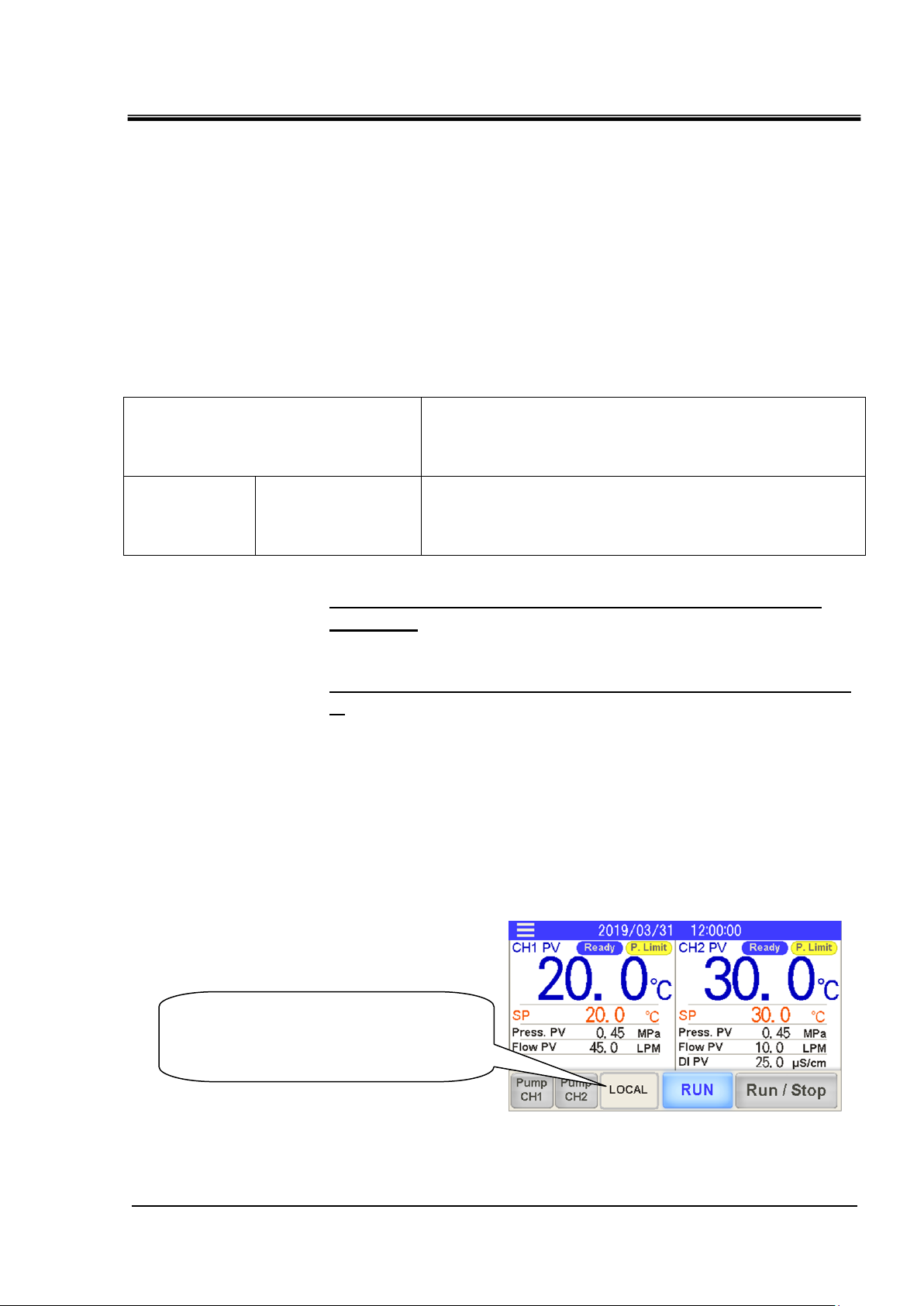
・Displays the current operation mode.
・You can change the operation mode
by pressing it.
The communication of this device consists of contact input/output
communication and analog output communication and serial
communication.
・ The serial communication protocol is a MODBUS communication.
Depending on the customer’s specification, communication can
be changed to contact input/output communication or serial
communication.
Table 1-1 Communication method
HRX-OM-W069
Chapter 1 Read before using
●If using contact input/output communication, refer to
chapter 2.
●If using serial communication MODBUS, refer to chapter
3.
1.1 Operation mode and operation method
LOCAL, DIO and SERIAL are available as the operation modes. Table
1.1-1 explains the operation modes. The default setting is LOCAL.
The operation method depends on the operation mode. Table 1.1-2
shows how the operation mode and method of operation are related.
Operation mode display and setting
HRL Series 1.1 Operation mode and operation method
HRX-OM-W069
1-2
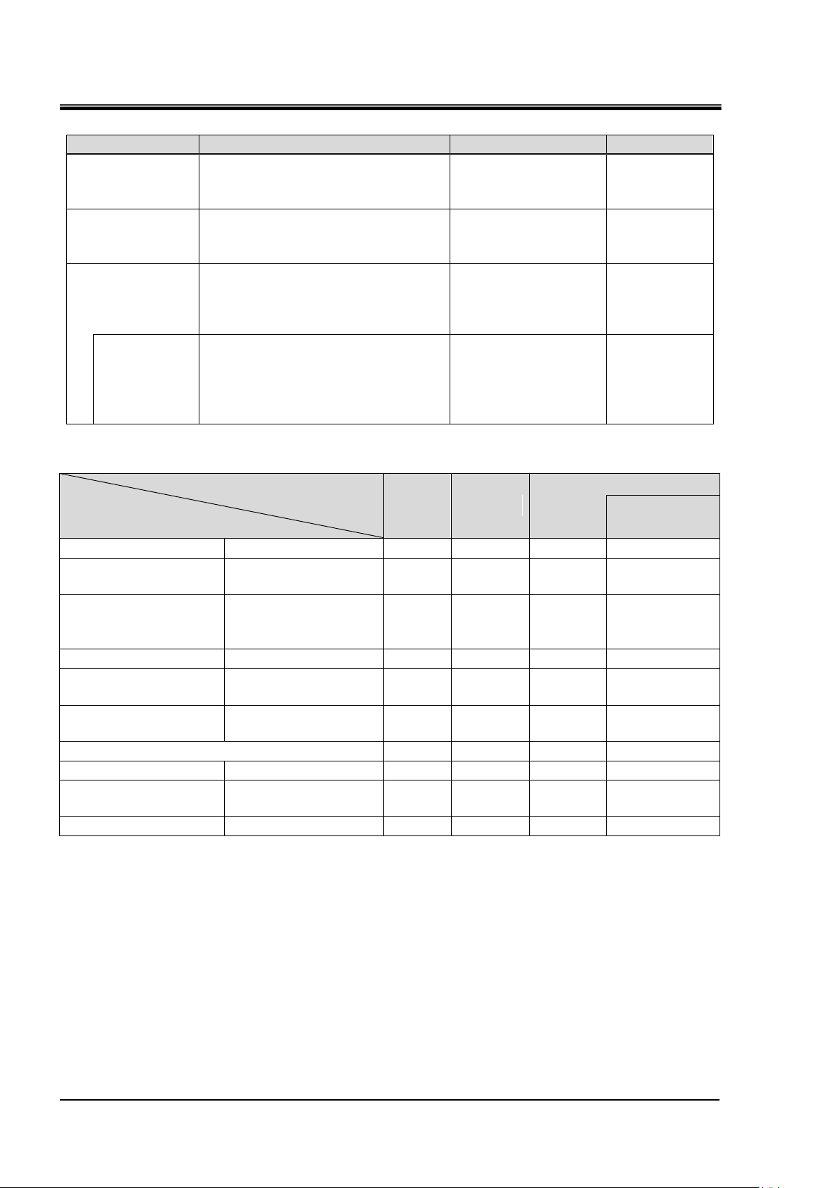
Operation ode
Explanation
Contents
Display
LOCAL
Run / stop and circulating
fluid temperature setting are
possible with the touch panel.
Set the operation
mode to "LOCAL".
To display
the "LOCAL"
DIO
Run / stop by contact input.
Circulating fluid temperature
setting is done at the touch panel.
Set the operation
mode to "DIO".
To display
the "DIO"
SERIAL
Run / stop and circulating
fluid temperature setting are
possible with the serial
communication(RS-232C,RS-485)
Set the operation
mode to "SERIAL".
To display
the "SERIAL"
DIO
Run/Stop
Run / stop by contact input.
Set circulating fluid temperature
by serial communication.
Set to "SERIAL"
mode and set "DIO
Run / Stop" in
"Serial Setting" to
"ON" (enabled).
To display
the "SERIAL
(DIO Run)".
Operation mode
Operation
LOCAL
DIO
SERIAL
DIO
Run/Stop
Touch panel
Run/Stop
○ × ×
×
Touch panel
Circulating fluid
temperature setting
○ ○ ×
×
Touch panel
Settings other than
circulating fluid
temperature setting
○ ○ ○
○
Touch panel
Condition reading
○ ○ ○
○
Contact input/output
communication
Run/Stop
× ○ ×
○
Contact input/output
communication
Condition reading
○
○1 ○ ○1
Reading of the external switch
○ ○ ○
○
Serial communication
Run/Stop
× × ○
×
Serial communication
Circulating fluid
temperature setting
× × ○
○
Serial communication
Condition reading
○ ○ ○
○
Chapter 1 Read before using
Table 1.1-1 Operation modes.
Table 1.1-2 Operation mode and operation
1 Only one external switch can be connected
1.1 Operation mode and operation method
HRL Series
1-3
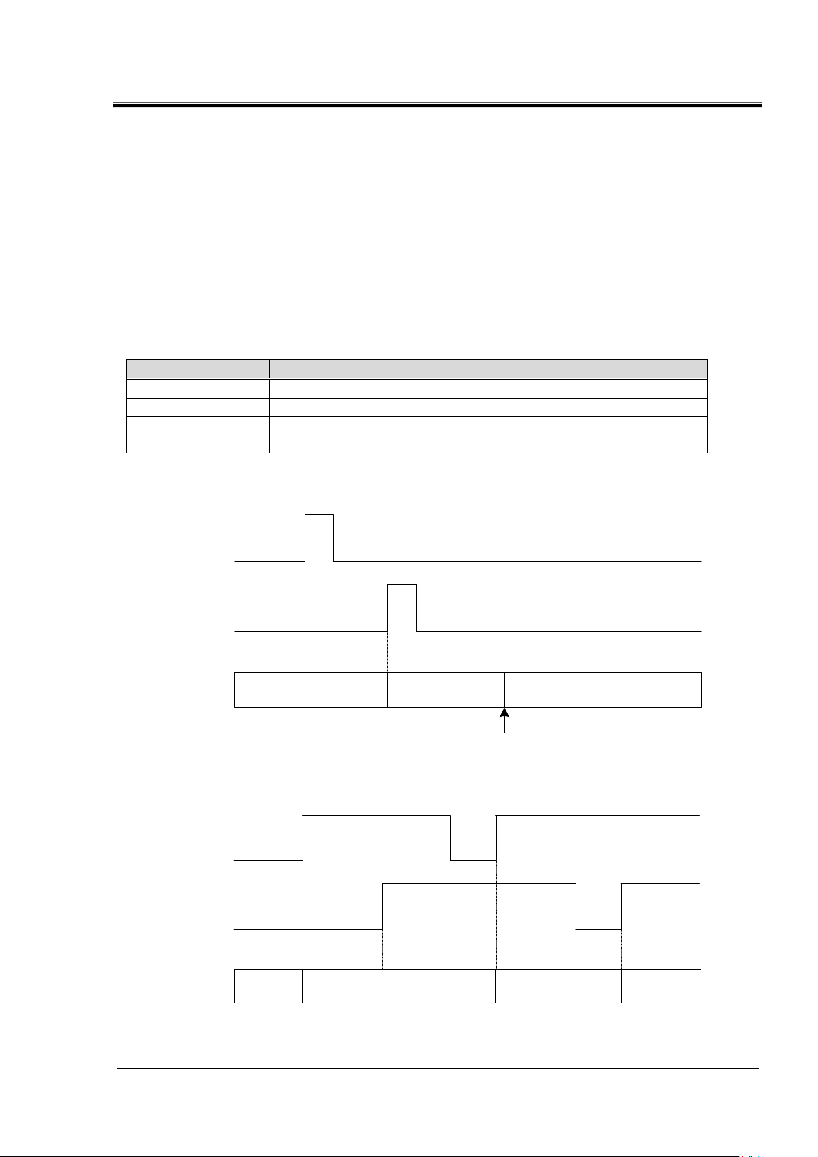
Operation mode
Operation mode change method
LOCAL
None1
DIO
Input the mode request signal (OFF to ON) to contact input 3.
SERIAL
The mode request flag is turned from OFF to ON by serial
communication.2
LOCAL DIO SERIAL LOCAL
Contact input 3
Mode request signal
Serial communication
Mode request flag
Select the LOCAL in the touch panel
Operation
mode
LOCAL DIO SERIAL DIO SERIAL
Contact input 3
Mode request signal
Serial communication
Mode request flag
Operation
mode
HRX-OM-W069
Chapter 1 Read before using
1.2 Change of operation mode
There are the following methods to change the operation mode.
・ Change by touch panel
・ Change by mode request
■About mode request
The mode request, is the ability to change the operation mode by the
contact input or serial communication.
When switching from OFF to ON for both contact input and serial
communication, the mode request becomes effective and the
operation mode changes.
Table 1.2-1 Operation mode change by mode request
1 Change to LOCAL mode is possible only from touch panel operation.
2 When "DIO Run / Stop" is set in advance by the touch panel, run / stop is performed by the contact
input signal.
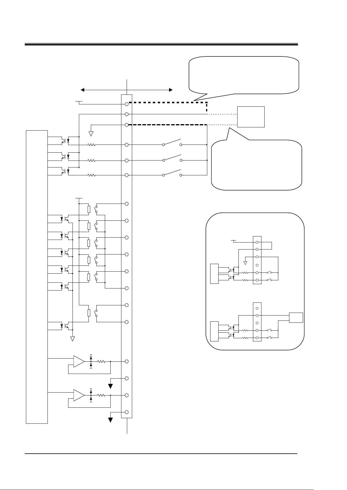
Fig. 1-1 Communication port
Fig.1-2 Mode switching by the mode request (ON state mixed)
HRL Series 1.2 Change of operation mode
HRX-OM-W069
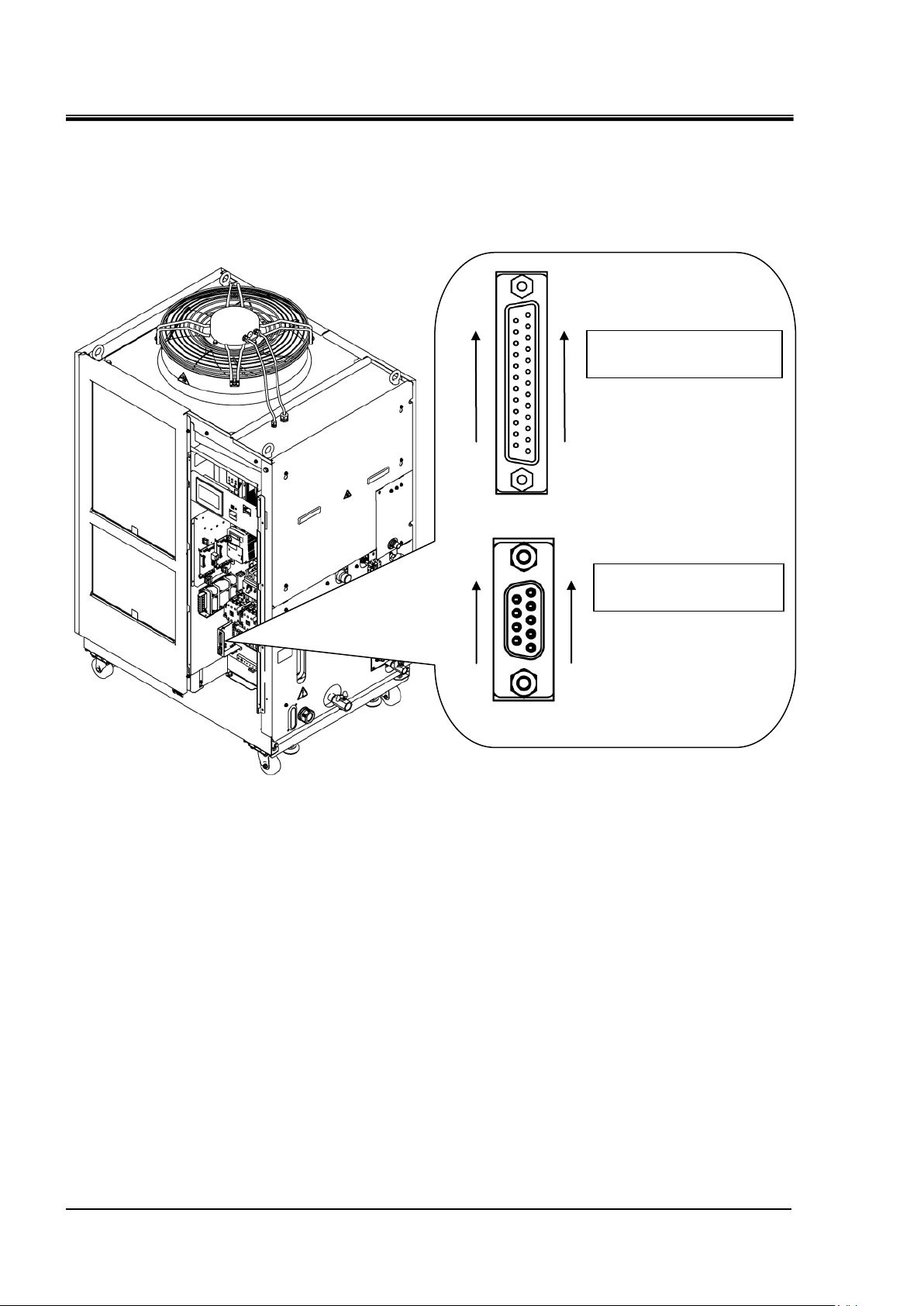
1-4
Contact input / output
signal connector
D sub 25 female pin
(socket) type
Serial communication
connector
D sub 9 female pin
(socket) type
13
1
25
14
5
1
9
6
Chapter 1 Read before using
1.3 Communication port
The communication port In the lower left of the electrical component
box is used for communication.
Fig.1-3 shows the location of the communication port.
Fig.1-3 Communication port
1.3 Communication port
HRL Series
1-5
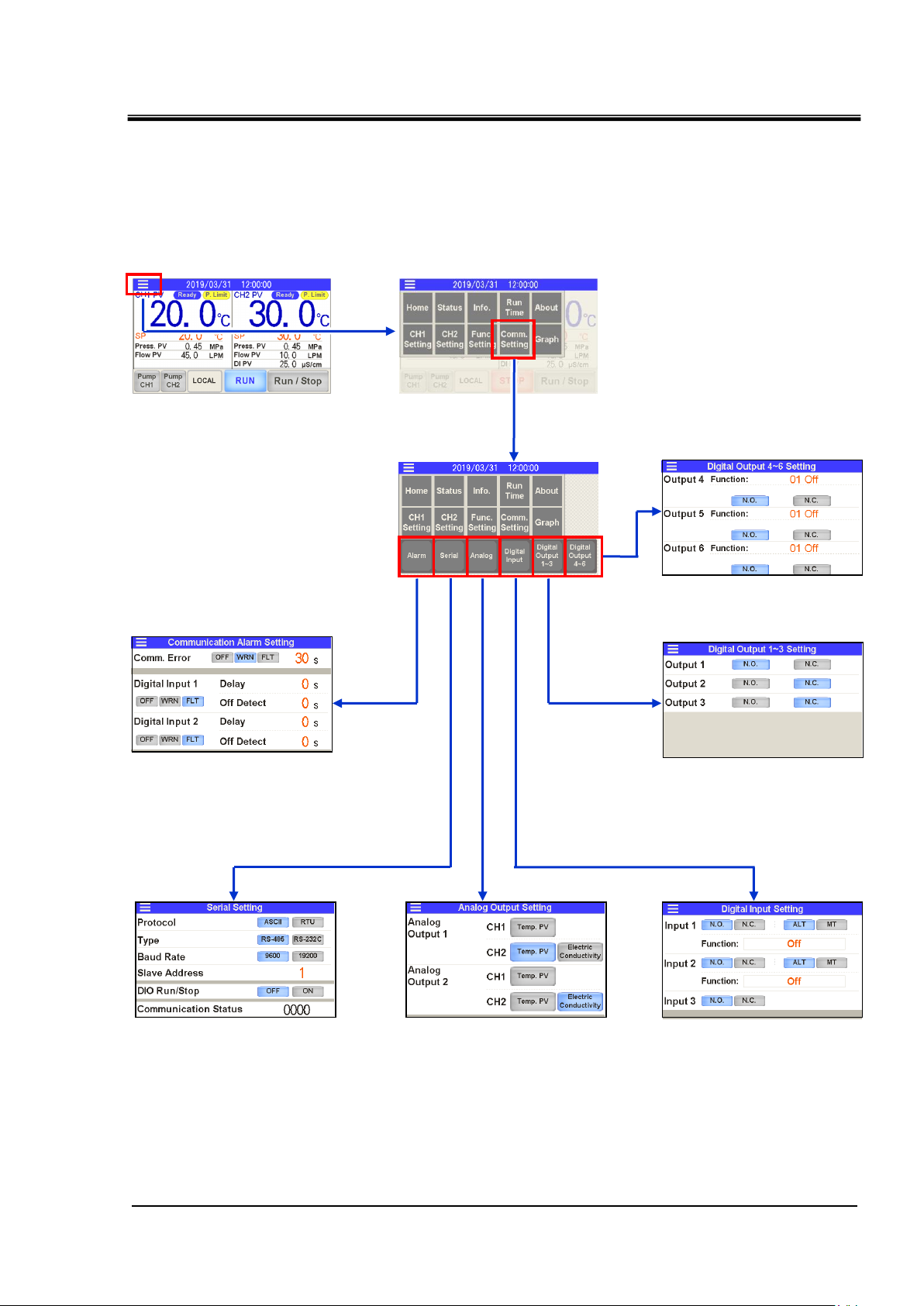
1.4 Touch panel flow
Menu
1. Communication error (AL34)
Detection of contact input signal
Setting for alarm (AL30 and AL31)
3. Analog output setting
4. Setting for contact
input signal 1 to 3
2. Serial communication setting
5. Setting for contact
output signal 1 to 3
6. Setting for contact
output signal 4 to 6
Various screens
Press the [Comm. Setting] on the menu, make the communication
settings from the various setting screens.
Fig.1-4 Communication setting touch panel flow
HRX-OM-W069
Chapter 1 Read before using
HRL Series 1.4 Touch panel flow

HRX-OM-W069
1-6
Chapter 1 Read before using
1.4 Touch panel flow
HRL Series

Chapter 2 Contact input/output communication /Analog output communication
2-1
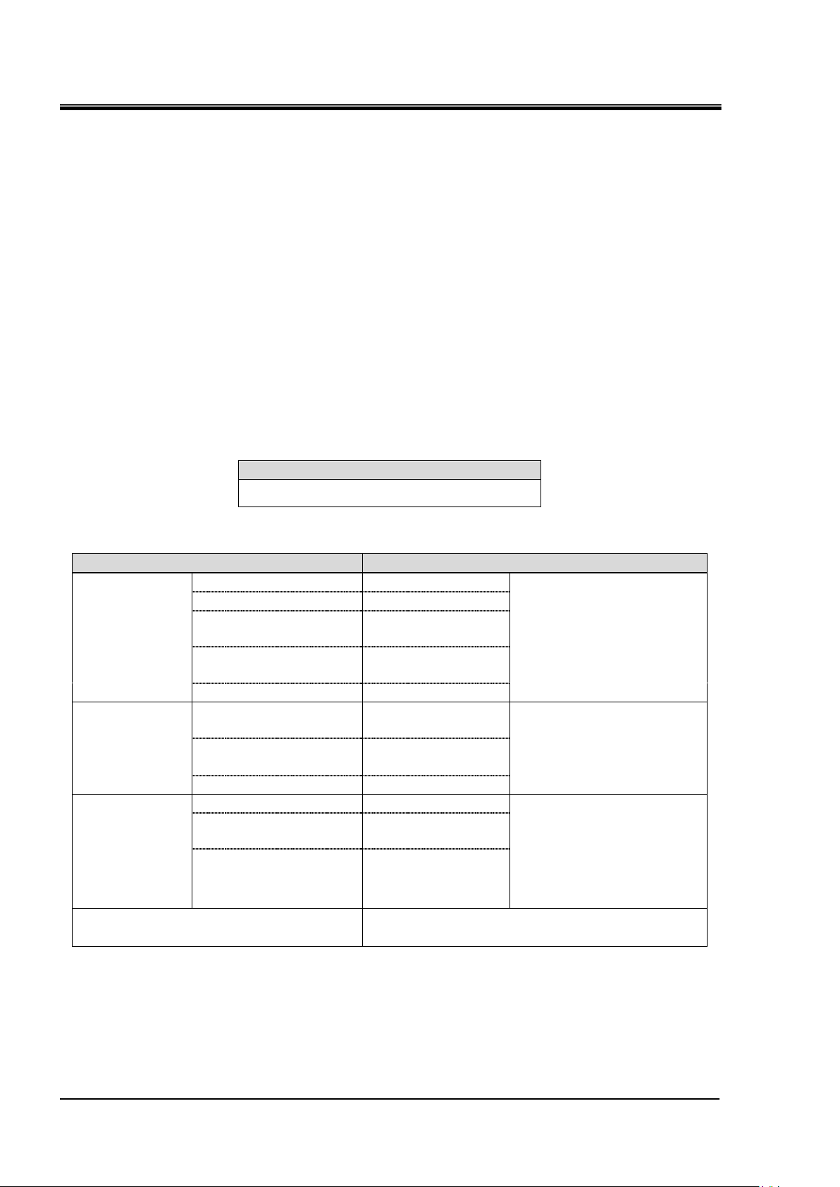
Signal content
Contact input 1
Contact input 2
Contact input 3 Mode request signal only (momentary)
Contact output 1
・Output operation status (RUN / STOP) signal *1
・Selectable contact type (normally open / normally closed)
Contact output 2
・Output the operation stop "FLT" alarm signal *1
・Selectable contact type (normally open / normally closed)
Contact output 3
・Output the continued operation "WRN" alarm signal *1
・Selectable contact type (normally open / normally closed)
Contact output 4
Contact output 5
Contact output 6
Analog output 1
Analog output 2
Signal
Contact input
3pcs.
・Operation / stop signal, Allowed input an external switch signal
・Selectable signal configuration (Alternate/Momentary)
・Selectable contact type (normally open / normally closed)
Contact output
6 pcs.
・Selectable signal content(Refer to “2.4 Contact output signal)
・Selectable contact type (normally open / normally closed)
Analog output
2pcs.
Selectable from the following 3 points
・CH1 Circulating fluid discharge temperature
・CH2 Circulating fluid discharge temperature
・CH2 Circulating fluid electric conductivity
Chapter 2 Contact input/output
communication /Analog
output communication
The device is equipped with a terminal which runs/stops the product. It is also
equipped with a terminal which picks up operation signals, alarm signals and setting
condition.
The device starts contact input/output communication according to the setting of the
operation display panel. Contact input/output communication can be customized by
changing the settings. The contact input / output signals and analog output signals
that this product is equipped with are shown in Table 2-1.
Table 2-1 Contact input / output signal and analog output signal
HRX-OM-W069
1 Signal the contents of the contact output 1 to 3 is a fixed value.
It is not possible to change the content of the signal.
2.1 Precautions for communication
2.1.1 Precautions wiring communication
○Communication wiring
A communication cable that connects the product and customer
system is not included with the product. Please prepare according to
“3.2 Connected explanation”.In order to avoid malfunction, do not
connect to any place other than those shown in “3.2 Connected
explanation”.
HRL Series 2.1 Precautions for communication
HRX-OM-W069
2-2
Connector specification (this product side)
Dsub 25 pin female (socket) type
Item
Specification
Contact
input
signal1,2,3
Insulation system
Photo coupler
・Run/Stop signal
・External switch signal
・Operation mode request
signal
(Contact input 3 fixed)
Rated input voltage
DC24V
Operating voltage
range
DC21.6V to 26.4V
Rated input
current
5mA TYP
Input impedance
4.7kΩ
Contact output
signal
1,2,3,4,5,6
Rated load voltage
AC48V or less /
DC30V or less
・Signal of operating status
・Alarm signal
・TEMP READY signal
etc 2
Maximum load
current
AC/DC
800mA or less 1
Minimum load current
DC5V 10mA
Analog output
signal 1,2
Output voltage range
0V to +10V
・CH1 Circulating fluid
discharge temperature
・CH2 Circulating fluid
discharge temperature
・CH2 Circulating fluid
electric conductivity
Maximum output
current
10mA
Maximum accuracy
±1.0%F.S. or less
DC24V output voltage
DC24V±10% 200mA MAX 1
(It can not be used for inductive load.)
Chapter 2 Contact input/output communication /Analog output communication
○Power supply
To use the power of the product, the total load current must be 200mA
or less.
2.1.2 Precautions after wiring and before communication
○Check or set the Operation mode by the touch panel.
・Operation mode shall be DIO.
You can read also in the other mode, but you can not run / stop if it
is not DIO mode.
2.2 Communication specification
Table 2.2-1 Contact input/output communication connector
Table 2.2-2 Contact input/output/ analog output communication specification
1 : The total load current must be 800 mA or less. To use the power of the device, the total load current
must be 200 mA or less.
2 : Refer to “2.4.2 Contact output signal 4 to 6”.
2.2 Communication specification
HRL Series
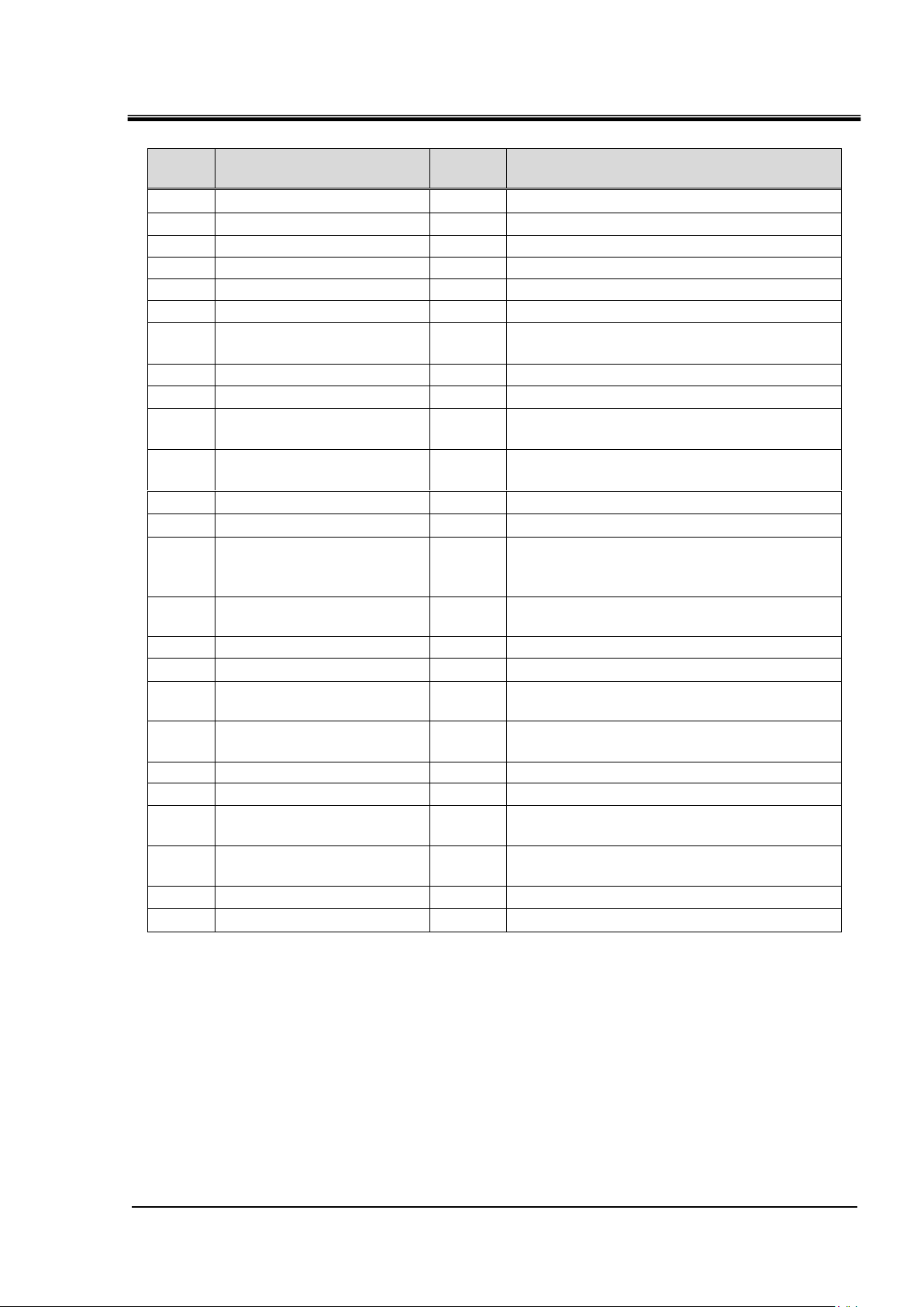
Chapter 2 Contact input/output communication /Analog output communication
2-3
PIN
No.
Item
Division
Contents
1
DC24V output
Output
-
2
DC24V input
Input
-
3
Contact input signal 1
Input
Run/Stop 1
4
Contact input signal 3
Input
Operation mode request signal (fix )2
5
Contact output signal 6
Output
OFF1
6
Contact output signal 1
Output
Run status signal [N.O type](fix)2
7
Contact output signal 3
Output
Operation continuation[WRN]alarm
status signal [N.C. type ](fix)2
8
Contact output signal 5
Output
OFF1
9
None
-
Can not connect
10
Analog output signal 2
Output
CH2 Circulating fluid electric
conductivity signal 1
11
Analog output signal 1
Output
CH2 Circulating fluid discharge
temperature signal 1
12
None
-
Can not connect
13
None
-
Can not connect
14
24 COM output
(Common of contact input
signal)
Output
-
15
Common of contact
output signal 1, 2, 3, 4, 5
Output
-
16
Contact input signal 2
Input
External switch signal 1
17
None
-
Can not connect
18
Common of contact
output signal 6
Output
-
19
Contact output signal 2
Output
Operation stop [FLT] alarm status signal
[N.C. type ](fix)2
20
Contact output signal 4
Output
OFF*1
21
None
-
Can not connect
22
Common of contact
output signal 2
Output
CH2 Circulating fluid electric
conductivity GND
23
Common of contact
output signal 1
Output
CH2 Circulating fluid discharge
temperature GND
24
None
-
Can not connect
25
None
-
Can not connect
Table 2.2-3 Contact input/output communicatin /Analog output pin number
HRX-OM-W069
1 : It is possible to change the setting.
2 : You can not change the setting(“N.O type / N.C. type” can be changed).
HRL Series 2.2 Communication specification
HRX-OM-W069
2-4
Power supply usage example
Analog output 1 : CH2 Circulating fluid discharge temperature
This product side Customer system side
DC24V
+
-
-15V
100Ω
ANALOG COM
24COM
Contact output 1 : Operation status
1
24COM
DC +24V(output)
4.7kΩ
4.7kΩ
4.7kΩ
+15V
+
-
-15V
100Ω
+15V
ANALOG COM
Internal
circuit
14
3
16
4
6
19
7
20
8
15
5
18
11
23
10
22
Contact output 2 : "FLT"
Contact output 3 : "WRN"
Contact output 4 : OFF
Contact output 5 : OFF
(Momentary)
Run/Stop
Operation mode request
[Warning when an alarm occurs OFF]
[Fault when an alarm occurs OFF]
[Operation ON]
Contact output 6 : OFF
2
DC24V
DC +24V(input)
EXT DC24V
EXT 24COM
Power
supply
Analog output 2 : CH2 Circulating fluid electric conductivity
External switch
24COM(output)
Contact output 1-5 common
Contact output 6 common
Analog output1common
Analog output 2 common
When using this product's power supply,
connect pin 1 to pin 2 and the COM side
of each contact input signal to pin 14.
When using a customer's power
supply, connect the 24V DC +
side to pin 2 and the COM side
of each contact input signal to
the customer's power COM.
DC24V
1
14
3
2
1
14
3
2
Power
supply
DC24V
24COM
4
3
4
This product power supply
usage example
Customer power supply usage example
Chapter 2 Contact input/output communication /Analog output communication
2.2 Communication specification
Fig.2-1 Circuit diagram
HRL Series

Chapter 2 Contact input/output communication /Analog output communication
2-5
Setting of contact input signal form
(1)
(2)
(3)
2.3 Contact input signal
There are 3 contact input signals. Two of them can be customized by
the customer.
2.3.1 Setting of contact input signal type and form
The type of contact input signal can be set from the “1.4 Touch panel flow” (Refer
to "4. Contact input signal form" screen).
Following items can be set for contact input signal 1 and 2:
・ Contact type––selects [ N.O. ] (A contact) or [N.C] (B contact)
・ Signal form–––selects [ALT] (alternate) or [MT] (momentary)
・ Signal type–––selects “OFF” (disabled), “external switch” (external switch
signal) or “run/stop” (run/stop) signal., Run (run) signal, Stop
(stop)signal
HRX-OM-W069
HRL Series 2.3 Contact input signal

HRX-OM-W069
2-6
No.
Indication
Item
Setting and selection
(1)
Input 1
Contact input
signal 1
Contact
type
1
A contact (normally open)
B contact
(normally closed)
Signal
form
1
Alternate
Momentary
Signal
type
[Off]
Disabled
[External Switch]
External switch signal
[Run/Stop] 1
Run/stop signal
[Run] 2
Run signal
(2)
Input 2
Contact input
signal 2
Contact
type
1
A contact (normally open)
B contact
(normally closed)
Signal
form
1
Alternate
Momentary
Signal
type
[Off]
Disabled
[External Switch] 1
External switch signal
[Run/Stop]
Run/stop signal
[Stop] 2
Stop signal
(3)
Input 3
Contact input
signal 3 3
Contact
type
1
A contact (normally open)
B contact
(normally closed)
Chapter 2 Contact input/output communication /Analog output communication
Table 2.3-1 Setting of contact input signal form
1 : By default.
2 : This setting assigns “run” signal to “contact input 1” and “stop” signal to “contact input 2”.
3 : The signal form of contact input 3 is “momentary”.
2.3 Contact input signal
HRL Series

2-7
OFF
ON
Run
Stop
Product condition
Run/stop signal
(Alternate)
O
FF
ON
Run
Stop
Product condition
Run/stop signal
(Momentary)
O
FF
ON
Run
Stop
Product condition
Run signal
O
FF
ON
Stop signal
②
①
③
Chapter 2 Contact input/output communication /Analog output communication
2.3.2 Run/stop・Run・Stop・External switch signal
1) Run/stop signal (Signal type: Alternate)
The product keeps operating while the input signal from the customer is ON.
2) Run/stop signal (Signal type: Momentary)
The state changes when the input signal from the customer goes ON. This signal
operates while the product is stopped, and stops while the product is being operated.
3) Run signal (Signal type: Alternate) /Stop signal (Signal type:Alternate)
Digital input signal 1 is for Run signal(Signal type:Alternate), digital input signal 2 is
for stop signal(Signal type: Alternate). Stop signal becomes valid when both signals are
turned ON.
(1) The product starts operation when the contact input signal 1 is turned ON.
(2) The product stops operation when the contact input signal 2 is turned ON.
(3) The product starts operation because the contact input signal 1 is turned ON
although the contact input signal 2 is OFF.
HRX-OM-W069
HRL Series 2.3 Contact input signal
 Loading...