

Page 1
1
Getting Started
HF-150
COMMUNICATIONS RECEIVER
OPERATING
MANUAL
South Midlands
Communications Ltd
Page 2
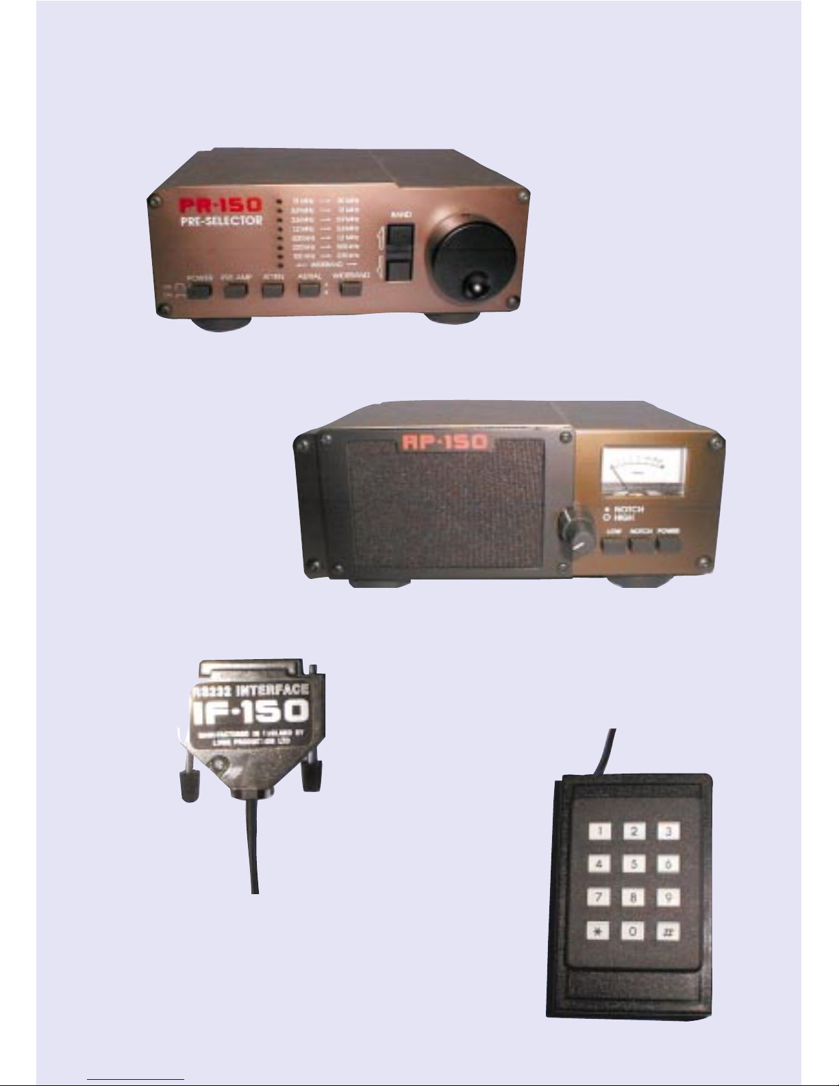
PR-150
For add selectivity
and rejection of
unwanted signals
AP-150
Digital Audio
Processor for
enhanced audio
output
IF-150
Computer RS232
Serial interface for
ease of control
and auto
frequency
selection
KPAD-2
Keypad for ease of
remote access to
frequency and
mode selection
HF-150 ADD ON ACCESSORIES
Page 3

HF-150 - Users Manual
3
Getting Started
Contents
Introduction . . . . . . . . . . . . . . . . . . . .4
Getting started
Aerials . . . . . . . . . . . . . . . . . .5
Active Antenna . . . . . . . . . . .7
Connections . . . . . . . . . . . . .8
Types of signal . . . . . . . . . .10
Controls
Front Panel . . . . . . . . . . . . .14
Rear Panel . . . . . . . . . . . . . .16
Operating the HF-150
Volume . . . . . . . . . . . . . . . .18
Modes . . . . . . . . . . . . . . . . .18
Tuning . . . . . . . . . . . . . . . . .19
Keypad . . . . . . . . . . . . . . . .21
Aerial switch . . . . . . . . . . . .23
Memories . . . . . . . . . . . . . .24
Accessory kit . . . . . . . . . . . . . . . . . .25
Care of your receiver . . . . . . . . . . . .26
General notes . . . . . . . . . . . . . . . . . .27
Technical information . . . . . . . . . . .28
(c) 1999 South Midlands Communications Ltd
Page 4

HF-150 - Users Manual
4
Getting Started
The term "Communications Receiver" was originally used in its quite literal
sense to describe a radio receiver which was part of a point to point
communications link. These radio links were normally manned by trained
operators, and Morse Code was the usual method of transmitting information.
Because of the specialist nature of the system and the fact that the operators
were technically trained the communications receiver itself was quite often a
complex piece of equipment.
Over the past twenty or so years, a marked change has taken place in short
wave spectrum occupancy and there has been a considerable increase in
broadcasting, air traffic control, news agency transmissions and so on. The
interest in listening generated by this spread of activity has led to a demand
amongst the general public for receivers which will enable them to keep in
touch with world affairs by short wave radio.
Clearly, these users of receivers are more interested in listening than in the
technicalities of operating the equipment and this in turn has resulted in the
introduction of simpler receivers. However, simplicity of operation has often
been accomplished by a compromise in actual performance, and the results
obtained from some of these simple receivers have been quite disappointing.
As our founder once remarked, "Some receivers are rather like a chocolate
eclair; Wonderful to behold but containing little of substance."
The design and development of the HF-150 was based on
straightforward objectives:* To obtain sufficient RF performance for the receiver to operate in
crowded short wave bands with many strong signals.
* To combine complete control of a necessarily complex piece of
equipment with easy operation for the user.
* To achieve both the previous objectives within a compact, portable
package at a reasonable price.
We believe that these stated goals have been reached, and that the HF150 receiver represents a truly new approach to meeting the demands of the
serious short wave listener.
Page 5

HF-150 - Users Manual
5
Getting Started
Aerials and Earths.
Operating the HF-150 is described in the next two sections of this manual, but
you may well ask "What is a suitable aerial?" The receiver has been designed
to work well with a simple long wire aerial, about 10 to 30 metres long. This will
provide good results on most frequencies covered by the set, but if your
interest is in a particular band, such as the 49 metre broadcast band, you may
wish to consider a dipole aerial tuned to that frequency. Do not be dazzled by
the idea of putting up the longest wire in the whole world. This will bring you to
grief, because you will probably overload the input stages of the receiver with
signals from strong broadcast transmitters, with a resultant increase in
background noise.
Where space is at a premium a short wire aerial (a few metres long, maybe
indoors) or a whip aerial can be used. The HF-150 includes a whip antenna
input circuit which optimises its performance with short aerials or in weak signal
areas. However reception, particularly of lower frequencies (long and medium
wave), will be compromised by a short aerial and the receiver will be more
susceptible to locally generated interference.
A good aerial deserves a good earth connection and a ground system
specifically for the receiver is always an advantage. This can be made fairly
simply by driving a metal post into the ground to a depth of about 1 metre and
connecting it to the black ground terminal on the rear panel of the receiver. With
the exception of the 110V model, the mains power supply for the HF-150
provides an earth connection from the receiver to the mains earth system. This
is often adequate for most locations, but in some situations can result in
excessive interference from other mains appliances, which a separate earth
system would avoid.
Long wire aerials should connect to the red terminal on the rear panel of the
HF-150, whereas whips or short wire aerials should connect to the centre of the
co-axial connector - a 4mm plug can be used to connect wires into this - and
the antenna select switch set to the WHIP position. Any aerial systems that
connect to the receiver by co-axial cable (active aerials and dipoles) should use
the co-axial connector with the selector switch in the NORM position.
Page 6
HF-150 - Users Manual
6
Getting Started
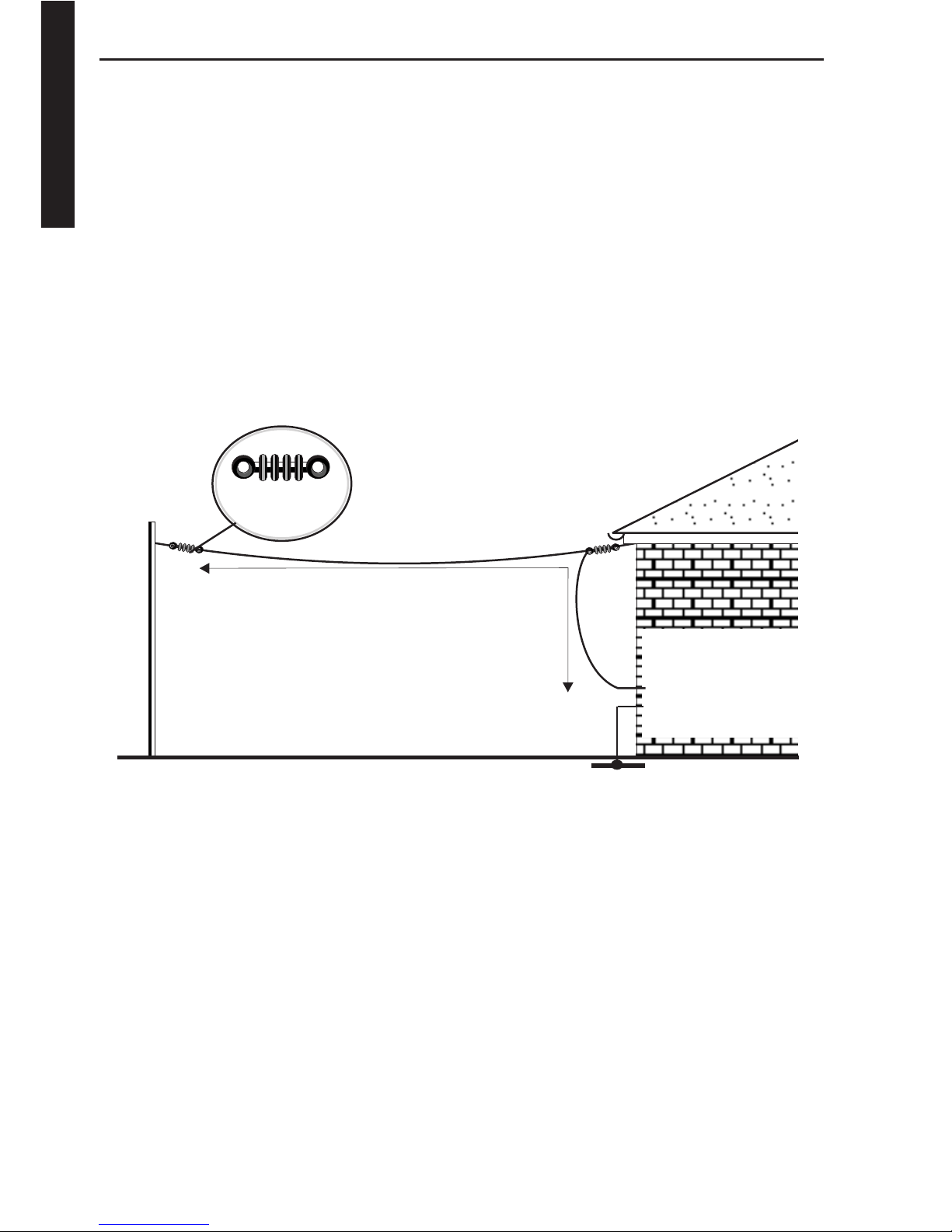
The Long wire Aerial.
This is the simplest type of outdoor aerial system, and is very effective for
general short-wave listening. It consists of a single, insulated wire erected with
a horizontal top section and a down lead from one end going to the receiver's
wire aerial input terminal. The wire should be erected as high as possible, and
as far away as possible from other structures or overhead power lines. It can
often be suspended between two buildings or between a building and a tree.
Insulators should be used as shown, and the lead in wire should also be
insulated. The drawing shows a long wire in the form of an "Inverted L," but
many other configurations can be used, such as a slanting wire leading directly
to the receiver.
Other Aerials.
There are several ready-made vertical aerial systems on the market, and they
will provide an easy to erect system occupying very little ground area. They are
normally designed to work over quite a narrow frequency range (typically
amateur radio bands), and for general listening a simple wire will often give
better results.
Active aerials attempt to overcome the problems of very short aerials by placing
a high-impedance amplifier between the antenna and the receiver. The
amplifier must be near to the aerial, so often power is fed to it along the co-axial
cable connecting it to the receiver. The active aerial is very compact, often little
more than a metre long, but a poorly designed active aerial can badly
compromise the receivers performance due to the amplifier overloading in the
presence of many strong broadcast signals.
SMC P2
INSULATORS
LENGTH = 10 to 30m
AERIAL GROUND
RECEIVER
CONNECTIONS
TO AERIAL SOCKET
TO EARTH
Page 7

HF-150 - Users Manual
7
Getting Started
HF-150 MARINE RADIO
IMPORTANT
If you have purchased the Marine Radio version of the HF-150 you should be
aware of the following.
The HF-150 is sent out for normal passive aerial use.
You can use this radio with an active aerial, which will require a 12V DC supply
at the aerial socket.
To make the socket active.
1 Remove the four base fixing screws
2 Remove the bottom cover
3 Connect jumper to bridge the connector at the rear of the PCB.
WARNING: THIS WILL SUPPLY +12VDC TO THE AERIAL SOCKET AND THE
JUMPER SHOULD BE REMOVED FOR NORMAL PASSIVE AERIAL USE
We strongly advise you to label the aerial socket clearly to inform users that
12VDC is present at this outlet.
South Midlands Communications Ltd will accept no responsibility or liabity for
the incorrect use of this feature.
If in doubt consult your dealer.
Suitable Active Aerial
The AA-150M optional accessory is a high performance active antenna which
has been specially designed for the marine version of the HF-150(M).
This aerial has been carefully optimised to match the high performance of the
HF-150M to prevent an overload of signal.
The modification details above will need to be set for use with this aerial.
Page 8

HF-150 - Users Manual
8
Getting Started
Connections.
Power Supply.
The HF-150 receiver can operate from its internal batteries or from an external
DC supply of between 10 and 15 volts. The absolute maximum supply is 16
volts, and if this is exceeded damage may occur to the receiver. The supply
polarity is negative ground only , and although reverse polarity protection is built
in it is wise to ensure that any supply is correctly connected. Be sure that the
receiver power switch is OFF before plugging in or unplugging the power
connector.
In most countries, the HF-150 will be supplied with a small 12 volt regulated
power unit which is designed to operate from the local mains power.
Remember that this supply will be operating all the time that it is connected to
the mains outlet, and it is a wise safety precaution to disconnect it from the
mains supply when the receiver is not in use.
The HF-150M marine receiver is supplied with a 12 volt lead only.
In the United Kingdom the power supply is fitted with a three-core mains lead,
and the earth connection (yellow/green) is connected to the negative (ground)
terminal of the receiver. This provides a reasonable earth connection for the
receiver, but in some cases, where the mains-born interference is prominent, it
will be necessary to provide the receiver with a good RF earth, either in addition
to the mains earth or in some cases instead of it. If the receiver is used with any
other mains power supply it should be able to comply with BSI standards
relating to Class 2 insulation.
Either alkaline-manganese batteries or rechargeable nickel-cadmium batteries
can be fitted to the receiver if it is to be used away from a source of power.
Rechargeable batteries will charge within the set if it is connected to a 12 volt
power source and switched off. For this reason we recommend that nonrechargeable ones are removed from the set if it is used for more than a few
hours on an external supply.
Rechargeable batteries will run the set for three to four hours on a full charge,
and require about 16 hours to charge fully from a 12 volt supply. Charging time
can be longer that this without damaging batteries.
Page 9

HF-150 - Users Manual
9
Getting Started
External Loudspeaker.
A small internal loudspeaker is provided in the HF-150 so that it is self
contained, but although it can provide reasonable all round audio quality,
clearly in the limited space available compromise has to be made. You will find
that if the volume control is set to a high level there may be some audio
feedback caused by vibration induced by the internal loudspeaker. If it is
necessary to operate the receiver at high audio levels, or you want better
quality reproduction the use of an external loudspeaker is recommended.
Because the HF-150 is capable of giving a high quality audio signal, we
suggest you use a good external loudspeaker, a small bookshelf type Hi-Fi unit
is satisfactory. We can provide a suitable unit as an optional accessory with the
correct connecting lead for the HF-150. Any external loudspeaker should have
an impedance of 4 ohms or greater.
Record Output.
Many keen listeners like to tape record any interesting stations they hear, and
a low level audio output has been provided for this purpose.
The REC OUT socket accepts a 3.5mm mono jack plug and provides a level
suitable for feeding into the line input of most tape recorders or amplifier
systems. An attenuating resistor should be added in the lead if feeding directly
into the microphone input of a cassette recorder. The output level at this socket
is not affected by the volume control, so that the loudspeaker can be used to
monitor whilst recording.
The record output can also be used for driving most types of receiver ancillary
equipment such as RTTY, facsimile or Morse decoders. The output level is
about 200m V from a source impedance of 5k ohms.
Page 10

HF-150 - Users Manual
10
Getting Started
Types of Signal.
The HF-150 is equipped to receive most types of transmission likely to be found
within its tuning range, and although most users will be familiar with these, here
are some brief notes on this topic that may be useful to beginners.
AM (Amplitude Modulation).
This was the earliest method used of audio modulation of an RF carrier wave,
and is still almost universally used for long, medium and short wave
broadcasting. An AM signal is fairly easy to tune in, and given a reasonable
signal strength, the receiver may not need to be spot on in frequency. However
when conditions are poor, AM can be difficult to resolve - one particular
problem is frequency selective fading and this is discussed later.
AM Selectivity.
A radio signal occupies a certain portion of the radio spectrum which is known
as its bandwidth. The bandwidth of an AM signal is twice its highest modulation
frequency , and because of this broadcasters are restricted to transmitting audio
frequencies below 5kHz so that they do not occupy too much spectrum. In the
long and medium wave broadcast bands, station frequencies are separated by
9kHz (10kHz in the USA) so there is little or no overlap of adjacent signal
bandwidths. In the short wave bands however, the stations use a nominal 5kHz
spacing, and some broadcasters do not abide by any rules at all, so there is
considerable signal overlap.
The HF-150 is provided with two different AM modes with different filter
bandwidths because of this very problem. If you are receiving a strong signal
in a clear part of the radio spectrum then you can use the standard AM mode
with a 7kHz filter and obtain the best fidelity. The stronger and closer adjacent
stations are, the narrower the filter you will need, and the more muffled the
sound will be because high frequencies are removed. The narrow AM mode
uses a 2.5kHz filter and is necessary in severe conditions, but it is really only
suitable for speech reproduction. When AM mode is chosen you may find that
reception of a station is improved by tuning the receiver slightly above or below
its stated carrier frequency. This is quite a useful technique if there is a strong
adjacent signal that you don't want. As long as the carrier signal is within the
receiver's filter then all will be well, but if you tune too far or select a narrower
filter then the signal will become distorted.
Page 11

HF-150 - Users Manual
11
Getting Started
SSB (Single Sideband).
An AM signal can be considered as a carrier wave combined with two identical
sidebands which contain the modulating audio signal. It is possible to remove
one of the sidebands without losing any vital information, and immediately
halve the bandwidth occupied by the signal. In practice the carrier wave is also
removed (or partially suppressed) to improve transmission efficiency, and the
result is a single sideband transmission.
SSB transmissions are used extensively for voice communication, particularly
to aircraft and shipping, and also by radio amateurs. It is possible to use either
of the two initial sidebands of a signal, so there are two distinct types of SSB
transmission; Upper Sideband (USB) where the sideband frequency is above
the carrier frequency, and Lower Sideband (LSB) where it is below. Nearly all
commercial transmissions are USB, as are amateur transmissions at
frequencies above 10MHz. At frequencies below 10MHz radio amateurs use
LSB by convention.
To receive an SSB transmission, the receiver must reinsert the missing carrier
signal. If this is not done the signal will sound just like Donald Duck - try
listening to an SSB signal in AM mode for this effect. For correct reception the
receiver should be tuned exactly to the carrier frequency, but for speech an
error of 50Hz either way will not be serious. The HF-150 has a very slow tune
rate on its SSB modes to facilitate accurate tuning, but you will need a steady
hand. The pitch of the received voice will change as you tune through the
signal, buy only at one tuning position will it sound like a natural voice. A
2.5kHz bandwidth filter will just accommodate the audio frequencies used for
voice transmission, and this is the filter used for SSB reception.
CW (Continuous Wave, i.e. Morse).
Morse code is usually transmitted by interrupting a single carrier wave, and it
occupies a very narrow bandwidth. In terms of ability to get a message through
under difficult propagation conditions Morse code is one of the most efficient
method, although modern error-correcting digital data systems are also very
good. CW signals are received in the same way as SSB signals, with the carrier
inserted in the receiver producing a beat note with the incoming signal, and
either the LSB or USB modes can be used. Often the one chosen is a matter of
operator preference, or one which best rejects any interfering signals.
Page 12

HF-150 - Users Manual
12
Getting Started
RTTY (Radio Teletype).
The method of sending teleprinter messages by HF radio link is to use
two closely spaced tone signals, transmitting one or the other to send binary
data. Each teleprinter character is encoded into a different sequence of tones
which are transmitted in a bewildering combination of different speeds, tone
shifts, and code types. RTTY signals are tuned in SSB mode on a receiver, but
require a special terminal unit to decode and display the actual text.
FAX (Facsimile).
Pictorial information (often meteorological data) is transmitted over HF
radio links for reception by shipping. As with RTTY, a special facsimile decoder
and display or printer is required for its reception. Several home computers
support software packages for decoding FAX and RTTY signals.
FM (Frequency Modulation).
FM transmissions in the HF spectrum are usually limited to the 27MHz
Citizens Band and the 28MHz amateur band. The HF-150 does not offer an FM
mode to directly receive these signals, but it is usually possible to resolve them
in AM mode with the receiver off-tuned by some 3kHz above or below the
transmission frequency. This is technically known as 'filter slope detection'.
AM Propagation and Fading.
During AM signal reception it is possible to experience severe fading problems,
particularly after nightfall. This is mainly due to the signal reaching the receiver
by several different paths from the transmitter, and it is most common after dark
because this is when the ionosphere reflects most HF radio signals. Fading
occurs when the signals arrive at the receiver in antiphase (having travelled
different distances) and then cancel each other out. This will only occur at a few
specific frequencies at any one instant, hence the term frequency selective
fading.
If a selective fade reduces the carrier level of an AM signal, but leaves the
sideband levels unaltered, a receiver with a conventional AM detector will not
be able to correctly reproduce the signal, and the output will be distorted.
There are two techniques that can be used to improve the situation; ECSS, and
Synchronous (or Phase-Locked) AM detection.
Page 13

HF-150 - Users Manual
13
Getting Started
ECSS (Exalted Carrier, Selectable Sideband).
The ECSS technique makes use of the fact that with a good, selective receiver,
capable of resolving SSB, an AM signal can be passed through the SSB filter
which is only wide enough to allow one sideband through. The filter must
attenuate the carrier signal by at least 20dB for this technique to work with any
success.
The receiver can be used in the SSB mode with the incoming AM carrier tuned
to zero beat, and the accompanying sideband treated as a true SSB signal.
Either the upper or lower sideband can be selected using either USB or LSB
mode, so interfering stations can often be eliminated. The improvement in
intelligibility is often dramatic, and it is well worth trying out ECSS and
developing the ability to use it. The HF-150 when used with its USB or LSB
modes is ideally suited to ECSS reception.
AMS (Synchronous AM)
The difficulty in receiving music signals with the ECSS method is that it is very
difficult to match the receivers injected carrier exactly with the frequency of the
incoming carrier. Any difference results in a frequency shift of the audio signal,
and the consequent loss of harmonic relationships.
The synchronous AM detector in the HF-150 uses a narrow deviation phaselocked oscillator to replace the incoming AM carrier. When locked, this
oscillator is at exactly the same frequency as the carrier signal, and does not
have to rely on absolute receiver tuning accuracy. Incoming carrier level
changes make no difference to the signal detection provided that there is some
carrier for the oscillator to lock on to.
A total of four filter arrangements are available on the HF-150 in synchronous
AM mode: - upper sideband only, lower sideband only, both sidebands (for
better resistance to fading if there are no interfering signals) and a special "HiFi" mode which gives extended frequency response and very low distortion for
listening to clear, strong stations.
Page 14

HF-150 - Users Manual
14
Controls
Front Panel Controls.
1) Memory mode flag: This segment of the display is shown when the
receiver is in memory mode. The keypad and tuning knob select memory
numbers, and the three control buttons operate as MEMORY, RECALL and
STORE.
2) Frequency display: The 5-digit liquid crystal display normally shows
the receiver's tuned frequency, with a decimal point in between megahertz and
kilohertz sections. At frequencies below 1.7MHz, (i.e. medium and long
wavebands) the display shows kilohertz with no decimal point. Additionally the
display is used to indicate mode and memory number when appropriate
control buttons are pressed.
3) Tuning knob: For tuning the receiver and selecting memories. The rate
of tuning is altered according to the receiver's mode and the speed of rotation
of the tuning knob. Memory numbers are changed by turning the tuning knob
when the receiver is in memory mode.
12.095
COMMUNICATIONS
RECEIVER
VOLUME
ON OFF
PHONES
MEM
MEM MODE
FAST
RCL
STO
2
87654
31
HF-150
Page 15

HF-150 - Users Manual
15
Controls
4) Volume control: Combined with the on/off switch, the volume control
operates for the internal and external loudspeakers and the headphone output.
The record out jack is unaffected by the volume setting. The on/off switch
controls receiver power and battery charging if NiCd batteries are fitted.
5) Headphone jack: An output for use with personal headphones - the
receiver's internal speaker is disconnected when headphones are plugged in.
A 6.3mm mono or stereo plug is suitable for the headphone output, and
'phones fitted with a 3.5mm plug can be used with a suitable adapter. Stereo
headphones will operate in mono.
6) Memory button: Pressing the MEM button changes the receiver
between memory and tuning modes. In memory mode the memory flag (1) is
shown and the tuning knob and keypad select memory numbers. When in
memory mode, pressing MEM, RCL or STO will revert to tuning mode.
7) Mode button: The MODE button operates when the receiver is in tuning
mode, and allows selection of the type of reception. The display shows a
mnemonic representing each mode, and the other two buttons can be used to
step forwards or backwards through the eight available modes. See page 15
"Modes". Reception changes as soon as a new mode is selected. The display
will revert to frequency when MODE is pressed a second time, or after about 7
seconds without any buttons being pressed, or if the tuning knob is rotated.
8) Fast tune button: If the receiver is in tuning mode, pressing the FAST
button speeds up the tuning rate of the main tuning knob. The two right-hand
display digits are blanked, and the display is altered in 100kHz steps. The
receiver is tuned to the newly selected frequency when the FAST button is
pressed again.
Page 16

HF-150 - Users Manual
16
Controls
Rear Panel Controls and Connections.
9) Battery holders: The HF-150 needs a total of eight AA size batteries to
operate - 4 cells in each of the two battery holders. The Battery drawers are
released by squeezing together the lugs on either side of the holder. When
replacing a drawer make sure that it is pressed fully in so that the cells are
suitable, but all eight cells must be of the same type. Standard zinc/carbon
cells are not recommended because of the risk of leakage.
Nickel/cadmium cells will recharge in the receiver provided that it is connected
to a 12volt supply and the volume/power switch is in the OFF position. Nonrechargeable cells should be removed from the receiver if it is connected to an
external supply for more than a few hours.
10) Keypad jack: For connection of the optional keypad unit, allowing
direct entry of frequencies and memory numbers.
11) Coaxial/Whip aerial connection: This SO-239 type connector provides
the receiver input from aerials terminated with coaxial cable (nominally 50
ohms impedance) or for the whip aerial supplied in the accessory kit. The
select switch (12) determines the function of this socket.
HF-150
131211
9
10
14 15 16 17
Page 17

HF-150 - Users Manual
17
Controls
12) Aerial select switch: This three-position switch controls the operation of
the whip aerial amplifier and the RF attenuator. In the WHIP position the SO-239
socket (11) is intended for a whip aerial or a short wire (just a few metres) and
the spring terminal (13) is disconnected. In the NORM and ATTEN positions
both aerial input are operative, with signal strengths reaching the receiver
being reduced in the ATTEN position.
13) Wire aerial connection: The red spring terminal is for connection of
long wire aerials and has a nominal impedance of 600 ohms. This input is
disconnected from the receiver when the aerial select switch (12) is in the WHIP
position.
14) Ground connection: The black spring terminal is connected to the case
of the receiver and serves as the connection to an RF earth if this is provided.
See page 3 "Aerials and Earths".
15) Record output jack: A fixed level audio signal is available from this
socket that is unaffected by the volume control setting. The level (about
200mV) is suitable for feeding into the line input of most tape recorders and for
driving FAX, RTTY, etc decoders. If the signal has to be fed into the microphone
input of a tape recorder (in the absence of a line input) then a series resistor
should be inserted in the connection to reduce the signal level.
16) External loudspeaker jack: For connection of an external loudspeaker
of 4 to 8 ohms impedance. Inserting a plug into this jack will disconnect the
internal loudspeaker, and this output is disconnected by insertion of a plug into
the front-panel headphone jack.
17) Power input connection: An external DC power supply is connected
here if the set is not to run on its internal batteries. If you are not using the
supplied mains adapter then check that the supply polarity is correct (positiveinner, negative-outer) and that the voltage is between 10 and 15 volts. Current
requirement is about 120mA rising to 300mA at high volume settings.
Page 18

HF-150 - Users Manual
18
Controls
Operating the Receiver.
Volume/Power.
The volume control affects the level of the sound from the loudspeaker or fed
to the headphones. The signal from the record out socket on the rear of the
receiver is not altered. It also functions as a power switch, and turning it fully
counter-clockwise will turn the receiver off. If you are running the receiver from
its mains adapter then the adapter will still be powered even if the receiver is
turned off, and you should switch off or unplug the adapter when not in use.
If rechargeable batteries are fitted to the HF-150 then they will charge if power
is supplied to the receiver when it is switched off. The batteries will fully charge
in about 16 hours from a completely discharged condition. A limited amount of
over-charging will not harm the batteries, but you should avoid charging for
periods longer than 3 days. When the receiver is switched on, a small tricklecharge is supplied to the batteries which will maintain a full charge against
gradual leakage.
When running the receiver from batteries, a message LoPr (low power) will be
shown when the battery voltage falls below a usable level. The tuning and
push-button controls will stop operating but the receiver may still work for a few
minutes. Replace the batteries or run the receiver from an external supply to
restore normal operation. It is common for the low power message to display
momentarily when the receiver is switched off.
Modes.
There are three types of reception available on the HF-150: - Single sideband,
AM and Synchronous AM (AMS). The eight modes selectable on the receiver
choose various filter combinations within these three types. Mode selection is
made by pressing the MODE button on the front panel of the receiver and then
using the other two buttons to step backwards or forwards through a choice of
modes, shown by mnemonics on the display . When a mode has been selected,
it will remain displayed, and can be further changed, for about 7 seconds
before the display reverts to frequency. Pressing the MODE button or turning
the tuning knob during this period will immediately cause the display to revert
to frequency. The mode selection sequence is shown over the page.
Page 19

HF-150 - Users Manual
19
Operation
Type Display Mode Filter Bandwidth
SSB LSb Lower sideband 2.5kHz
Usb Upper sideband 2.5kHz
AM A AM, wide filter 7kHz
An AM, narrow filter 2.5kHz
AM Sync ASd AMS, double sideband 7kHz
ASF AMS, "hi-fi" mode 7kHz
ASL AMS, lower sideband only 2.5kHz
ASu AMS, upper sideband only 2.5kHz
Forward selection sequence (right-hand button) : LSb - > USb - > A - > An - > ASd - > ASF - > ASL - > ASu - > LSB etc.
Backward selection sequence (left-hand button) : LSb < - Usb < - A < - An < - ASd < - ASF < - ASL < - ASu < - LSB
Tuning.
The HF-150 is tuned with a single rotary control (which drives a digital shaft
encoder) giving continuous tuning over the whole of the receiver's range. There
are no separate tuning bands on the HF-150, but for convenience a fast tune
mode is provided to tune in 100 kilohertz steps to a frequency near the one of
interest.
The frequency readout on the HF-150 is at the true carrier frequency in all
modes of reception. It is at the centre of the filter passband in AM mode, and
at the reinjected carrier frequency in USB and LSB modes. Although the
frequency display mode changes in 1 kilohertz steps the receiver is actually
tuned in much smaller steps - sufficiently small for tuning to appear continuous.
The rate at which the receiver tunes when the tuning knob is rotated depends
on the mode selected and on the speed of rotation of the knob. When the
tuning knob is rotated rapidly the tuning rate increases. This allows a slow
tuning rate for precise signal resolution coupled with the ability to reach the
required frequency quickly. You may find at first that the receiver apparently
jumps in frequency when you are trying to tune a signal. This is because you
have moved the tuning control quickly or in a jerky fashion and the receiver has
increased its tuning rate. A smooth action will cure the problem, and will make
tuning the HF-150, and any other receiver, much easier.
Page 20

HF-150 - Users Manual
20
Operation
The tuning rates adopted by the HF-150 are shown in the table below: -
Mode Normal tune rate Fast tune rate
Tuning step kHz per rev
LSB, USB 8Hz 1.6 8 times faster
AM, AMn 60Hz 12 6 times faster
AMSd, AMSf 8Hz 1.6 Switches to AM
AMS1, AMSu 8Hz 0.8 Switches to AM
When the operating frequency limits of the HF-150 are reached, tuning will
stop. There are no mechanical stops on the tuning knob, but you will notice that
the frequency display stops changing. The lower tuning limit is 30kHz and the
upper limit 29.999MHz on a standard model, but these are changed to 150kHz
and 29.999MHz for the German market. Unlike some receivers, the HF-150
does not wrap-around between its highest and lowest frequencies.
Fast Tuning Mode.
Pressing the FAST button blanks the two rightmost digits of the frequency
display and allows the tuning knob to rapidly change the remaining three digits.
The receiver remains tuned to its previous frequency during this operation, but
is tuned to the new frequency when the FAST button is pressed a second time.
The frequency set by the fast tune mode retains the setting of the blanked digits
from the previous receiver frequency, so an inadvertent press of the FAST
button can be cancelled by simply pressing the button again without turning
the tuning knob.
Tuning in Synchronous AM Mode.
The tuning of the receiver in synchronous AM mode is more critical than in the
normal AM modes, because the signal has to be within the lock range of the
synchronous detector. To aid tuning, a slow tuning rate is provided in all four
AMS modes. It is difficult to 'search tune' in AMS mode (i.e. tune through a
selection of frequencies looking for a particular signal) so the receiver
automatically switches to normal AM mode whenever the tuning knob is rotated
quickly. When the tuning knob is not moved for about one second the receiver
will return to its previous AMS mode.
Page 21

HF-150 - Users Manual
21
Operation
When switched to an AMS mode, if the receiver is not exactly tuned then the
received signal will be heard with a superimposed tone. Slowly turn the tuning
knob so that the pitch of the tone falls, and continue until the tone stops. If you
continue turning the tuning knob the tone will start again and rise in pitch. The
optimum tuning position lies halfway between the points at which the tone
stops and restarts. Rock the tuning knob backwards and forwards to find this
point - it should give best clarity of reception and minimum background noise.
During severe carrier fading it is possible for the detector to unlock from the
signal, causing a tearing sound. This effect can often be minimised by some
judicious fine tuning.
For general listening the ASd mode is recommended as giving the best
compromise between signal clarity and rejection of nearby stations. If the
signal you are listening to is strong and not subject to interference then the ASF
mode will give a wider frequency response (more treble). If, however, you are
listening to a signal in a crowded band then the ASL and ASu modes will offer
the best rejection of adjacent stations - try both to see which is best for the
current conditions.
Keypad frequency entry.
If you plug-in the optional remote keypad then you can tune the receiver by
entering frequencies directly. This is very useful for quickly checking stations at
known frequencies, or for setting the frequency in a particular band of interest
and then searching for signals with the main tuning knob. The keypad is
separate from the receiver so that it can be positioned alongside for convenient
use. It is connected by a short cable which should be plugged into the KEYP AD
jack on the rear panel of the HF-150. The keypad has 12 keys - the digits [0] to
[9], the [#] key (enter), and the [*] key (cancel). As keys are pressed the digits
are shown on the receiver's frequency display.
Frequencies are entered in kilohertz. The receiver will only tune to the entered
frequency when it is complete - either when sufficient digits have been keyed
in or when the enter key [#] is pressed. Frequencies above 3000kHz will enter
automatically as soon as the last digit is keyed. Those below 3000kHz should
be followed by the enter key [#].
For example [1] [2] [0] [9] [5] tunes to 12.095MHz
[1] [9] [8] [#] tunes to 198kHz
Page 22

HF-150 - Users Manual
22
Operation
Supplement to ‘Keypad Frequency Entry’
The Keypad is now being replaced with a re-designed internal configuration
which employs a small micro controller to decode the keys and output the data.
Whilst the physical layout and style of the popular keypad has been
maintained, a few extra features have been included which still allows the
keypad to be used with previous Lowe receivers i.e. HF125/HF225.
The frequency entry remains unchanged, with frequencies of 3000KHz and
above being automatically selected as the the last digit is entered on the
keypad. Frequencies of 2999KHz and below are selected with the ‘#’ key as
the last digit.
HF-150 users may also access the different modes in any order by holding
down the ‘✱’ key and then using any of the numbers 1-8 as indicated by the
keypad diagram below.
LSB
ASL
ASD
✱
USB
ASU
ASF
Amn
AM
SHIFT FUNCTION
Keypad 2 layout showing function key selection
Page 23

HF-150 - Users Manual
23
Operation
Because frequencies entered by the keypad are to the nearest kilohertz, it may
be necessary to retune the receiver slightly to correctly resolve single sideband
signals or when using the receiver in AMS mode.
If you press an incorrect key on the keypad, the current digits can be cleared
by pressing the cancel key [*], after which the frequency should be re-entered.
Please note that once keypad frequency is started the other controls on the
receiver will be inoperative until entry is completed or cancelled.
There is a quick access to frequencies stored in the receiver's memories. If a
number between 1 and 60 is keyed in, followed by the enter key [#] then the
appropriate memory is recalled and the receiver's mode and frequency set.
See page 20 for full details of memory operation. To key in a frequency below
60kHz, prefix the number with a zero.
For example [2] [#] recalls and tunes memory 2
[4] [5] [#] recalls and tunes memory 45
[0] [4] [5] [#] tunes to 45kHz
Aerial Select Switch.
The aerial switch on the rear panel controls the function of the two aerial
sockets. Both the wire aerial terminal and the 50 ohm socket are active with the
switch in the NORM and ATTEN positions, but only the whip socket will work
with the switch in the WHIP position.
The RF attenuator inserted in the aerial circuit with the switch in the ATTEN
position reduces the signal that reaches the input stages of the receiver. There
are two situations where its use is beneficial, firstly when a strong local signal
exceeds the range of the automatic gain control in the receiver, and secondly
when strong, unwanted signals picked up by the aerial overload the receiver's
input. If reception becomes distorted or background noise becomes unusually
high then try switching in the attenuator and see if the situation improves,
otherwise leave the aerial switch in the NORM position.
The WHIP position should only be used with whip aerials or very short wire
aerials connected to the whip socket. The receiver's input stage is likely to
overload and degrade reception if a substantial aerial is used.
Page 24

HF-150 - Users Manual
24
Operation
Memories.
The HF-150 has 60 memories which can store receiver frequency and mode
settings. Memory information is saved in an EEPROM device within the receiver
which needs no power to retain its information. There are three memory
functions - preview, recall and store - controlled by the buttons on the front of
the receiver:-
Pressing MEM will show the memory mode flag in the display with a two-digit
memory number (01 to 60). After about one second the display will change to
the frequency stored in that particular memory. This is the memory preview
function. Turning the main tuning knob will display the memory number again
and select different memories to preview. The receiver's tuned frequency is not
affected whilst previewing memories, and the memory mode flag in the display
indicates that the main tuning knob selects memories rather than tuning the
receiver.
After selecting and previewing a memory you can use the store or recall
functions. Pressing RCL retunes the receiver to the frequency and mode in the
selected memory and returns the display to received frequency. If you tune the
receiver now , the contents of the memory will not be affected. Pressing the STO
button will save the current tuned frequency and mode in the selected memory ,
over-writing its previous contents. A message STo appears briefly on the
display to confirm operation. Pressing MEM will return the receiver to normal
tuning mode, with the received frequency on the display.
If a keypad is plugged into your receiver, then the memories can be selected
by keying in the required number directly. With the memory mode flag shown
on the display a two-digit memory number can be keyed in, and the receiver
will then preview this memory. Note that you must key in two digits, so, for
example, press [0] and [5] to select memory number 5. The cancel key [*] will
clear an incorrectly entered first digit, and the enter key [#] operates in the
same way as the front panel RCL button.
Page 25

HF-150 - Users Manual
25
Accessory Kit
Accessory Kit.
The accessory kit, AK-150, contains all the items necessary to operate the HF150 as a portable receiver - carrying handle, whip aerial and rechargeable
batteries. In detail the contents are: -
1 Telescopic whip aerial, 1.2m long, screw fitting.
8 AA-size nickel-cadmium batteries.
2 Brackets for carrying handle or shoulder strap.
1 Carrying handle.
1 Adjustable shoulder strap with shoulder pad and wire aerial.
4 Adhesive feet.
1 2.5mm Hexagon wrench.
Fitting the Handles.
The metal handle brackets fasten to the HF-150 using the main panel fixing
screws at the front and back of the receiver. The supplied hexagon wrench can
be used to undo and replace these screws.
The short carrying handle can fasten to the left-hand or right-hand side of the
receiver. Undo two screws to fix one bracket at a time, thread the bracket
through the loop at the end of the handle strap and then fix the bracket with the
two screws. Repeat this procedure for the bracket at the other end of the
handle. Do not over-tighten the screws - only gentle finger pressure is required.
You can stick the four adhesive feet on to the opposite side of the receiver from
the handle if you wish.
The shoulder strap fixes in the same way as the short handle, but can
additionally be fixed to each side at the front of the receiver, so that the set
hangs on its strap with controls upwards. If you want to use the wire aerial in
the strap, fitting on the right-hand side of the receiver is recommended, and the
plug on the aerial wire should be inserted in the centre of the whip socket. The
length of the wire between the strap and the plug can be adjusted by sliding
the wire up and down the strap. It is fixed at the top by a folded-back loop and
can be removed if not required.
Page 26

HF-150 - Users Manual
26
Care
Care of your Receiver.
The HF-150 is a complex piece of electronic equipment, and it makes good
sense to look after it. Install it in a well ventilated place, out of direct sunlight
and as free from dust as possible. Use a damp cloth and soap or a mild
detergent to clean the exterior of the receiver. Do not use abrasive cleaners or
solvents. The front panel legends are printed on the reverse side of the plastic
panel so they won't wear off in use, the rear panel legend is anodised into the
aluminium.
Obviously you should avoid spilling your coffee over the HF-150, and it won't
last long if you leave it out in the rain. In other words keep the receiver dry. It is
intended to work at normal domestic room temperatures, and hot or cold
extremes of temperature may affect its proper function.
Please make sure that the various sockets on the HF-150 are used for the
intended purpose. It is no use plugging the extension speaker into the keypad
socket, or trying to connect the antenna input to the live side of the mains
power. The likely result will be tears of distress and a big repair bill. The HF-150
is powered by 12 Volts DC, negative ground only. BE CAREFUL when applying
power from any source other than the power unit provided with the receiver.
Remember to disconnect the power supply from the mains when it is not in use.
If there is an electrical storm in the vicinity of your house it is sensible to switch
off the receiver and disconnect any external aerial system from it, since
potentially damaging voltages can be induced in a large aerial.
Finally, after unpacking your HF-150, please retain the carton and packing
material. If you should ever need to transport the receiver it will survive the
journey much better in the correct carton.
Page 27

HF-150 - Users Manual
27
Care
General Notes.
If there is a momentary power failure, or if you plug in the power connector
whilst the receiver is switched on, you may find that the receiver does not
receive, or fails to respond to its controls. The problem is caused by the
microprocessor controller having "crashed." The fault can be rectified by
switching the receiver off, waiting a few seconds, and then switching it on again
- all should be well, but occasionally the frequency information in the memories
may be garbled.
In the same way that high volume levels from the internal loudspeaker may
cause microphonic effects, external shock or vibration can cause frequency
fluctuations. Of course it is not normal to bang the receiver around…..
Strange effects can also occur if the receiver is placed in a strong alternating
magnetic field, for example in close proximity to a large mains transformer in
another piece of equipment.
When tuning the HF-150 you will notice that the output will be muted for about
half a second as you tune through the local oscillator range switching
frequency at 11.576MHz. This is quite normal and should not be taken as a
fault. Also one other effect that you may notice when tuning the receiver in
some parts of the band is a whining noise as the tuning control is rotated. It is
caused by the data transfers inside the receiver being picked-up by the input
circuitry and it is normally not audible above the noise and signals coming from
the aerial connected to the receiver.
As in any receiver there are a few spurious signals generated internally, mostly
at or slightly above the background noise level of the receiver. Again these
signals are usually masked by aerial noise and rarely cause any degradation to
reception of radio signals.
Page 28

HF-150 - Users Manual
28
Technical
Technical Information.
Specification.
Frequency coverage 30kHz or 150kHz to 30MHz continuous coverage.
(depending on region)
Reception modes LSB, USB, AM, Synchronous AM (USB, LSB, DSB)
Receiver system Microprocessor controlled PLL tuning,
dual conversion superheterodyne receiver.
First IF 44.999MHz to 45.000MHz, second IF 455kHZ.
Display 5-digit LCDshowing frequency to the nearest kilohertz,
receiver mode and memory numbers.
Tuning By Spin-wheel, and direct key frequency entry (option).
Tuning steps 8Hz in LSB, USB and AMS modes, 60Hz in AM mode.
Step size increases with rapid spin-wheel rotation.
Keypad frequency entry is to 1kHz resolution.
Memories 60 memories holding frequency and mode.
Memory functions: - Preview, Recall, Store.
Data held in EEPROM for > 10 years.
Tuned frequency is saved when receiver is switched off.
Aerial inputs 50 ohm input via SO-239 socket.
600 ohm input and earth connection on press
terminals.
High-impedance active aerial for whip via SO-239.
R F attenuator 20dB
I F filters Wide: 7kHz, narrow: 2.5kHz
Audio outputs Record output at approx. 200mV (3.5mm jack).
External loudspeaker (3.5mm jack).
Headphone output (mono or stereo) (6.3mm jack).
The internal loudspeaker is disconnected when
headphones or external loudspeaker are plugged in.
Page 29

HF-150 - Users Manual
29
Technical
Power supply 12V DC supply @ 130 to 300mA (2.1mm power jack).
240V AC Mains powered unit supplied as standard.
Internal batteries - 8 AA-size cells. (Charging circuit
included for NiCd cells).
Dimensions Size 185 x 80 x 175mm (WxHxD, overall).
Weight approx 1.3kg (1.5kg with batteries).
Options KPAD -2 Plug-in numeric keypad for direct
frequency entry.
AK-150 Accessory kit for portable operation: -
Whip aerial.
Rechargeable batteries.
Carrying handle.
Shoulder strap.
AA-150M Active Antenna
PS-12A Power Supply - 240Volt
PS-12A/110 Power Supply -110Volt
Performance.
Sensitivity Into 50 ohm aerial input, for 10dB signal/noise ratio.
AM signal - modulated to 70% depth at 1kHZ.
<2u V 50kHz to 500kHz
<1u V 500kHz to 30MHz
<0.3u V 500KHZ to 30MHZ with whip amplifier.
SSB signal - unmodulated, resolved at 1kHz.
<1u V 50kHz to 500kHz
<0.5u V 500kHz to 30MHz
<0.2u V 500kHz to 30MHz with whip amplifier.
Selectivity Narrow filter - 2.6kHz @ -6dB, 4.1kHz @ -60dB
Wide filter - 6.5kHz @ -6dB, 10.2kHz @ -60dB
Dynamic range Reciprocal mixing: (narrow filter)
75dB @ 5kHz, 85dB @ 10kHz, 100dB @ 50kHz
Third order intermodulation: (narrow filter)
90dB @ 50kHz, intercept point +7dBm
87dB @ 20kHz, intercept point +4dBm
70dB @ 10kHz, intercept point -20dBm
Page 30

HF-150 - Users Manual
30
Technical
Spurious responses >65dB rejection of images, IFs, etc.
Frequency stability (Typical performance only)
At constant 20C Drift <30Hz/hour, error <50Hz.
-10C to + 50C Error <200Hz.
Audio output 1.6W into 8 ohms at 5% THD. (With 12V PSU).
2.0W into 4 ohms at 5% THD.
Headphone: up to 4V from 220 ohms.
Record output: 150 to 200m V from 5k ohms.
Frequency response SSB mode: 170Hz to 2.8kHz @ -6dB
AM mode: 30Hz to 3.3kHz @ -6dB
ASF mode: 20Hz to 5.5kHz @ -6dB
Distortion <1% THD all modes.
AMS Detector Lock range: DSB +/- 100Hz, SSB +/- 50Hz.
Specification subject to change without notice.
Circuit Description.
The HF-150 is a dual conversion superheterodyne receiver, using upconversion to a high frequency first IF of 45MHz and a second IF of 455kHz for
the selective filters. This design gives good IF image rejection at all tuned
frequencies in the HF band, coupled with good filter shape factors in the
455kHz IF.
Signals from the aerial pass through a 30MHz low pass filter before the first
mixer - a fully balanced device to reduce even-order intermodulation distortion.
The filter removes signals that may interfere at the IF or image frequencies.
Unless the whip amplifier is switched in there is no RF stage before the first
mixer, and this, coupled with the use of a high performance transistor-tree
mixer, gives the HF-150 a high dynamic range and good resistance to strong
signal overload. A crystal filter with a 15kHz bandwidth in the first IF (at 45MHz)
limits the signals fed to the second mixer and removes image responses from
the second IF.
Most gain in the receiver is in the 455kHz second IF stage, where amplifiers and
filters are interspersed in a chain.
Page 31

HF-150 - Users Manual
31
Technical
The receiver uses ceramic multi-element filters in this IF - a total of three filters
giving very good skirt selectivity. At the end of the second IF, a full-wave
envelope detector serves as a low-distortion AM detector and an AGC source.
The AGC system incorporates a noise spike suppressor to stop static crashes
momentarily "deafening" the receiver.
The IF signal also feeds a product detector which is used for detection in SSB
and AMS modes, when the IF is mixed with a digitally generated carrier signal.
A separate limiting IF amplifier and mixer provide the frequency correction
signal for AMS detection. This signal is used to fine-tune the IF conversion
oscillator when AMS mode is selected.
Receiver tuning is achieved by varying the frequency of both the local oscillator
and the IF conversion (heterodyne) oscillator. The local oscillator covers
45.030MHz to 74.999MHz in 1kHz steps, and fine tuning is provided by the
heterodyne oscillator covering 44.544MHz to 44.545MHz in 128 steps. The final
carrier insertion frequency is determined by the mode selected so that the IF
filter passband is in the correct position relative to the carrier for USB or LSB
reception. A numerical offset is calculated in the controlling microprocessor so
that the frequency display reads the received carrier frequency correctly even
when the intermediate frequency is offset.
Only the local oscillator signal is produced by a phase-locked-loop frequency
synthesiser, but all frequencies affecting the tuning of the receiver are crystal
derived to ensure good frequency accuracy and low drift in operation.
All the switching and tuning functions in the receiver are under the control of a
dedicated microprocessor system, which receives commands from the front
panel controls and sends information to the various receiver stages and the
PLL system on serial data busses. The single-chip microprocessor is
supported by a controller driving the liquid crystal display and a frequency
memory chip which is an EEPROM. All these components are mounted
separately from the main RF and IF circuits on a PCB behind the front panel.
The control system is designed to use the "static idle" principle, whereby there
are no signals (other than reference/clock oscillator) in the system until the
operator requires a change in the receiver condition. The system then reacts to
commands from the receiver's controls before returning to its static condition
once again. This method of operation virtually eliminates spurious signals from
the control system before being picked up by the receiver's input stages.
Page 32

HF-150 - Users Manual
32
Technical
R59
B
R61
R60
C50
R62
Q20
R63
J5
D18
KEY
KEYPAD
2K2
100n
39
34
68K
220K
ANTENNA
8V
WIRE
GND
S5a
J6
R64
100K
C51 10n
R65 4K7
L7
1m0
C52
100n
T2
14:4
L9 270n
L10 270n
C54 47p
C55
220p
C53
47p
C56
220p
C57 10p
T3
4:14
C58
4p7
RF TO 1st
MIXER
X
X
30 MHz LPF
L11 270n
WHIP PRE-AMP
Q19
R69
10
C61
100n
D19 D20
C60
10p
R68
100K
R70
150
C59
1n0
L8
1u0
R67 470
R66
56
S5b
SELECT
ATTEN
NORM
WHIP
50 ohm
&
WHIP
J7
HF-150
MAIN UNIT
RF and IF SECTION
Q19
Q20,21
Q22,23
Q24
Q25
Q26
J310
BC183L
SL6440CDP
ZTX320
TDA1904
74HC02
Q27
Q28-31
Q32
D17
D18-28
MC3357P
BC183L
SL6700CDP
MI204
IN4148
+
C62
4p7
R71
1K5
R72
1K5
C65
470u
C66
22n
C70
100n
L12 1m0
L13 1m0
T4 5:5
C63 39p
8V
D17
X4 15KHz
B+
8V
C72
22n
C73
22n
R79
220
R80
220
R81
470
R82
2K2
R83
1K5
8VS
C78 10n
RF
X
X
13
12
14
3
OUT
OUT
VCC
LO
GND
IN
IN
IP
6
5
4
11
13
12
14
3
OUT
OUT
VCC
LO
GND
IN
IN
IP
6
5
4
11
R73
56
R74
330
C64
150p
C67
22n
C68
22n
C69
22n
LOCAL
HET
D21
D22
R76
10K
R78
10K
C71
10u
R77
47K
C74
1n0
C75
1n0
C76
22n
C77
22n
Q24
R84
220K
45 MHz 1st IF
455 kHz 2nd IF
Q21
Q22
Q23
Page 33

HF-150 - Users Manual
33
Technical
EXT MUTE
BIAS
5V
MUTE OPTION
AF SWITCH
VOLUME
RM1 10K
RM2
4k7
QM1
BC212L
R88
4K7
12
14
13
Q11
R87 220K
TP7
C81 10u
VR2
20K
TP6
C82
22n
B+
AUDIO AMP
C85
4.7u
C87 470u
C86
100n
8
6
2
1
7
9-16
3
Q25
C84
10u
R89
10K
R90
470K
R91
3R3
C83
2.2u
INT LS
REC OUT
PHONES
EXT LS
J8
R92 220
R93 220
J9
J10
DET
MUTE
Q18
Q26
Q26
C79
100n
C80
100n
R85
68K
R86
47K
1
2
3
4
5
6
6
8
9
10
12
11
5V
Q27 SYNC I.F.
R94 22K
R95 100K
TP8
SYNC
C96
2n2
CAR
C95
1n0
C93
1n0
C94
33p
R98 10K
C91
220p
C92
1n0
R99 4K7
C90 22nC89 22n
C88
100n
R97 47K
L14
1m0
VCC
MIX OUT
4
8
3
10
11
6
7
16
5
15
1
GND
OSC
12
R96
220K
DCPL
A OUT
MIX IN
A IN
X7
7kHz
R107
1M0
Q31
R108
1K5
R106
1K5
C99
10n
C100
10n
R109
10K
L15
1m0
R111
10K
C103
10u
C102
10n
C101
22n
R110
4K7
5V
5V 5V
R100
220K
Q28
R101
22K
R102
220K
Q29
Q30
TP9
AGC
R104
220
C98
470u
D23
D24
R105
47K
C97
100u
R103
56
IF FILTERS
X5 2.5kHz
D25
R113
2K2
D26
L17
1m0
R115
100
100n
L16
1m0
R114
100
C104
100n
X6 7kHz
D27
R116
2K2
L18
1m0
L19
1m0
R117
100
R118
100
C107
100n
C106
100n
R112
4k7
D28
C108
220p
R119
2K2
R12
100K
C109
100n
C110 10n
R121
1K5
Q32 I.F. AND DETECTORS
613
9
10
1562
1
14
4
3
5
18
17
12
11
16
7
R112
470
X8 7kHz
C111
100n
C112
10u
C113
4n7
C114
2n2
FLT
13
11
12
Q26 Q26
10
8
9
A1 IN
RF AGC
A1 OUT
A2 IN
DECOUPLE
AGC1
AGC2
MIX OUT
AM OUT
A2 OUT
DET IN
MIX IN
CAR IN
VCC
AGC
NB1
NB2
GND
+
+
Page 34

HF-150 - Users Manual
34
Technical
50 Ohm
AERIAL
& WHIP
20 dB
ATTEN
X3
PRESCALER
16/17
DIVIDER
AND PD
D to A
HET OSC
SYNC MIXER
CARRIER
GENERATOR
MICROCONTROLLER
REF OSC
11.648 MHz
SSB / AMS
DETECTOR
LIMITER
AMPLIFIER
2.5 kHz
2nd
MIXER
IF AMP IF AMP
7 kHz
IF FILTERS
455 kHz
7 kHz 7 kHz
AM
DETECTOR
30 kHz
1st
MIXER
PIN
ATTEN
LO AMP
LOCAL OSC
45MHz / 15kHz
1st IF
FILTER
HET AMP
AUDIO
SWITCH
AF
PRE AMP
AF AMP
VOLUME
POWER
SUPPLY
RECORD
OUT
PHONES
EXT LS
INT LS
DC INPUT
5V 6V 3V+
CONTROL
SWITCHES
TUNING
SHAFT F/ CODER
KEYPAD
HF-150
BLOCK DIAGRAM
DISPLAY DRIVER
LCD FREQUENCY DISPLAY
WIRE AERIAL
GROUND
45.030 -
75.000MHz
44.544 -
44.545MHz
FREQUENCY
MEMORY
EEPROM
WHIP
AMP
Page 35

HF-150 - Users Manual
35
Technical
Page 36

1
Getting Started
South Midlands Communications Ltd
S.M.House
School Close
Chandlers Ford Ind Est.
Eastleigh
Hampshire
SO53 4BY
Tel: +44 (0)23 8024 6200
Fax:+44 (0)23 8024 6206
Email: sales@smc-comms.com
 Loading...