

Page 1
サーモコン
HEC002-A
Air-cooled Thermo-con
Model No.
HEC002-A5*
HEC006-A5*
Keep this manual available at all times.
A_HEC-OM-I009
Rev1.6 Apr.2018
Page 2

Page 3
History
HEC002-A/HEC006-A i
History
Version
Preface
Contents
Chap.1
Chap.2
Chap.3
Chap.4
Chap.5
1.0 1.1
1.1
1.1 1.2
1.2
1.2 1.2
1.2
1.2
1.2
1.3 1.3
1.3
1.4 1.4 1.4
1.4
1.5 1.5 1.5 1.5
1.5
1.6 1.6
Version
Chap.6
Chap.7
Chap.8
Chap.9
Chap.10
1.0 1.1
1.1
1.2
1.2
1.2
1.2
1.3 1.3 1.4 1.5 1.5 1.6
Record of Changes
Version
Contents
Date
1.0
First edition
Sep.2005
1.1
1.2: Change the address of R&D Center.
4.1: Add model option.
6.1: Change Accuracy related to temp(stability)
Jul.26.2006
1.2
Add HEC006-A
May.20.2008
1.3
Add caution of the heavy object. Modify supply circulating fluid and drain
Jun.30.2008
1.4
2.4: Add Disposing of product
5.2.3: Modify opening and closing of reservoir cap.
Nov.5.2014
1.5
Model No. label changed
Jan.29.2016
1.6
Add Warning and Caution label
Apr.20.2018
Page 4
Preface
ii HEC002-A/HEC006-A
Preface
Thank you very much for purchasing SMC Thermo-con. (herein referred to as the “product”).
This manual is describes the operation of the product. Please use this manual for efficient and long use
of this unit. Be sure to read this manual efficiently for your deep understanding of overview and safety of
this unit before installation or carrying out the relevant operations of this unit. Especially, you need to
follow the instructions about ”Danger”, “Warning” and “Caution”.
Packaged items
No.
Item
Qty.
1
Product
1
2
Power supply cable
1
3
Foot (mounting bracket)
2
4
Operation Manual
1
Page 5

Contents
HEC002-A/HEC006-A iii
Contents
Page
No.
1 Introduction ----------------------------------------------------------------------------- 1-1
1.1 Scope and general description of use -------------------------------------------------------------- 1-1
1.2 Operation by external communication -------------------------------------------------------------- 1-1
1.3 Contents of operation manual ------------------------------------------------------------------------ 1-2
2 Safety Instructions ------------------------------------------------------------------- 2-1
2.1 Before using the Thermo-con ------------------------------------------------------------------------- 2-1
2.1.1 Safety training ----------------------------------------------------------------------------------------------------------- 2-1
2.1.2 Identification of “Danger”, “Warning”, “Caution” and “Note” -------------------------------------------------- 2-1
2.2 “Warning” label and “Caution” label ----------------------------------------------------------------- 2-3
2.2.1 The position of attached “Warning” label and “Caution” label ----------------------------------------------- 2-3
2.3 Precautions for running(safety interlock) ----------------------------------------------------------- 2-4
2.3.1 Interlock list -------------------------------------------------------------------------------------------------------------- 2-5
2.4 Disposing of product ----------------------------------------------------------------------------------- 2-6
3 Caution on Installation -------------------------------------------------------------- 3-1
3.1 Environment ----------------------------------------------------------------------------------------------- 3-1
3.2 Installation -------------------------------------------------------------------------------------------------- 3-2
3.3 Mounting ---------------------------------------------------------------------------------------------------- 3-2
3.4 Piping -------------------------------------------------------------------------------------------------------- 3-3
3.5 Handling ---------------------------------------------------------------------------------------------------- 3-3
4 Unit overview --------------------------------------------------------------------------- 4-1
4.1 Method of identifying model --------------------------------------------------------------------------- 4-1
4.2 Manufacturing years method of display ------------------------------------------------------------ 4-1
4.3 Model No. label ------------------------------------------------------------------------------------------- 4-1
4.4 Appearance ------------------------------------------------------------------------------------------------ 4-2
4.5 Outline of operation -------------------------------------------------------------------------------------- 4-3
4.5.1 Electrical diagram ------------------------------------------------------------------------------------------------------ 4-3
4.5.2 Mechanical system ----------------------------------------------------------------------------------------------------- 4-3
4.6 Functions -------------------------------------------------------------------------------------------------- 4-4
4.6.1 Auto tuning --------------------------------------------------------------------------------------------------------------- 4-4
4.6.2 Offset function----------------------------------------------------------------------------------------------------------- 4-4
4.6.3 Learning control function --------------------------------------------------------------------------------------------- 4-4
4.6.4 External tune control function --------------------------------------------------------------------------------------- 4-4
4.6.5 Temperature sensor fine control function ------------------------------------------------------------------------ 4-4
4.6.6 Setting value memory function -------------------------------------------------------------------------------------- 4-4
Page 6

Contents
iv HEC002-A/HEC006-A
4.6.7 Upper/Lower temperature limit alarm function ------------------------------------------------------------------ 4-7
5 Names and Functions of Components ---------------------------------------- 5-1
5.1 Side view ---------------------------------------------------------------------------------------------------- 5-1
5.1.1 HEC002 ------------------------------------------------------------------------------------------------------------------ 5-1
5.1.2 HEC006 ------------------------------------------------------------------------------------------------------------------ 5-1
5.1.3 Air Filter ------------------------------------------------------------------------------------------------------------------ 5-2
5.2 Top view ----------------------------------------------------------------------------------------------------- 5-2
5.2.1 Operation panel -------------------------------------------------------------------------------------------------------- 5-3
5.2.2 Display -------------------------------------------------------------------------------------------------------------------- 5-3
5.2.3 Reservoir Cap ---------------------------------------------------------------------------------------------------------- 5-4
5.3 Auto tuning function -------------------------------------------------------------------------------------- 5-4
6 Specifications -------------------------------------------------------------------------- 6-1
6.1 Specification table ---------------------------------------------------------------------------------------- 6-1
6.2 Performance chart ---------------------------------------------------------------------------------------- 6-2
1) Cooling capacity ------------------------------------------------------------------------------------------------------------ 6-2
2) Heating capacity ------------------------------------------------------------------------------------------------ ------------ 6-2
3) Pump capacity -------------------------------------------------------------------------------------------------------------- 6-3
7 Preparation for Operation ---------------------------------------------------------- 7-1
7.1 Preparation for circulating fluid ------------------------------------------------------------------------ 7-1
7.2 Power supply ----------------------------------------------------------------------------------------------- 7-2
7.3 Grounding --------------------------------------------------------------------------------------------------- 7-2
7.4 Supply circulating fluid and drain --------------------------------------------------------------------- 7-2
7.5 Check - repair ---------------------------------------------------------------------------------------------- 7-3
7.5.1 Daily check -------------------------------------------------------------------------------------------------------------- 7-3
7.5.2 Check after seismic vibration and impact ------------------------------------------------------------------------ 7-4
7.5.3 Repair and maintenance --------------------------------------------------------------------------------------------- 7-4
8 Operation -------------------------------------------------------------------------------- 8-1
8.1 Condition after power up -------------------------------------------------------------------------------- 8-1
8.2 How to operate -------------------------------------------------------------------------------------------- 8-1
8.3 Setting mode, Level 1 ------------------------------------------------------------------------------------ 8-2
8.3.1 How to enter and return ---------------------------------------------------------------------------------------------- 8-2
8.3.2 Available mode in Level 1 -------------------------------------------------------------------------------------------- 8-2
8.4 Setting mode, Level 2 ------------------------------------------------------------------------------------ 8-3
8.4.1 How to enter and return ---------------------------------------------------------------------------------------------- 8-3
8.4.2 Available mode in Level 2 -------------------------------------------------------------------------------------------- 8-3
Page 7

Contents
HEC002-A/HEC006-A v
8.5 Setting mode, Level 3 ----------------------------------------------------------------------------------- 8-5
8.5.1 How to enter and return ----------------------------------------------------------------------------------------------- 8-5
8.5.2 Available mode in Level 3 -------------------------------------------------------------------------------------------- 8-5
8.6 Detail of setting mode level ---------------------------------------------------------------------------- 8-6
8.6.1 Setting mode, Level 1 ---------------------------------------------------------------- --------------------------------- 8-6
8.6.2 Setting mode, Level 2 ---------------------------------------------------------------- --------------------------------- 8-8
8.6.3 Setting mode, Level 3 ---------------------------------------------------------------- ------------------------------- 8-10
9 Alarm -------------------------------------------------------------------------------------- 9-1
9.1 How to Identify Alarm ----------------------------------------------------------------------------------- 9-1
9.2 Alarm indication ------------------------------------------------------------------------------------------- 9-1
9.3 How to reset alarm --------------------------------------------------------------------------------------- 9-2
9.4 Alarm code list -------------------------------------------------------------------------------------------- 9-2
9.5 Troubleshooting------------------------------------------------------------------------------------------- 9-4
10 Appendix ------------------------------------------------------------------------------ 10-1
10.1 Signal and style of connectors --------------------------------------------------------------------- 10-1
10.2 Calculation of dew point (from psychometric chart) ------------------------------------------ 10-2
10.3 Power supply cable ----------------------------------------------------------------------------------- 10-2
Figure List
Page
No.
Fig. 2-1 The position of attaching “Warning” label and “Caution” label ---------------------------------------------------- 2-3
Fig. 2-2 Detail of “Warning” label and “Caution” label -------------------------------------------------------------------------- 2-3
Fig. 3-1 Installation environment ---------------------------------------------------------------------------------------------------- 3-2
Fig. 3-2 Installation environment (when the back side has been blocked) ------------------------------------------------ 3-2
Fig. 3-3 Mounting ----------------------------------------------------------------------------------------------------------------------- 3-3
Fig. 4-1 Position of Model No. label ------------------------------------------------------------------------------------------------ 4-1
Fig. 4-2 Legend of Model No. label ------------------------------------------------------------------------------------------------- 4-1
Fig. 4-3 Outside drawings of Thermo-con -------------------------------- -------------------------------------------------------- 4-2
Fig. 4-4 Electrical diagram ------------------------------------------------------------------------------------------------------------ 4-3
Fig. 4-5 Circulating fluid circuit ------------------------------------------------------------------------------------------------ ------ 4-3
Fig. 5-1 HEC002-A --------------------------------------------------------------------------------------------------------------------- 5-1
Fig. 5-2 HEC006-A --------------------------------------------------------------------------------------------------------------------- 5-1
Fig. 5-3 Air Filter ------------------------------------------------------------------------------------------------------------------------- 5-2
Fig. 5-4 Top view ------------------------------------------------------------------------------------------------------------------------ 5-2
Fig. 5-5 Operation panel--------------------------------------------------------------------------------------------------------------- 5-3
Fig. 5-6 Display -------------------------------------------------------------------------------------------------------------------------- 5-3
Fig. 5-7 Reservoir Cap ----------------------------------------------------------------------------------------------------------------- 5-4
Fig. 6-1 Cooling capacity -------------------------------------------------------------------------------------------------------------- 6-2
Fig. 6-2 Heating capacity -------------------------------------------------------------------------------------------------------------- 6-2
Fig. 6-3 Pump capacity ---------------------------------------------------------------------------------------------------------------- 6-3
Fig. 9-1 Alarm indication in the event ERR14 arises --------------------------------------------------------------------------- 9-1
Fig. 9-2 Alarm indication in the event ERR14 arises during PB width setting input ------------------------------------- 9-1
Fig. 9-3 Alarm indication in the event temp. upper and lower limit arises ------------------------------------------------- 9-1
Fig. 10-1 Moisture air diagram ----------------------------------------------------------------------------------------------------- 10-2
Page 8

Contents
vi HEC002-A/HEC006-A
Table List
Page
No.
Table 2-1 Division of DANGER, WARNING, CAUTION, and NOTE ------------------------------------------------------- 2-2
Table 2-2 Meaning of a symbol ----------------------------------------------------------------------------------------------------- 2-2
Table 2-3 Safety interlock list(Part 1) ---------------------------------------------------------------------------------------------- 2-5
Table 2-4 Safety interlock list(Part 2) ---------------------------------------------------------------------------------------------- 2-5
Table 6-1 Specifications -------------------------------------------------------------------------------------------------------------- 6-1
Table 8-1 Available mode in Level 1 ----------------------------------------------------------------------------------------------- 8-2
Table 8-2 Available mode in Level 2 ----------------------------------------------------------------------------------------------- 8-4
Table 8-3 Available mode in Level 3 ----------------------------------------------------------------------------------------------- 8-5
Table 9-1 Alarm information --------------------------------------------------------------------------------------------------------- 9-1
Table 9-2 Reset of alarm ------------------------------------------------------------------------------------------------------------- 9-2
Table 9-3 Alarm code list ------------------------------------------------------------------------------------------------------------- 9-2
Table 9-4 Troubleshooting ----------------------------------------------------------------------------------------------------------- 9-4
Table 10-1 Signal and style of connectors --------------------------------------------------------------------------------------- 10-1
Table 10-2 Power Supply Cable --------------------------------------------------------------------------------------------------- 10-2
Abbreviations
Abbreviation (The order of ABC) Meaning
AC Alternating Current
AT Auto Tuning
Chap. Chapter
DC Direct Current
EMI Electro Magnetic Interference
EPDM Ethylene Propylene Diene Monomer
ERR Error
IEC International Electrotechnical Commission
LCD Liquid Crystal Display
PE (Electricity) Protective Earth
PE (Material) Polyethylene
PID Proportional, Integral, Differentiate
PPS Polyphenylene Sulfide
PV Process Value
RET Return
RXD Received Data
SEL Select
SER (No.) Serial (No.)
SG Signal Ground
SUS Special Use Stainless steel
SV Setting Value
Temp. Temperature
TXD Transmitted Data
WRN Warning
Page 9

Introduction
HEC002-A/HEC006-A 1-1
1 Introduction
The definition and construction of operation manual are described below.
1.1 Scope and general description of use
The operation manual applies to operation method of SMC-brand Thermo-con HEC002-A and HEC006A. Thermo-con is air-to-liquid heat exchanger to be used to control the temperature (e.g. detectors in an
X-Ray system). It aims easier understanding of operational and Installation information of the Thermocon. Before any operation and Installation of this unit, be sure to read this operation manual carefully
and understand the contents well.
This unit is Class 1 equipment with regard to the type of protection for electric shock.
1.2 Operation by external communication
It complies with communication standard RS-232C and RS-485. RS-232C can have a cable with length
up to 15m. RS-485 can have a cable with length up to 500m.
The content which can be communicated is as follows.
1) Setting and reading of target temperature
2) Reading of the value detected by temperature sensor
3) Reading of warning status
4) Setting and reading of off-set value
For operation by communication, it is necessary to order “Communication Specifications”.
<Contact>
If you have any questions or are unclear about any of the content of this manual, please contact the
following department.
SMC Corporation R&D Center
Product Development Division-6
Address: 4-2-2, KINUNODAI, TSUKUBAMIRAI-SHI, IBARAKI-KEN 300-2493, JAPAN
Phone:+81-297-52-6666
Fax:+81-297-20-5007
E-mail:kaihatsu_6_g3@smcjpn.co.jp
Page 10

Introduction
HEC002-A/HEC006-A
1-2
1.3 Contents of operation manual
1) Chap. 1 Introduction
The definition and use of operation manual are described.
2) Chap. 2 Safety Instructions
Safety instruction, caution note, danger and warning, warning label and caution label and safety
interlock used in this unit are described.
3) Chap.3 Caution on Installation
The precautions for setting up and mounting this unit are described.
4) Chap. 4 Unit Overview
Describes the outlook of this unit and operation overview.
5) Chap. 5 Names and Functions of Components
The description and function of the parts in this unit are mentioned.
6) Chap. 6 Specifications
The specifications of this unit are described.
7) Chap. 7 Preparation for Operation
The precautions for operation of this unit are described by each part.
8) Chap. 8 Operation
The method for operation of this unit is explained.
9) Chap. 9 Alarm
The alarms, which arise in this unit, are explained.
10) Chap. 10 Appendix
The signal of connectors and the method for calculating dew points are described.
Page 11

Safety Instructions
HEC002-A/HEC006-A 2-1
2 Safety Instructions
2.1 Before using the Thermo-con
This chapter is dedicated for your safety during interaction with the product.
The product is operated at high voltage.
Therefore, not only those who operate the unit, but those who are in charge of service and who work
nearby the product should read carefully and thoroughly understand descriptions related to safety in this
manual before starting the work.
2.1.1 Safety training
This manual is not a general manual for safety and hygiene education that safety and hygiene tutors are
supposed to conduct.
Anyone working with or near the product should be fully trained in recognition of the danger inherent to
the product and the related safety countermeasures.
A manager is responsible for strict compliance to the safety standard in whole system, but individual
person in charge of operation and maintenance should take responsibility for the daily work and should
consider the safety of the working location and environment.
Operators and maintenance personnel responsible should ensure the safety of workshops and their
environment before starting work.
Training concerning the product should take place after the sufficient training on safety. The training
must not be carried without consideration to safety.
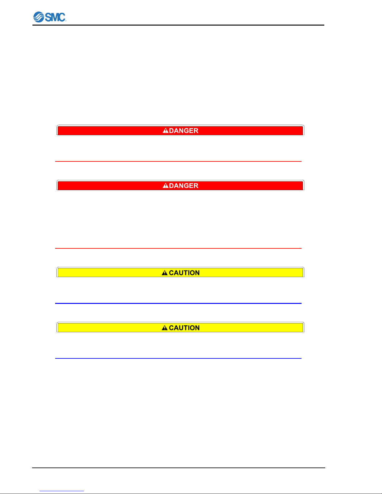
2.1.2 Identification of “Danger”, “Warning”, “Caution” and “Note”
The notifications given in this operation manual aim to assure the safe and correct operation of the
product to prevent injury of operators or damage to the product. The notifications are grouped into four
categories, “Danger”, “Warning”, “Caution”, and “Note”, which indicate the severity of the hazard and
damage and also the degree of emergency. All notifications contain critical matter on safety, so they
shall be carefully observed.
DANGER, WARNING, CAUTION and NOTE signs are in order according to severity (DANGER>
WARNING> CAUTION> NOTE).
Page 12
Safety Instructions
HEC002-A/HEC006-A
2-2
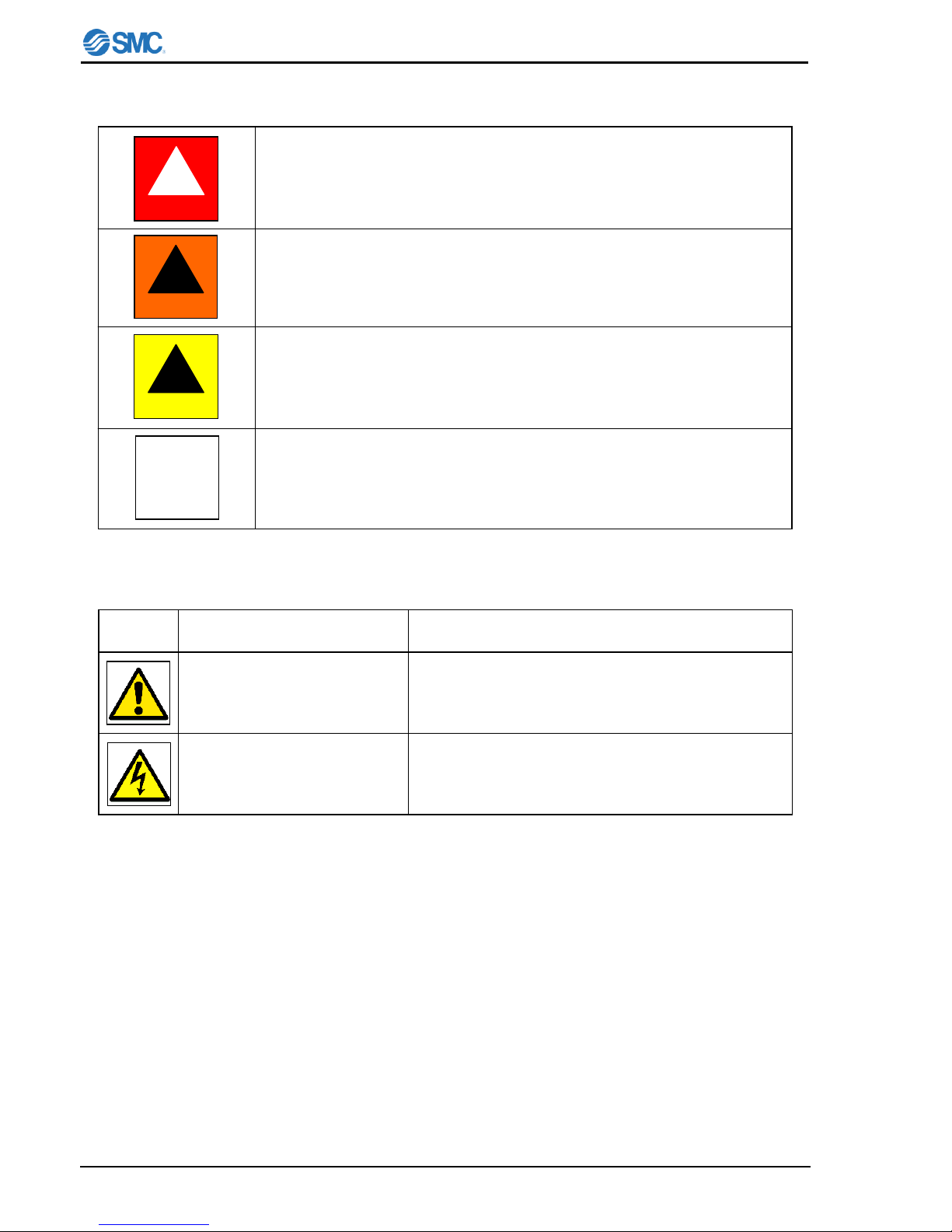
Table2-1 Division of DANGER, WARNING, CAUTION, and NOTE
Table2-2 Meaning of symbols
These paragraphs highlight hazards that would cause serious or even
fatal injuries to workers if handled improperly or important instructions
are ignored.
These paragraphs highlights hazards that might cause serious injuries to
workers if the appropriate procedure is not carried out or warnings are
ignored.
These paragraphs highlights hazards that might cause serious injuries to
workers or might damage the unit, installed devices or products if the
appropriate procedure is not carried out or cautions are ignored.
These paragraphs highlight knowledge which is recommended to be
known to avoid mistakes that likely to happen during operation. Also
anything that might damage the unit or performance of product for
checking is described.
IEC/ISO standard
Attention, consult accompanying
documents
Meaning
Caution, risk of electric shock
Symbol
IEC 348
ISO 3864, No. B.3.6
!
DANGER
!
WARNING
!
CAUTION
NOTE
Page 13
Safety Instructions
HEC002-A/HEC006-A 2-3
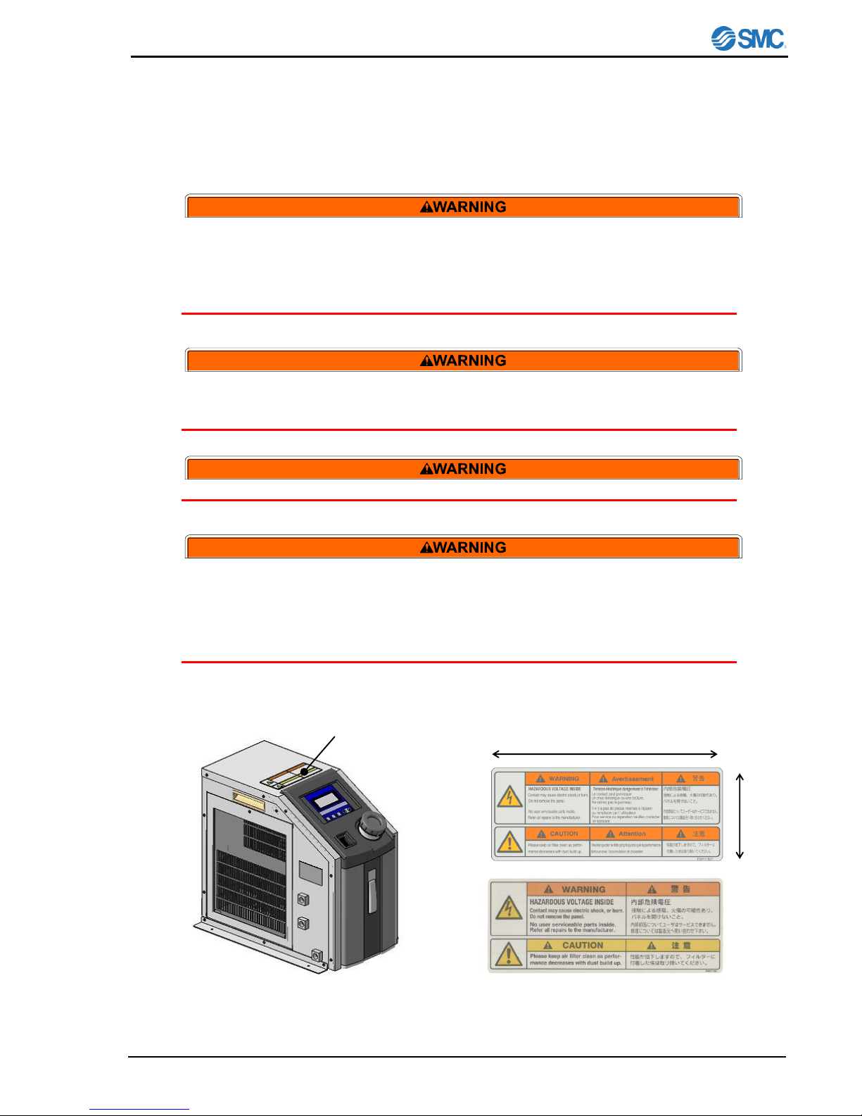
2.2 “Warning” label and “Caution” label
This product is provided with “Warning” labels and “Caution” labels to inform the operator of hazards
related to the product. Check the contents and position of all labels before starting the work.
The product shall be handled only by trained personnel only.
Transportation, installation and maintenance including dangerous work
shall be done by persons who have full knowledge and experience on
the product and the system. Cover panels of the product shall be
opened only by qualified service technicians or qualified personnel.
Read all warning and caution labels carefully and keep them in mind. Do
not peel off or rub alert warning and caution labels.
Confirm locations of alert warning and caution labels.
This product cannot be used for the device related to food.
If abnormal conditions, such as abnormal noise or smoke, or water
leakage appeared, take the following actions:
Shut down power.
Stop water radiating water supply
Contact an authorised SMC dealer for repair
2.2.1 The position of attached “Warning” label and “Caution” label
Fig. 2-1 The position of attaching “Warning”
label and “Caution” label
“Caution” label and “Warning” label
60mm
150mm
Fig.2-2 Detail of “Warning” and “Caution” label
for HEC002-A
for HEC006-A
Page 14
Safety Instructions
HEC002-A/HEC006-A
2-4
2.3 Precautions for running (safety interlock)
This is a function to protect personnel, to restrict operation, that may cause damage to the product or
facility, and to remove dangers related to safety.
This unit has several interlock functions, which activate when dangerous operation or condition occurs to
stop operation and make it safe.
See “2.3.1 Interlock list” for contained function.
During operation or maintenance of the product, do not disable the
interlock function of any device. Otherwise unexpected personnel injury
or damage to the product may occur.
When turning on/off the power observe the procedure. Otherwise
unexpected malfunction or danger may occur.
When maintaining, cleaning or in case of emergency, turn off the power
source.
After identifying a problem be sure to check the cause and take
necessary countermeasures before turning on the power.
When the power supply is restarted after turned off once, keep time
interval at least 1sec. The restart of supply within that interval may break
the unit.
Please do not use the device which generates the electromagnetic
radiation such as cellular phones beside the unit. There is a possibility
that the unit mis-operates.
Page 15
Safety Instructions
HEC002-A/HEC006-A 2-5
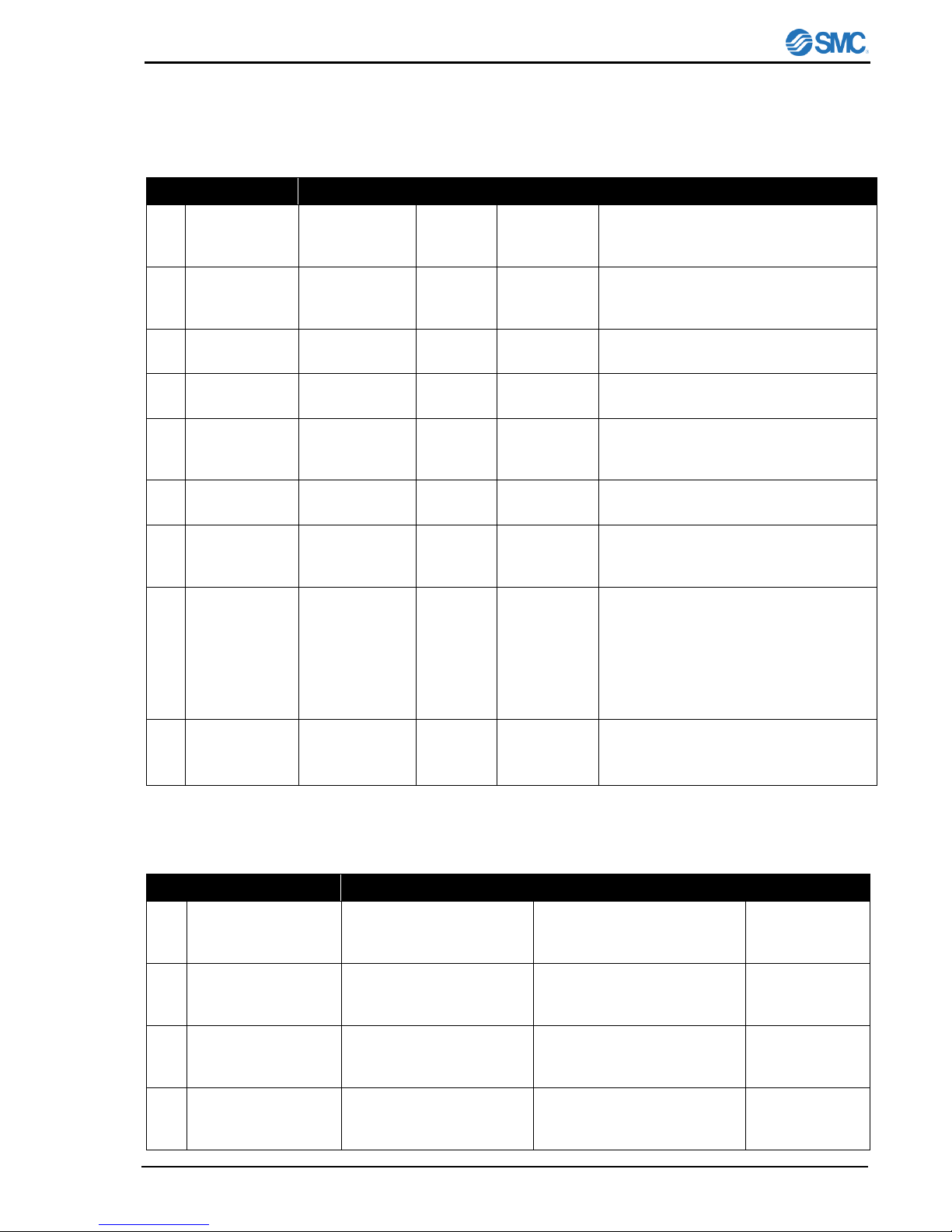
2.3.1 Interlock list
Table2-3 Safety interlock list (Part 1)
No.
Description
Part
Quantity
Location
Cause
1
Overheat in
Heat
Exchanger
Thermostat
1
Heat
Exchanger
Detects abnormal heat in heat
exchanger.
2
Switching
power supply
failure
Thermostat
2
Power supply
Detects abnormal current, voltage or
heat.
3
Overheat in
Heat Sink
Thermostat
1
Heat sink
Detects overheat in Heat Sink.
4
Low circulating
fluid level
Level sensor
1
Reservoir
Detects lowering of circulating fluid level
in reservoir.
5
Detection of
breakage of
temp. sensor
Controller
internal circuit
-
Detects breakage and short circuit of
temp. sensor and cables.
6
Excessive
temp. increase
Controller
internal circuit
-
Detects temp. input value not less than
70 C.
7
Excessive
temp.
decrease
Controller
internal circuit
-
Detects temp. input value not more than
0 C.
8
Abnormal
output
(Overload)
Controller
internal circuit
-
Works when temp. change is smaller
than over load detection temp.(selected
between 0.1 to 9.9 C) even if 100%
output continues during overload
detection time (selected between 0 to
99min.) When 0 is set, the alarm doesn’t
arise.
9
Low flow rate
(Option)
Flow sensor
-
Detects lowering of flow rate at
0.7±0.3L/min or less.
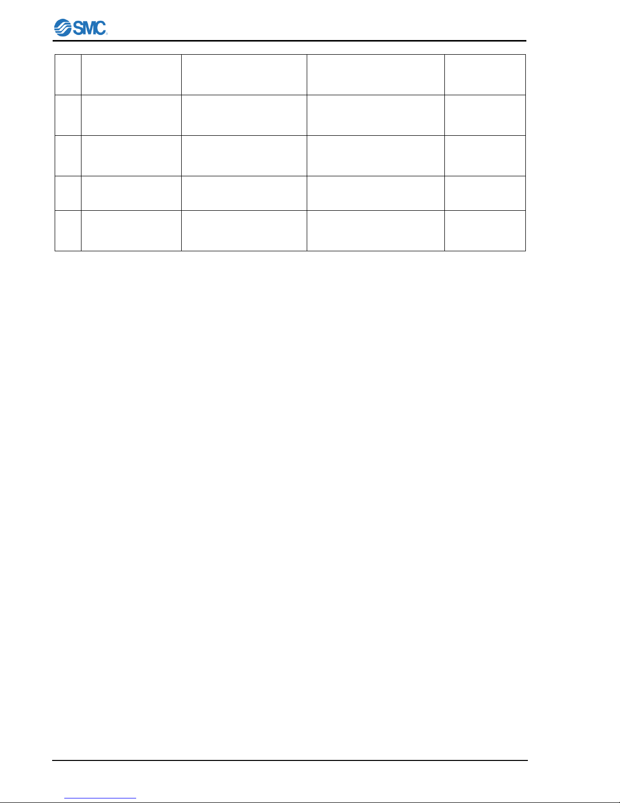
Table2-4 Safety interlock list (Part 2)
No.
Description
Condition of unit
Indication
How to reset
1
Overheat in Heat
Exchanger
Shuts off power supply to
the Heat exchanger, Pump
and Fan.
Error indication on display.
(ERR14)
Restart power
supply
2
Switching power
supply failure
Shuts off power supply to
the Heat exchanger, Pump
and Fan.
Error indication on display.
(ERR11)
Restart power
supply
3
Overheat in Heat
Sink
Shuts off power supply to
the Heat exchanger, Pump
and Fan.
Error indication on display.
(ERR14)
Restart power
supply
4
Low circulating fluid
level
Shuts off power supply to
the Heat exchanger, Pump
and Fan.
Error indication on display.
(ERR20)
Restart power
supply
Page 16
Safety Instructions
HEC002-A/HEC006-A
2-6
5
Detection of
breakage of temp.
sensor
Shuts off power supply to
the Heat exchanger, Pump
and Fan.
Error indication on display.
(ERR17)
Restart power
supply
6
Excessive temp.
increase
Shuts off power supply to
the Heat exchanger, Pump
and Fan.
Error indication on display.
(ERR12)
Restart power
supply
7
Excessive temp.
decrease
Shuts off power supply to
the Heat exchanger, Pump
and Fan.
Error indication on display
(ERR13)
Restart power
supply
8
Abnormal output
(Overload)
The unit continues to
operate.
Error indication on display
(ERR15)
Restart power
supply
9
Low flow rate
(Option)
Shuts off power supply to
the Heat exchanger, Pump
and Fan.
Error indication on display
(ERR16)
Restart power
supply
2.4 Disposing of product
Contact an industrial waste disposal company for disposal of the product.
To minimize the risk, drain the fluid from the product when it is scrapped. If the fluid is left inside, an
accident and damage can result during transportation.
Page 17
Caution on Installation
HEC002-A/HEC006-A 3-1
3 Caution on Installation
Pay special attention to the safety of all personnel when installing and
transporting the product.
The product is heavy, be careful when installing or moving the product.
Only trained personnel can perform work such as installation,
transportation and maintenance of the product.
3.1 Environment
The product shall be installed in an environment that meets the following requirements.
1) Where the product is not exposed to water, oil or any chemical spills.
2) Where the product is installed horizontally in a stable position .
3) Where the product is installed without interfere the suction and discharge port.
4) Where the product is not exposed to corrosive or flammable gas. (The unit is not explosion proof.)
5) Where the ambient temperature range is between 10 to 35C and the relative humidity range is
between 35 to 80%. No dew condensation is allowed on the unit. Information about due
condensation is shown on “10.2 Calculation of Dew Point”.
6) Where the product is not exposed to noise sources (such as discharging equipment, large relay and
thyristor).
7) Where the there is enough space between power supply cable and communication cable of the
product and power cables of other equipments.
8) Where the product is not exposed to strong electrical or magnetic emissions.
9) Where the power supply and ground connections can be made correctly.
10) Where the product is not exposed to materials such as silicone, which may generate harmful gas.
11) Where the product is not outdoors or in a place with the direct sunshine or heat radiation.
12) Where the product is at an altitude of more than 1000 meters.
Page 18

Caution on Installation
HEC002-A/HEC006-A
3-2
3.2 Installation
If the air inlet of Thermo-con and the outlet opening is not enough, the cooling capacity decreases
due to the rise of the ambient temperature, decrease of the radiating air flow. Install Thermo-con
following condition. Moreover, when the exhaust duct is necessary, prepare it by customer.
3.3 Mounting
The product should be mounted as follows.
1) Use the foot attached to the product for mounting.
2) Then tighten M4 screws (bolts) or equivalent into 4 holes sized to 5mm on the parts marked with
arrow for mounting.
Fig. 3-1 Installation environment
Air IN
Air OUT
Air IN
Air OUT
Fig. 3-2 Installation environment (when the back side
has been blocked)
HEC002:100mm or more
HEC006:500mm or more
HEC002:200mm or more
HEC006:500mm or more
Page 19

Caution on Installation
HEC002-A/HEC006-A 3-3
Fig3-3 Mounting
Be sure to correctly tighten all screws the required torque.
3.4 Piping
1) Ensure the flow rate of the circulating fluid is as high as possible to maintain the temperature
stability. Therefore, the length of the external piping should be minimized and internal diameter
should be as large as possible. Piping must have sufficient strength for the maximum discharge
pressure of the circulating circuit.
2) Likewise, if a tube is bent or multiple elbow fittings are used, the piping resistance will increase and
the flow rate will decrease. If the flow rate falls, the temperature stability will decrease.
3) If installing a tank externally, only a sealed tank should be used. Do not use an open tank.
Ensure that the INLET and OUTLET for circulating fluid is connected
correctly. If any valves are used ensure that they do not restrict the flow,
otherwise low flow my cause an alarm.
3.5 Handling
Transport Thermo-con with both handles.
240(HEC002)
270(HEC006)
300(HEC002)
280(HEC006)
Page 20

Caution on Installation
HEC002-A/HEC006-A
3-4
Page 21

Unit Overview
HEC002-A/HEC006-A 4-1
4 Unit Overview
4.1 Method of identifying model
4.2 Manufacturing years method of display
SERIAL No. M o -0001
4.3 Model No. label
A model No. label is attached to the unit in the position shown below.
Fig.4-1 Position of Model No. label Fig.4-2 Legend of Model No. label
HEC002 – A 5 B - *
Cooling capacity
002
230W
006
600W
Radiating method
A
Air-cooled
Power supply
5
AC100-240V
Serial communication
A
RS-485
B
RS-232C
Option
Nil
With no option
-F
With flow switch
-N
NPT fitting
Mfg. month
o
Jan.
U
Jul. P Feb.
V
Aug.
Q
Mar.
W
Sep.
R
Apr.
X
Oct. S May
y
Nov.
T
Jun.
Z
Dec.
Mfg. year
L
2007
M
2008
N
2009
Serial No.
0001
0002
------
Model No.
label
Page 22

Unit Overview
HEC002-A/HEC006-A
4-2
4.4 Appearance
The appearance and the outline dimensions are as shown below.
HEC002-A
HEC006-A
Fig.4-3 Outside drawings of Thermo-con
240
270
300
390
210
270
300
280
370
240
278
455
390
382
281
436
393
385
Page 23

Unit Overview
HEC002-A/HEC006-A 4-3
4.5 Outline of operation
The unit is operated as explained below.
4.5.1 Electrical diagram
The unit is equipped with electrical circuits as shown below.
Fig.4-4 Electrical diagram
4.5.2 Mechanical system
The unit is equipped with circulating fluid as shown below.
Fig.4-5 Circulating fluid circuit
Reservoir
DC pump
Temp. sensor
Circulating
fluid IN
Circulating
fluid OUT
DC fan
DC fan
Filter
Thermo-module
Heat sink
Heat exchange plate
Membrane
key sheet
LCD
display
Temp. sensor
Thermo-module
DC pump
DC fan
CPU board
Switching
power supply
for CPU board
DC12V
Switching
power supply
for main
DC24V/48V
R
Thermostat
Level switch
RS-485/RS-232C
AC100
to 240V
Power switch
(Circuit protector)
Controller
Power supply
board
DC5V, DC12V
DC24V
External sensor
Alarm output
Chassis
Page 24

Unit Overview
HEC002-A/HEC006-A
4-4
4.6 Functions
4.6.1 Auto tuning
This function sets the values necessary for the control system such as PID (proportional band, integral
time, derivative time and ratio of cooling/ heating gain) automatically.
4.6.2 Offset function
This function controls the temperature slide by an offset value from set point temperature. The range of
offset is -9.99 to 9.99 C. When the circulating fluid is carried to the target object, a certain deviation
occurs between the temperature before the object and the setting temperature of the product due to the
influence of ambient temperature on the piping. In this case, if the deviation is input as the offset value,
the temperature of circulating fluid just before the object can match with setting value.
Internal sensor value for alarm does not include the offset value.
4.6.3 Learning control function
This function lets the product measure the temperature of circulating fluid flowing before temperature
target object by an external temperature sensor and adjusts the offset function automatically to the set
value at a certain sampling interval. The external temperature sensor needs to be prepared separately
by the customer.
4.6.4 External tune control function
This function makes the temperature of circulating fluid consistent to the external (ambient) temperature
all the times. This function lets the product measure the temperature from a temperature sensor
mounted in the customer preferred location, then it adjusts the temperature of the fluid automatically to
the temperature detected by the sensor. The separate temperature sensor needs to be prepared
separately by the customer.
4.6.5 Temperature sensor fine control function
This is a function to finely control the measurement temperature of the control sensor within the range of
-9.99 to 9.99 C separate from offset function. Control sensor can be corrected by inputting difference
(calibration value) between temperature of standard and that of control sensor.
Internal sensor value for alarm includes the fine control value.
Internal sensor value for alarm = Internal sensor value – Fine control value
4.6.6 Setting value memory function
(Function that backs up with EEPROM)
This function backs up all the manually set values to nonvolatile memory (EEPROM). Even if the power
is turned off the set values are saved and will be restored at power on.
4.6.7 Upper/ Lower Temperature Limit Alarm Function
This function raises an alarm when temperature of the circulating fluid is out of allowable upper and
lower range. When the alarm is raised, WRN is indicated on LCD. If circulating fluid temperature returns
to within allowable upper/ lower range, this alarm is automatically canceled. The allowable upper and
lower range of temperature can be set between 0.1 and 10 C.
Page 25

Names and Functions of Components
HEC002-A/HEC006-A 5-1
5 Names and Functions of Components
The parts included into the unit have description and function individually.
5.1 Side view
5.1.1 HEC002
Fig.5-1 HEC002-A
5.1.2 HEC006
Fig.5-2 HEC006-A
Communication
connector
Alarm
connector
EXT. Sensor
connector
Power supply connector
Handle
Circulating fluid
OUT
Communication
connector
Alarm
connector
EXT. Sensor
connector
Power supply connector
Handle
Air filter
Circulating fluid
IN
Circulating fluid
OUT
Handle
Drain Rc1/4
Level
gauge
Air filter
Circulating fluid
IN
Handle
Drain Rc1/4
Level
gauge
Page 26

Names and Functions of Components
HEC002-A/HEC006-A
5-2
5.1.3 Air Filter
Fig.5-3 Air Filter
Please keep air filter clean as performance decreases with dust build up.
We will recommend the removal of dust once every three months.
Please remove dust with the cleaner, do not use water to clean.
5.2 Top view
The parts attached to the top of Thermo-con have description and function individually as shown below.
Fig.5-4 Top view
Operation panel and
Display
Reservoir Cap
Air Filter
The Thermo-con adopts air-cooled heat
exchanger not to allow dust to enter easily
inside. However, should the dust be allowed
and attached on the filter, the filter may
become unable to function properly. To prevent
this, the filter should be taken out by removal of
circled screws and cleaned periodically.
Power switch
Page 27

Names and Functions of Components
HEC002-A/HEC006-A 5-3
5.2.1 Operation panel
Fig.5-5 Operation panel
5.2.2 Display
Fig.5-6Display
E R R 1 1 W R N
P
V < 3 1 .
6
C #
1 S
V
3 0 .
0 C
M O D
E N o r m a
l
SEL key
Used to change
setting mode.
AT key
Used to start and
stop auto tuning.
Up and Down Key
Used to change set
value in each setting
mode.
RET key
Used to fix set value or
return to present temp.
status indication.
2nd, 3rd line
Current
temp.[PV]]and target
temp.[SV] during
normal operation.
When the alarm
arises, the error is
indicated instead and
during setting mode
selection, the
selected setting mode
is indicated.
1st line
Indicates No. corresponding
to the alarm which arises
and [WRN] comes to light
up when temp. upper or
lower limit warning occurs.
4th line
Indicates control operation
mode during normal
operation and set values
during setting mode
selection.
Page 28

Names and Functions of Components
HEC002-A/HEC006-A
5-4
5.2.3 Reservoir Cap
Fig.5-7 Reservoir Cap
5.3 Auto tuning function
If controlled temp. fluctuates constantly after reaching the
target temp., perform auto tuning. Controller calculates
optimum control PID and set automatically. Auto tuning
may require time depending on conditions.
1) Select "2" in control operation choices
2) Pressing [AT] key to light "AT" indicator and start auto
tuning.
3) Pressing [AT] key stops auto tuning. (“AT” indicator
turns off)
4) ”AT" indicator turns off when auto tuning completes. If
not completed after 20min. [ERR19] (AT abnormal)
occurs.
5) If auto tuning is no successful, reset to default value, or
input the optimum value.
Reservoir Cap
Removed to supply circulating
fluid before operation. Replace
cap before starting operation.
Counter-clockwise to open
Clockwise to close.
Gasket (Included)
Between the reservoir cap and reservoir
for sealing.
Under a circumstance where a tank
get negative pressure, remove the
gasket after confirming that the
circulating fluid will not flow back when
it the product stopped.
C o n t r o l
O p e r a t i o n
M O D E < 2 : A
T
AT
Page 29

Specifications
HEC002-A/HEC006-A 6-1
6 Specifications
6.1 Specification table
The specifications of the Thermo-con is as shown below.
6-1 Specifications
Item
Spec.
Model No.
HEC002-A
HEC006-A
Operation temp. range
10.0 to 60.0 C (No dew condensation)
Indication temp. range
-9.9 - 80.0 C
Ambient environment
Temp. :10 to 35 C
Humidity : 35 to 80%RH
Environment : No corrosive gas, solvent such as thinner and flammable gas
Storage environment
Temp. :-40 to 70 C (No dew condensation and icing)
Humidity : 5 to 95%RH
Environment : No corrosive gas, solvent such as thinner and flammable gas
Accuracy related to temp.
Indication accuracy: +/- 0.2 C.
Stability: +/- 0.01 to 0.03 C (Circulating fluid OUT is directly connected with IN)
Cooling capacity
(Water)
Approx.230W
(Set temperature25C and ambient
temperature 25C)
Approx.600W
(Set temperature25C and ambient
temperature 20C)
Circulating fluid
Circulating fluid : Water
Reservoir capacity : Approx.1.2L
Pump
Max. pressure: 0.09MPa
Max. pressure: 0.1MPa
Wetted materials
SUS303, SUS304, EPDM, Ceramic, PPS glass 30%, Carbon
Polyethylene, Polyurethane
Piping port size
Circulating fluid IN/OUT : Rc1/4
Circulating fluid drain : Rc1/4
Circulating fluid IN/OUT : Rc3/8
Circulating fluid drain : Rc1/4
Power supply voltage
Single phase AC100-240V, 50/60Hz
Current consumption
8A(100V) to 3A(240V)
10A(100V) to 4A(240V)
Inrush current
50A or less
Over current protection
15A circuit protector
Insulation resistance
50M or more (DC500V, with surge absorber removed)
Acoustic noise
55dBA
65dBA
Cooling method
Air cooled
Main functions
Auto tuning, Off set, Temperature sensor fine control, Temp. upper and lower
limit alarm, Output shut off alarm, Serial communication (RS-232C)
Input operation and
indications
Membrane key sheet
LCD display panel (with back light)
Temp. sensor
Resistance thermometer sensor (Pt100, 3-wire, class A, 2mA)
(both internal sensor and external sensor)
Painting color
Urban white
Mass (at dry)
Approx.17.5kg (with feet)
Approx.27.5kg (with feet)
IP class
IP20 (IEC60529)
Page 30

Specifications
HEC002-A/HEC006-A
6-2
6.2 Performance chart
Value on performance chart is not guaranteed value but representative value. The value used for
consideration should not be the very limit for the safety.
1) Cooling capacity
Fig. 6-1 Cooling capacity
2) Heating capacity
Fig. 6-2 Heating capacity
3) Pump capacity
The pressure on Y axis stands for discharge pressure of circulating fluid from Thermo-con.
0
200
400
600
800
1000
1200
1400
10 15 20 25 30 35 40 45 50
Fluid temperature degC
Cooling capacity W
Fluid: water
Ambient 30C
Ambient 20C
Ambient 15C
200
400
600
800
1000
1200
1400
1600
1800
2000
10 15 20 25 30 35 40 45 50
Fluid temperature degC
Heating capacity W
Fluid: water
Ambient 30C
Ambient 20C
Ambient 15C
0
100
200
300
400
500
10 15 20 25 30 35 40 45 50
Circulating fluid temperature degC
Cooling capacity W
Fluid: water
Ambient 15C
Ambient 25C
Ambient 35C
0
100
200
300
400
500
600
700
800
900
1000
10 15 20 25 30 35 40 45 50
Circulating fluid temperature degC
Heating capacity W
Fluid: water
Ambient 15C
Ambient 25C
Ambient 35C
Page 31

Specifications
HEC002-A/HEC006-A 6-3
HEC002-A
HEC006-A
Fig. 6-3 Pump capacity
0.00
0.02
0.04
0.06
0.08
0.10
0 1 2 3 4
Flow rate L/min
Pressure MPa
Fluid: water
0.00
0.02
0.04
0.06
0.08
0.10
0.12
0 2 4 6 8 10
Flow rate L/min
Pressure MPa
Fluid: water
Page 32

Specifications
HEC002-A/HEC006-A
6-4
Page 33

Preparation for Operation
HEC002-A/HEC006-A 7-1
7 Preparation for Operation
7.1 Preparation for circulating fluid
The piping for circulating fluid is
connected as below.
1. The piping for circulating fluid
is located at the left side face.
2. The same fittings are used for IN and OUT of the
circulating fluid.
The fitting which can mate them needs to be prepared separately. When the fitting is connected, be
sure to hold the fitting (block) mounted at Thermo-con with spanner, etc.
Thread size of fitting for circulating fluid:
HEC002-A; Rc1/4
HEC006-A; Rc3/8
A plug is mounted on DRAIN port for circulating fluid. When the
piping for drain is connected, remove this plug beforehand.
Drain the circulating fluid before performing any
maintenance.
Width across flat of plug: 6mm
DRAIN port size: Rc1/4
Fluid other than water is not to be used as circulating fluid. Using such a
fluid might lead to fluid leakage and damage of the pump.
If a tank released to atmosphere is mounted outside, minimize the
piping resistance at RETURN of circulating fluid. If the piping
resistance is high, the causing the built-in reservoir of Thermo-con can
have negative pressure resulting in deformation and crack. The built-in
reservoir of Thermo-con is made of plastic and must not be subject to
negative pressure larger than -0.02MPa.
Once the plug is removed from the drain port, the leakage from it is not
guaranteed. Therefore, seal it with PTFE seal tape etc. and ensure there
is no leakage from it before operation.
Page 34

Preparation for Operation
HEC002-A/HEC006-A
7-2
7.2 Power supply
The power supply shall be connected with attached power supply cable.
Confirm the power supply at factory has enough capacity and the voltage is within specified value
beforehand (with reference to electrical specifications of the power supply). This unit is provided with the
power supply cable. The power supply cable shall be connected properly in accordance with Chapter 10
“Power Supply Cable”.
Electric specifications of the power supply
7.3 Grounding
Be sure to provide the grounding. Use medical plug with protection earth when the unit is used for
medical equipment. PE line of the power supply cable is available for grounding. Do not hold the
ground in common with the ones for equipment which generates strong electromagnetic noise or
high frequency.
7.4 Supply circulating fluid and drain
<Supply circulating fluid>
1. Confirm the power switch is turned off.
2. Take off the reservoir cap of the product.
3. Fill the circulating fluid for the reservoir. The inlet of the
reservoir is not so large and there is a possibility of spillage
of circulating fluid. Pay attention when filling the circulating
fluid.
Stop the filling once the level of fluid reaches “H” level.
4. Turn on the power switch to fill the piping with the fluid.
5. When the piping is filled with the circulating fluid, the level of
the reservoir lowers and low circulating fluid alarm (ERR20)
arises accordingly. Then, turn off the power supply once
again.
6. Repeat the step from 3 to 6 until ERR20 alarm doesn’t
appear anymore. Then, replace the cap on the reservoir and
tighten it securely.
7. Keep the fluid level between H and L of the level indicator.
8. Water pressure during normal operation becomes under 0.1
MPa.
<Drain circulating fluid>
1. Drain circulating fluid from the drain port. Open the reservoir cap would be helpful for draining.
2. To drain from the piping, blow the air (0.1MPa, about 1 minute) from Fluid IN to Fluid OUT. Tighten
the tank lid and drain port while blowing
Never touch the switch with wet hands to avoid electrical shock.
ERR20
ON
AC100-240V, 50/60Hz
Single phase
Page 35

Preparation for Operation
HEC002-A/HEC006-A 7-3
Operation of the pump with the plenty of air left in the piping for
prolonged period may cause the pump to break. Exhaust the air enough
from the piping before starting operation of the pump.
Take enough care not to spill the feed water over the case when
supplying water to the reservoir. When it is spilt by mistake, wipe it off
immediately and supply the power after it dries. If this procedure is
neglected, it may cause breakdown of the equipment.
Do not perform operation under the condition which lowers the flow rate
significantly, such as closing the valve. Other wise, the temperature
might be beyond control.
If the fluid with low conductivity such as DI water is used as circulating
fluid, it causes static electricity due to friction and damages the
temperature sensor and other electric components of this unit. Take a
measure to minimize static electricity from circulating fluid.
If the power switch is turned on without circulating fluid, the pump is
damaged.
The product is damaged when driving for a long term with the
temperature staggered periodically after reaching the target temperature.
Please set the PID value again by using auto-tuning function (see
section 5.3).
7.5 Check・Repair
The following checks shall be performed before operation.
7.5.1 Daily check
1) Indication of display panel : Check temperature condition and confirm whether or not the alarm
occurs.
2) Filter : Confirm there is not attachment of the dust on the filter at suction port. A lot of attachment
may impair performance. We will recommend the removal of dust once every three months.
3) Confirm there is no leakage of circulating fluid or no bending or crush of the piping of circulating
fluid.
4) Confirm there is no abnormal sound or smell or abnormal heating of the case.
Page 36

Preparation for Operation
HEC002-A/HEC006-A
7-4
Remove the dust attached to a filter by vacuum cleaner to prevent
degrading of performance. The recommended interval of removal is
once per 3 months. Do not use water or boiled water since it leads to
generation of rust at a frame.
7.5.2 Check after seismic vibration and impact
1) Piping: Confirm there is no defect including disconnection in piping.
2) Electrical wiring: Confirm there is disconnection of the connector from the cable.
3) Mounting condition: If the Thermo-con is mounted for operation, confirm the Thermo-con is
mounted securely.
4) Circulating fluid: Confirm there is no leakage.
5) Others: Confirm there is no abnormal sound or smell or abnormal heating of the case.
7.5.3 Repair and maintenance
The repair and maintenance services of this unit are performed only at our factory. The service requiring
a trip regardless of inside and outside of Japan is not provided. Also, when this unit is returned for these
purposes, drain the fluid from Thermo-con.
Additionally, it is recommended to prepare spare units to minimize downtime due to those repair and
maintenance services.
Drain the fluid from Thermo-con when it is returned for the repair and
maintenance service. If the fluid is left inside, an accident and damage
can result during transportation.
After washing with DI water, return the product when the fluid was other
than water. The acceptance might be refused according to the state of
the product.
Page 37

Operation
HEC002-A/HEC006-A 8-1
8 Operation
This chapter describes the detailed information on how to operate.
8.1 Condition after power up
1.Indication of software version
When power is turned on, software version is
indicated on display panel for approx. 1 sec.
(Ex. : 1.0)
Please do not use devices that generate electromagnetic radiation such
as cellular phones near the product. There is a possibility that the
product malfunctions.
8.2 How to operate
1. The different 3 levels are available depending on the content,
which needs to be set.
Level 1 : Used in normal operation. Setting of target temp.
and offset are included.( Refer to 8.3.)
Level 2 : Used at maintenance and initial setting and the
setting of controller PID is included.( Refer to
8.4.)
Level 3 : Used rarely for the purpose other than initial
setting and communication setting is included.(
Refer to 8.5)
2. [SEL] key
Used to show the item, which needs to be changed in
selected mode level.
3. [ ] key (up/down key)
Used to change the value of the item shown by [SEL] key.
4. [RET] key
Used to fix the value changed by [ ]key. Press once
again to return to current temp. indication.
5. [AT] key
Used to start auto tuning in auto tuning mode (control
operation mode : 2). When pressed during auto tuning, the
auto tuning is stopped. ( Refer to 5.3)
Operation
+
Operation
+
Operation
S O F T V E S I O N
1 . 0
Page 38

Operation
HEC002-A/HEC006-A
8-2
8.3 Setting Mode, Level 1
The method to enter to and return from setting mode Level 1 and which mode can be set in the level are
explained below.
8.3.1 How to enter and return
Press [SEL] key while power is turned on. Then, the indication on [MODE] is changed depending on the
number of press and the data in the indicated mode can be set. To return to current temperature
indication, press [RET] key.
When no input is done within 1 minute regardless of setting mode, the
current temperature indication is returned automatically.
8.3.2 Available mode in Level 1
The mode which can be set in setting mode Level 1 is as shown on Table 8-1. The mode available in
Level 1 is supposed to be used in normal operation including target temp. and offset.
The inputted data is written in EEPROM and memorized after the power
supply is turned off. The writing can be done up to 1 million times.
Table8-1 Available mode in Level 1
No.
Modes
Setting contents
Setting range
(Min. increment)
Default
1
Target Temp.
(No indication on display)
Sets target temp. for control.
10.0 to 60.0 C
(0.1 C)
25.0
2
Control Operation
Selects control operation mode from
those shown below.
0 : Pump stop(No control)
1 : Normal(normal control operation)
2 : AT(auto tuning)
3: Learn (learning control)
4: External (external tune control)
0,1,2,3,4
1
3
External Sensor Sampling
Cycle
Sets sampling cycle for learning
control or external tune control. (Not
indicated during normal control.)
10 to 999sec
(1sec)
180
4
Offset Value
Indicates the offset value of the
circulating fluid temperature used as
reference value by the controller (SV
+ Offset).
-9.99 to 9.99 C
(0.01 C)
0.00
5
Allowable Upper
Temp. Range
Sets upper limit of temp. range which
causes the warning to arise.
0.1 to 10.0 C
(0.1 C)
1.5
6
Allowable Lower
Temp. Range
Sets lower limit of temp. range which
causes the warning to arise.
0.1 to 10.0 C
(0.1 C)
1.5
Page 39

Operation
HEC002-A/HEC006-A 8-3
7
High Temp. Cutoff
Sets upper limit of temp. which the
internal temp. sensor detects and
judges the unit should be shut off.
11.0 to 70.0 C
(0.1 C)
70.0
8
Low Temp. Cutoff
Sets lower limit of temp. which the
internal temp. sensor detects and
judges the unit should be shut off.
0.0 to 59.0 C
(0.1 C)
0.0
* How to return default value: Turn on the power supply with pressing [SEL] and [RET] keys,.
At this time, the settings of Level 2 and Level 3 are also reset.
8.4 Setting mode, Level 2
The method to enter to and return from setting mode Level 2 and which mode can be set in the level are
explained below.
8.4.1 How to enter and return
Press [SEL] and [ ] keys at the same time while power is turned on. Then, the indication on [MODE] is
changed depending on the number of press and the data in the indicated mode can be set. To return to
current temp. indication, press [RET] key twice.
When no input is done within 1 minute regardless of setting mode, the
current temperature indication is returned automatically.
8.4.2 Available mode in Level 2
The mode, which can be set in setting mode Level 2, is as shown on Table 8-2. The mode available in
Level 2 is supposed to be used normally for initial setting and maintenance and control PID is included.
The inputted data is written in EEPROM and memorized after the power
supply is turned off. The writing can be done up to 1 million times.
Page 40

Operation
HEC002-A/HEC006-A
8-4
Table8-2 Available mode in Level 2
No.
Modes
Setting contents
Setting range
(Min. increment)
Default
1
Fine Control of
Internal Sensor
Sets the fine adjusting value to
calibrate the internal temp. sensor.
-9.99 to 9.99 C
(0.01 C)
0.00
2
Fine Control of
External Sensor
Sets the fine adjusting value to
calibrate the external temp. sensor
available optionally.
-9.99 to 9.99 C
(0.01 C)
0.00
3
PB Range
Sets PB (Proportional Band) range used
for PID control.
0.3 to 9.9 C
(0.1 C)
0.6
(2.0)
4
ARW Range
Sets integral operation range of PID
control.
ARW: Anti Reset Windup
0.3 to 9.9 C
(0.1 C)
1.0
(2.2) 5 I Constant
Sets integral time used for PID control.
1 to 999sec
(1sec)
150
(50)
6
D Constant
Sets differential time used for PID
control.
When 0 is set, differential operation is
not made.
0.0 to 99.9sec
(0.1sec)
0.0
7
Heating/Cooling Ratio
Sets output ratio of cooling to heating to
compensate difference of gain between
them.
10 to 999%
(1%)
200
8
Overload Judging
Temp. Range
Sets the temp. range for judgment of
overload(accompanying abnormal
output alarm ERR15).
0.1 to 9.9 C
(0.1 C)
0.2
9
Overload Judging Time
Sets time for judgment of overload
(accompanying abnormal output alarm
ERR15). When 0 is set, the alarm
doesn’t arise.
0 to 99min
(1min)
10
10
Output Ratio
Shows output ratio of thermo module
by 1%. The prefix symbol “-” stands for
cooling and no prefix stands for
heating.
-100 to 100%
(1%)
-
11
Upper/Lower Temp.
Alarm Sequence
Determines whether or not temp.
upper/lower limit alarm is output when
power is turned on.
On : Output
Off : Not output
On, Off
Off
* How to return default value: Turn on the power supply with pressing [SEL] and [RET] keys. At this time, the
settings of Level 1 and Level 3 are also reset.
* The default value indicated in ( ) is an optimal value. The value is inputted at that time of shipment factory. If
turn on the power supply with pressing [SEL] and [RET] keys, set up the value indicated in ( ).
Page 41

Operation
HEC002-A/HEC006-A 8-5
8.5 Setting mode, Level 3
The method to enter to and return from setting mode Level 3 and which mode can be set in the level are
explained below.
8.5.1 How to enter and return
Press [SEL] and [ ] keys at the same time while power is turned on. Then, the indication on [MODE] is
changed depending on the number of press and the data in the indicated mode can be set. To return to
current temp. indication, press [RET] key twice.
When no input is done within 1 minute regardless of setting mode, the
current temperature indication is returned automatically.
8.5.2 Available mode in Level 3
The mode, which can be set in setting mode Level 3, is as shown on Table 8-3. The mode available in
Level 3 is supposed not to be used normally for the purpose other than initial setting and the setting
related to communication is included.
The inputted data is written in EEPROM and memorized after the power
supply is turned off. The writing can be done up to 1 million times.
Table8-3 Available mode in Level 3
No.
Modes
Setting contents
Setting range
(Min. increment)
Default
1
Unit Number
Sets the unit No. used. This is
applicable only when multiple Thermocon is used.
0 to F (Hex decimal)
0
2
Baud Rate
Sets baud rate for communication.
600,1200,2400,4800
9600,19200b/s
1200
3
Parity Bit
Sets parity bit for communication.
Without : No parity
Odd : Odd
Even : Even
Without, Odd, Even
Without
4
Data Length
Sets data length for communication.
7Bits, 8Bits
8
5
Stop Bit
Sets stop bit for communication.
1Bit, 2Bits
1
* How to return default value: Turn on the power supply with pressing [SEL] and [RET] keys. At this time, the
settings of Level 1 and Level 2 are also reset.
Page 42

Operation
HEC002-A/HEC006-A
8-6
8.6 Detail of setting mode level
The each setting mode level is explained below in detail.
8.6.1 Setting mode, Level 1
1. Indication of current temperature [PV]
Indication range: -9.9 to 80.0 C
Min. increment: 0.1 C
Indicated content: #1 Temperature detected by internal temp. sensor
#2 Temperature detected by external temp. sensor
(When the external sensor is not connected,
“HHH” would be indicated.)
#1 and #2 change when [ ] or [ ] is pressed.
2. Target temperature (no indication on display)
Setting range : 10.0 to 60.0 C
Min. increment : 0.1 C
Indicated content : [SV] : Target temp.(Ex. : 25.0 C)
Function : Sets target temperature
3. Control Operation
Setting range : 0,1,2,3,4
Indicated content : Number and description of control
operation mode.(Ex. : 1:Normal)
Function : Selects control operation mode from those
shown below.
0 : Stop of control (Pump Stop)
1 : Normal (normal control operation)
2 : AT (auto tuning)
3 : Learning control (Learn)
4 : External tune control (External)
When a learning control and an external tuning control are selected, measurement temperature (#2) of
an external temperature sensor is displayed.
When an external tuning control is selected, the target temperature is changed at any time. When the
control mode changes from external tune mode to normal mode, the target temperature returns to the
previous value.
<How to perform auto tuning>
1) Select “2” in control operation.
2) Press [AT] key to light up “AT” indicator. The auto tuning starts.
3) To stop auto tuning, press [AT] key again. (“AT” indicator goes off.)
4) When auto tuning is finished, “AT” indicator goes off. If the auto tuning is not finished within
20min, [ERR19] (AT error) arises.
5) If the auto tuning fails, change the PID values to the set values at the time of shipment from
factory or input the optimum values.
4. External sensor sampling cycle setting mode
[External sensor sampling cycle]
Setting range: 10 to 999sec
Min. increment: 1sec
Indicated content: External sensor sampling cycle
(Ex.: 180sec)
Function: Sets sampling cycle of external sensor for learning control or external tune control.
P V < 2 3 . 0 C # 1
S V 2 5 . 0 C
M O D E
C o n t r o l
O p e r a t i o n
M O D E < 1 : N o r m a l
P V 2 3 . 0 C # 1
S V < 2 5 . 0 C
M O D E
E x t e r n a l S e n s o r
S a m p l i n g C y c l e
M O D E < 1 8 0 s e c
P V < 2 3 . 0 C # 2
S V 2 5 . 0 C
M O D E
Page 43

Operation
HEC002-A/HEC006-A 8-7
5. Offset Value
Setting range : -9.99 to 9.99 C
Min. increment : 0.01 C
Indicated content : Offset value(Ex. : -0.15 C)
Function : It allows the change of the difference between
the controller reference value and set value by
offset.
For example, if -0.15 C is set here, the actual reference temperature for control is
lower than the indicated SV by 0.15 C.
6. Allowable Upper Temp. Range
Setting range : 0.1 to 10.0 C
Min. increment : 0.1 C
Indicated content : Temp. from target to upper limit
(Ex.: 1.5 C)
Function : Sets upper limit of temp. where the warning arises. The difference between target
temp. and upper limit temp. should be input. Therefore, if the target temp. is 23.0
C and 1.5 C is set in this item, the warning [WRN] arises when temp. exceeds
24.5 C.
7. Allowable Lower Temp. Range
Setting range : 0.1 to 10.0 C
Min. increment : 0.1 C
Indicated content : Temp. from target to lower limit
(Ex. : 1.5 C)
Function : Sets lower limit of temp. where the warning arises. The difference between target
temp. and lower limit temp. should be input. Therefore, if the target temp. is 23.0
C and 1.5 C is set in this item, the warning [WRN] arises when temp. lowers
21.5 C.
8. High Temp. Cutoff
Setting range : 11.0 to 70.0 C
Min. increment : 0.1 C
Indicated content : High temp. cutoff by internal temp.
sensor (Ex. : 70.0 C).
Function : Sets upper limit of temp. at which the internal temp. sensor detects and judges the
unit should be shut off. When the temp. set in this item is reached, the alarm
[ERR12] arises.
9. Low Temp. Cutoff
Setting range : 0.0 to 59.0 C
Min. increment : 0.1 C
Indicated content : Low temp. cutoff by internal temp.
sensor (Ex. : 0.0 C)
Function : Sets lower limit of temp. at which the internal temp. sensor detects and judges the
unit should be shut off. When the temp. set in this item is reached, the alarm
[ERR13] arises.
O f f s e t V a l u e
M O D E < - 0 . 1 5 C
A l l o w a b l e U p p e r
T e m p . R a n g e
M O D E < 1 . 5 C
A l l o w a b l e L o w e r
T e m p . R a n g e
M O D E < 1 . 5 C
H i g h T e m p .
C u t o f f
M O D E < 7 0 . 0 C
L o w T e m p . C u t o f f
M O D E < 0 . 0 C
Page 44

Operation
HEC002-A/HEC006-A
8-8
8.6.2 Setting mode, Level 2
1. Fine Control of Internal Sensor
Setting range : -9.99 to 9.99 C
Min. increment : 0.01 C
Indicated content : Fine adjusting value for internal
temp. Sensor (Ex. : -0.07 C)
Function : Sets the fine adjusting value to calibrate the internal temp. sensor. If -0.07 C is set
in this item, the reading of temp. sensor is higher by 0.07 C and actually, the temp. is
controlled to lower one by 0.07 C.
2. Fine Control of External Sensor
Setting range : -9.99 to 9.99 C
Min. increment : 0.01 C
Indicated content : Fine adjustment value for external
temp. sensor(Ex. : 0.05 C)
Function : Sets the fine adjusting value to calibrate the external temp. sensor if it is mounted
optionally. If 0.05 C is set in this item, the reading of temp. sensor is lower by 0.05
C and actually, the temp. is controlled to higher one by 0.05 C.
3. PB Range
Setting range : 0.3 to 9.9 C
Min. increment : 0.1 C
Indicated content : PB range(Ex. : 2.0 C)
Function : Sets PB (Proportional Band) range used for
PID control.
4. ARW Range
Setting range : 0.3 to 9.9 C
Min. increment : 0.1 C
Indicated content : ARW range (Ex.: 2.2 C)
Function : Sets integral operation range of PID control. If this value is set less than PB range,
the set temperature can’t be achieved. Therefore set it above PB range.
ARW: Anti Reset Windup
5. I Constant
Setting range : 1 to 999sec
Min. increment : 1sec
Indicated content : I constant(Ex. : 50sec)
Function : Sets integral time used for PID control.
F i n e C o n t r o l o f
I n t e r n a l S e n s o r
M O D E < - 0 . 0 7 C
F i n e C o n t r o l o f
E x t e r n a l S e n s o r
M O D E < 0 . 0 5 C
P B R a n g e
M O D E < 2 . 0 C
A R W R a n g e
M O D E < 2 . 2 C
I C o n s t a n t
M O D E < 5 0 C
Page 45

Operation
HEC002-A/HEC006-A 8-9
6. D Constant
Setting range : 0.0 to 99.9sec
Min. increment : 0.1sec
Indicated content : D constant(Ex. : 0.0sec)
Function : Sets differential time used for PID control.
When 0 is set, this function becomes invalid.
7. Heating/Cooling Ratio
Setting range : 10 to 999%
Min. increment : 1%
Indicated content : Heating/cooling gain ratio(Ex. : 200%)
Function: Sets output ratio of cooling to heating to
compensate difference of gain between them.
8. Overload Judging Temp. Range
Setting range : 0.1 to 9.9 C
Min. increment : 0.1 C
Indicated content : Overload judging temp. range (Ex. :
0.2 C)
Function : Sets the temp. range for judgment of product
overload (accompanying abnormal output
alarm ERR15).
9.Overload Judging Time
Setting range : 0 to 99min
Min. increment : 1min
Indicated content : Overload judging time(Ex. : 10min)
Function : Sets time for judgment of product overload
(accompanying abnormal output alarm
ERR15). When 0 is set, the alarm doesn’t
arise.
10. Output indication mode [Output Ratio]
Setting range : -100 to 100%
Min. increment : 1%
Indicated content: Thermo module output ratio (Ex.: -73%)
Function: Indicates Thermo module output ratio with
increment of 1%. “+” is not indicated but “+”
means heating and “-“ means cooling.
11.Upper/Lower Temp. Alarm Sequence
Setting range : On, Off
Indicated content : Use of temp. upper/lower limit alarm
sequence(Ex. : Off)
Function : Determines whether or not temp. upper/lower
limit alarm is output when power is turned on.
On : Output
Off : Not output (Alarm for high and low temperature limit is not detected until the
temperature reaches the target temperature after the power is supplied.)
D C o n s t a n t
M O D E < 0 . 0 s e c
H e a t i n g / C o o l i n g
R a t i o
M O D E < 2 0 0 %
O v e r l o a d / J u d g i n g
T e m p . R a n g e
M O D E < 0 . 2 C
O v e r l o a d J u d g i n g
T i m e
M O D E < 1 0 m i n
O u t p u t R a t i o
M O D E < - 7 3 %
U p p e r / L o w e r T e m p .
A l a r m S e q u e n c e
M O D E < O f f
Page 46

Operation
HEC002-A/HEC006-A
8-10
8.6.3 Setting mode, Level 3
1.Unit Number
Setting range : 0-F (Hex decimal)
Indicated content : Unit number (Ex. : 0)
Function : Sets unit number used. This item is
applicable only when multiple units are
used.
2. Baud Rate
Setting range : 600, 1200, 2400, 4800, 9600, 19200b/s
Indicated content : Baud rate (Ex. : 1200b/s)
Function : Sets baud rate for communication.
3. Parity Bit
Setting range : Without (no parity), Odd, Even
Indicated content : Parity bit (Ex. : Without)
Function : Sets parity bit for communication.
4. Data Length
Setting range : 7Bits, 8Bits
Indicated content : Data length(Ex. : 8Bits)
Function : Sets data length for communication.
5. Stop Bit
Setting range : 1Bit,2Bits
Indicated content : Stop bit(Ex. : 1Bit)
Function : Sets stop bit for communication.
U n i t N u m b e r
M O D E < 0
B a u d R a t e
M O D E < 1 2 0 0 b / s
P a r i t y B i t
M O D E < W i t h o u t
D a t a L e n g t h
M O D E < 8 B i t s
S t o p B i t
M O D E < 1 B i t
Page 47

Alarm
HEC002-A/HEC006-A 9-1
9 Alarm
This chapter explains the various alarms that the product has.
9.1 How to Identify Alarm
The alarm is identified as shown on the following table.
Table9-1 Alarm information
No.
Condition
After Alarm Occurrence
Indication
example
1
Power supply on
After indication of the software version, the error
No.[ERR**] starts blinking and then a description of the
error is displayed, and [MODE], “Shut Off” is shown.
(“Continuity” is shown instead for ERR15 and ERR18
occurs because the product continues to operate.)
Fig.9-1
2
Normal operation
The value of PV and SV disappear and instead, the error
No. [ERR**] starts blinking and the a description of the
error is displayed, and [MODE], “Shut Off” is shown.
(“Continuity” is shown instead when ERR15 and ERR18
occurs because the product continues to operate.)
3
Set value input
Even during input of a setting, the error No. [ERR**] starts
blinking on the upper line. After input (pressing [RET] key
to set), a description of the error is displayed (see Fig.9-
1).
Fig.9-2
4
Temp. upper/lower
limit alarm occurrence
The value of PV and SV and the indication of [MODE]
remain but also [WRN] lights up. After the error is reset,
the indication of [WRN] disappears
Fig.9-3
9.2 Alarm indication
Blink
ERR14
Thermostat Alarm
Mode< Shut off
ERR14
PB Range
Mode< 2.0 C
Blink
WRN
PV < 26.6 C
SV < 25.0 C
Mode Normal
Light
Fig.9-1 Alarm indication in the
event ERR14 arises
Fig.9-1 Alarm indication in the
event ERR14 arises during PB
range setting input
Fig.9-3 Alarm indication in the
event temp. upper and lower
limit arises
Page 48

Alarm
HEC002-A/HEC006-A
9-2
9.3 How to reset alarm
The alarm can be reset in the following manner.
Table9-2 Reset of alarm
No.
Alarm code
Description
Manner of reset
1
ERR00
CPU hang-up
Restart the power supply.
In this case if the alarm can’t be reset by above
manner, repair is required.
2
ERR01
CPU check error
3
ERR03
EEPROM wiring error
Initialization of EEPROM or stop and restart the
power supply
In this case if the alarm can’t be reset by above
manner, repair is required.
4
Others
Removal of possible cause and restart the power
supply
In this case if the alarm can’t be reset by above
manner, repair is required.
9.4 Alarm code list
The alarm has individual code sent from controller as listed below.
Table9-3 Alarm code list
Code
Description
Contents
WRN
Temp. upper/lower
limit
Condition : Fluid temp. is out of limit range.
After alarm occurrence : The product continues operating and returns
normal condition if the temperature goes back within range.
Indication : [WRN] indicator lamp lights up.(Fig9-3)
ERR00
CPU hung-up
Condition : CPU hang-up due to noise etc.
After alarm occurrence : The product and communication stop.
Indication : [Hung-up of CPU]
ERR01
CPU check failure
Condition : The data of CPU can’t be read correctly when the power supply
is turned on.
After alarm occurrence : The product and communication stop.
Indication : [CPU Check Failure]
ERR03
Back-up data error
Condition : The contents of back-up data can’t be read correctly when
power is turned on.
After alarm occurrence : The product and communication stop.
Indication : [Back-up Data Error]
ERR04
EEPROM
writing error
Condition : EEPROM doesn’t allow writing of the data.
After alarm occurrence : The product and communication stop.
Indication : [EEPROM Writing Error]
Page 49

Alarm
HEC002-A/HEC006-A 9-3
Code
Description
Contents
ERR11
DC power supply
failure
Condition : Switching power supply has a problem (The fan stops and
temperature is excessively high.) or Thermo-module is short
circuited.
After alarm occurrence : The product (temp. control, pump, fan) stops.
Indication : [DC Power Voltage Failure]
ERR12
High temp.
cutoff.
Condition : Fluid temp. goes higher than high temp. cutoff setting.
Default : 70.0 C
After alarm occurrence : The product (temp. control, pump, fan) stops.
Indication : [Internal Sensor Value is High]
ERR13
Low temp.
cutoff.
Condition : Fluid temp. becomes lower than low temp. cutoff setting.
Default : 0.0 C
After alarm occurrence : The product (temp. control, pump, fan) stops.
Indication : [Internal Sensor Value is Low]
ERR14
Thermostat
Alarm
Condition : The thermostat is operated due to clogging of the filter or
breakdown of fan or pump, etc.
Thermostat working temp. : 60±5 C (heat sink)
80±5 C (at circulating fluid side)
After alarm occurrence : The product (temp. control, pump, fan) stops.
Indication : [Thermostat Alarm]
ERR15
Abnormal output
Condition : Temperature change is less than overload judging temp. range
even by 100% output for overload judging time period due to
application of unacceptable heat load or broken wire of Thermomodule.
Default : 0.2 C 10min
After alarm occurrence : The product continues controlling except that output
failure alarm is shown.
Indication : [Output Failure Alarm]
ERR16
Low circulating
flow rate
(Option)
Condition : The flow rate of the circulating fluid is low..
Set flow rate: 0.7L/min
After alarm occurrence : The product (temp. control, pump, fan) stop.
Indication : [Flow Alarm]
ERR17
Breakage of
internal temp.
sensor
Condition : The internal temp. sensor is broken or disconnected.
After alarm occurrence : The product (temp. control, pump, fan) stop.
Indication : [Cutoff/Short of Internal Sensor]
ERR18
Disconnection of
external temp.
sensor
Condition: The external temp. sensor is disconnected or not mounted. (This
condition is detected only in learning control or external tune
control.)
After alarm occurrence : The product continues controlling.
Indication : [Cutoff/Short of External Sensor]
ERR19
Abnormal auto
tuning
Condition : The auto tuning could not finish within 20min.
After alarm occurrence : The product ( temp. control, pump, fan) stop.
Indication : [AT Failure]
ERR20
Low fluid level
Condition : The level of circulating fluid in the reservoir is low.
After alarm occurrence : The product (temp. control, pump, fan) stop.
Indication : [Low Fluid Level Alarm]
Page 50

Alarm
HEC002-A/HEC006-A
9-4
9.5 Troubleshooting
Troubleshooting methods when the alarm appears is explained as follows.
Table9-4 Troubleshooting
Code
Reason for alarm setting
Cause
ERR00
(1) High level noise on the power line,
ground line, or temp. sensor line.
(1) Move the product to an environment with little
noise, turn ON the power supply. If there is no
alarm, it was caused by noise. Please consult with
us.
ERR01
(1) High level noise on the power line,
ground line, or temp. sensor line.
(1) Move the product to an environment with little
noise, turn ON the power supply. If there is no
alarm, it was caused by noise. Please consult with
us.
ERR03
(1) The EEPROM data was destroyed by
high level noise.
(1) Move the product to an environment with little
noise, turn ON the power supply. If there is no
alarm, it was caused by noise. Please consult with
us.
ERR04
(1) Controller EEPROM data has been
corrupted due to high level noise.
(2) Writing frequency to EEPROM
exceeds product guarantee value
(1,000,000 times).
(1)(2)Request a repair if the alarm can’t be reset.
ERR11
(1) DC output voltage of product is
reduced.
(2) The fan at the power supply stops.
(3) The large amount of dust is attached to
the filter.
(4) Voltage sag happens.
(1) Check the power voltage is 100 to 240VAC
(2) Remove foreign matters which might stop the
fan.
(3) The inside of the power supply can get hot.
Eliminate the dust on the filter.
(4) If voltage sag lasts over specified value of
50msec, the output of DC power supply reduces
and the alarm occurs. Ensure that voltage sag
does not happen.
ERR12
(1) Internal temp. sensor value exceeds
the high temp. cutoff temperature.
(2) Flow rate of circulating fluid is zero.
(1) Check the set value for high temp. cutoff
temperature and confirm the temperature really
reaches this value.
(2) If the flow rate of the circulating fluid is zero, the
temperature of circulating fluid can’t be detected
and might increase. Confirm the flow of circulating
fluid isn’t stopped by valves etc.
ERR13
(1) Internal temp. sensor value is lower
than low temp. cutoff temperature.
(2) Flow rate of circulating fluid is zero.
(1) Check the set value for low temp. cutoff temp.
and confirm the temperature really reaches this
value.
(2) If the flow rate of the circulating fluid is zero, the
temperature of circulating fluid can’t be detected
and might increase. Confirm the flow of circulating
fluid isn’t stopped by valves etc.
ERR14
(1) Ambient temp is high.
(2) Dust is stuffed on filter.
(3) Flow rate is zero.
(4) The pump breaks.
(5) The fan fails.
(1) Decrease ambient temp.
(2) Eliminate dust on the filter.
(3)(4) If flow rate of circulating fluid is zero, the
temperature of circulating fluid can’t be measured
and the temperature of heat exchanger may
increase. Ensure the circulating fluid is allowed to
flow.
(5) Confirm the fan for radiating thermo module is
working.
Page 51

Alarm
HEC002-A/HEC006-A 9-5
ERR15
(1) Cooling or heating capacity overload.
(2)Volume of circulating fluid is too large.
(1) If PV temp. changes when the set temp. is
raised and down, it causes overload.
(2) If the volume of circulating fluid system is too
large, the change of temperature takes a long
time. In this case, change overload judging time
setting to avoid this alarm. (Refer to 8.6.2.9)
ERR16
(option)
(1) The flow rate of the circulating fluid is 1
L/min. or less.
(2) The Thermo-controller is faulty.
(1) Investigate why the flow rate of the circulating fluid
is low and take countermeasures
(2) Replace the Thermo-con with a new one, and
check if it is broken. SMC can repair faulty
controllers.
ERR17
(1) High level noise entered the temp.
sensor line.
(1) Check the temperature unstable occurred by
noise. Please consult us if it causes noise.
ERR18
The external temp. sensor is not mounted.
For learning control or external tune control, be
sure to mount the external temp. sensor.
ERR19
Capacity of circulating fluid is too large.
Adjust PID value (proportional band, ARW value,
integral time and derivative time) of setting mode
Level 2 by hand.
ERR20
(1) Fluid level of reservoir is not enough.
(2) Fluid is leaking.
(1) Refill fluid.
(2) Check all fluid connections connected with the
product.
Temperature rises and
falls +/-1 to 2 C
gradually about the set
point temperature.
(1) Flow rate of circulating
fluid is low.
(2) PID parameters are wrong
value.
(1) Keep the flow rate 1L/min(HEC002),
3L/min(HEC006) or more.
(2) If the temperature can’t be stable at default
value, perform auto tuning.
Page 52

Alarm
HEC002-A/HEC006-A
9-6
Page 53

Appendix
HEC002-A/HEC006-A 10-1
10 Appendix
The signal and shape of each connector and the method to calculate dew point are explained below.
10.1 Signal and style of connectors
The signal and style of each connector attached to the Thermo-con are as shown on the table below.
Table10-1 Signal and style of connectors
Description
No.
Signal
Style and Part No.
Power supply
connector
(IEC60320)
N
AC100-240V
N L
E
L
AC100-240V
E
PE
Communication
connector
(RS-232C)
socket 1pcs
RS-232C
RS-485
5 4 3 2 1
9 8 7 6
D-sub 9 pin (socket type)
Fixed screw: M2.6
1
Unused
BUS +
2
RXD (RD)
BUS -
3
TXD (SD)
Unused
4
Unused
Unused
5
SG
SG
6-9
Unused
Unused
Alarm Output
connector
1
Output Cutoff Alarm a
contact
(OPEN During Alarm)
1 2 3 4 5
6 7 8 9
D-sub 9 pin (Pin type)
Fixed screw: M2.6
2
Output Cutoff Alarm
Common
3
Output Cutoff Alarm b
contact
(CLOSE During Alarm)
6
Temperature Alarm a
contact
(OPEN During Alarm)
7
Temperature Alarm
Common
8
Temperature Alarm b
contact
(CLOSE During Alarm)
External
temperature
sensor
connector
3
Resistance Bulb Terminal A
8 1
15 9
D-sub 15 pin (Socket type)
Fixed screw: M2.6
4
Resistance Bulb Terminal B
5
Resistance Bulb Terminal B
15
FG
Page 54

Appendix
10-2 HEC002-A/HEC006-A
10.2 Calculation of dew point (from psychometric chart)
Fig.10-1 Moisture air diagram
1) Measure the ambient temperature and relative humidity.
2) Plot the ambient temperature on the horizontal axis (Ex. 24 C), and then draw a perpendicular line.
3) Find the intersection (A) of the curve, which is equal to relative humidity (Ex. 50%).
4) Draw a line from point (A) parallel to horizontal axis, and find the intersection (B) of the curve for 100%
relative humidity.
5) Draw a perpendicular line from the intersection at point (B) down to the horizontal axis and read the
Dew Point Temperature. (13 C in this case.)
*Therefore, moisture in the air starts to condensate when the air temperature becomes lower than this
temperature.
10.3 Power Supply Cable
Table 10-2 Power Supply Cable
Description
Specifications
Connector
Rating Voltage: 250V
Rating Current: 10A
Cable
Rating Voltage: 300V
AWG14
Do not use the included power supply cable for any purposes other
than connection to this product.
Relative humidity (%)
B
A
100
90
80
70
60
50
45
40
35
30
55
4
Temperature (deg.C)
10 13 20 24 30
Page 55

Page 56

Revision history
4-14-1, Sotokanda, Chiyoda-ku, Tokyo 101-0021 JAPAN
Tel: + 81 3 5207 8249 Fax: +81 3 5298 5362
URL http://www.smcworld.com
Note: Specifications are subject to change without prior notice and any obligation on the part of the manufacturer.
© 2018 SMC Corporation All Rights Reserved
 Loading...