

Page 1
G**-SMV03EN
Caution
Caution indicates a hazard with a low level of risk
which, if not avoided, could result in minor or
moderate injury.
Warning
Warning indicates a hazard with a medium level
of risk which, if not avoided, could result in death
or serious injury.
Danger
Danger indicates a hazard with a high level of risk
which, if not avoided, will result in death or
serious injury.
Model
G36-L
G46-L
Type
Back side thread
Port size
Note 1)
R 1/8
R 1/8, R 1/4
Fluid
Note 2) Note 3)
Air
Indication precision
Note 4)
±3%F.S. (Full span)
Material
Case (Surface
treatment)
Stainless steel (Black melamine painted)
Clear cover
Polycarbonate
(Part no.: G36-00-00-3)
Nylon
(Part no.: G36-00-00-3N)
Polycarbonate
(Part no.: G46-00-00-3)
Nylon
(Part no.: G46-00-00-3N)
Stud
Brass
Bourdon tube
Brass
Weight (kg)
0.04
0.05
Max operating frequency
5 cycles / sec
Attachment:
With cover ring
assembly
C
-
Part no.: 1305104-1A
C1 Part no.: 1305104-3A
Air quality required
5 µm or smaller
Impact and vibration
resistance
See sections 3.1.1 and 3.2.
B10
Note 5)
850,000 cycles
B10
D
Note 5)
1.7 million cycles
Standards
Complies with the basic and well-tried safety
principles of EN ISO 13849-2:2012.
Model
Pressure
range MPa
Note 1)
Green zone setting range MPa
Indication
unit
Connection
thread
Minimum
Maximum
G36-2-01-L□
0 to 0.2
0.01
0.1
MPa
R 1/8
G36-4-01-L□
0 to 0.4
0.02
0.2
G36-10-01-L□
0 to 1.0
0.05
0.5
G46-2-01 to
02-L□
0 to 0.2
0.01
0.1
R1/8
R1/4
G46-4-01 to
02-L□
0 to 0.4
0.02
0.2
G46-10-01 to
02-L□
0 to 1.0
0.05
0.5
Model
Pressure
range MPa
(psi)
Note 1)
Green zone setting range MPa
(psi)
Indication
unit
Connection
thread
Minimum
Maximum
G36-P2-01-L□X30
0 to 0.2
(0 to 30)
0.01 (2)
0.1 (14)
MPa
psi
R 1/8
G36-P4-01-L□X30
0 to 0.4
(0 to 60)
0.02 (4)
0.2 (28)
G36-P10-01L□-X30
0 to 1.0
(0 to 150)
0.05 (10)
0.5 (70)
G46-P2-01 to
02-L□-X30
0 to 0.2
(0 to 30)
0.01 (2)
0.1 (14)
R1/8
R1/4
G46-P4-01 to
02-L□-X30
0 to 0.4
(0 to 60)
0.02 (4)
0.2 (28)
G46-P10-01 to
02-L□-X30
0 to 1.0
(0 to 150)
0.05 (10)
0.5 (70)
ORIGINAL INSTRUCTIONS
Refer to Declaration of
Conformity for relevant
Directives
Instruction Manual
Pressure Gauge with Colour Zone Limit
Indicator
G36-L / G46-L Series
The intended use of the pressure gauge is to measure the internal
pressure of a vessel or system. The adjustable red and green zone
indicators help the user by improving visibility of the control range.
Validated according to ISO 13849, see section 2. Refer to product
catalogues for additional information.
1 Safety Instructions
These safety instructions are intended to prevent hazardous situations
and/or equipment damage. These instructions indicate the level of
potential hazard with the labels of “Caution,” “Warning” or “Danger.”
They are all important notes for safety and must be followed in addition
to International Standards (ISO/IEC)
*1)
ISO 4414: Pneumatic fluid power - - General rules relating to
systems.
ISO 4413: Hydraulic fluid power - - General rules relating to
systems.
IEC 60204-1: Safety of machinery - - Electrical equipment of
machines. (Part 1: General requirements)
*1)
, and other safety regulations.
1 Safety Instructions - continued
Only personnel with appropriate training should operate
machinery and equipment.
The product specified here may become unsafe if handled
incorrectly.
The assembly, operation and maintenance of machines or equipment
including our products must be performed by an operator who is
appropriately trained and experienced.
Do not service or attempt to remove product and
machinery/equipment until safety is confirmed.
1) The inspection and maintenance of machinery/equipment should
only be performed after measures to prevent falling or runaway of the
driven objects have been confirmed.
2) When the product is to be removed, confirm that the safety
measures as mentioned above are implemented and the power from
any appropriate source is cut, and read and understand the specific
product precautions of all relevant products carefully.
3) Before machinery/equipment is restarted, take measures to
prevent unexpected operation and malfunction.
Contact SMC beforehand and take special consideration of
safety measures if the product is to be used in any of the
following conditions.
1) Conditions and environments outside of the given specifications, or
use outdoors or in a place exposed to direct sunlight.
2) Installation on equipment in conjunction with atomic energy,
railways, air navigation, space, shipping, vehicles, military, medical
treatment, combustions and recreation, or equipment in contact with
food and beverages, emergency stop circuits, clutch and brake
circuits in press applications, safety equipment or other applications
unsuitable for the standard specification described in the product
catalogue.
3) An application which could have negative effects on people,
property, or animals requiring special safety analysis outside the
scope of ISO 13849 described in this document.
4) Use in an interlock circuit, which requires the provision of double
interlock for possible failure by using a mechanical protective
2 Specifications - continued
Table 1
Note 1) When mounting a pressure gauge, use caution not to tighten
excessively. Excessive tightening will cause product to be damaged.
Use a pipe tape for sealing.
Note 2) When using other fluids, please consult with SMC for fluid
compatibility information concerning corrosive potential.
Note 3) Avoid freezing as this may cause a malfunction.
Note 4) The guaranteed temperature range is 23°C ±5 °C.
Note 5) Under SMC test conditions. The B10 figure is estimated from
SMC life tests. The B10D figure is derived from B10 using the
assumption in EN ISO 13849-1:2015 Annex C. Contact SMC for details
2.1 Model Specifications (Standard)
Table 2
Note 1) Do not apply pressure more than the maximum display
pressure. This will cause a malfunction.
3 Installation - continued
3.1.1 Selection
Make sure that no direct impact or vibrations are applied to the body.
If operating under pressure pulsations or in high frequency
operations, please contact SMC.
3.1.2 Mounting
During transport and installation, do not apply shock to the product,
such as by dropping doing so will affect its precision.
For the installation posture, place it perpendicular to the ground, with
the zero point on the reading of a pressure gauge facing down.
Do not install it in an area that is exposed to high temperature or
humidity, because doing so will lead to improper operation.
To screw in the pressure gauge, make sure to turn the gauge by
placing a wrench over the square wrench flats. If the pressure gauge
is screwed in by holding it on some other area, air leakage or
damage may result.
Recommended tightening torque: R 1/8: set between 7 to 9 N.m,
R1/4: 12 to 14 N.m respectively.
3.2 Environment
Warning
Do not use in an environment where corrosive gases, chemicals, salt
water or steam are present.
Do not use in an explosive atmosphere.
Do not expose to direct sunlight. Use a suitable protective cover.
Do not install in a location subject to vibration or impact. Check the
product specifications.
Do not mount in a location exposed to radiant heat.
3.3 Piping
Caution
Before piping make sure to clean up chips, cutting oil, dust etc.
When installing piping or fittings, ensure sealant material does not
enter inside the port. When using seal tape, leave 1 thread exposed
ISO 10218-1: Manipulating industrial robots - - Safety. etc.
This manual contains essential information for the protection of users
and others from possible injury and/or equipment damage.
Read this manual before using the product, to ensure correct
handling, and read the manuals of related apparatus before use.
Keep this manual in a safe place for future reference.
To ensure safety of personnel and equipment the safety instructions
in this manual must be observed, along with other relevant safety
practices.
Warning
The compatibility of the product is the responsibility of the
person who designs the equipment or decides its specifications.
Since the product specified here is used under various operating
conditions, its compatibility with specific equipment must be decided
by the person who designs the equipment or decides its
specifications based on necessary analysis and test results. The
expected performance and safety assurance of the equipment will be
the responsibility of the person who has determined its compatibility
with the product. This person should also continuously review all
specifications of the product referring to its latest catalogue
information, with a view to giving due consideration to any possibility
of equipment failure when configuring the equipment.
function, and periodical checks to confirm proper operation.
Always ensure compliance with relevant safety laws and
standards.
All electrical work must be carried out in a safe manner by a qualified
person in compliance with applicable national regulations.
Caution
The product is provided for use in manufacturing industries.
The product herein described is basically provided for peaceful use in
manufacturing industries.
If considering using the product in other industries, consult SMC
beforehand and exchange specifications or a contract if necessary.
If anything is unclear, contact your nearest sales branch.
2 Specifications
2.1 Standard Specifications
2.2 Model Specifications (Made to Order)
Table 3
Note 1) Do not apply pressure more than the maximum display
pressure. This will cause a malfunction.
Note 2) Under the New Measurement Law, products for overseas use
only (SI unit type for use in Japan).
Caution
Special products might have specifications different from those shown
in this section. Contact SMC for specific drawings. These drawings will
give the appropriate specification details and compliance with the safety
principles of ISO 13849, if applicable.
3 Installation
3.1 Installation
Warning
Do not install the product unless the safety instructions have been read
and understood.
on the end of the pipe/fitting.
Tighten fittings to the specified tightening torque.
4 Settings
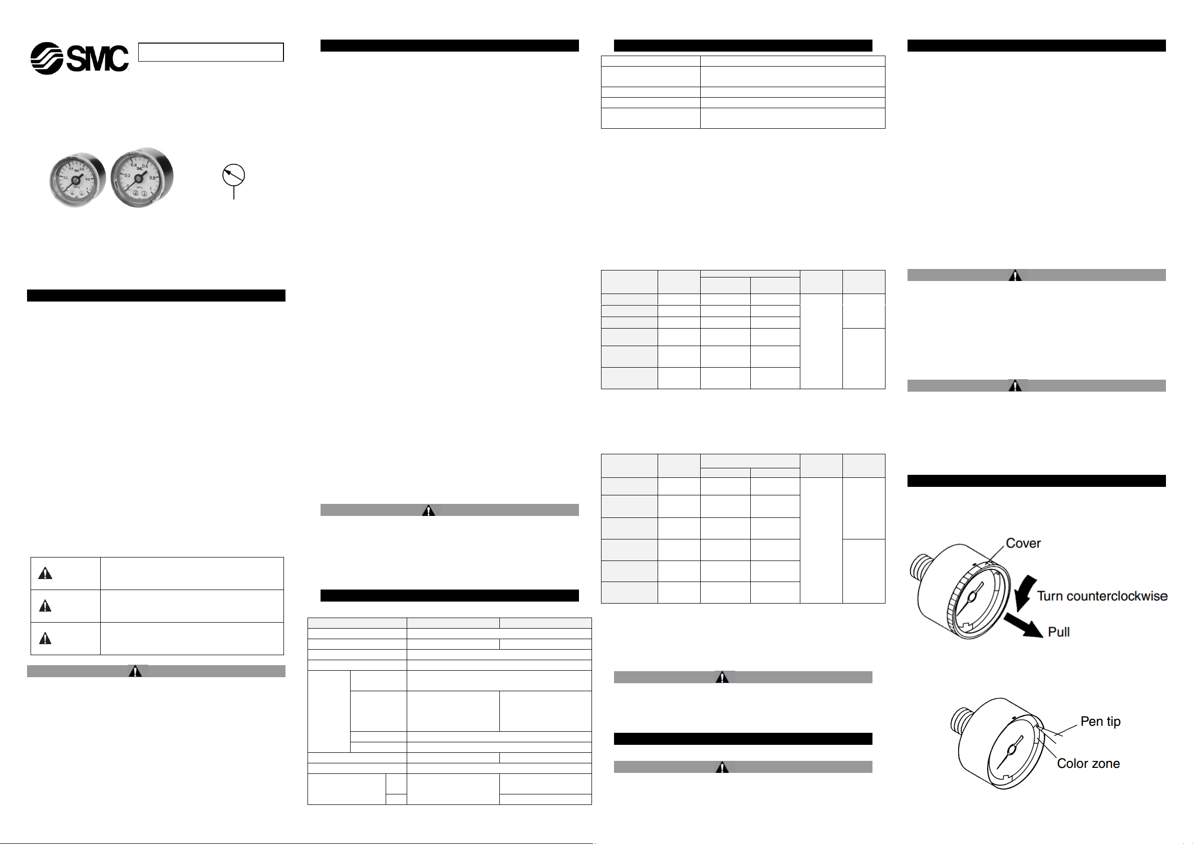
4.1 Procedure for Setting the Limit Gauge Indicator
1) Before setting the colour zone (red), turn the cover counter clockwise
(approximately 6 to 7 mm) until it stops. Then remove by pulling it
towards you.
2) Use a pen tip to set the colour zone (red). Be careful not to bend the
other needle or damage the dial plate.
Page 1 of 2
Page 2
G**-SMV03EN
AUSTRIA
SMC Pneumatik GmbH,Girakstrasse 8, AT-2100
Korneuburg, Austria
BELGIUM
SMC Pneumatics N.V. ⁄ S.A. Nijverheidsstraat 20, B-2160
Wommelgem, Belgium
BULGARIA
SMC Industrial Automation Bulgaria EOOD, Business
Park Sofia, Building 8-6th floor, BG-1715 Sofia, Bulgaria
CROATIA
SMC IndustrijskaAutomatikad.o.o. ZagrebačkaAvenija
104,10 000 Zagreb
CZECH REP.
SMC Industrial Automation CZ s.r.o. Hudcova 78a, CZ61200 Brno, Czech Republic
DENMARK
SMC Pneumatik A ⁄ S,Egeskovvej 1, DK-8700 Horsens,
Denmark
ESTONIA
SMC Pneumatics Estonia Oü,Laki 12, EE-10621 Tallinn,
Estonia
FINLAND
SMC Pneumatics Finland Oy, PL72, Tiistinniityntie 4, SF02031 Espoo, Finland
FRANCE
SMC France, 1, Boulevard de Strasbourg, Parc Gustave
Eiffel, Bussy Saint Georges, F-77607 Marne La
ValleeCedex 3, France
GERMANY
SMC Pneumatik GmbH, Boschring 13-15, 63329
Egelsbach, Germany
GREECE
SMC Italia Hellas Branch, Anagenniseos 7-9-P.C. 14342
N.Philadelphia, Athens, Greece
HUNGARY
SMC Hungary IpariAutomatizálásiKft.Torbágy u. 19, HU2045 Törökbálint, Hungary
IRELAND
SMC Pneumatics (Ireland) Ltd.2002 Citywest Business
Campus, Naas Road, Saggart, Co. Dublin, Ireland
ITALY
SMC Italia S.p.A.Via Garibaldi 62, I-20061Carugate,
(Milano), Italy
LATVIA
SMC Pneumatics Latvia SIA, Dzelzavas str. 120g, Riga,
LV-1021, Latvia
LITHUANIA
UAB “SMC Pneumatics”, Oslo g. 1, LT-04123 Vilnius,
Lithuania
NETHERLANDS
SMC Pneumatics B.V.De Ruyterkade 120, NL-1011 AB
Amsterdam, the Netherlands
NORWAY
SMC Pneumatics Norway AS, Vollsveien 13 C,
GranfosNæringspark, N-1366 Lysaker, Norway
POLAND
SMC Industrial Automation, Polska Sp z o.o.
02-826 Warszawa, ul. Poloneza 89
PORTUGAL
SMC España S.A. Zuazobidea 14, 01015 Vitoria, Spain
ROMANIA
SMC Romania S.r.l. StrFrunzei 29, Sector 2, Bucharest,
Romania
RUSSIA
SMC Pneumatik LLC. Business centre, building 3, 15
Kondratjevskij prospect, St.Petersburg, Russia, 195197
SLOVAKIA
SMC PriemyselnáAutomatizáciaSpols.r.o. Fantranská
1223, Teplickanadvahom, 01301, Slovakia
SLOVENIA
SMC IndustrijskaAvtomatikad.o.o. Mirnskacesta 7, SLO8210 Trebnje, Slovenia
SPAIN
SMC España S.A. Zuazobidea 14, 01015 Vitoria, Spain
SWEDEN
SMC Pneumatics Sweden AB,Ekhagsvägen 29-31, SE141 71 Segeltorp, Sweden
SWITZERLAND
SMC Pneumatik AG,Dorfstrasse 7, Postfach, 8484
Weisslingen, Switzerland
TURKEY
SMC PnömatikSanayiTicaretveServis A.Ş.
GülbaharCaddesi, Aydın Plaza, No: 9 ⁄ 4 Güneşli –
34212 , Istanbul
UK
SMC Pneumatics (U.K.) Ltd. Vincent Avenue, Crownhill,
Milton Keynes, Buckinghamshire MK8 0AN, United
Kingdom
URL :
http// www.smcworld.com (Global) http// www.smceu.com (Europe)
G 36 – 10 – 01 – L – –
Pressure gauge
Color zone type
Symbol
❶
Size
G36
G46
● ● ● ● ● ● ○
(2) ○ (2) ○ (2)
○
(2)
○
(2)
○
(2)
Pressure
2
0.2 MPa
4
0.4 MPa
10
1.0 MPa
P2
(1)
0.2 MPa, 30 psi
P4
(1)
0.4 MPa, 60 psi
P10
(1)
1.0 MPa, 150 psi
thread
01
R 1/8
02
R 1/4
material
Nil
Polycarbonate
N
Nylon
Nil
Without cover ring assy
C
Clear cover has no
protrusion (irremovable)
C1
Clear cover has protrusion
(removable)
ation
Nil
-
X2
Stud parts nickel plated
X30
Both MPa and psi
●
●
-
●
●
●
●
●
-
●
-
●
-
●
●
●
●
-
○
(2)
○
(2)
❷
❸ ❹ ❺
❻
G36-□□-01-L(N)
G46-□□-01 to 02-L(N)
G46-□□-01 to 02-L(N)-C
G46-□□-01 to 02-L(N)–C1
With cover ring assembly
(For panel mount)
Type C
(Clear cover is not removable.)
Type C1
(Clear cover is removable.)
Panel fitting dimensions
Plate thickness Max. 3.5 t
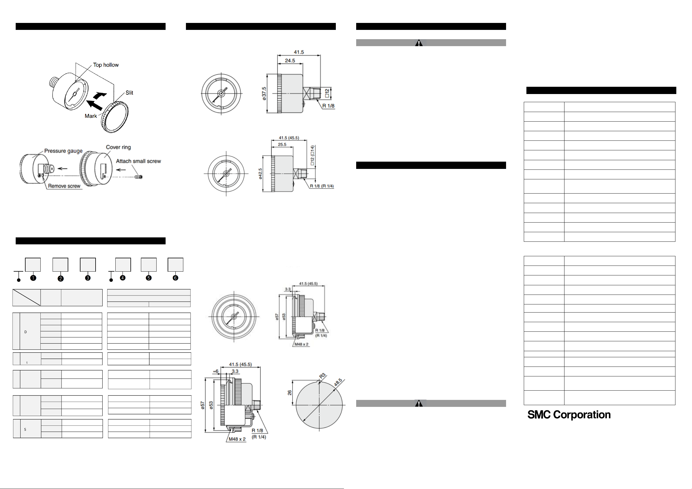
4 Settings - continued
3) After completing the setting, replace the cover. Fit the cover by
aligning the cut-out in the cover to the groove on the top of the black
case. Turn the cover clockwise (approximately 6 to 7 mm) until it
stops. Make sure that the matching mark on the cover is aligned with
the groove on the top of the case.
4.2 Procedure for Assembling the Cover Ring Assembly
1) Remove the small screw (1 position) from the pressure gauge.
2) Place the cover ring on the pressure gauge.
3) Using the small screw that is provided with the cover ring, install the
cover ring. The installation torque is 0.3 to 0.5 N.m.
5 How to Order
6 Outline Dimensions (mm)
7 Maintenance
7.1 General Maintenance
Caution
Not following proper maintenance procedures could cause the
product to malfunction and lead to equipment damage.
If handled improperly, compressed air can be dangerous.
Maintenance of pneumatic systems should be performed only by
qualified personnel.
Before performing maintenance, turn off the power supply and be
sure to cut off the supply pressure. Confirm that the air is released to
atmosphere.
After installation and maintenance, apply operating pressure and
9 Contacts
power to the equipment and perform appropriate functional and
leakage tests to make sure the equipment is installed correctly.
If any electrical connections are disturbed during maintenance,
ensure they are reconnected correctly and safety checks are carried
out as required to ensure continued compliance with applicable
national regulations.
Do not make any modification to the product.
Do not disassemble the product, unless required by installation or
maintenance instructions.
8 Limitations of Use
8.1 Limited warranty and Disclaimer/Compliance Requirements
The product used is subject to the following “Limited warranty
and Disclaimer” and “Compliance Requirements”. Read and
accept them before using the product.
Limited warranty and Disclaimer
1) The warranty period of the product is 1 year in service or 1.5 years
after the product is delivered, whichever is first
(1)
. Also, the product
may have specified durability, running distance or replacement parts.
Please consult your nearest sales branch.
Description
Max.
Display
Connection
Clear
cover
Attach-
ment
Special
Specific-
Note 1) This symbol must be used with Special specification “X30.”
Note 2) Under the New Measurement Law, products for overseas use
only (SI unit type for use in Japan)
2) For any failure or damage reported within the warranty period
which is clearly our responsibility, a replacement product or
necessary parts will be provided.
This limited warranty applies only to our product independently, and
not to any other damage incurred due to the failure of the product.
3) Prior to using SMC products, please read and understand the
warranty terms and disclaimers noted in the specified catalogue for
the particular products.
(1)
Vacuum pads are excluded from this 1 year warranty.
A vacuum pad is a consumable part, so it is warranted for a year after
it is delivered. Also, even within the warranty period, the wear of a
product due to the use of the vacuum pad or failure due to the
deterioration of rubber material are not covered by the limited
warranty.
Compliance Requirements
1) The use of SMC products with production equipment for the
manufacture of weapons of mass destruction (WMD) or any other
weapon is strictly prohibited.
2) The exports of SMC products or technology from one country to
another are governed by the relevant security laws and regulations of
the countries involved in the transaction. Prior to the shipment of a
SMC product to another country, assure that all local rules governing
that export are known and followed.
Caution
SMC products are not intended for use as instruments for legal
metrology.
Measurement instruments that SMC manufactures or sells have not
been qualified by type approval tests relevant to the metrology
(measurement) laws of each country.
Therefore, SMC products cannot be used for business or certification
ordained by the metrology (measurement) laws of each country.
'SMC Corporation, Akihabara UDX15F, 4-14-1, Sotokanda, Chiyoda-ku, Tokyo
101 0021
Specifications are subject to change without prior notice from the manufacturer.
© 2017 SMC Corporation All Rights Reserved.
Template DKP50047-F-085E
Page 2 of 2
 Loading...