

Page 1
Document Revision: 1.D
T18627
FieldServer
QuickServer Start-up Guide
FS-QS-2X10
APPLICABILITY & EFFECTIVITY
Effective for all systems manufactured after March 2019.
Page 2

QuickServer Start-Up Guide
Contact Information
Technical Support
Please call us for any technical support needs related to the FieldServer product.
Sierra Monitor Corporation
1991 Tarob Court
Milpitas, CA 95035
Website: www.sierramonitor.com
U.S. Support Information:
+1 408 964-4443
+1 800 727-4377
Email: support@sierramonitor.com
EMEA Support Information:
+31 33 808 0590
Email: support.emea@sierramonitor.com
Page 3

QuickServer Start-Up Guide
Table of Contents
TABLE OF CONTENTS
1 QuickServer Description ..................................................................................................................... 6
2 Certifications ........................................................................................................................................ 6
2.1 BTL Mark – BACnet Testing Laboratory......................................................................................... 6
3 Supplied Equipment ............................................................................................................................ 6
4 QuickServer Setup ............................................................................................................................... 7
4.1 Mounting ......................................................................................................................................... 7
4.2 DIP Switch Settings ........................................................................................................................ 8
4.2.1 Bias Resistors.......................................................................................................................... 8
4.2.2 Termination Resistor ............................................................................................................... 9
4.3 Connecting the R1 Port ................................................................................................................ 10
4.3.1 Wiring .................................................................................................................................... 10
4.3.2 Supported RS-485 Baud Rates by Protocol .......................................................................... 10
4.4 Power Up the Device .................................................................................................................... 11
5 Connect the PC to the QuickServer ................................................................................................. 12
5.1 Connecting to the Gateway via Ethernet ...................................................................................... 12
5.1.1 Enable Access Through the Local Browser .......................................................................... 12
5.1.1.1 Changing the Subnet of the Connected PC ................................................................... 12
5.1.1.2 Changing the IP Address of the QuickServer with FieldServer Toolbox ....................... 13
5.1.2 Using the FS-GUI to Set the IP Address ............................................................................... 14
5.1.3 Accessing SMC Cloud ........................................................................................................... 14
6 Configuring the QuickServer ............................................................................................................ 15
6.1 Retrieve the Sample Configuration File ........................................................................................ 15
6.2 Change the Configuration File to Meet the Application ................................................................ 15
6.3 Load the Updated Configuration File ............................................................................................ 16
6.3.1 Using the Toolbox Application to Load a Configuration File ................................................. 16
6.3.2 Using the FS-GUI to Load a Configuration File ..................................................................... 17
6.3.3 Retrieve the Configuation File for Modification or Backup .................................................... 18
6.4 Test and Commission the QuickServer ........................................................................................ 19
Appendix A Useful Features .................................................................................................................... 20
Appendix A.1. SSL/TLS for Secure Connection ...................................................................................... 20
Appendix A.1.1. Configuring FieldServer as a SSL/TLS Server ......................................................... 20
Appendix A.1.1.1. Simple Secure Server Configuration ................................................................. 20
Appendix A.1.1.2. Limiting Client Access ....................................................................................... 21
Appendix A.1.1.3. To Upload the Authority File to the FieldServer ................................................ 21
Appendix A.1.1.4. Certificate Validation Options ............................................................................ 22
Appendix A.1.1.5. Set up Server Certificate ................................................................................... 22
Appendix A.1.2. Configuring FieldServer as SSL/TLS Client .............................................................. 23
Appendix A.1.2.1. Simple Secure Client Configuration .................................................................. 23
Appendix A.1.2.2. Limit Server Access ........................................................................................... 23
Appendix A.1.2.3. Certificate Validation Options ............................................................................ 23
Appendix A.1.2.4. Set up Client Certificate ..................................................................................... 23
Appendix B Troubleshooting ................................................................................................................... 24
Appendix B.1. Communicating with the QuickServer Over the Network ................................................ 24
Appendix B.2. Regarding Subnets and Subnet Masks ........................................................................... 24
Appendix B.3. Before Contacting Technical Support Take a Diagnostic Capture .................................. 25
Appendix B.3.1. Using the FieldServer Toolbox .................................................................................. 25
Appendix B.3.2. Using FS-GUI ............................................................................................................ 28
Appendix B.4. LED Functions ................................................................................................................. 29
Appendix B.5. Securing QuickServer with Password .............................................................................. 30
Appendix B.6. Factory Reset Instructions ............................................................................................... 30
Page 4

QuickServer Start-Up Guide
Table of Contents
Appendix C Reference .............................................................................................................................. 31
Appendix C.1. QuickServer FS-QS-2X10-XXXX DCC ............................................................................ 31
Appendix C.2. QuickServer Part Numbers .............................................................................................. 31
Appendix C.3. Compliance with UL Regulations ..................................................................................... 32
Appendix C.4. Dimension Drawing FS-QS-2X10-XXXX ......................................................................... 32
Appendix C.5. Specifications ................................................................................................................... 33
Appendix D Limited 2 Year Warranty ...................................................................................................... 34
Page 5

QuickServer Start-Up Guide
List of Figures
LIST OF FIGURES
Figure 1: DIN Rail Bracket ............................................................................................................................ 7
Figure 2: DIN Rail Mounted........................................................................................................................... 7
Figure 3: Bias Resistor DIP Switches ........................................................................................................... 8
Figure 4: Termination Resistor DIP Switch ................................................................................................... 9
Figure 5: R1 & R2 Connection Ports ........................................................................................................... 10
Figure 6: Required Current Draw for the Gateway ..................................................................................... 11
Figure 7: Power Connections ...................................................................................................................... 11
Figure 8: Ethernet Port Location ................................................................................................................. 12
Figure 9: FS-GUI Network Settings ............................................................................................................ 14
Figure 10: FS-GUI File Transfer.................................................................................................................. 15
Figure 11: FS-GUI Loading Files ................................................................................................................ 17
Figure 12: Retrieve Configuration File ........................................................................................................ 18
Figure 13: FS-GUI Connections Page ........................................................................................................ 19
Figure 14: Ethernet Port Location ............................................................................................................... 25
Figure 15: Diagnostic LEDs ........................................................................................................................ 29
Figure 16: FS-GUI Passwords Page ........................................................................................................... 30
Figure 17: Password Recovery Page ......................................................................................................... 30
Figure 18: QuickServer Dimension Drawing ............................................................................................... 32
Figure 19: Specifications ............................................................................................................................. 33
Page 6
QuickServer Start-Up Guide
Page 6 of 34
1 QUICKSERVER DESCRIPTION
QuickServer is a high performance, cost effective Building and Industrial Automation multi-protocol
gateway providing protocol translation between serial/Ethernet devices and networks.
NOTE: For troubleshooting assistance refer to Appendix B, or any of the troubleshooting
appendices in the related driver supplements. Check the Sierra Monitor website for
technical support resources and documentation that may be of assistance.
The QuickServer is cloud ready and connects with Sierra Monitor’s SMC Cloud. See Section 5.1.3 for
further information.
2 CERTIFICATIONS
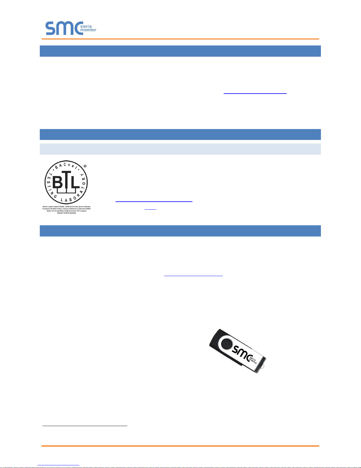
2.1 BTL Mark – BACnet1 Testing Laboratory
3 SUPPLIED EQUIPMENT
QuickServer Gateway
• Preloaded with two selected drivers. A sample configuration file is also loaded.
• All instruction manuals, driver manuals, support utilities are available on the USB drive provided
in the optional accessory kit, or on the Sierra Monitor website.
Accessory kit (optional) (Part # FS-8915-38-QS) includes:
• 7-ft Cat-5 cable with RJ45 connectors at both ends
• Power Supply -110/220V (p/n 69196)
• Screwdriver for connecting to terminals
• USB Flash drive loaded with:
o QuickServer 2X10 Start-up Guide
o FieldServer Configuration Manual
o All FieldServer Driver Manuals
o Support Utilities
o Any additional folders related to special files
configured for a specific QuickServer
o Additional components as required - see driver manual supplement for details
1
BACnet is a registered trademark of ASHRAE.
The BTL Mark is a symbol that indicates that a product has passed a series of
rigorous tests conducted by an independent laboratory which verifies that the
product correctly implements the BACnet features claimed in the listing. The mark is
a symbol of a high-quality BACnet product.
Go to www.BACnetInternational.net for more information about the BACnet Testing
Laboratory. Click here for the BACnet PIC Statement.
Page 7
QuickServer Start-Up Guide
Page 7 of 34
4 QUICKSERVER SETUP
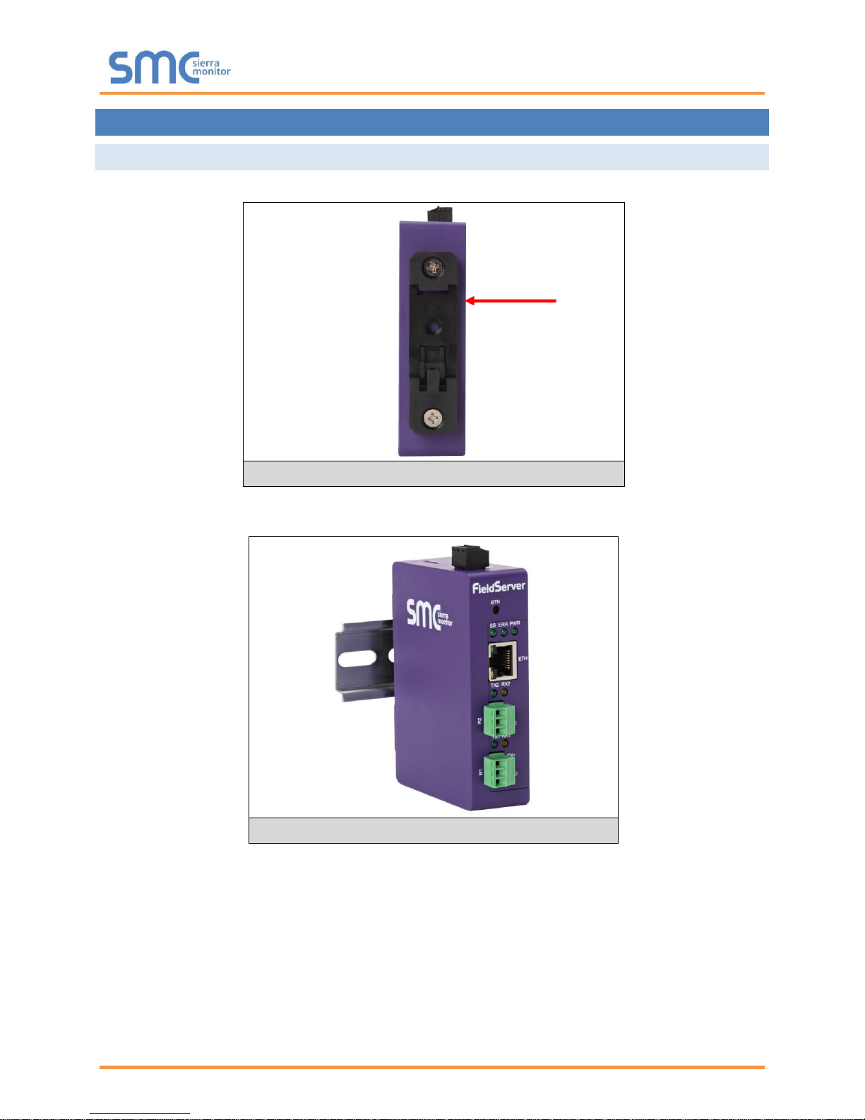
4.1 Mounting
The QuickServer can be mounted using the DIN rail mounting bracket on the back of the unit.
NOTE: For dimension details see Appendix C.4.
Figure 1: DIN Rail Bracket
Figure 2: DIN Rail Mounted
Din Rail
Bracket
Page 8
QuickServer Start-Up Guide
Page 8 of 34
4.2 DIP Switch Settings
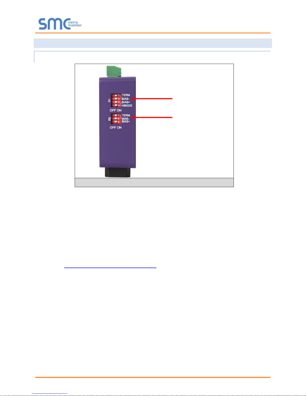
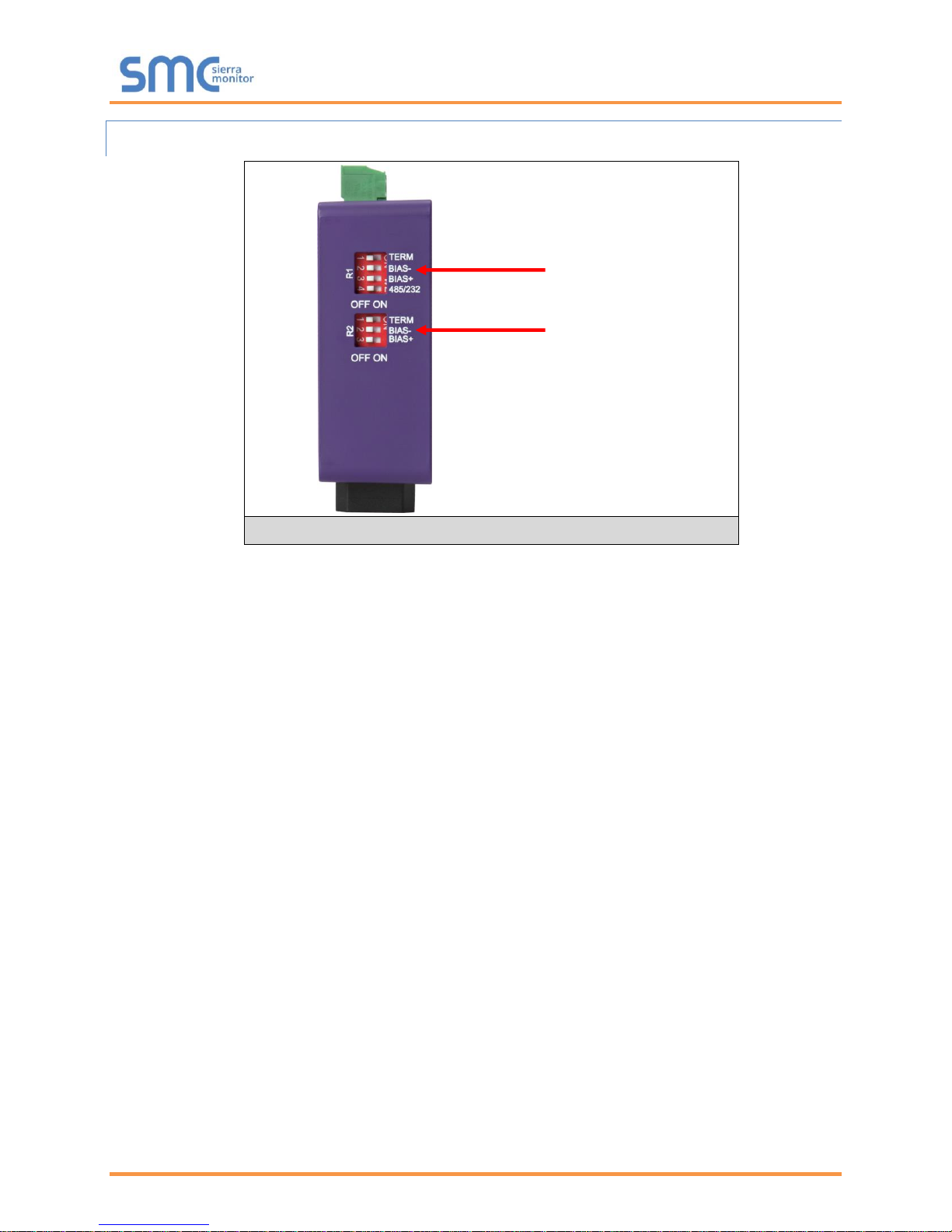
4.2.1 Bias Resistors
To enable Bias Resistors, move both the BIAS- and BIAS+ dip switches to the right in the
orientation shown in Figure 3.
The QuickServer bias resistors are used to keep the RS-485 bus to a known state, when there is no
transmission on the line (bus is idling), to help prevent false bits of data from being detected. The bias
resistors typically pull one line high and the other low - far away from the decision point of the logic.
The bias resistor is 510 ohms which is in line with the BACnet spec. It should only be enabled at one
point on the bus (for example, on the field port were there are very weak bias resistors of 100k). Since
there are no jumpers, many QuickServers can be put on the network without running into the bias resistor
limit which is < 500 ohms.
NOTE: See www.ni.com/support/serial/resinfo.htm for additional pictures and notes.
NOTE: The R1 and R2 DIP Switches apply settings to the respective serial port.
NOTE: If the gateway is already powered on, DIP switch settings will not take effect unless the
unit is power cycled.
R1 Bias Resistor DIP
Switches (2 and 3)
Figure 3: Bias Resistor DIP Switches
R2 Bias Resistor DIP
Switches (2 and 3)
Page 9
QuickServer Start-Up Guide
Page 9 of 34
4.2.2 Termination Resistor
If the QuickServer is the last device on the serial trunk, then the End-Of-Line Termination Switch needs to
be enabled. To enable the Termination Resistor, move the TERM dip switch to the right in the
orientation shown in Figure 4.
Termination resistor is also used to reduce noise. It pulls the two lines of an idle bus together. However,
the resistor would override the effect of any bias resistors if connected.
NOTE: The R1 and R2 DIP Switches apply settings to the respective serial port.
NOTE: If the gateway is already powered on, DIP switch settings will not take effect unless the
unit is power cycled.
Figure 4: Termination Resistor DIP Switch
R1 Termination
Resistor DIP Switch (1)
R2 Termination
Resistor DIP Switch (1)
Page 10
QuickServer Start-Up Guide
Page 10 of 34
4.3 Connecting the R1 Port
For the R1 Port only: Switch between RS-485 and RS-232 by moving the number 4 DIP Switch left for
RS-485 and right for RS-232 (Figure 4).
The R2 Port is RS-485.
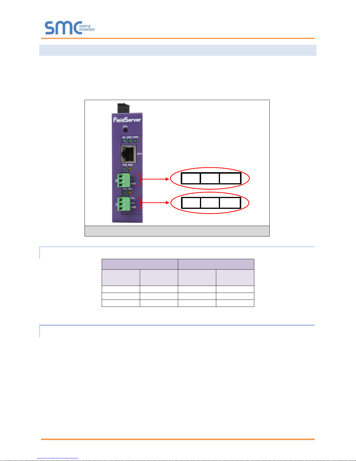
Connect to the 3-pin connector(s) as shown below.
4.3.1 Wiring
RS-485
RS-232
BMS RS-485
Wiring
Gateway Pin
Assignment
BMS RS-232
Wiring
Gateway Pin
Assignment
RS-485 +
TX +
RS-232 -
TX +
RS-485 -
RX -
RS-232 +
RX -
GND
GND
GND
GND
NOTE: Use standard grounding principles for GND.
4.3.2 Supported RS-485 Baud Rates by Protocol
The supported baud rates for either port is based on the protocol of the connected devices.
The following baud rates are supported for Modbus RTU:
2400, 4800, 9600, 19200, 38400, 57600, 76800, 115200
The following baud rates are supported for BACnet MS/TP:
9600, 19200, 38400, 76800
Figure 5: R1 & R2 Connection Ports
TX+ RX- GND
+ - GND
Page 11
QuickServer Start-Up Guide
Page 11 of 34
4.4 Power Up the Device
Check power requirements in the table below:
Power Requirement for External Gateway
Current Draw Type
QuickServer Family
12VDC
24V DC/AC
FS-QS-2X10-XXXX (Typical)
250mA
125mA
NOTE: These values are ‘nominal’ and a safety margin should be added to the power supply of
the host system. A safety margin of 25% is recommended.
Figure 6: Required Current Draw for the Gateway
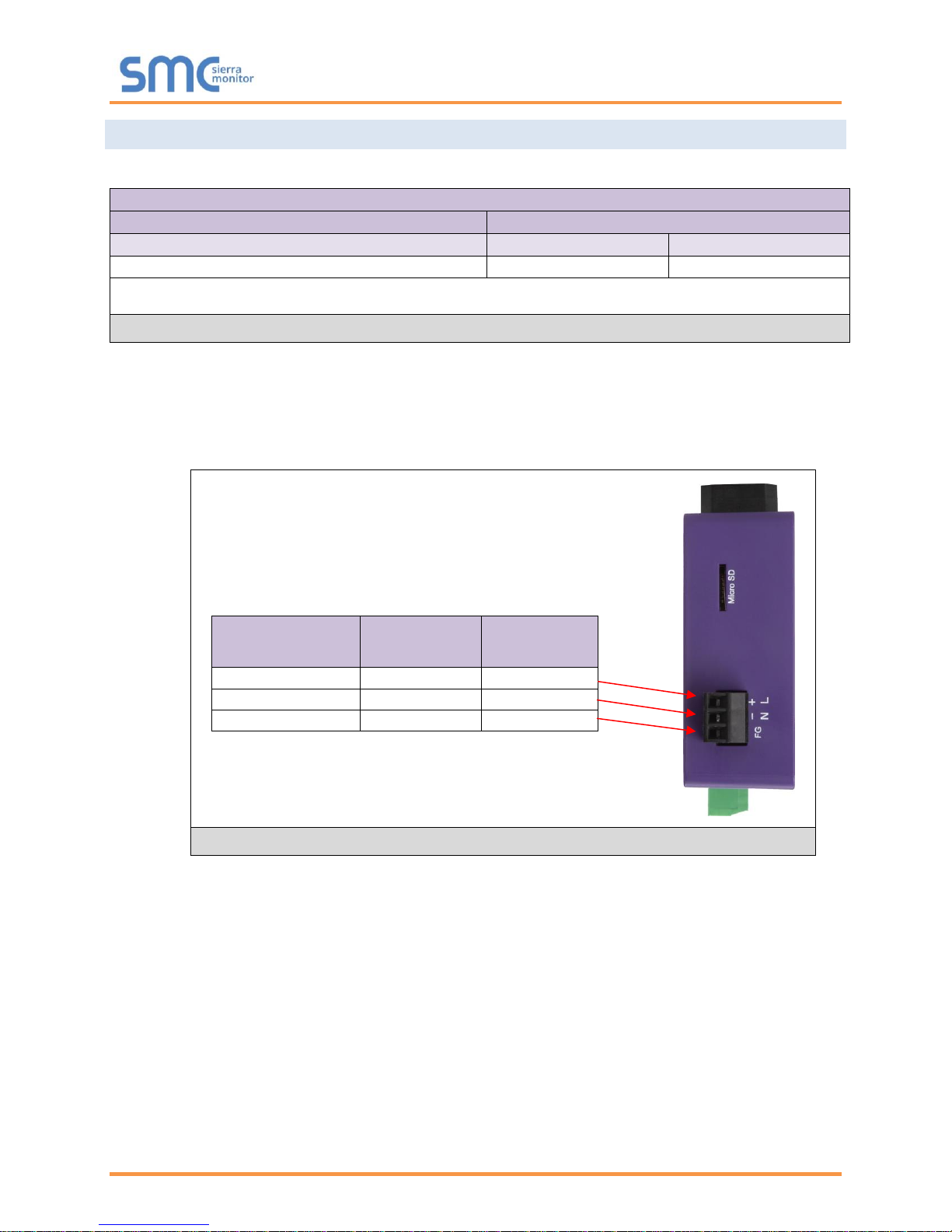
Apply power to the QuickServer as shown below in Figure 7. Ensure that the power supply used
complies with the specifications provided in Appendix C.5.
• The gateway accepts 12-24VDC or 24VAC on pins 4 and 5.
• Frame GND should be connected.
Power to
Gateway
Gateway
Pin #
Pin
Assignment
Power In (+)
Pin 4
V +
Power In (-)
Pin 5
V -
Frame Ground
Pin 6
FRAME GND
Figure 7: Power Connections
Page 12

QuickServer Start-Up Guide
Page 12 of 34
5 CONNECT THE PC TO THE QUICKSERVER
5.1 Connecting to the Gateway via Ethernet
First, connect a Cat-5 Ethernet cable (straight through or cross-over) between the local PC and the
QuickServer.
5.1.1 Enable Access Through the Local Browser
There are two methods to enable access to the QuickServer in the local browser, either by
changing the subnet of the connected PC (Section 5.1.1.1) or using the FieldServer Toolbox to
change the IP Address of the QuickServer (Section 5.1.1.2).
NOTE: Only perform one method or the other.
5.1.1.1 Changing the Subnet of the Connected PC
The default IP Address for the QuickServer is 192.168.2.101, Subnet Mask is 255.255.255.0. If the PC
and QuickServer are on different IP networks, assign a static IP Address to the PC on the 192.168.1.xxx
network.
For Windows 10:
• Find the search field in the local computer’s taskbar (usually to the right of the windows icon )
and type in “Control Panel”.
• Click “Control Panel”, click “Network and Internet” and then click “Network and Sharing Center”.
• Click “Change adapter settings” on the left side of the window.
• Right-click on “Local Area Connection” and select “Properties” from the dropdown menu.
• Highlight and then click the Properties button.
• Select and enter a static IP Address on the same subnet. For example:
• Click the Okay button to close the Internet Protocol window and the Close button to close the
Ethernet Properties window.
Ethernet Port
Figure 8: Ethernet Port Location
Page 13

QuickServer Start-Up Guide
Page 13 of 34
5.1.1.2 Changing the IP Address of the QuickServer with FieldServer Toolbox
• Ensure that FieldServer Toolbox is loaded onto the local PC. Otherwise, download the
FieldServer-Toolbox.zip via the Sierra Monitor website’s Software Downloads.
• Extract the executable file and complete the installation.
• Double click on the FS Toolbox Utility and click Discover Now on the splash page.
• Find the desired gateway and click the Configure Device button (gear icon) to the right of the
gateway information.
NOTE: If connectivity status is green, then the IP Address doesn’t need to be changed (the
gateway is already on the same subnet). Skip the rest of the section.
• Select Network Settings in the Configure Device window.
• Modify the IP Address (N1 IP Address field) of the gateway Ethernet port.
Change additional fields as needed
NOTE: If the gateway is connected to a router, the Default Gateway field of the gateway should be
set to the IP Address of the connected router.
NOTE: Do not change the DHCP Server State (N1 DHCP Server State field).
NOTE: If DNS settings are unknown, set DNS1 to “8.8.8.8” and DNS2 to “8.8.4.4”.
• Click Update IP Settings, then click the “Change and restart” button to reboot the Gateway and
activate the new IP Address. See the FieldServer Toolbox and GUI Manual for more information.
Page 14

QuickServer Start-Up Guide
Page 14 of 34
5.1.2 Using the FS-GUI to Set the IP Address
• From the FS-GUI main home page, click on setup and then Network Settings to enter the Edit IP
Address Settings menu.
• Modify the IP Address (N1 IP Address field) of the QuickServer Ethernet port.
• If necessary, change the Netmask (N1 Netmask field).
• Type in a new Subnet Mask.
• If necessary, change the IP Gateway (Default Gateway field).
• Type in a new IP Gateway.
NOTE: If the FieldServer is connected to a router, the IP Gateway of the FieldServer should be set
to the same IP Address of the router.
• Click Update IP Settings, then click on the System Restart to restart the Gateway and activate the
new IP Address.
NOTE: If the FS-GUI was open in a browser, the browser will need to be pointed to the new IP
Address of the QuickServer before the FS-GUI will be accessible again.
5.1.3 Accessing SMC Cloud
The FieldPoP™ button (see Figure 9) allows users to connect to the SMC Cloud, Sierra
Monitor’s device cloud solution for IIoT. The SMC Cloud enables secure remote connection to field
devices through a FieldServer and its local applications for configuration, management, maintenance. For
more information about the SMC Cloud, refer to the SMC Cloud Start-up Guide.
Figure 9: FS-GUI Network Settings
Page 15

QuickServer Start-Up Guide
Page 15 of 34
6 CONFIGURING THE QUICKSERVER
6.1 Retrieve the Sample Configuration File
The configuration of the QuickServer is provided to the QuickServer’s operating system via a commadelimited file called “CONFIG.CSV”.
If a custom configuration was ordered, the QuickServer will be programmed with the relevant device
registers in the Config.csv file for the initial start-up. If not, the product is shipped with a sample config.csv
that shows an example of the drivers ordered.
• In the main menu of the FS-GUI screen, go to “Setup”, then “File Transfer”, and finally “Retrieve”.
• Click on “config.csv”, and open or save the file.
6.2 Change the Configuration File to Meet the Application
Refer to the FieldServer Configuration Manual in conjunction with the Driver supplements for information
on configuring the QuickServer.
Figure 10: FS-GUI File Transfer
Page 16

QuickServer Start-Up Guide
Page 16 of 34
6.3 Load the Updated Configuration File
6.3.1 Using the Toolbox Application to Load a Configuration File
• From the Toolbox main page, click on the setup icon (the gear picture).
• Select File Transfer.
• Browse and select the .csv file, open, then click “Update Config”.
• Once download is complete, click the Restart Button (or cycle power to the QuickServer) to put
the new file into operation.
NOTE: It is possible to do multiple downloads to the QuickServer before resetting it.
Page 17

QuickServer Start-Up Guide
Page 17 of 34
6.3.2 Using the FS-GUI to Load a Configuration File
• In the main menu of the FS-GUI screen, click “Setup”, then “File Transfer” and finally “Update”.
• Browse and select the .csv file, open, then click “Submit”.
• Once download is complete, a message bar will appear confirming that the configuration was
updated successfully.
• Click the System Restart Button to put the new file into operation.
NOTE: It is possible to do multiple downloads to the QuickServer before resetting it.
Figure 11: FS-GUI Loading Files
Page 18

QuickServer Start-Up Guide
Page 18 of 34
6.3.3 Retrieve the Configuation File for Modification or Backup
To get a copy of the configuration file for modifying or backing up a configuration on a local computer, do
the following:
• In the main menu of the FS-GUI screen, click “Setup”, then “File Transfer”.
• Click the “config.csv” link under the “Retrieve” heading in the middle section of the screen.
o The file will automatically download to the web browser’s default download location.
• Edit or store the file as desired.
NOTE: Before using any backup configuration file to reset the configuration settings, check that
the backup file is not an old version.
Figure 12: Retrieve Configuration File
Page 19

QuickServer Start-Up Guide
Page 19 of 34
6.4 Test and Commission the QuickServer
• Connect the QuickServer to the third party device(s), and test the application.
• From the landing page of the FS-GUI click on “View” in the navigation tree, then “Connections” to
see the number of messages on each protocol.
Figure 13: FS-GUI Connections Page
Page 20

QuickServer Start-Up Guide
Page 20 of 34
Appendix A Useful Features
Appendix A.1. SSL/TLS for Secure Connection
SSL/TLS (Secure Sockets Layer/Transport Layer Security) is a security technology for establishing an
encrypted connection between a server and a client. This allows the secure transfer of data across
untrusted networks.
Appendix A.1.1. Configuring FieldServer as a SSL/TLS Server
The following example sets the FieldServer to accept a secure Modbus/TCP connection on port 1502.
Appendix A.1.1.1. Simple Secure Server Configuration
Add TLS_Port parameter in the connections section of the configuration file and set to a port number
between 1 – 65535.
Connections
Adapter , Protocol , TLS_Port
N1 , Modbus/TCP , 1502
This configuration sets the FieldServer to accept any incoming connection but will not request a client’s
certificate for verification. This means that the FieldServer end point communication will be encrypted but
not authenticated.
The FieldServer will send an embedded self-signed certificate if one is requested by a connecting client.
NOTE: If a remote client requires a certificate, then request the smc_cert.pem certificate from
Sierra Monitor Technical Support and update the remote client’s authority as per vendor
instructions.
Page 21

QuickServer Start-Up Guide
Page 21 of 34
Appendix A.1.1.2. Limiting Client Access
In addition to TLS_Port parameter also add Validate_Client_Cert in the connections section of the
configuration file and set it to “Yes”.
Connections
Adapter , Protocol , TLS_Port , Validate_Client_Cert
N1 , Modbus/TCP , 1502 , Yes
The configuration above sets the FieldServer to request and verify a client’s certificate against its internal
authority file before accepting connection. By default, this means the FieldServer will only accept
connections from other FieldServers.
In order to load an authority file so that the FieldServer will accept connections from a chosen list of
remote clients, configure the FieldServer with the following connection settings:
Connections
Adapter , Protocol , TLS_Port , Validate_Client_Cert , Cert_Authority_File
N1 , Modbus/TCP , 1502 , Yes , my_authorized_clients.pem
This configuration has the FieldServer accept connections from clients who have the correct certificate.
The authority file is a collection of client certificates in PEM format. This file can be edited using any text
file editor.
NOTE: Cert_Authority_File is useful only if Validate_Client_Cert is set to ‘Yes’.
Appendix A.1.1.3. To Upload the Authority File to the FieldServer
1. Enter the IP address of the FieldServer into a web browser.
2. Choose the ‘Setup’ option in the Navigation Tree and Select ‘File Transfer’.
3. Choose the ‘General’ tab.
4. Click on the ‘Browse’ button and select the PEM file you want to upload.
5. Click on ‘Submit’.
6. When the message, “The file was uploaded successfully” appears, click on the ‘System Restart’
button.
Page 22

QuickServer Start-Up Guide
Page 22 of 34
Appendix A.1.1.4. Certificate Validation Options
If connections must be limited to only a particular domain (vendor devices), include Check_Remote_Host
to specify the domain/host name.
Connections
Adapter , Protocol , TLS_Port , Validate_Client_Cert , Cert_Authority_File , Check_Remote_Host
N1 , Modbus/TCP , 1502 , Yes , my_authorized_clients.pem , SMC
The configuration above tells the FieldServer to only accept connections that have the correct certification
and is coming from the specified host.
The Check_Remote_Host value is synonymously known as common name, host name or domain etc.
The common name can be obtained by the following methods:
• Ask the certificate issuer for the host name.
• Use online tools to decode the certificate (for example: https://www.sslshopper.com/certificate-
decoder.html).
• If the program openssl is installed on the local PC, then run the following command to get the
common name: openssl x509 -in certificate.pem -text -noout
Appendix A.1.1.5. Set up Server Certificate
Make sure the certificate is in PEM format. Otherwise, convert it to PEM format (reference the link below).
support.ssl.com/Knowledgebase/Article
Configure the FieldServer to use a custom certificate as shown below:
Connections
Adapter , Protocol , TLS_Port , Server_Cert_File
N1 , Modbus/TCP , 1502 , my_server_cert.pem
Page 23

QuickServer Start-Up Guide
Page 23 of 34
Appendix A.1.2. Configuring FieldServer as SSL/TLS Client
The following Node configurations set the FieldServer to open a secure Modbus/TCP connection to
Server at IP Address 10.11.12.13 on port 1502.
Appendix A.1.2.1. Simple Secure Client Configuration
Add Remote_Node_TLS_Port parameter in the nodes section of the configuration file and set to a port
number between 1 – 65535.
Nodes
Node_Name , Node_ID , Protocol , Adapter , IP_Address , Remote_Node_TLS_Port
PLC_11 , 11 , Modbus/TCP , N1 , 10.11.12.13 , 1502
The above configuration sets the FieldServer to connect to a remote server but does not request a
server’s certificate for verification. This means that the FieldServer end point communication will be
encrypted but not authenticated.
If requested by a remote server, the FieldServer will send an embedded self-signed certificate.
Appendix A.1.2.2. Limit Server Access
Add the Validate_Server_Cert parameter to the client node section of the configuration.
……. , Remote_Node_TLS_Port , Validate_Server_Cert
…….. , 1502 , Yes
The above configuration sets the FieldServer to request and verify the server’s certificate against its own
internal authority file before finalizing the connection. By default, this means the FieldServer will only
establish connections to other FieldServers.
……. , Remote_Node_TLS_Port , Validate_Server_Cert , Cert_Authority_File
…….. , 1502 , Yes , my_authorized_servers.pem
The above configuration sets the FieldServer to use a specified PEM file to allow custom server
connections.
The authority file is a collection of server certificates in PEM format. This file can be edited using any text
file editor (such as notepad). When the file has all required certificates, paste it into the PEM formatted
server certificate. Now the FieldServer will connect to a server if it can find the server’s certificate in the
authority file.
NOTE: Cert_Authority_File is useful only if Validate_Client_Cert is set to ‘Yes’.
To upload the Certificate to the FieldServer follow the directions for the authority file in Appendix A.1.1.3.
Appendix A.1.2.3. Certificate Validation Options
Use the Check_Remote_Host element as described in Appendix A.1.1.4.
Appendix A.1.2.4. Set up Client Certificate
Make sure the certificate is in PEM format. Otherwise, convert it to PEM format (reference the link below).
support.ssl.com/Knowledgebase/Article
Configure the FieldServer to use a custom certificate as shown below:
……… , Client_Cert_File
……… , my_client_cert.pem
Page 24

QuickServer Start-Up Guide
Page 24 of 34
Appendix B Troubleshooting
Appendix B.1. Communicating with the QuickServer Over the Network
• Confirm that the network cabling is correct.
• Confirm that the computer network card is operational and correctly configured.
• Confirm that there is an Ethernet adapter installed in the PC’s Device Manager List, and that it is
configured to run the TCP/IP protocol.
• Check that the IP netmask of the PC matches the QuickServer. The Default IP Address of the
QuickServer is 192.168.2.X, Subnet Mask is 255.255.255.0.
o Go to Start|Run
o Type in “ipconfig”
o The account settings should be displayed.
o Ensure that the IP Address is 102.168.2.X and the netmask 255.255.255.0
• Ensure that the PC and QuickServer are on the same IP Network, or assign a Static IP Address
to the PC on the 192.168.2.0 network.
Appendix B.2. Regarding Subnets and Subnet Masks
RFC standards allocate the IP Address range of 192.0.0.0 through to 223.255.255.255 to be used in
Class-C subnetting (subnets listed as 255.255.255.xxx, where xxx can vary based on filtering required).
Consequently, the IP stack for this product will not allow any IP Addresses in this range to be allocated a
subnet that does not fall within the Class C range.
Page 25

QuickServer Start-Up Guide
Page 25 of 34
Appendix B.3. Before Contacting Technical Support Take a Diagnostic Capture
When there is a problem on-site that cannot easily be resolved, perform a diagnostic capture before
contacting support so that support can quickly solve the problem. There are two methods for taking
diagnostic captures:
• FieldServer Toolbox:
This method requires installation of the FS Toolbox program. A FS Toolbox diagnostic capture
takes a snapshot of the loaded configuration files and a log of all the communications on the
serial ports over a specified period of time. If the problem occurs over an Ethernet connection,
then take a Wire Shark capture.
• Gateway’s FS-GUI Page:
This method doesn’t require downloading software. The diagnostic capture utilities are embedded
in the FS-GUI web interface. Starting a diagnostic capture takes a snapshot of the loaded
configuration files and a log of all the communications over a specified period of time. This works
for both serial and Ethernet connections.
NOTE: The information in the zipped files contains everything support needs to quickly resolve
problems that occur on-site.
Appendix B.3.1. Using the FieldServer Toolbox
Once the Diagnostic Capture is complete, email it to technical support. The Diagnostic Capture
will accelerate diagnosis of the problem.
NOTE: While all necessary documentation is shipped with the FieldServer on the USB flash drive,
these documents are constantly being updated. Newer versions may be available on the
Sierra Monitor website.
• Ensure that FieldServer Toolbox is loaded onto the local PC. Otherwise, download the
FieldServer-Toolbox.zip via the Sierra Monitor Resource Center Software Downloads.
• Extract the executable file and complete the installation.
• Connect a standard Cat-5 Ethernet cable between the PC and QuickServer.
• Double click on the FS Toolbox Utility.
Figure 14: Ethernet Port Location
Ethernet Port
Page 26

QuickServer Start-Up Guide
Page 26 of 34
Step 1: Take a Log
o Click on the diagnose icon of the desired device
o Ensure “Full Diagnostic" is selected (this is the default)
NOTE: If desired, the default capture period can be changed.
Page 27

QuickServer Start-Up Guide
Page 27 of 34
o Click on “Start Diagnostic”
o When the capture period is finished, the “Diagnostic Test Complete” window will appear
Step 2: Send Log
o Once the diagnostic test is complete, a .zip file will be saved on the PC
o Click “Open” to launch explorer and have it point directly at the correct folder
o Email the diagnostic zip file to support@sierramonitor.com
Page 28

QuickServer Start-Up Guide
Page 28 of 34
Appendix B.3.2. Using FS-GUI
Diagnostic Capture with FS-GUI is only available on FieldServers with a bios updated/released on
November 2017 or later. Completing a Diagnostic Capture through the FieldServer allows network
connections (such as Ethernet and Wi-Fi) to be captured.
Once the Diagnostic Capture is complete, email it to technical support. The Diagnostic Capture
will accelerate diagnosis of the problem.
• Open the FieldServer FS-GUI page.
• Click on Diagnostics in the Navigation panel.
• Go to Full Diagnostic and select the capture period.
• Click the Start button under the Full Diagnostic heading to start the capture.
o When the capture period is finished, a Download button will appear next to the Start button
• Click Download for the caputure to be downloaded to the local PC.
• Send the diagnostic zip file to support@sierramonitor.com.
NOTE: Diagnostic captures of BACnet MS/TP communication are output in a “.PCAP” file
extension which is compatible with Wireshark.
Page 29

QuickServer Start-Up Guide
Page 29 of 34
Appendix B.4. LED Functions
Tag
Description
SS
The SS LED will light if the unit is not getting a response from one or more of the configured devices.
ERR
The SYS ERR LED will go on solid indicating there is a system error. If this occurs, immediately report
the related “system error” shown in the error screen of the FS-GUI interface to support for evaluation.
PWR
This is the power light and should always be steady green when the unit is powered.
TX
The TX LED will flash when a message is received on the serial port on the 3-pin connector.
If the serial port is not used, this LED is non-operational. TX1 applies to the R1 connection while
TX2 applies to the R2 connection.
RX
The RX LED will flash when a message is sent on the serial port on the 3-pin connector.
If the serial port is not used, this LED is non-operational. RX1 applies to the R1 connection while
RX2 applies to the R2 connection.
Figure 15: Diagnostic LEDs
FS-QS-2X10
Diagnostic LEDs
Page 30

QuickServer Start-Up Guide
Page 30 of 34
Appendix B.5. Securing QuickServer with Password
Access to the FieldServer can be restricted by enabling a password on the FS-GUI Passwords page –
click Setup and then Passwords in the navigation panel. There are 2 access levels defined by 2 account
names: Admin and User.
• The Admin account has unrestricted access to the FieldServer.
• The User account can view any FieldServer information but cannot make any changes or restart
the FieldServer.
The password needs to be a minimum of eight characters and is case sensitive.
If the password is lost, click cancel on the password authentication popup window, and e-mail the
password recovery token to support@sierramonitor.com to receive a temporary password from the Sierra
Monitor support team. This will allow access to the FieldServer in order to set a new password.
Appendix B.6. Factory Reset Instructions
For instructions on how to reset a FieldServer back to its factory released state, see ENOTE - FieldServer
Next Gen Recovery.
Figure 16: FS-GUI Passwords Page
Figure 17: Password Recovery Page
Page 31

QuickServer Start-Up Guide
Page 31 of 34
Appendix C Reference
Appendix C.1. QuickServer FS-QS-2X10-XXXX DCC
Driver
Code
BACnet/IP – BACnet MS/TP
0285
JCI Metasys N2– BACnet MS/TP
0309
JCI Metasys N2– BACnet/IP
0122
Modbus RTU – BACnet MS/TP
0367
Modbus RTU – BACnet/IP
0104
Modbus RTU – JCI Metasys N2
0038
Modbus TCP/IP – BACnet/IP
0237
Modbus TCP/IP – BACnet MS/TP
0419
Modbus TCP/IP – JCI Metasys N2
0117
SNMP – BACnet/IP
1047
SNMP – JCI Metasys N2
1154
SNMP – BACnet MS/TP
1200
Appendix C.2. QuickServer Part Numbers
Field Connections
Interface Connections
RS-2321
RS-4852
RS-4223
KNX6
RS-485
M-Bus
Ethernet4
LonWorks5
QuickServer
FS-QS-2X10
1
2
1
FS-QS-1011
1
1 1 FS-QS-1211
1 1
1
FS-QS-1221
1
1
1
FS-QS-1230
1
1
1
FS-QS-1231
1
1
1
FS-QS-1240
1 1
1
FS-QS-1241
1
1 1 FS-QS-1A50
1 1 1 FS-QS-1A51
1 1 1
FS-QS-1B50
1 1 1
FS-QS-1B51
1 1 1 FS-QS-1C50
1 1 1 FS-QS-1C51
1 1
1
1
TX/Rx/GND
2
+/-/Frame Ground
3
See Manual
4
10/100 Base T
5
FTT10
6
KNX/EIB TP1
Page 32

QuickServer Start-Up Guide
Page 32 of 34
Appendix C.3. Compliance with UL Regulations
For UL compliance, the following instructions must be met when operating QuickServer.
• The units shall be powered by listed LPS or Class 2 power supply suited to the expected
operating temperature range.
• The interconnecting power connector and power cable shall:
o Comply with local electrical code
o Be suited to the expected operating temperature range
o Meet the current and voltage rating for QuickServer/Net
• Furthermore, the interconnecting power cable shall:
o Be of length not exceeding 3.05m (118.3”)
o Be constructed of materials rated VW-1, FT-1 or better
• If the unit is to be installed in an operating environment with a temperature above 65 °C, it should
be installed in a Restricted Access Area requiring a key or a special tool to gain access.
• This device must not be connected to a LAN segment with outdoor wiring.
Appendix C.4. Dimension Drawing FS-QS-2X10-XXXX
R1 Serial Port
Power Port
R2 Serial Port
Figure 18: QuickServer Dimension Drawing
Page 33

QuickServer Start-Up Guide
Page 33 of 34
Appendix C.5. Specifications
FS-QS-2X10-XXXX 2
Electrical Connections
One 3-pin Phoenix connector with: RS-485/RS-232 (Tx+ / Rx- / gnd)
One 3-pin Phoenix connector with: RS-485 (Tx+ / Rx- / gnd)
One 3-pin Phoenix connector with: Power port (+ / - / Frame-gnd)
One Ethernet 10/100 BaseT port
Power Requirements
Input Voltage: 12-24VDC or 24VAC Current draw: 24VAC 125mA
Max Power: 3 Watts 12-24VDC 250mA @12VDC
Approvals
CE and FCC Class B & C Part 15, UL 60950, WEEE compliant,
IC Canada, RoHS compliant
Capacity Options
FS-QS-2010: 250 data points FS-QS-2210: 3,000 data points
FS-QS-2310: 500 data points FS-QS-2410: 5,000 data points
Power Requirements
12-24VDC or 24VAC
Physical Dimensions
4 x 1.1 x 2.7 in (10.16 x 2.8 x 6.8 cm)
Weight
0.4 lbs (0.2 Kg)
Operating Temperature
-20°C to 70°C (-4°F to158°F)
Humidity
10-95% RH non-condensing
Figure 19: Specifications
“This device complies with part 15 of the FCC Rules. Operation is subject to the following two conditions:
• This device may not cause harmful interference
• This device must accept any interference received, including interference that may cause
undesired operation.
NOTE: This equipment has been tested and found to comply with the limits for a Class A digital device,
pursuant to part 15 of the FCC Rules. These limits are designed to provide reasonable protection against
harmful interference when the equipment is operated in a commercial environment. This equipment
generates, uses, and can radiate radio frequency energy and, if not installed and used in accordance with
the instruction manual, may cause harmful interference to radio communications. Operation of this
equipment in a residential area is likely to cause harmful interference in which case the user will be
required to correct the interference at his expense. Modifications not expressly approved by FieldServer
could void the user's authority to operate the equipment under FCC rules.”
2
Specifications subject to change without notice.
Page 34

QuickServer Start-Up Guide
Page 34 of 34
Appendix D Limited 2 Year Warranty
Sierra Monitor Corporation warrants its products to be free from defects in workmanship or material under
normal use and service for two years after date of shipment. Sierra Monitor Corporation will repair or
replace any equipment found to be defective during the warranty period. Final determination of the nature
and responsibility for defective or damaged equipment will be made by Sierra Monitor Corporation
personnel.
All warranties hereunder are contingent upon proper use in the application for which the product was
intended and do not cover products which have been modified or repaired without Sierra Monitor
Corporation’s approval or which have been subjected to accident, improper maintenance, installation or
application, or on which original identification marks have been removed or altered. This Limited Warranty
also will not apply to interconnecting cables or wires, consumables or to any damage resulting from
battery leakage.
In all cases Sierra Monitor Corporation’s responsibility and liability under this warranty shall be limited to
the cost of the equipment. The purchaser must obtain shipping instructions for the prepaid return of any
item under this warranty provision and compliance with such instruction shall be a condition of this
warranty.
Except for the express warranty stated above, Sierra Monitor Corporation disclaims all warranties with
regard to the products sold hereunder including all implied warranties of merchantability and fitness and
the express warranties stated herein are in lieu of all obligations or liabilities on the part of Sierra Monitor
Corporation for damages including, but not limited to, consequential damages arising out of/or in
connection with the use or performance of the product.
 Loading...