

Page 1
Document Revision: 1.B
T18626
FieldServer – EZ Gateway
Modbus to BACnet Start-up Guide
FS-EZX-MOD-BAC
APPLICABILITY & EFFECTIVITY
Effective for all systems manufactured after February 2019.
Page 2

EZ Gateway Modbus to BACnet Start-up Guide
Contact Information
Technical Support
Please call us for any technical support needs related to the FieldServer product.
Sierra Monitor Corporation
1991 Tarob Court
Milpitas, CA 95035
Website: www.sierramonitor.com
U.S. Support Information:
+1 408 964-4443
+1 800 727-4377
Email: support@sierramonitor.com
EMEA Support Information:
+44 2033 1813 41
Email: support.emea@sierramonitor.com
Page 3

EZ Gateway Modbus to BACnet Start-up Guide
Table of Contents
TABLE OF CONTENTS
1 About the EZ Gateway......................................................................................................................................... 6
2 Certification .......................................................................................................................................................... 6
2.1 BTL Mark – BACnet Testing Laboratory ........................................................................................................ 6
3 Supplied Equipment ............................................................................................................................................ 6
4 Installing the EZ Gateway ................................................................................................................................... 7
4.1 Mounting ......................................................................................................................................................... 7
4.2 DIP Switch Settings ........................................................................................................................................ 8
4.2.1 Bias Resistors ......................................................................................................................................... 8
4.2.2 Termination Resistor ............................................................................................................................... 9
4.3 Connecting the R1 Port ................................................................................................................................ 10
4.3.1 Wiring .................................................................................................................................................... 10
4.3.2 Supported RS-485 Baud Rates by Protocol ......................................................................................... 10
4.4 Power Up the Device .................................................................................................................................... 11
5 Connect the PC to the EZ Gateway .................................................................................................................. 12
5.1 Connecting to the Gateway via Ethernet ...................................................................................................... 12
5.1.1 Enable Access Through the Local Browser .......................................................................................... 12
5.1.1.1 Changing the Subnet of the Connected PC ................................................................................... 12
5.1.1.2 Changing the IP Address of the EZ Gateway with FieldServer Toolbox ....................................... 13
5.2 Using Web Configurator GUI ........................................................................................................................ 14
5.2.1 Controls, Status and Log Functions ...................................................................................................... 14
5.2.2 Accessing SMC Cloud ..................................................................................................................... 14
6 Configuring the EZ Gateway ............................................................................................................................ 15
6.1 Setting up the Connections .......................................................................................................................... 15
6.2 Creating Device EZ Profiles ......................................................................................................................... 16
6.2.1 Using the Device Web Interface to Map BACnet Objects ..................................................................... 17
6.2.2 Using Excel Profile Generator to Map BACnet Objects ........................................................................ 19
6.2.3 Completing Device Profile Setup .......................................................................................................... 20
6.2.4 Export Profile for Backup or Future Use ............................................................................................... 21
6.3 Importing a Device Profile ............................................................................................................................ 22
6.4 Mapping BACnet Output with Device EZ Profiles ........................................................................................ 23
6.5 Test and Commission the EZ Gateway ........................................................................................................ 24
7 Using the Embedded BACnet Explorer ........................................................................................................... 25
7.1 Discover Device List ..................................................................................................................................... 26
7.2 View Device Details and Explore Points/Parameters ................................................................................... 27
7.2.1 Edit the Present Value Field .................................................................................................................. 30
8 SMC Cloud User Setup, Registration and Login ............................................................................................ 32
8.1 User Setup .................................................................................................................................................... 32
8.2 Registration Process .................................................................................................................................... 34
8.3 Login to SMC Cloud ..................................................................................................................................... 38
Appendix A Troubleshooting................................................................................................................................... 40
Appendix A.1. Communicating with the EZ Gateway Over the Network ................................................................ 40
Appendix A.2. Notes Regarding Subnets and Subnet Masks................................................................................. 40
Appendix A.3. Before Contacting Technical Support Take a Diagnostic Capture .................................................. 41
Appendix A.3.1. Using the FieldServer Toolbox .................................................................................................. 41
Appendix A.3.2. Using FS-GUI ............................................................................................................................ 44
Appendix A.4. LED Functions ................................................................................................................................. 45
Page 4

EZ Gateway Modbus to BACnet Start-up Guide
Table of Contents
Appendix B Reference .............................................................................................................................................. 46
Appendix B.1. Specifications ................................................................................................................................... 46
Appendix B.2. Compliance with UL Regulations ..................................................................................................... 47
Appendix B.3. Dimension Drawing FS-EZX-MOD-BAC ......................................................................................... 47
Appendix B.4. Address Types and Data Types ...................................................................................................... 48
Appendix C Limited 2 Year Warranty ...................................................................................................................... 49
Page 5

EZ Gateway Modbus to BACnet Start-up Guide
Table of Contents
LIST OF FIGURES
Figure 1: DIN Rail Bracket ............................................................................................................................................ 7
Figure 2: DIN Rail Mounted .......................................................................................................................................... 7
Figure 3: Bias Resistor DIP Switches ........................................................................................................................... 8
Figure 4: Termination Resistor DIP Switch ................................................................................................................... 9
Figure 5: R1 & R2 Connection Ports .......................................................................................................................... 10
Figure 6: Required Current Draw for the Gateway ..................................................................................................... 11
Figure 7: Power Connections...................................................................................................................................... 11
Figure 8: Ethernet Port Location ................................................................................................................................. 12
Figure 9: EZ Gateway Landing Page .......................................................................................................................... 14
Figure 10: Connections Page ..................................................................................................................................... 15
Figure 11: Device Profiles Page ................................................................................................................................. 16
Figure 12: Edit Profile Window.................................................................................................................................... 17
Figure 13: Data Map Window ..................................................................................................................................... 17
Figure 14: Mapping BACnet Addresses to Modbus Registers ................................................................................... 18
Figure 15: Save Button ............................................................................................................................................... 18
Figure 16: Profile Generator Excel Spreadsheet ........................................................................................................ 19
Figure 17: Device Settings Window ............................................................................................................................ 20
Figure 18: State Table Window................................................................................................................................... 20
Figure 19: Notification Class Window ......................................................................................................................... 21
Figure 20: Save Button ............................................................................................................................................... 21
Figure 21: Export Profile ............................................................................................................................................. 21
Figure 22: Importing a Device Profile ......................................................................................................................... 22
Figure 23: Choose Profile to Load .............................................................................................................................. 23
Figure 24: Controls Section ........................................................................................................................................ 23
Figure 25: FS-GUI Connections Screen ..................................................................................................................... 24
Figure 26: BACnet Explorer Tab ................................................................................................................................. 25
Figure 27: BACnet Explorer Login Page ..................................................................................................................... 25
Figure 28: BACnet Explorer Page .............................................................................................................................. 26
Figure 29: Discover Window ....................................................................................................................................... 26
Figure 30: Device List ................................................................................................................................................. 27
Figure 31: Device Sub-items....................................................................................................................................... 27
Figure 32: Full Device Sub-items ................................................................................................................................ 28
Figure 33: Simplified Device Details ........................................................................................................................... 28
Figure 34: Additional Device Details ........................................................................................................................... 29
Figure 35: Highlighted Present Value ......................................................................................................................... 30
Figure 36: Write Property Window .............................................................................................................................. 30
Figure 37: Updated Present Value ............................................................................................................................. 31
Figure 38: Welcome to SMC Cloud Email .................................................................................................................. 32
Figure 39: Setting User Details ................................................................................................................................... 33
Figure 40: Web App Landing Page – FieldPoP Tab ................................................................................................... 34
Figure 41: Registration Information Page ................................................................................................................... 34
Figure 42: SMC Cloud Connection Problems Message ............................................................................................. 35
Figure 43: SMC Cloud Registration Page ................................................................................................................... 36
Figure 44: Device Registered for SMC Cloud ............................................................................................................. 37
Figure 45: SMC Cloud Login Page ............................................................................................................................. 38
Figure 46: SMC Cloud Privacy Policy ......................................................................................................................... 38
Figure 47: SMC Cloud Landing Page ......................................................................................................................... 39
Figure 48: Ethernet Port Location ............................................................................................................................... 41
Figure 49: Diagnostic LEDs ........................................................................................................................................ 45
Figure 50: Specifications ............................................................................................................................................. 46
Figure 51: EZ Gateway Dimension Drawing ............................................................................................................... 47
Page 6

EZ Gateway Modbus to BACnet Start-up Guide
Page 6 of 49
1 ABOUT THE EZ GATEWAY
EZ Gateway is a high performance, cost effective building and industrial automation multi-protocol
gateway providing protocol translation between serial and Ethernet, devices and networks.
NOTE: For troubleshooting assistance refer to Appendix A, or any of the troubleshooting
appendices in the related driver supplements. Check the Sierra Monitor website for
technical support resources and documentation that may be of assistance.
The EZ Gateway is cloud ready and connects with Sierra Monitor’s SMC Cloud. See Section 5.2.2 for
further information.
2 CERTIFICATION
2.1 BTL Mark – BACnet Testing Laboratory1
The BTL Mark on EZ Gateway is a symbol that indicates that a product has passed
a series of rigorous tests conducted by an independent laboratory which verifies that
the product correctly implements the BACnet features claimed in the listing. The
mark is a symbol of a high-quality BACnet product.
Go to www.BACnetInternational.net for more information about the BACnet Testing
Laboratory. Click here for the BACnet PIC Statement.
3 SUPPLIED EQUIPMENT
EZ Gateway
• Preloaded with the Modbus and BACnet drivers.
• All instruction manuals, driver manuals, support utilities are available on the USB drive provided
in the optional accessory kit, or on the Sierra Monitor website.
Accessory kit (optional) (Part # FS-8915-38-QS) includes:
• 7-ft Cat-5 cable with RJ45 connectors at both ends
• Power Supply -110/220V (p/n 69196)
• Screwdriver for connecting to terminals
• USB Flash drive loaded with:
o Modbus to BACnet Start-up Guide
o FieldServer Configuration Manual
o All FieldServer Driver Manuals
o Support Utilities
o Any additional folders related to special files
configured for a specific EZ Gateway
o Additional components as required - see driver manual supplement for details
1
BACnet is a registered trademark of ASHRAE.
Page 7
EZ Gateway Modbus to BACnet Start-up Guide
Page 7 of 49
4 INSTALLING THE EZ GATEWAY
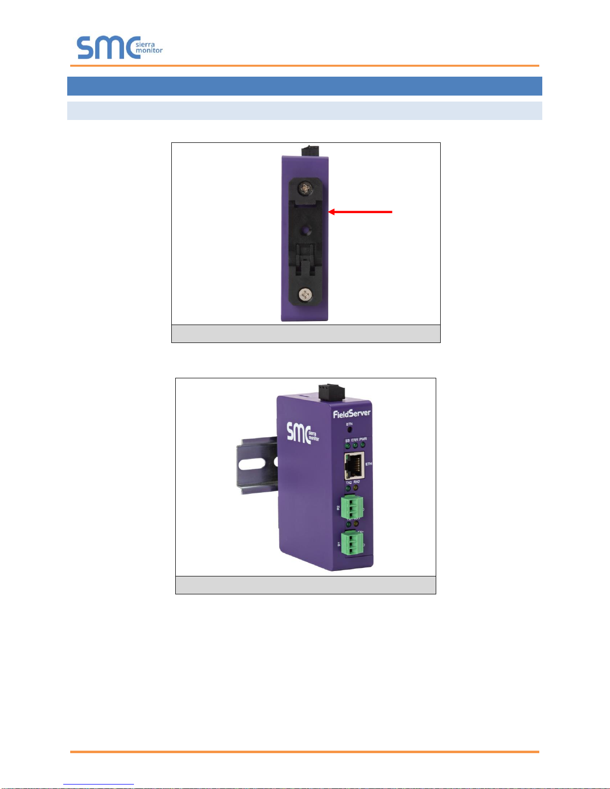
4.1 Mounting
The EZ Gateway can be mounted using the DIN rail mounting bracket on the back of the unit.
NOTE: For dimension details see Appendix B.3.
Figure 1: DIN Rail Bracket
Figure 2: DIN Rail Mounted
Din Rail
Bracket
Page 8
EZ Gateway Modbus to BACnet Start-up Guide
Page 8 of 49
4.2 DIP Switch Settings
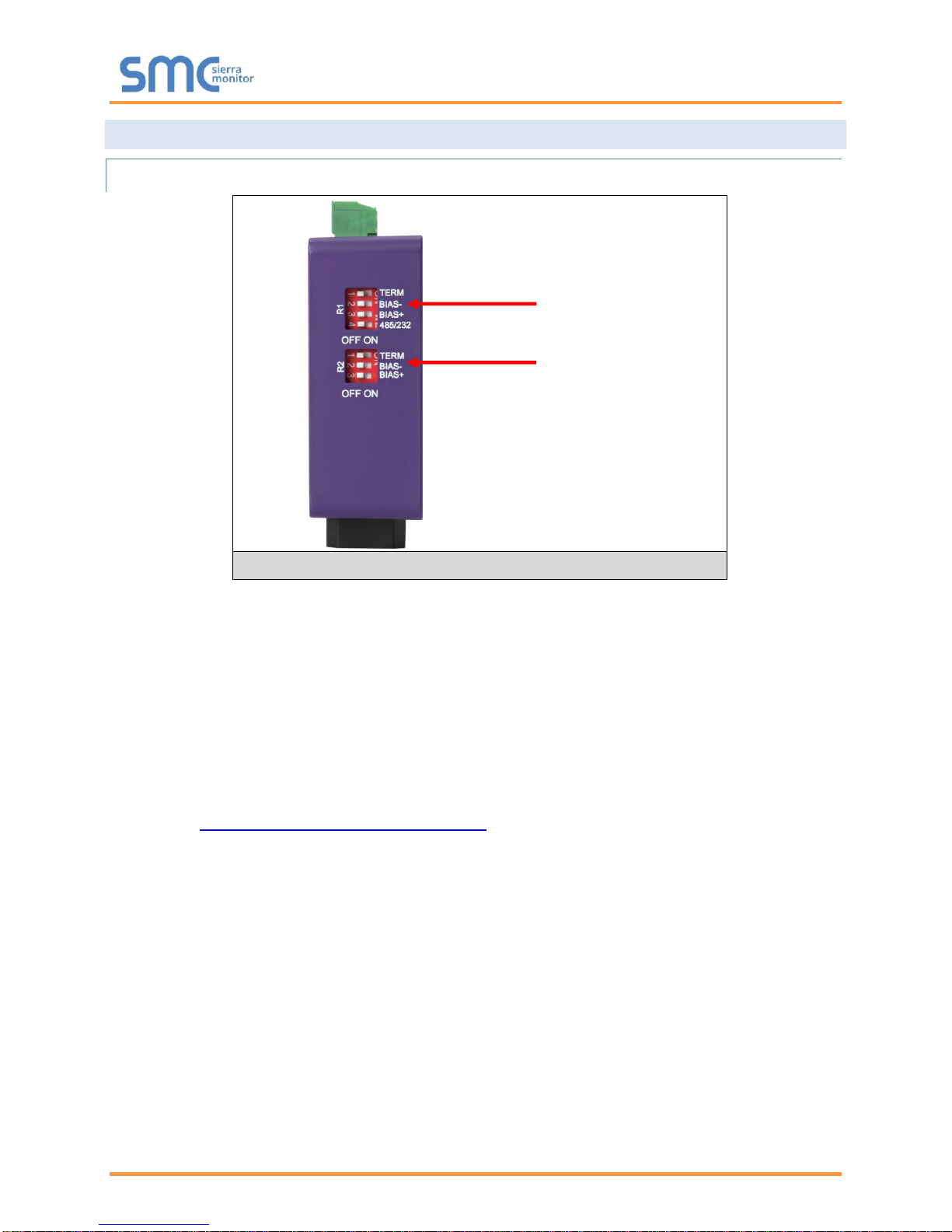
4.2.1 Bias Resistors
To enable Bias Resistors, move both the BIAS- and BIAS+ dip switches to the right in the
orientation shown in Figure 3.
The EZ Gateway bias resistors are used to keep the RS-485 bus to a known state, when there is no
transmission on the line (bus is idling), to help prevent false bits of data from being detected. The bias
resistors typically pull one line high and the other low - far away from the decision point of the logic.
The bias resistor is 510 ohms which is in line with the BACnet spec. It should only be enabled at one
point on the bus (for example, on the field port were there are very weak bias resistors of 100k). Since
there are no jumpers, many EZ Gateways can be put on the network without running into the bias resistor
limit which is < 500 ohms.
NOTE: See www.ni.com/support/serial/resinfo.htm for additional pictures and notes.
NOTE: The R1 and R2 DIP Switches apply settings to the respective serial port.
NOTE: If the gateway is already powered on, DIP switch settings will not take effect unless the
unit is power cycled.
R1 Bias Resistor DIP
Switches (2 and 3)
Figure 3: Bias Resistor DIP Switches
R2 Bias Resistor DIP
Switches (2 and 3)
Page 9
EZ Gateway Modbus to BACnet Start-up Guide
Page 9 of 49
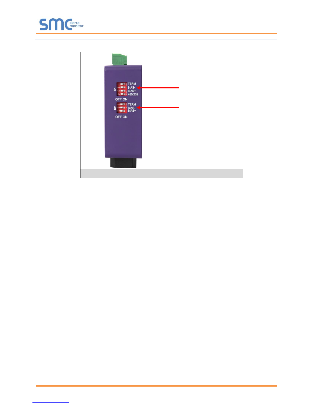
4.2.2 Termination Resistor
If the EZ Gateway is the last device on the serial trunk, then the End-Of-Line Termination Switch needs to
be enabled. To enable the Termination Resistor, move the TERM dip switch to the right in the
orientation shown in Figure 4.
Termination resistor is also used to reduce noise. It pulls the two lines of an idle bus together. However,
the resistor would override the effect of any bias resistors if connected.
NOTE: The R1 and R2 DIP Switches apply settings to the respective serial port.
NOTE: If the gateway is already powered on, DIP switch settings will not take effect unless the
unit is power cycled.
Figure 4: Termination Resistor DIP Switch
R1 Termination
Resistor DIP Switch (1)
R2 Termination
Resistor DIP Switch (1)
Page 10
EZ Gateway Modbus to BACnet Start-up Guide
Page 10 of 49
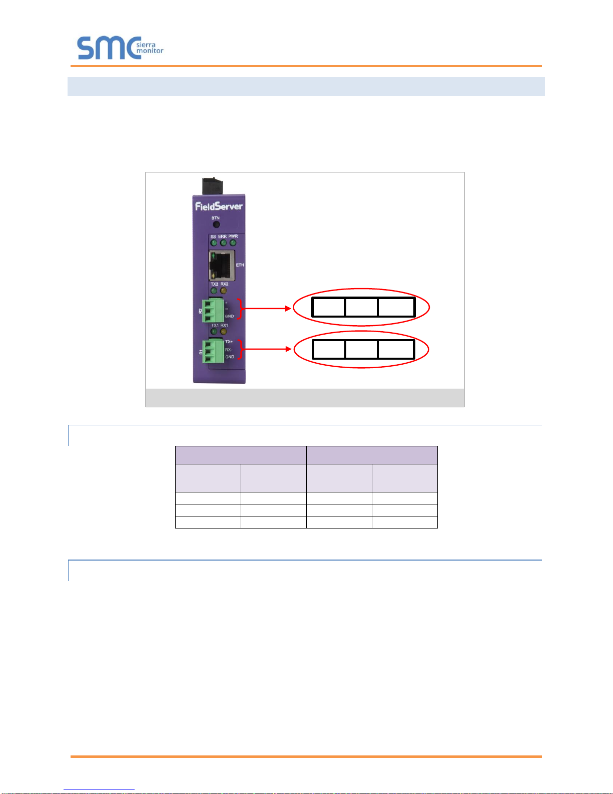
4.3 Connecting the R1 Port
For the R1 Port only: Switch between RS-485 and RS-232 by moving the number 4 DIP Switch left for
RS-485 and right for RS-232 (Figure 4).
The R2 Port is RS-485.
Connect to the 3-pin connector(s) as shown below.
4.3.1 Wiring
RS-485
RS-232
BMS RS-485
Wiring
Gateway Pin
Assignment
BMS RS-232
Wiring
Gateway Pin
Assignment
RS-485 +
TX +
RS-232 -
TX +
RS-485 -
RX -
RS-232 +
RX -
GND
GND
GND
GND
NOTE: Use standard grounding principles for GND.
4.3.2 Supported RS-485 Baud Rates by Protocol
The supported baud rates for either port is based on the protocol of the connected devices.
The following baud rates are supported for Modbus RTU:
2400, 4800, 9600, 19200, 38400, 57600, 76800, 115200
The following baud rates are supported for BACnet MS/TP:
9600, 19200, 38400, 76800
TX+ RX- GND
+ - GND
Figure 5: R1 & R2 Connection Ports
Page 11
EZ Gateway Modbus to BACnet Start-up Guide
Page 11 of 49
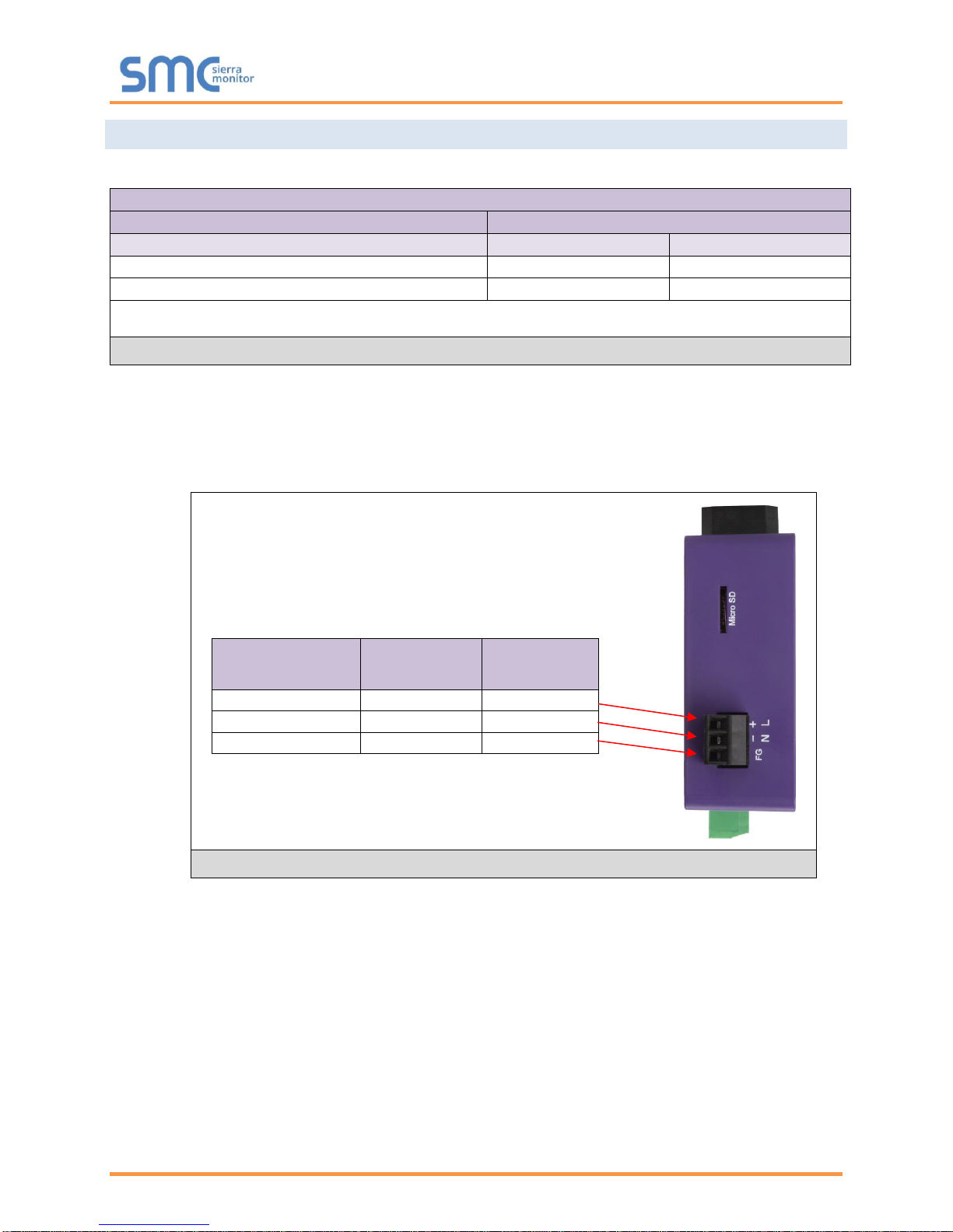
4.4 Power Up the Device
Check power requirements in the table below:
Power Requirement for External Gateway
Current Draw Type
EZ Gateway Family
12VDC
24V DC/AC
FS-EZ3-MOD-BAC (Typical)
250mA
125mA
FS-EZ4-MOD-BAC (Typical)
250mA
125mA
NOTE: These values are ‘nominal’ and a safety margin should be added to the power supply of
the host system. A safety margin of 25% is recommended.
Figure 6: Required Current Draw for the Gateway
Apply power to the EZ Gateway as shown below in Figure 7. Ensure that the power supply used
complies with the specifications provided in Appendix B.1.
• The gateway accepts 12-24VDC or 24VAC on pins 4 and 5.
• Frame GND should be connected.
Power to
Gateway
Gateway
Pin #
Pin
Assignment
Power In (+)
Pin 4
V +
Power In (-)
Pin 5
V -
Frame Ground
Pin 6
FRAME GND
Figure 7: Power Connections
Page 12
EZ Gateway Modbus to BACnet Start-up Guide
Page 12 of 49
5 CONNECT THE PC TO THE EZ GATEWAY
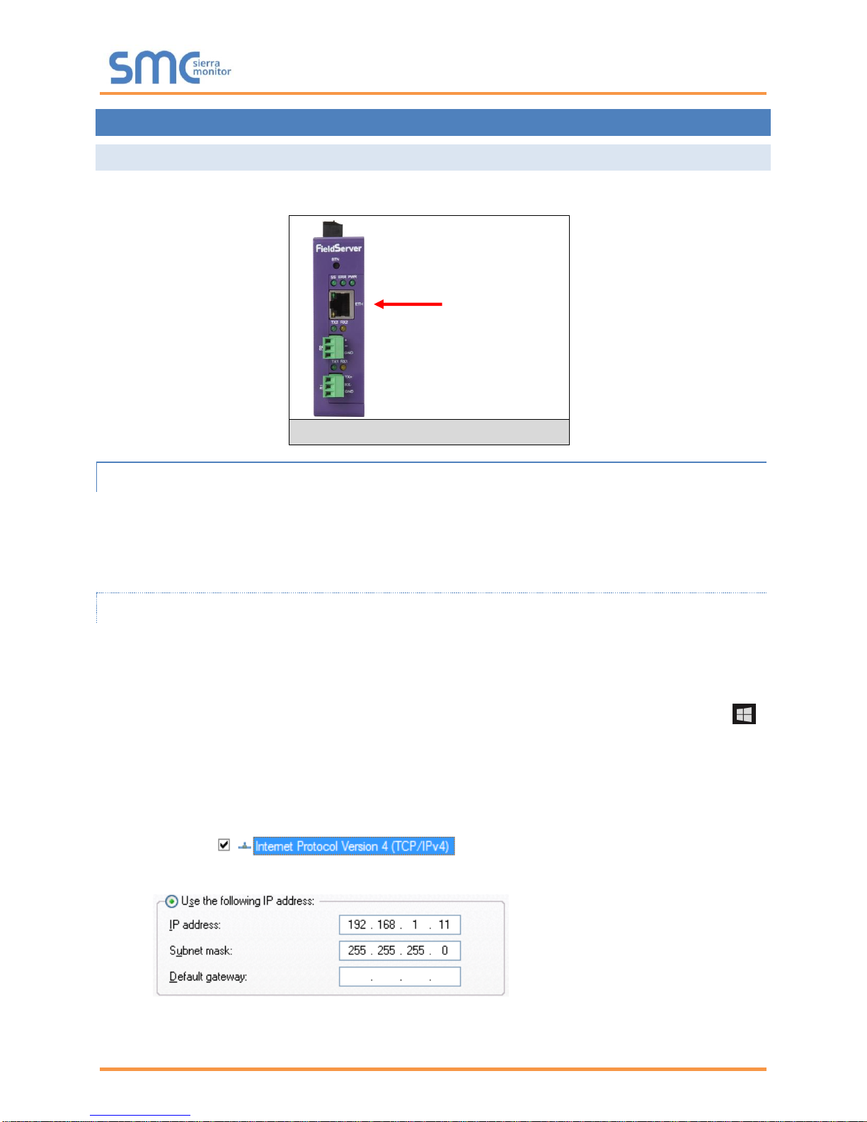
5.1 Connecting to the Gateway via Ethernet
First, connect a Cat-5 Ethernet cable (straight through or cross-over) between the local PC and the EZ
Gateway.
5.1.1 Enable Access Through the Local Browser
There are two methods to enable access to the EZ Gateway in the local browser, either by
changing the subnet of the connected PC (Section 5.1.1.1) or using the FieldServer Toolbox to
change the IP Address of the EZ Gateway (Section 5.1.1.2).
NOTE: Only perform one method or the other.
5.1.1.1 Changing the Subnet of the Connected PC
The default IP Address for the EZ Gateway is 192.168.2.101, Subnet Mask is 255.255.255.0. If the PC
and EZ Gateway are on different IP networks, assign a static IP Address to the PC on the 192.168.1.xxx
network.
For Windows 10:
• Find the search field in the local computer’s taskbar (usually to the right of the windows icon )
and type in “Control Panel”.
• Click “Control Panel”, click “Network and Internet” and then click “Network and Sharing Center”.
• Click “Change adapter settings” on the left side of the window.
• Right-click on “Local Area Connection” and select “Properties” from the dropdown menu.
• Highlight and then click the Properties button.
• Select and enter a static IP Address on the same subnet. For example:
• Click the Okay button to close the Internet Protocol window and the Close button to close the
Ethernet Properties window.
Ethernet Port
Figure 8: Ethernet Port Location
Page 13
EZ Gateway Modbus to BACnet Start-up Guide
Page 13 of 49
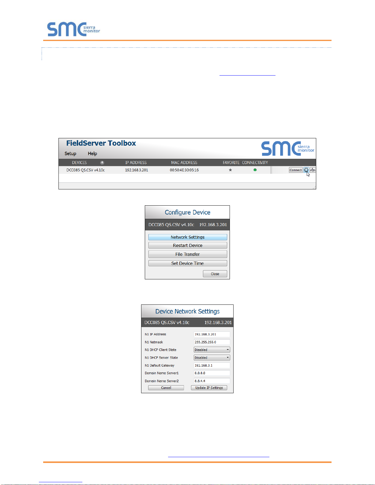
5.1.1.2 Changing the IP Address of the EZ Gateway with FieldServer Toolbox
• Ensure that FieldServer Toolbox is loaded onto the local PC. Otherwise, download the
FieldServer-Toolbox.zip via the Sierra Monitor website’s Software Downloads.
• Extract the executable file and complete the installation.
• Double click on the FS Toolbox Utility and click Discover Now on the splash page.
• Find the desired gateway and click the Configure Device button (gear icon) to the right of the
gateway information.
NOTE: If connectivity status is green, then the IP Address doesn’t need to be changed (the EZ
Gateway is already on the same subnet). Skip the rest of the section and go to Section 5.2.
• Select Network Settings in the Configure Device window.
• Modify the IP Address (N1 IP Address field) of the gateway Ethernet port.
o Change additional fields as needed
NOTE: If the gateway is connected to a router, the Default Gateway field of the gateway should be
set to the IP Address of the connected router.
NOTE: Do not change the DHCP Server State (N1 DHCP Server State field).
NOTE: If DNS settings are unknown, set DNS1 to “8.8.8.8” and DNS2 to “8.8.4.4”.
• Click Update IP Settings, then click the “Change and restart” button to reboot the Gateway and
activate the new IP Address. See the FieldServer Toolbox and GUI Manual for more information.
Page 14
EZ Gateway Modbus to BACnet Start-up Guide
Page 14 of 49
5.2 Using Web Configurator GUI
• Open a web browser and connect to the EZ Gateway’s default IP Address. The default IP
Address of the FieldServer is 192.168.2.101, Subnet Mask is 255.255.255.0.
• If the PC and the EZ Gateway are on different IP networks, assign a static IP Address to the PC
on the 192.168.2.X network.
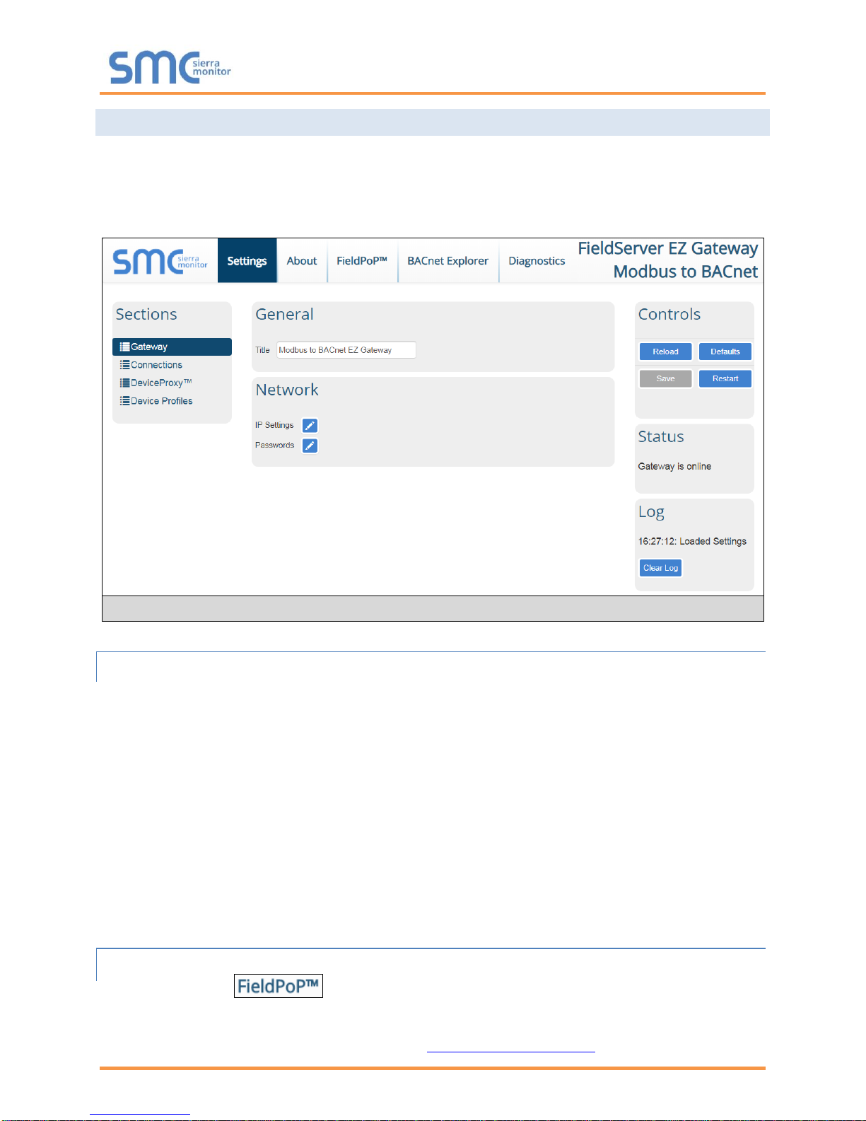
5.2.1 Controls, Status and Log Functions
Along the right side of every Web Configurator GUI page is a column of buttons and event generated
messages.
• Controls Panel – Contains the following four buttons:
o Reload – Resets all settings to the last saved configuration
o Defaults – Resets all settings to the default configuration
o Save – Records all settings
o Restart – Reboots the Gateway
• Status Information – Shows Gateway messages such as whether the Gateway is online,
element validation status, unsaved settings, etc.
• Log Messages – Lists last five events and when they were performed.
5.2.2 Accessing SMC Cloud
The FieldPoP™ tab (see Figure 9) allows users to connect to the SMC Cloud, Sierra
Monitor’s device cloud solution for IIoT. The SMC Cloud enables secure remote connection to field
devices through a FieldServer and its local applications for configuration, management, maintenance. For
more information about the SMC Cloud, refer to the SMC Cloud Start-up Guide.
Figure 9: EZ Gateway Landing Page
Page 15
EZ Gateway Modbus to BACnet Start-up Guide
Page 15 of 49
6 CONFIGURING THE EZ GATEWAY
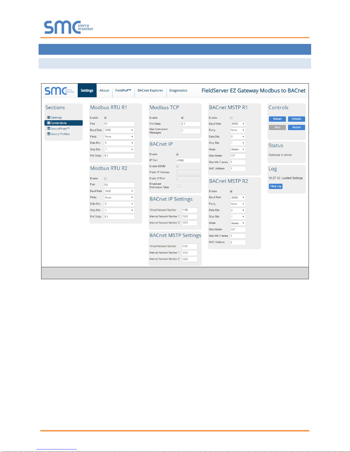
6.1 Setting up the Connections
• Open the Connections page to configure the connection ports and parameters.
• Click the Save button in the Controls section once completed.
• Then click Restart to implement the new settings.
Figure 10: Connections Page
Page 16

EZ Gateway Modbus to BACnet Start-up Guide
Page 16 of 49
6.2 Creating Device EZ Profiles
• Open the Device Profiles page to create a new profile.
• Create a data map using one of two methods:
o Create Modbus to BACnet mapping using the Web Interface (Section 6.2.1)
o Create Modbus to BACnet mapping using Excel Profile Generator (Section 6.2.2)
• After saving the data map, complete the profile setup by updating State Tables and Notification
Classes as needed. (Section 6.2.3)
Figure 11: Device Profiles Page
Page 17

EZ Gateway Modbus to BACnet Start-up Guide
Page 17 of 49
6.2.1 Using the Device Web Interface to Map BACnet Objects
NOTE: The Add button creates another blank profile that must be mapped using the Web
Interface.
• Click on the Edit button (pencil icon) next to the name of the profile to map.
• Enter the Modbus and BACnet parameters.
NOTE: See for Appendix B.4 additional information on Address Type.
• Click on the Data Map tab and add the first Modbus address range.
NOTE: Check the Signed Value checkbox (right of the data map entry) if signed values are
needed.
Figure 13: Data Map Window
Figure 12: Edit Profile Window
Page 18

EZ Gateway Modbus to BACnet Start-up Guide
Page 18 of 49
• Click on the blue plus sign icon on the left side of the Address to map the BACnet Addresses to
the Modbus Registers.
NOTE: The Advanced button (eye icon) allows additional settings, including: Intrinsic Reporting,
Bit Extraction, scaling and more.
• Repeat for all of the Modbus registers.
• Once all mappings are defined, click the “Save” button in the bottom left corner of the window to
record the Profile.
Figure 15: Save Button
Figure 14: Mapping BACnet Addresses to Modbus Registers
Page 19

EZ Gateway Modbus to BACnet Start-up Guide
Page 19 of 49
6.2.2 Using Excel Profile Generator to Map BACnet Objects
• From the Device Profiles page (Figure 11), click on the “Download Excel Profile Generator” link
to download the Excel spreadsheet used to create the profile to the default download folder on
the local PC.
• Open the downloaded Excel spreadsheet and ensure that the content is not disabled by security
settings (yellow security warning bar across the top of the spread sheet).
NOTE: If the security warning is present simply click the Enable Content button found at the end
of the warning.
• Click the Data Map tab (near the bottom of the Excel spreadsheet).
• Edit or copy in Modbus registers as needed.
• Once all the point mappings are complete, switch back to the Generate Profile tab.
• Click the Generate Profile button to create a new Excel .csv file titled “My Modbus Profile”.
• Go back to the EZ Gateway Device Profiles page (Figure 11) and click the Import button.
• Select the Excel .csv file and click the checkbox to load the mapping.
• Once all mappings are loaded, click Save in the Controls section.
Figure 16: Profile Generator Excel Spreadsheet
Page 20

EZ Gateway Modbus to BACnet Start-up Guide
Page 20 of 49
6.2.3 Completing Device Profile Setup
• Click on the Edit button (pencil icon) next to the name of the profile to complete setup.
• If a data map was loaded from a file created from the “Excel Profile Generator”, go to the Device
Settings tab to enter the Modbus and BACnet parameters.
NOTE: See for Appendix B.4 additional information on Address Type.
• If using a BACnet State Table, click on the “State Table” tab to define the table and its variables.
Figure 18: State Table Window
Figure 17: Device Settings Window
Page 21

EZ Gateway Modbus to BACnet Start-up Guide
Page 21 of 49
• To define a Notification Class, click the “Notification Class” tab and define the parameters as
needed.
• Once all settings are defined, click the “Save” button in the bottom left corner of the window to
record the Profile.
6.2.4 Export Profile for Backup or Future Use
• Back on the Device Profiles page, the profile can be exported for backup or future use by hitting
the Export Profile button (hard drive icon).
• The profile downloads to the local computer in the format: <Profile Name>.profile
Figure 21: Export Profile
Figure 19: Notification Class Window
Figure 20: Save Button
Page 22

EZ Gateway Modbus to BACnet Start-up Guide
Page 22 of 49
6.3 Importing a Device Profile
• Profiles on the local computer can be imported to the EZ Gateway by going to the Device Profiles
page and clicking the Import button.
NOTE: All profiles will need to be created or imported to the EZ Gateway before proceeding.
NOTE: There are two types of files that can be imported. The Excel spreadsheet generated files
(Section 6.2.2) or an exported profile (Section 6.2.4). Files generated from the downloaded
“Excel Profile Generator” only include Data Map information and must be completed by
going through the steps found in Section 6.2.3 after being loaded. However, exported
profiles include complete profile information and can be used immediately after load up.
Figure 22: Importing a Device Profile
Page 23

EZ Gateway Modbus to BACnet Start-up Guide
Page 23 of 49
6.4 Mapping BACnet Output with Device EZ Profiles
• Open the DeviceProxy™ page.
• Choose the Device Profile to load from the drop down menu.
NOTE: If required, click the Advanced Settings button (eye icon) to enter the Device Description
and Device Location.
• Choose the appropriate connection and Node ID/BACnet Device Instance for both the incoming
Modbus device and the mapped BACnet output.
• Click Add to include additional device profiles in the Configuration.
• Repeat for all Modbus devices intended to connect to the EZ Gateway.
• Click the Save button in the Controls section once all device EZ Profiles are added and then click
the Restart button to reset the system.
Figure 24: Controls Section
Figure 23: Choose Profile to Load
Page 24

EZ Gateway Modbus to BACnet Start-up Guide
Page 24 of 49
6.5 Test and Commission the EZ Gateway
• Connect the EZ Gateway to the third party device(s), and test the application.
• Click on the Diagnostic button to view to get to the FS-GUI.
• From the landing page of the FS-GUI click on View in the navigation tree, then Connections to
see the number of messages on each protocol.
NOTE: For troubleshooting assistance refer to Appendix A, or any of the troubleshooting
appendices in the related driver supplements and configuration manual. Sierra Monitor
also offers a technical support on the Sierra Monitor website, which contains a significant
number of resources and documentation that may be of assistance.
NOTE: The FieldPoP™ button (see Figure 25) allows users to connect to the SMC
Cloud, Sierra Monitor’s device cloud solution for IIoT. The SMC Cloud enables secure
remote connection to field devices through a FieldServer and its local applications for
configuration, management, maintenance. For more information about the SMC Cloud,
refer to the SMC Cloud Start-up Guide.
Figure 25: FS-GUI Connections Screen
Page 25

EZ Gateway Modbus to BACnet Start-up Guide
Page 25 of 49
7 USING THE EMBEDDED BACNET EXPLORER
The embedded BACnet Explorer allows installers of the product to validate that their equipment is
working on BACnet without having to ask the BMS integrator to test the unit.
• To access the embedded BACnet Explorer, click the BACnet Explorer tab at the top of the
screen.
• Then login to the BACnet Explorer page using the supplied username and password.
NOTE: The default user name is “admin” and the default password is “admin”.
NOTE: For BACnet/IP, click on the Connections page to ensure the EZ Gateway is on the
BACnet/IP network subnet or to configure BBMD.
Figure 26: BACnet Explorer Tab
Figure 27: BACnet Explorer Login Page
Page 26

EZ Gateway Modbus to BACnet Start-up Guide
Page 26 of 49
7.1 Discover Device List
• From the BACnet Explorer landing page, click on the BACnet Explorer button on the left side of
the screen to go to the BACnet Explorer page.
• To discover the devices connected to the same subnet as the BACnet Explorer, click the
Discover button (binocular icon).
• This will open the Discover window, click the checkboxes next to the desired search settings and
click Discover to start the search.
NOTE: The “Discover All Devices” or “Discover All Networks” checkboxes must be unchecked to
search for a specific device range or network.
Figure 28: BACnet Explorer Page
Figure 29: Discover Window
Page 27

EZ Gateway Modbus to BACnet Start-up Guide
Page 27 of 49
NOTE: Allow the devices to populate before interacting with the device list for optimal
performance. Any discovery or explore process will cause a green message to appear in
the upper right corner of the browser to confirm that the action is complete.
7.2 View Device Details and Explore Points/Parameters
• To view the device details, click the blue plus sign ( ) next to the desired device in the list.
o This will show only some of the device properties for the selected aspect of a device
Figure 30: Device List
Figure 31: Device Sub-items
Page 28

EZ Gateway Modbus to BACnet Start-up Guide
Page 28 of 49
• To view the full details of a device, highlighting the device directly (in Figure 32 “1991
WeatherLink_1”) and click the Explore button ( ) that appears to the right of the highlighted
device as a magnifying glass icon or double-click the highlighted device.
o Now additional device details are viewable; however, the device can be explored even further
• Click on one of the device details.
Figure 33: Simplified Device Details
Figure 32: Full Device Sub-items
Page 29

EZ Gateway Modbus to BACnet Start-up Guide
Page 29 of 49
• Then click on the Explore button or double-click the device object.
A full list of the device details will appear on the right side window. If changes are expected since the last
explore, simply press the Refresh button ( ) that appears to right of individual properties to refresh the
value.
NOTE: The Explorer Search Bar will find devices based on their Device ID.
NOTE: The Explorer Discovery Tree has 3 levels that correspond to the following.
• Network number
o Device
▪ Device object
Figure 34: Additional Device Details
Page 30

EZ Gateway Modbus to BACnet Start-up Guide
Page 30 of 49
7.2.1 Edit the Present Value Field
The only recommended field to edit via BACnet Explorer is the device’s present value field.
NOTE: Other BACnet properties are editable (such as object name, object description, etc.);
however, this is not recommended because the BACnet Explorer is a discovery tool not a
Building Management System (BMS).
• To edit the present value, select it in the property listings.
• Then click the Write button ( ) on the right of the property to bring up the Write Property
window.
Figure 35: Highlighted Present Value
Figure 36: Write Property Window
Page 31

EZ Gateway Modbus to BACnet Start-up Guide
Page 31 of 49
• Enter the appropriate change and click the Write button.
The window will close. When the BACnet Explorer page appears, the present value will be
changed as specified.
Figure 37: Updated Present Value
Page 32

EZ Gateway Modbus to BACnet Start-up Guide
Page 32 of 49
8 SMC CLOUD USER SETUP, REGISTRATION AND LOGIN
8.1 User Setup
Request an invitation to SMC Cloud from the manufacturer’s support team and follow the instructions
below to set up login details:
• The “Welcome to SMC Cloud” email will appear as shown below.
NOTE: If no SMC Cloud email was received, check the spam/junk folder for an email from
notification@fieldpop.io. Contact the manufacturer’s support team if the email cannot be
found.
Figure 38: Welcome to SMC Cloud Email
Page 33

EZ Gateway Modbus to BACnet Start-up Guide
Page 33 of 49
• Click the “Complete Registration” button and fill in user details accordingly.
• Fill in the name, phone number, password fields and check the checkbox to agree to the privacy
policy and terms of service.
• Click “Save” to save the user details.
• Click “OK” on when the Success message appears.
• Record the email account used and password for future use.
Figure 39: Setting User Details
Page 34

EZ Gateway Modbus to BACnet Start-up Guide
Page 34 of 49
8.2 Registration Process
Once SMC Cloud user credentials have been generated, the EZ Gateway can be registered onto the
SMC Cloud server.
• Click on the FieldPoP™ tab across the top of the screen.
• The following informational splash page will appear, click Close to view the registration page.
Figure 41: Registration Information Page
Figure 40: Web App Landing Page – FieldPoP Tab
Page 35

EZ Gateway Modbus to BACnet Start-up Guide
Page 35 of 49
• If a warning message appears instead of the splash page, follow the suggestion that appears on
screen.
• If the EZ Gateway cannot reach the SMC Cloud server, the following message will appear.
o Follow the directions presented in the warning message and check that the DNS settings are
set up with the following Domain Name Server (DNS) settings:
DNS1=8.8.8.8
DNS2=8.8.4.4
o Ensure that the EZ Gateway is properly connected to the Internet
NOTE: If changes to the network settings are done, remember to click “Update IP Settings” and
then power cycle the EZ Gateway.
Figure 42: SMC Cloud Connection Problems Message
Page 36

EZ Gateway Modbus to BACnet Start-up Guide
Page 36 of 49
• On the registration page, fill in user credentials and all other device information fields for
registration of each individual gateway in the field.
• To input the device location, do one of the following:
o Enter the address in the address field
o Click the “Get Current Location” button to auto-populate
NOTE: This button will only work if location services have been enabled on the local browser. If
using the Chrome browser and connected via LAN, this method will not work.
o Drop a location directly on the Google map
o Enter the latitude and longitude manually
• Click Register Device.
Figure 43: SMC Cloud Registration Page
Page 37

EZ Gateway Modbus to BACnet Start-up Guide
Page 37 of 49
• Once the device has successfully been registered, the following screen will appear listing the
device details and additional information auto-populated by the EZ Gateway.
Figure 44: Device Registered for SMC Cloud
Page 38

EZ Gateway Modbus to BACnet Start-up Guide
Page 38 of 49
8.3 Login to SMC Cloud
After the EZ Gateway is registered, go to www.smccloud.net and type in the appropriate login information
as per registration credentials.
NOTE: If the login password is lost, see the SMC Cloud Start-up Guide for recovery instructions.
On first login, the Privacy Policy window will appear. Read the Terms of Service, click the checkbox to
accept the terms and then click the Continue button to access SMC Cloud.
Figure 45: SMC Cloud Login Page
Figure 46: SMC Cloud Privacy Policy
Page 39

EZ Gateway Modbus to BACnet Start-up Guide
Page 39 of 49
NOTE: For additional SMC Cloud instructions see the SMC Cloud Start-up Guide.
Figure 47: SMC Cloud Landing Page
Page 40

EZ Gateway Modbus to BACnet Start-up Guide
Page 40 of 49
Appendix A Troubleshooting
Appendix A.1. Communicating with the EZ Gateway Over the Network
• Confirm that the network cabling is correct.
• Confirm that the computer network card is operational and correctly configured.
• Confirm that there is an Ethernet adapter installed in the PC’s Device Manager List, and that it is
configured to run the TCP/IP protocol.
• Check that the IP netmask of the PC matches the EZ Gateway. The Default IP Address of the EZ
Gateway is 192.168.2.X, Subnet Mask is 255.255.255.0.
o Go to Start|Run
o Type in “ipconfig”
o The account settings should be displayed
o Ensure that the IP Address is 102.168.2.X and the netmask 255.255.255.0
• Ensure that the PC and EZ Gateway are on the same IP Network, or assign a Static IP Address to
the PC on the 192.168.2.X network.
Appendix A.2. Notes Regarding Subnets and Subnet Masks
RFC standards allocate the IP Address range of 192.0.0.0 through to 223.255.255.255 to be used in
Class-C subnetting (subnets listed as 255.255.255.xxx, where xxx can vary based on filtering required).
Consequently, the IP stack for this product will not allow any IP Addresses in this range to be allocated a
subnet that does not fall within the Class C range.
Page 41

EZ Gateway Modbus to BACnet Start-up Guide
Page 41 of 49
Appendix A.3. Before Contacting Technical Support Take a Diagnostic Capture
When there is a problem on-site that cannot easily be resolved, perform a diagnostic capture before
contacting support so that support can quickly solve the problem. There are two methods for taking
diagnostic captures:
• FieldServer Toolbox:
This method requires installation of the FS Toolbox program. A FS Toolbox diagnostic capture
takes a snapshot of the loaded configuration files and a log of all the communications on the
serial ports over a specified period of time. If the problem occurs over an Ethernet connection,
then take a Wire Shark capture.
• Gateway’s FS-GUI Page:
This method doesn’t require downloading software. The diagnostic capture utilities are embedded
in the FS-GUI web interface. Starting a diagnostic capture takes a snapshot of the loaded
configuration files and a log of all the communications over a specified period of time. This works
for both serial and Ethernet connections.
NOTE: The information in the zipped files contains everything support needs to quickly resolve
problems that occur on-site.
Appendix A.3.1. Using the FieldServer Toolbox
Once the Diagnostic Capture is complete, email it to technical support. The Diagnostic Capture
will accelerate diagnosis of the problem.
NOTE: While all necessary documentation is shipped with the FieldServer on the USB flash drive,
these documents are constantly being updated. Newer versions may be available on the
Sierra Monitor website.
• Ensure that FieldServer Toolbox is loaded onto the local PC. Otherwise, download the
FieldServer-Toolbox.zip via the Sierra Monitor Software Downloads.
• Extract the executable file and complete the installation.
• Connect a standard Cat-5 Ethernet cable between the PC and FieldServer.
• Double click on the FS Toolbox Utility.
Figure 48: Ethernet Port Location
Ethernet Port
Page 42

EZ Gateway Modbus to BACnet Start-up Guide
Page 42 of 49
• Step 1: Take a Log
o Click on the diagnose icon of the desired device
o Ensure “Full Diagnostic" is selected (this is the default)
NOTE: If desired, the default capture period can be changed.
Page 43

EZ Gateway Modbus to BACnet Start-up Guide
Page 43 of 49
o Click on “Start Diagnostic”
o Wait for Capture period to finish, then the Diagnostic Test Complete window will appear
• Step 2: Send Log
o Once the Diagnostic test is complete, a .zip file will be saved on the PC
o Choose “Open” to launch explorer and have it point directly at the correct folder
o Send the Diagnostic zip file to support@sierramonitor.com
Page 44

EZ Gateway Modbus to BACnet Start-up Guide
Page 44 of 49
Appendix A.3.2. Using FS-GUI
Diagnostic Capture with FS-GUI is only available on FieldServers with a bios updated/released on
November 2017 or later. Completing a Diagnostic Capture through the FieldServer allows network
connections (such as Ethernet and Wi-Fi) to be captured.
Once the Diagnostic Capture is complete, email it to technical support. The Diagnostic Capture
will accelerate diagnosis of the problem.
• Open the FieldServer FS-GUI page.
• Click on Diagnostics in the Navigation panel.
• Go to Full Diagnostic and select the capture period.
• Click the Start button under the Full Diagnostic heading to start the capture.
o When the capture period is finished, a Download button will appear next to the Start button
• Click Download for the capture to be downloaded to the local PC.
• Send the diagnostic zip file to support@sierramonitor.com.
Page 45

EZ Gateway Modbus to BACnet Start-up Guide
Page 45 of 49
Appendix A.4. LED Functions
Tag
Description
SS
The SS LED will light if the unit is not getting a response from one or more of the configured devices.
ERR
The SYS ERR LED will go on solid indicating there is a system error. If this occurs, immediately report
the related “system error” shown in the error screen of the FS-GUI interface to support for evaluation.
PWR
This is the power light and should always be steady green when the unit is powered.
TX
The TX LED will flash when a message is received on the serial port on the 3-pin connector.
If the serial port is not used, this LED is non-operational. TX1 applies to the R1 connection while
TX2 applies to the R2 connection.
RX
The RX LED will flash when a message is sent on the serial port on the 3-pin connector.
If the serial port is not used, this LED is non-operational. RX1 applies to the R1 connection while
RX2 applies to the R2 connection.
Figure 49: Diagnostic LEDs
FS-EZX-MOD-BAC
Diagnostic LEDs
Page 46

EZ Gateway Modbus to BACnet Start-up Guide
Page 46 of 49
Appendix B Reference
Appendix B.1. Specifications
FS-EZ3-MOD-BAC & FS-EZ4-MOD-BAC 2
Electrical Connections
One 3-pin Phoenix connector with: RS-485/RS-232 (Tx+ / Rx- / gnd)
One 3-pin Phoenix connector with: RS-485 (Tx+ / Rx- / gnd)
One 3-pin Phoenix connector with: Power port (+ / - / Frame-gnd)
One Ethernet 10/100 BaseT port
Power Requirements
Input Voltage: 12-24VDC or 24VAC Current draw: 24VAC 125mA
Max Power: 3 Watts 12-24VDC 250mA @12VDC
Approvals
CE and FCC Class B & C Part 15, UL 60950, WEEE compliant,
IC Canada, RoHS compliant
Power Requirements
12-24VDC or 24VAC
Physical Dimensions
4 x 1.1 x 2.7 in (10.16 x 2.8 x 6.8 cm)
Weight
0.4 lbs (0.2 Kg)
Operating Temperature
-20°C to 70°C (-4°F to158°F)
Humidity
10-95% RH non-condensing
Figure 50: Specifications
“This device complies with part 15 of the FCC Rules. Operation is subject to the following two conditions:
• This device may not cause harmful interference
• This device must accept any interference received, including interference that may cause
undesired operation.
NOTE: This equipment has been tested and found to comply with the limits for a Class A digital device,
pursuant to part 15 of the FCC Rules. These limits are designed to provide reasonable protection
against harmful interference when the equipment is operated in a commercial environment. This
equipment generates, uses, and can radiate radio frequency energy and, if not installed and used in
accordance with the instruction manual, may cause harmful interference to radio communications.
Operation of this equipment in a residential area is likely to cause harmful interference in which case
the user will be required to correct the interference at his expense.
Modifications not expressly approved by Sierra Monitor could void the user's authority to operate the
equipment under FCC rules”.
2
Specifications subject to change without notice.
Page 47

EZ Gateway Modbus to BACnet Start-up Guide
Page 47 of 49
Appendix B.2. Compliance with UL Regulations
For UL compliance, the following instructions must be met when operating the EZ Gateway.
• The units shall be powered by listed LPS or Class 2 power supply suited to the expected
operating temperature range.
• The interconnecting power connector and power cable shall:
o Comply with local electrical code
o Be suited to the expected operating temperature range
o Meet the current and voltage rating for the EZ Gateway
• Furthermore, the interconnecting power cable shall:
o Be of length not exceeding 3.05m (118.3”)
o Be constructed of materials rated VW-1, FT-1 or better
• If the unit is to be installed in an operating environment with a temperature above 65 °C, it should
be installed in a Restricted Access Area requiring a key or a special tool to gain access.
• This device must not be connected to a LAN segment with outdoor wiring.
Appendix B.3. Dimension Drawing FS-EZX-MOD-BAC
Figure 51: EZ Gateway Dimension Drawing
R1 Serial Port
Power Port
R2 Serial Port
Page 48

EZ Gateway Modbus to BACnet Start-up Guide
Page 48 of 49
Appendix B.4. Address Types and Data Types
If the node parameter Address_Type is set as ADU or PDU, then Data_Type must be specified as
follows.
For Address_Type ADU:
Address range
Data_Type
Function Code (Write)
Function Code (Read)
1 - 65536
Coil
15
1
1 – 65536
Discrete_Input
n/a.
2
1 – 65536
Input_Register
n/a.
4
1 - 65536
Holding_Register
16
3
For Address_Type PDU:
Address range
Data_Type
Function Code (Write)
Function Code (Read)
0 - 65535
FC01
15
1
0 – 65535
FC02
n/a.
2
0 – 65535
FC04
n/a.
4
0 – 65535
FC03
16
3
For Address_Type Modicon_5digit:
When a Modbus address range is specified, a particular Data Type is implied. The defaults are shown
below.
Address range
Data_Type
Function Code (Write)
Function Code (Read)
00001 - 09999
Coil
5,15
1
10001 - 19999
Discrete_Input
n/a.
2
30001 - 39999
Input_Register
n/a.
4
40001 - 49999
Holding_Register
6,16
3
Page 49

EZ Gateway Modbus to BACnet Start-up Guide
Page 49 of 49
Appendix C Limited 2 Year Warranty
Sierra Monitor Corporation warrants its products to be free from defects in workmanship or material under
normal use and service for two years after date of shipment. Sierra Monitor Corporation will repair or
replace any equipment found to be defective during the warranty period. Final determination of the nature
and responsibility for defective or damaged equipment will be made by Sierra Monitor Corporation
personnel.
All warranties hereunder are contingent upon proper use in the application for which the product was
intended and do not cover products which have been modified or repaired without Sierra Monitor
Corporation’s approval or which have been subjected to accident, improper maintenance, installation or
application, or on which original identification marks have been removed or altered. This Limited Warranty
also will not apply to interconnecting cables or wires, consumables or to any damage resulting from
battery leakage.
In all cases Sierra Monitor Corporation’s responsibility and liability under this warranty shall be limited to
the cost of the equipment. The purchaser must obtain shipping instructions for the prepaid return of any
item under this warranty provision and compliance with such instruction shall be a condition of this
warranty.
Except for the express warranty stated above, Sierra Monitor Corporation disclaims all warranties with
regard to the products sold hereunder including all implied warranties of merchantability and fitness and
the express warranties stated herein are in lieu of all obligations or liabilities on the part of Sierra Monitor
Corporation for damages including, but not limited to, consequential damages arising out of/or in
connection with the use or performance of the product.
 Loading...