

Page 1
FFLLEEXXIIBBLLEE IINNTTEEGGRRAATTEEDD AASSSSEEMMBBLLIINNGG
SSYYSSTTEEMMSS
F
F
A
A
S
S--220000
Page 2

FAS-200
USER MANUAL
Page 3
Equipment for training in flexible integrated
assembling systems
F
F
F
l
l
l
e
e
e
x
x
x
i
i
i
b
b
b
l
l
l
e
e
e
A
A
A
s
s
s
s
s
s
e
e
e
m
m
m
b
b
b
l
l
l
y
y
y
S
S
S
y
y
y
s
s
s
t
t
t
e
e
e
m
m
m
F
F
F
A
A
A
S
S
S
-
-
-
2
2
2
0
0
0
0
0
0
Technical Description
Page 4

TEN REASONS FOR CHOOSING THE FAS200 SYSTEM
1. The FAS200 is manufactured entirely from industrial grade materials of maximum
strength and quality.
2. It complies with European safety directives in respect of both low voltage and
machine safety.
3. It may include pallet transfer integrate several modules allowing.
4. The process stations or layouts can work independently or integrated in the system in
cell mode.
5. The PLCs needed for system control are included, with mains supply
connection, and users may design their own electrical control gear based on other,
different, PLCs.
6. Each of the most of the modules incorporates a key-protected Fault Generation
System which makes it possible to work on diagnostic and repair capabilities, using the
“Switches” methodology .
7. The FAS200 cell has been designed for assembly of a turning mechanism with a total
of 24 variants.
8. The pallets and transfer incorporate a binary coding system using inductive
detectors, which allow the Control System to identify the position of each pallet at any
time.
Page 5

9. The system allow the development of skills such as: ANALYSIS, INSTALLATION/
ASSEMBLY/ IMPLEMENTATION, MAINTENANCE/ DIAGNOSIS/ FAULT REPAIR,
START-UP/ SET-UP, DESIGN/LAYOUT, PROGRAMMING, PREPARATION OF
DOCUMENTATION, DEFINITION OF PROCEDURES, MEASURING, ETC., integrating
different technologies including: Pneumatics/Electro-pneumatics, Hydraulics/Electrohydraulics, Electrical Actuators, Robotics/Manipulation, Industrial Communications, Control
Systems, Electric Automatisms, Safety Devices, Basic Mechanical Systems, Artificial
Vision Systems and so on.
10. It has been conceived and designed by a knowledgeable team with wide experience in
both the industrial and educational sectors.
Page 6

FLEXIBLE ASSEMBLY SYSTEM FAS200
User Manual for FAS200 - 4 -
INDEX
INDEX ......................................................................................................................................................... 4
1. CONFIGURATION .......................................................................................................................... 5
2. GENERAL OVERVIEW: ................................................................................................................ 9
FAS-230 LINEAR TRANSFER MODULE: TRANSPORT SYSTEM ........................................................ 13
TROUB-200 FAULT SIMULATION SYSTEM ................................................................................... 17
FAS-201 BASE FEEDING/VERIFICATION MODULE............................................................................ 18
FAS-202 BASE REJECTING/TRANSFERING MODULE............................................................................... 23
FAS-203 BEARING FEEDING/TRANSFERING MODULE .................................................................... 27
FAS-204 BEARING MEASURING/TRANSFERING MODULE ........................................................... 31
FAS-205 HYDRAULIC PRESSING MODULE ...................................................................................... 36
FAS-206 HYDRAULIC PRESS TRANSFERING MODULE ................................................................. 41
FAS-207 SHAFT CLASSIFICATION MODULE ................................................................................ 45
FAS-208 SHAFT REJECTING/TRANSFERING MODULE ............................................................................ 51
FAS-209 COVER CLASSIFICATION MODULE ................................................................................... 56
FAS-210 COVER REJECTING/TRANSFERING MODULE.................................................................. 63
FAS-211 SCREWS DISPENSING MODULE.......................................................................................... 67
FAS-212 SCREWS INSERTION MODULE ............................................................................................ 71
FAS-213 ROBOTIZED SCREWING MODULE .............................................................................................. 75
FAS-214 TRANSFERING AND VISION INSPECTION MODULE .................................................................... 79
FAS-215 AFTER VISUAL INSPECTION REJECTING MODULE ....................................................... 84
FAS-216 WAREHOUSE MODULE ............................................................................................................. 87
FAS-220 PALLET TRANSFER MODULE.............................................................................................. 91
APPENDIX A: FAULT GENERATION
APPENDIX B: ELECTRICAL DIAGRAMS
APPENDIX C: PNEUMATIC DIAGRAMS
APPENDIX D: GRAFCETs / SFCs
APPENDIX E: MECHANICAL DIAGRAMS
Page 7
FLEXIBLE ASSEMBLY SYSTEM FAS200
User Manual for FAS200 - 5 -
1. CONFIGURATION
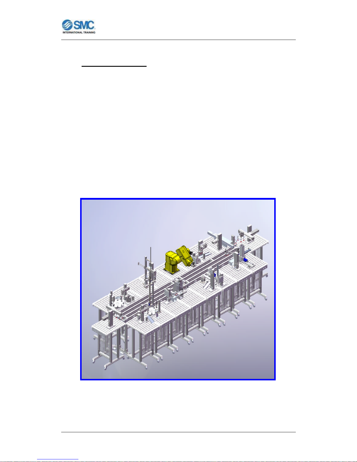
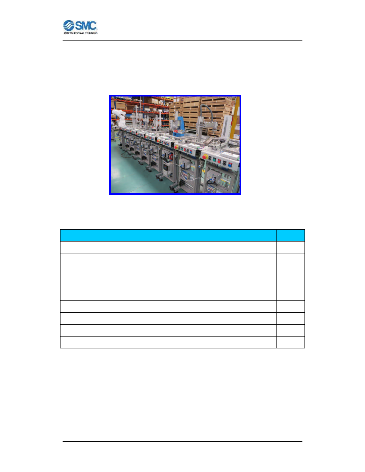
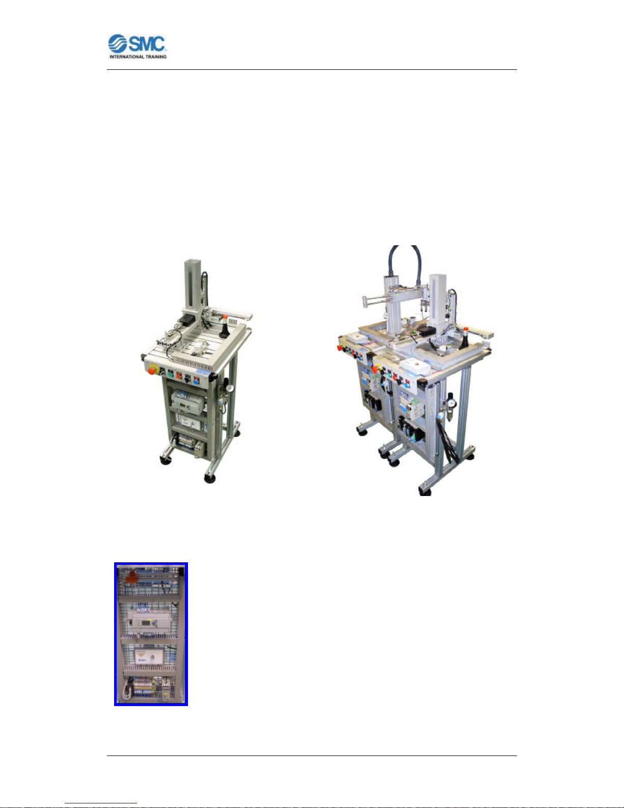
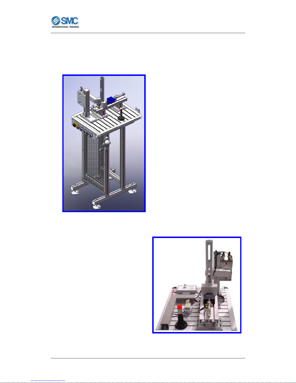
The FAS-200 system is the ideal answer to integral training in industrial
automation. It is fully modular and flexible equipment and in keeping with
industrial reality. The technologies included in its different assembly modules,
as well as the assembly process with several variants, allow the user to develop
the professional skills required by today’s automated industry.
FAS200 MODULES:
FAS200 is comprised of different stations, each performing a part of assembly
process.
Figure 1: System FAS200 with complete configuration.
Page 8
FLEXIBLE ASSEMBLY SYSTEM FAS200
User Manual for FAS200 - 6 -
STATION Qty.
FAS-201 Base Feeding/Verification module 1
FAS-202 Base Rejecting/Transfering module 1
FAS-203 Bearing Feeding/Transfering module 1
FAS-204 Bearing Measuring/Transfering module 1
FAS-205 Hydraulic Pressing module 1
FAS-206 Hydraulic Press Transfering module 1
FAS-207 Shaft classification module 1
FAS-208 Shaft Rejecting/Transfering module 1
FAS-209 Cover classification module 1
FAS-210 Cover Rejecting/Transfering module 1
FAS-211 Screws dispensing module 1
FAS-212 Screws insertion module 1
FAS-213 Robotized screwing module 1
FAS-214 Transfering and vision inspection module 1
FAS-215 After visual inspection rejecting module 1
FAS-216 Warehouse module 1
FAS-220 Pallet transfer module 2
FAS-230 Linear transfer for 4 modules 4
FAS-200 Empty module for future projects x
Page 9
FLEXIBLE ASSEMBLY SYSTEM FAS200
User Manual for FAS200 - 7 -
FAS200 CONFIGURATION:
The modules that make up the configuration of this system FAS200 are:
Figure 2: Example of system FAS200 with configuration of 8 modules.
STATION Qty.
FAS-201 Base Feeding/Verification module 1
FAS-202 Base Rejecting/Transfering module 1
FAS-203 Bearing Feeding/Transfering module 1
FAS-204 Bearing Measuring/Transfering module 1
FAS-209 Cover classification module 1
FAS-210 Cover Rejecting/Transfering module 1
FAS-213 Robotized screwing module 1
FAS-216 Warehouse module 1
FAS-230 Linear transfer for 4 modules 2
Page 10
FLEXIBLE ASSEMBLY SYSTEM FAS200
User Manual for FAS200 - 8 -
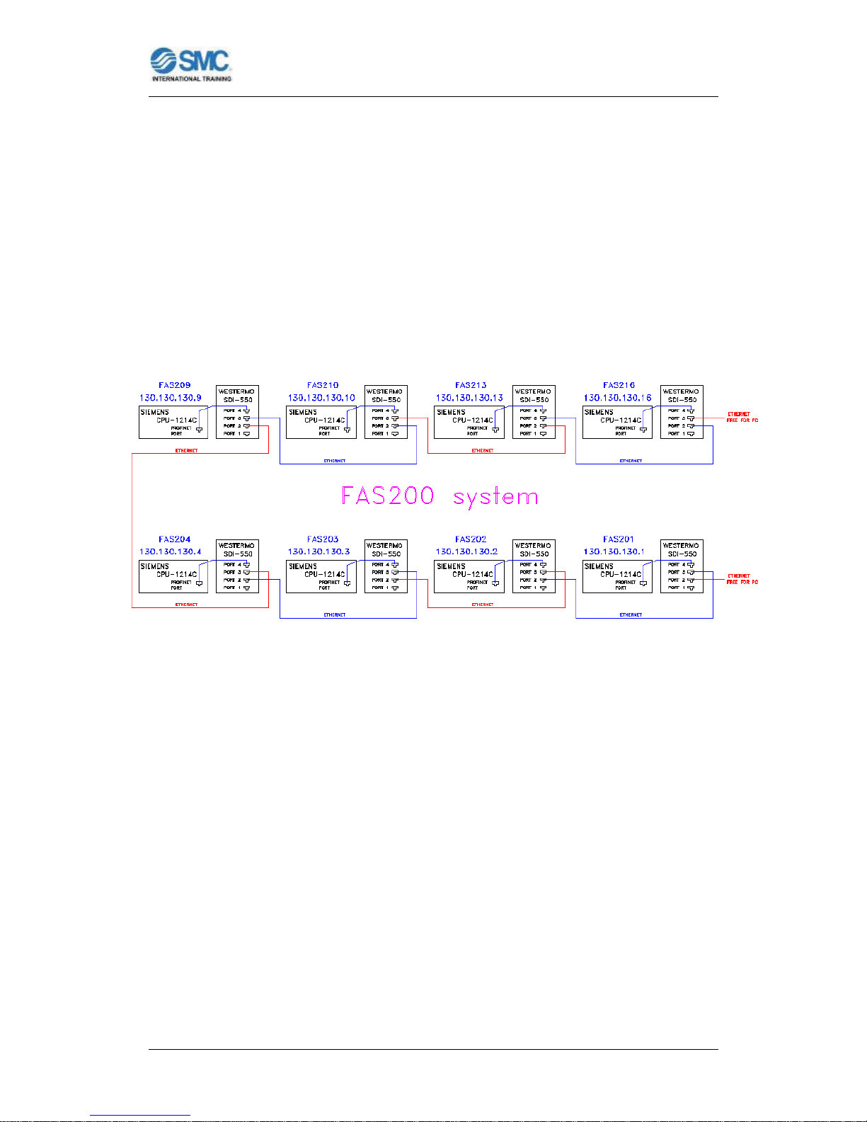
System FAS200
Number of modules: 8 modules
Number of modular conveyors: 2 units of linear transfer (for 4 modules)
Control: SIEMENS PLC of CPU 1214C serie.
Field and control network: ETHERNET.
Figure 3: Communication of the system FAS200 with configuration of 8 modules.
Page 11
FLEXIBLE ASSEMBLY SYSTEM FAS200
User Manual for FAS200 - 9 -
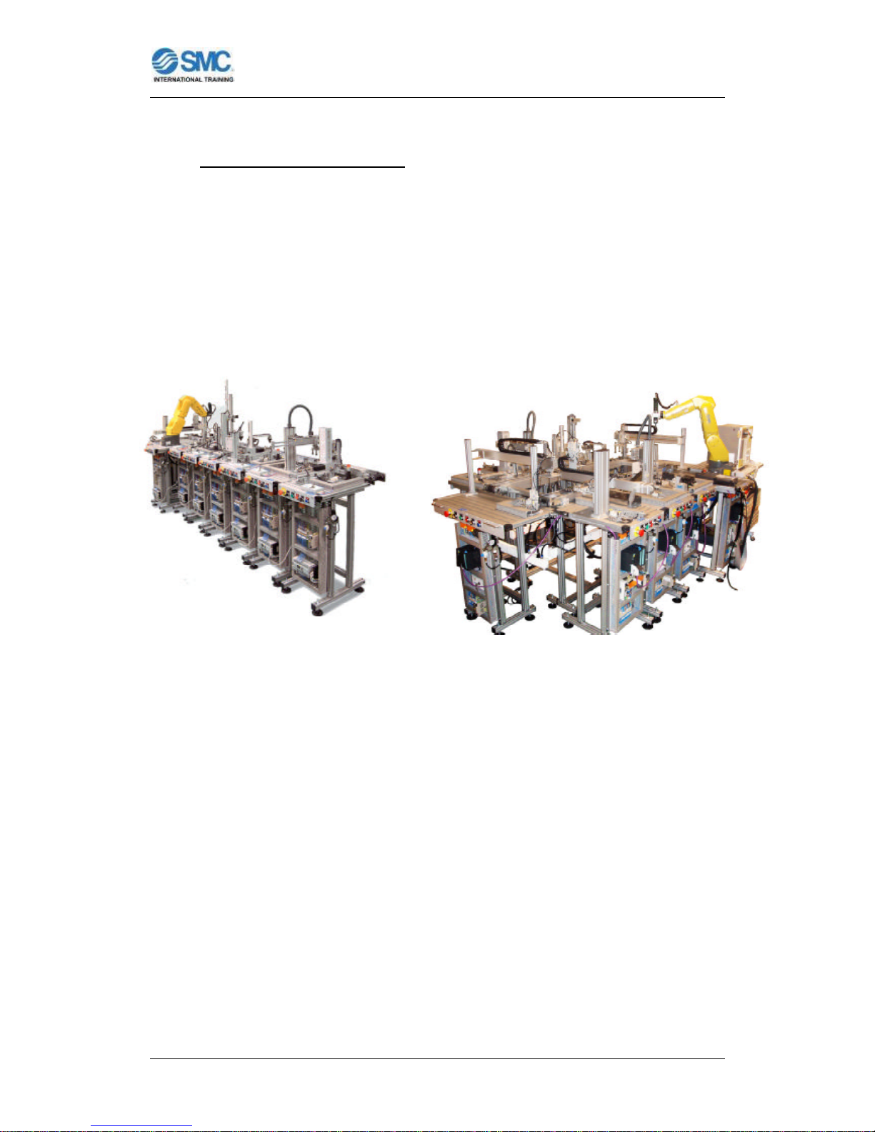
2. GENERAL OVERVIEW:
The flexible assembly system has been specially conceived for persons to
acquire professional capabilities in connection with the Occupational Groupings
of Electricity/ Electronics and Maintenance, such as:
- Installation, Electromechanical Maintenance and Line Transport.
- Industrial Equipment Maintenance.
- Automatic Control and Regulation Systems.
Figure 4: System FAS200 with different configurations.
It enables the development of various skills associated with pneumatic, electropneumatic, electrical, robotic and handling automatisms, programming and PLC
technologies, industrial communications, supervision, quality control and fault
diagnosis and repair. It also allows the study of a wide range of sensor types:
- Magnetic detectors.
- Inductive detectors.
- Optical fiber sensors.
- Photoelectric detectors.
- Capacitive detectors.
- Pressure and vacuum switches.
- Linear encoders….
Page 12
FLEXIBLE ASSEMBLY SYSTEM FAS200
User Manual for FAS200 - 10 -
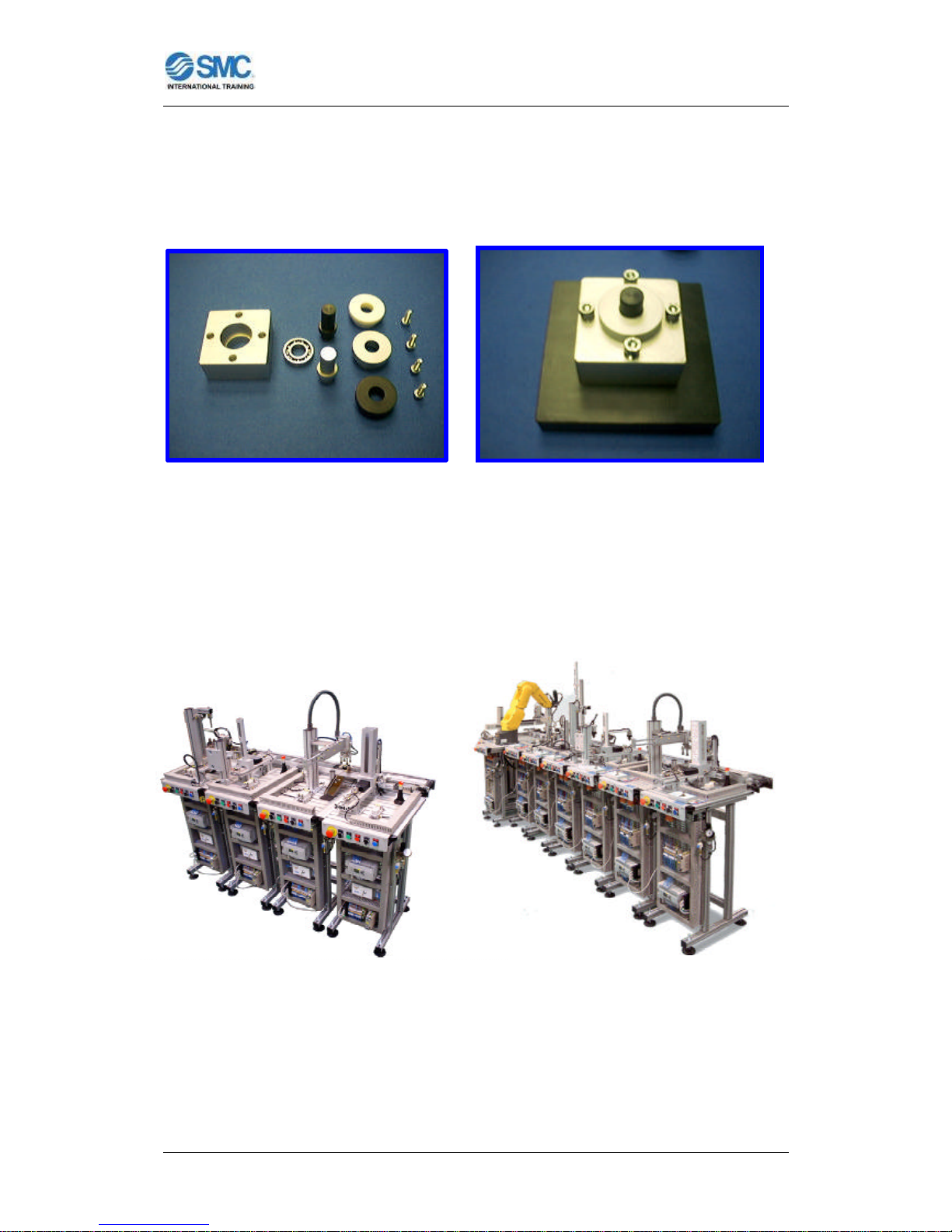
The system comprises a flexible automation cell which carries out an assembly
process involving a number of predetermined parts with a total of 24 different
possibilities.
Figure 5: Turning mechanism Figure 6: Turning mechanism
components
Parts are transported between the different modules by an automated linear
transfer with corresponding stoppers and precision lifters-positioners. Parts are
mounted on pallets.
Figure 7: Linear transfer for 4 modules. Figure 8: Linear transfer for 8 modules.
Page 13
FLEXIBLE ASSEMBLY SYSTEM FAS200
User Manual for FAS200 - 11 -
The process modules function either independently of the transport system, in
in single or couple modes, or integrated into it, in cell mode. The modules are
located in a side of the linear transfer, and may be withdrawn for re-positioning
in a different order (the repositioning of different modules of the system can
mean repositioning of stoppers, lifters-positioners and reprogramming of the
controllers of the system), moved for future extensions or work in
completely independent, in a single mode, or with its complementary module in
a couple mode (requiring reprogramming of the control).
Figure 9: FAS201 module a single mode. Figure 10: FAS201 and FAS202
modules in couple module (without any
linear transfer).
Each station has its own electrical panel, where the wiring
system and PLC are fully visible for study, while new elements
may be fitted to the panel if desired. In addition, students may
design and build their own controls with different PLCs and
subsequently integrate them in the station, thereby developing
a further series of skills envisaged in the Training Cycles for
those persons who form the target group for the Cell.
Figure 11: Electrical
panel of a module.
Page 14
FLEXIBLE ASSEMBLY SYSTEM FAS200
User Manual for FAS200 - 12 -
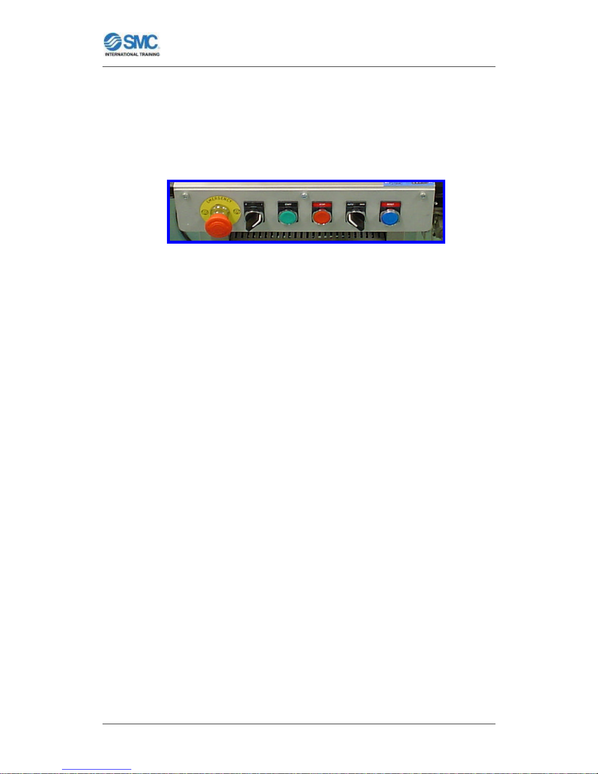
The front of each station incorporates the start, stop, step-bystep/continuous cycle and reset pushbuttons. In addition, the control
pushbuttons incorporate a main switch on/off and emergency pushbuttons for
emergency stops.
Figure 12: Control pushbuttons of a module.
The system is modular and may be extended, allowing future incorporation of
other process modules according to user needs.
The modules are mounted on aluminum sections, forming tables with a large
surface area and multiple slots to allow all types of extension and modification.
The assembly process performed (turning mechanism) is as follows:
Process A: Feed body or base to which the other parts are assembled and
verification of its orientation.
Process B: Pick and Place bearing and measurement of its height.
Process C: Press bearing in hydraulically.
Process D: Pick and Place shaft and verification of its orientation and material.
Process E: Pick and Place cover and verification of its orientation, material and
color.
Process F: Fit screws.
Process G: Robot screw driving.
Process H: Quality control by artificial vision.
Process I: Unloading, storage and palletization of final assembly
In addition to transport processes between modules or between linear
conveyors.
Page 15
FLEXIBLE ASSEMBLY SYSTEM FAS200
User Manual for FAS200 - 13 -
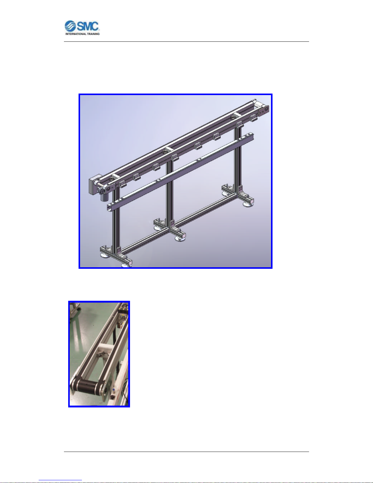
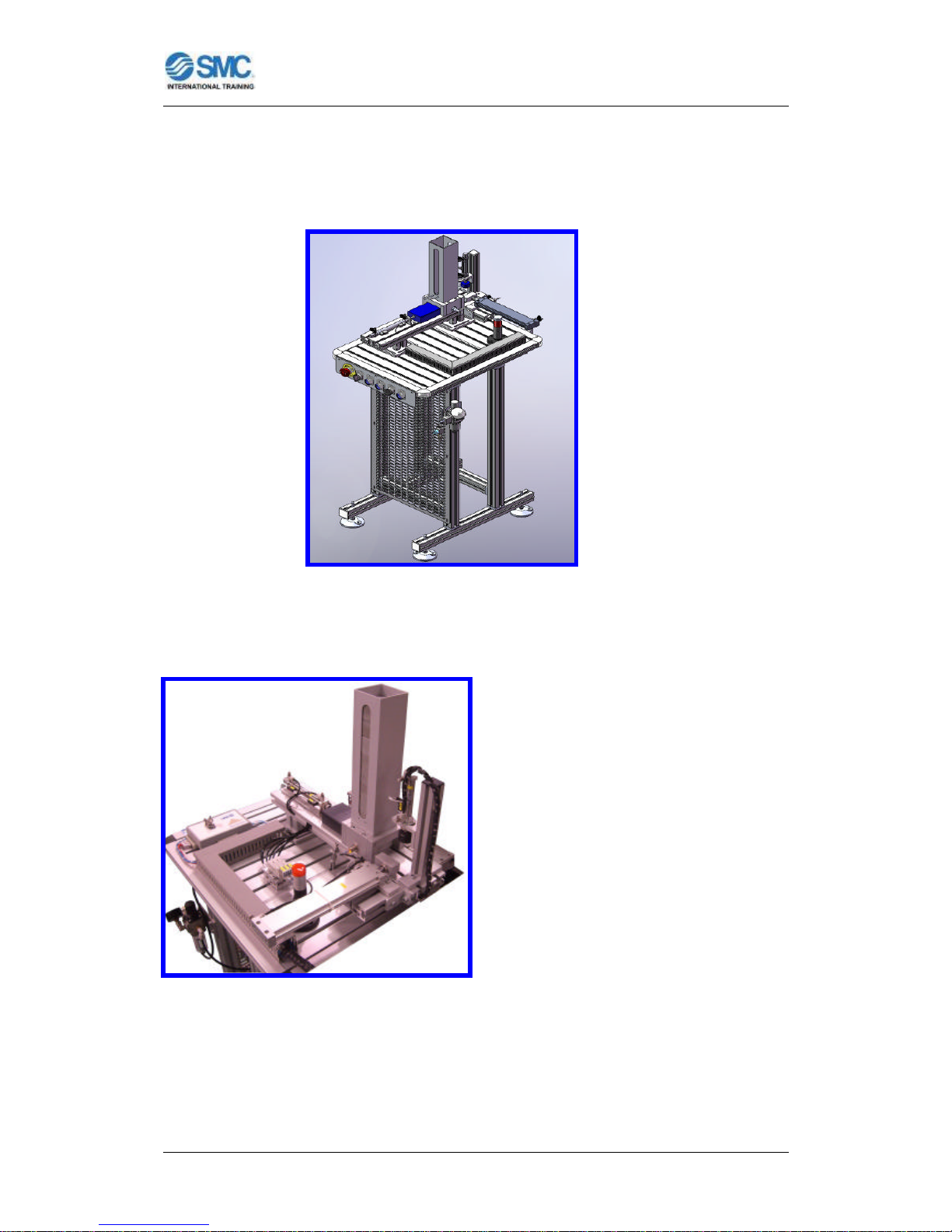
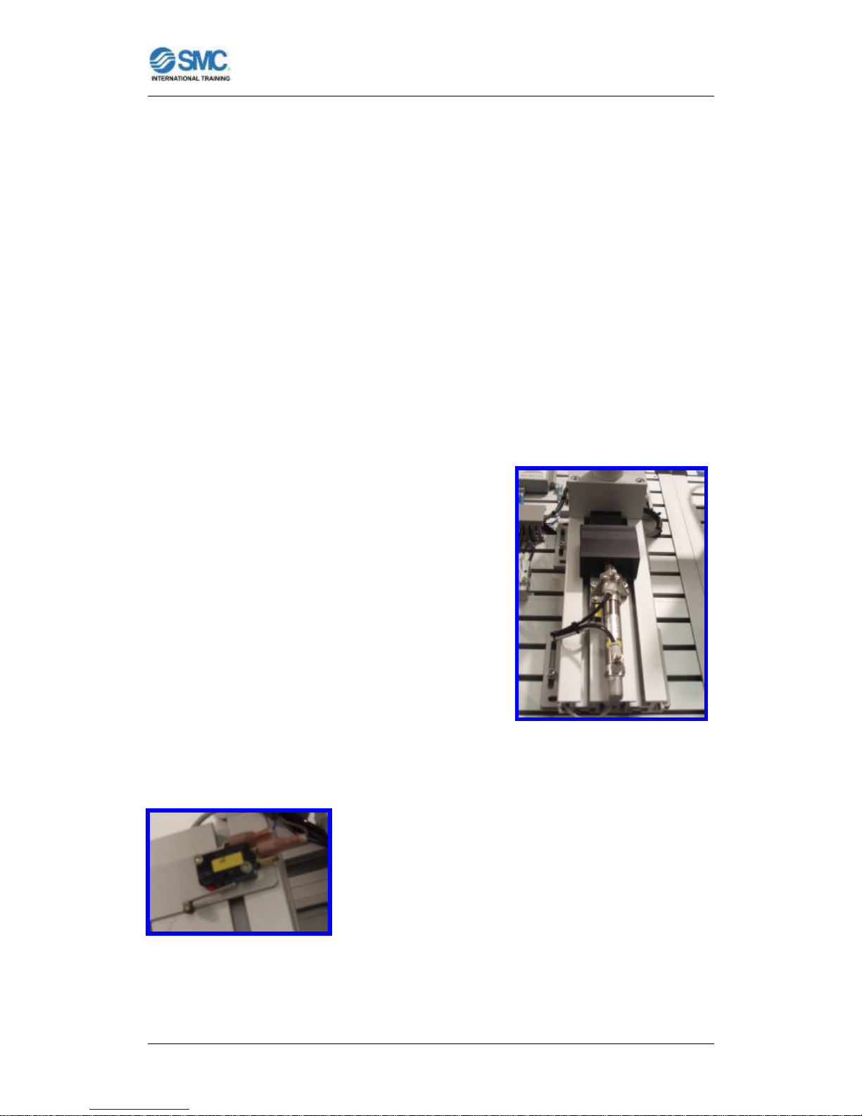
FAS-230 LINEAR TRANSFER MODULE: TRANSPORT SYSTEM
Figure 13: FAS230 Linear Transfer Module.
The transport system is composed by 2 meters long
lines admitting up to four modules each (2`9 meters long
lines admitting up to six modules each for special case)
which links the modules to facilitate the envisaged
assembly process.
Figure 14: Transport system.
Page 16
FLEXIBLE ASSEMBLY SYSTEM FAS200
User Manual for FAS200 - 14 -
Different layouts can be defined for future expansions. The transfer follows a
rectangular path or linear path. The master PLC controls and coordinates the
rest of the PLCs connected to the network and it is located in the “body feeding
and checking” station (FAS201 module).
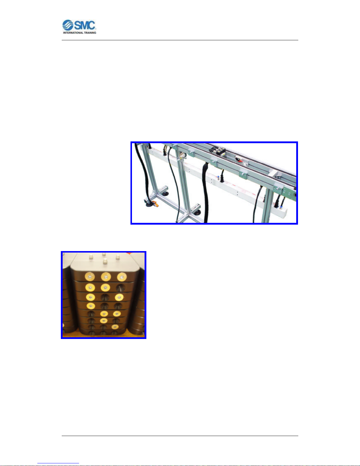
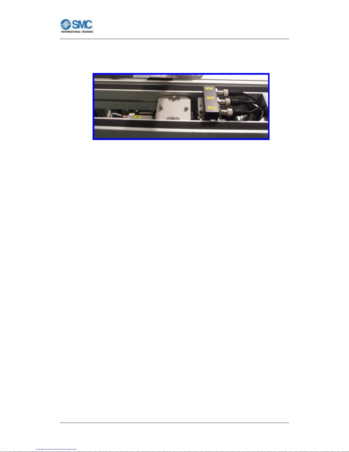
There is a longitudinal channel in one side of each module and of the linear
transfer to provide the electrical power connections and the air supply
connections between
the different stations
(and in some
configurations the
communication
connections).
Figure 15: Longitudinal channel for connections.
The modular transfer incorporates a pallet
assembly to transport parts and assemblies
across the handling stations. The pallets and the
transfer stoppers incorporate a binary coding
system using inductive detectors, which allow the
Control System to identify the position of each
pallet at any time.
Figure 16: Binary code on
the pallets.
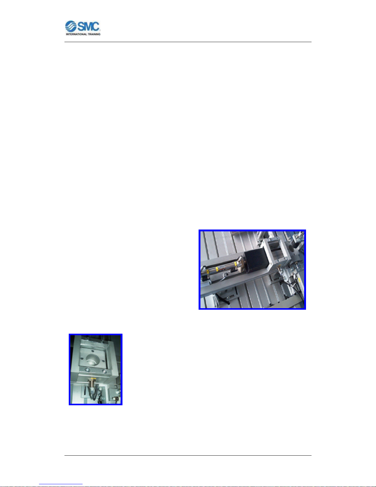
In front of some modules (which need to interact with the linear transfer
system), there is a mechanical end to stop the pallets, and, depending on the
particular process, a further series of elements for lifting, centering, turning, etc.
All these transport system actuators, stoppers, lifters, positioners and
Page 17
FLEXIBLE ASSEMBLY SYSTEM FAS200
User Manual for FAS200 - 15 -
pallet transfers are operated by a system of solenoid valves connected to each
module.
Figure 17: Stopper and lifter with microswitch and inductive detectors.
Both the pallet retention point and the relative position of the module within the
system FAS200 may be varied, making it simple to modify the distribution of the
component bases of the FAS-200. Although not recommended such
modifications as the system FAS200 is sent mechanically adjusted and
programmed to the specific distribution and any variation of the distribution
would also reprogram the control of the system.
TECHNICAL DATA: Modular transfer:
Dimensions (each transfer (for 4 modules)):
1 section 2000 x 130 mm. Height 970 mm.
Dimensions (each transfer (for 6 modules)):
1 section 2900 x 130 mm. Height 970 mm.
Drive (each transfer (for 4/6 modules)):
1 Motor 24 VDC HIWIN (AM1 M12029A1).
1 Power supply 24 VDC / 60 W OMRON (S8VK-G06024).
Composition:
Actuators (each 2 modules):
- 1 Compact double-acting cylinder Ø32, Stroke: 25mm (CQ2B32-25DXSE040). Controlled by 5/2 way monostable solenoid valve.
Page 18

FLEXIBLE ASSEMBLY SYSTEM FAS200
User Manual for FAS200 - 16 -
Actuators (some modules):
- 1 Compact double-acting cylinders with guide Ø16, Stroke: 30mm (MGPM1630Z), with flow regulators. Controlled by 5/2 way monostable solenoid valve.
- 1 Two-directions rotary table ?max: 90º (MSUB3-90S), with flow regulators.
Controlled by 5/2 way monostable solenoid valve.
Sensors (each 2 modules):
- 3 Inductive detectors OMRON (E2A-M12KS04-M1-B1).
- 1 Microswitch OMRON (V-166-1C5).
Page 19
FLEXIBLE ASSEMBLY SYSTEM FAS200
User Manual for FAS200 - 17 -
TROUB-200 FAULT SIMULATION SYSTEM
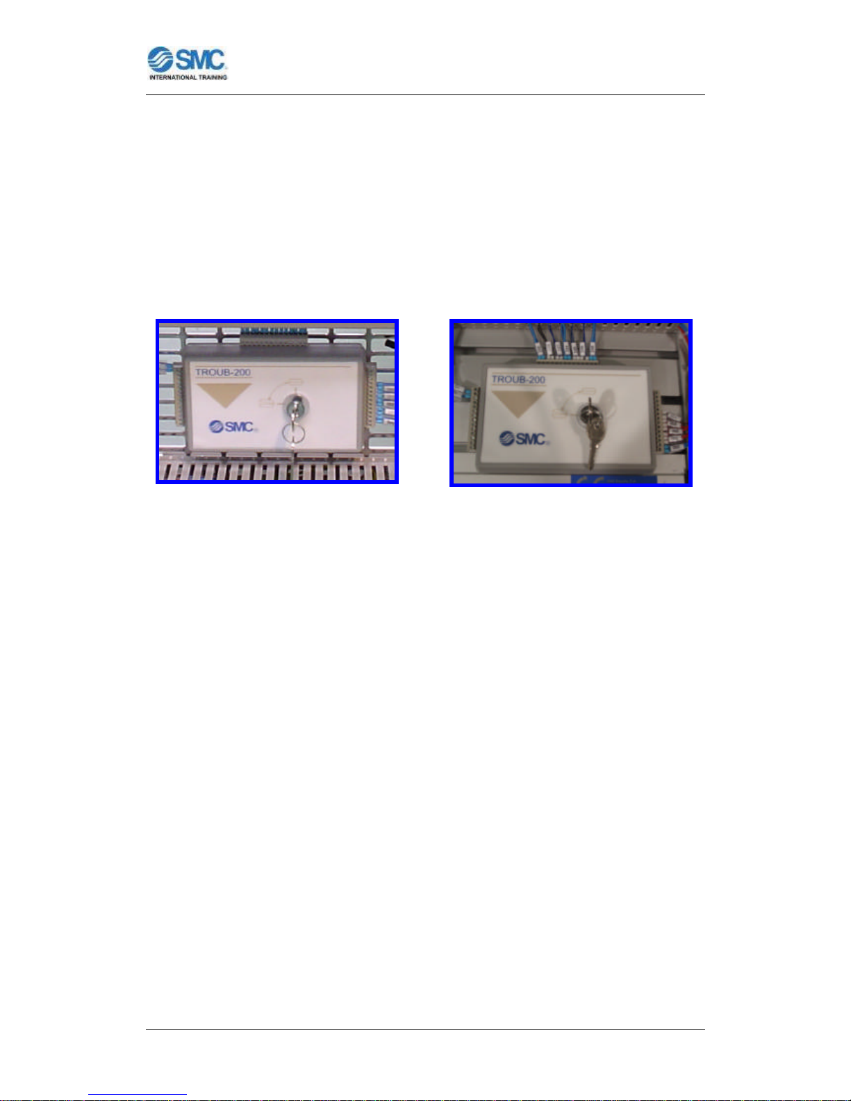
Most of the modules incorporate a Fault Simulation System TROUB-200 fitted
to the side of each module or in the electrical panel, depending of the
configuration.
Figure 18: TROUB-200 in the Figure 19: TROUB-200 in a side of
electrical panel. module.
The system consists of a lockable box containing 16 switches which, when
operated, cause a fault in the module.
In the Appendix A, there are more details about this Fault Simulation System,
with a series of tables, per module, where the error symptom, suspicious
components and the final faulty component can be found.
Page 20
FLEXIBLE ASSEMBLY SYSTEM FAS200
User Manual for FAS200 - 18 -
FAS-201 BASE FEEDING/VERIFICATION MODULE
Figure 20: FAS201 Base Feeding/Verification Module.
FUNCTION OF THE MODULE:
This first module feeds the body or
base which is the support for the
turning mechanism, verifies its
orientation and moves it to the final
position (loading position) located in
the transfer system of the next
module.
Figure 21: Manipulators of the first module.
This operation begins when the pallet is positioned opposite the second
module, held in a determined location by a stopper on the linear transfer.
Confirmation that the pallet is in the correct position is provided by a
Page 21
FLEXIBLE ASSEMBLY SYSTEM FAS200
User Manual for FAS200 - 19 -
microswitch which sends the appropriate signal to the PLC of the second
module which in turn sends the signal “start cycle” to the PLC of this first
module.
The confirmation of the body is in correct orientation is got by a pneumatic
cylinder like a checker turning on an internal flag of the PLC, signal used by this
PLC to send the signal “body OK” to the PLC of the next module.
INTEGRAL PARTS:
The first module, like the others, may be divided into a series of manipulators.
Each sub-division has been made by considering it as a set of components
which performs a specific operation within the whole process carried out at the
module.
• Body feeder:
The feeder which supplies the body is
of the gravity feed type, in that the
bodies are stored in a stack so that
when the bottom one is removed, the
next falls into place under the effect of
its own weight and that of the ones
above it.
Figure 22: Body feeder.
The body is extracted by a pneumatic cylinder which
pushes against a pusher shaped to match the profile of the
body. An inductive sensor is used to alert about lack of
bodies in the feeder.
Figure 23: Inductive sensor.
Page 22
FLEXIBLE ASSEMBLY SYSTEM FAS200
User Manual for FAS200 - 20 -
• Verification of position:
The body contains a housing in which the other
components are fitted. This housing must always be
facing upwards when the base is placed on the pallet
(in the next module). To check correct body
orientation, a check is made by a cylinder which
advances and inserts a cylindrical part in the body
housing. If the body is inverted, this part cannot enter
the housing, the cylinder cannot complete its stroke
and the magnetic detector on the cylinder is not
activated. A signal to this effect enters the PLC,
resulting in an indication that the position of the body
is incorrect.
Figure 24: Orientation checker.
• Movement to transfer point:
A pneumatic cylinder with a pusher at its end is used to situate the body at the
point from which it will be loaded on the pallet on the following module.
The cylinder is rectangular, to prevent the
pusher from turning.
Figure 25: Cylinder with a pusher.
TECHNICAL DATA:
Dimensions:
Table of slotted aluminium, 450 x 582 mm. Height 900 mm.
Air treatment unit:
Filter to 5 µm, pressure regulator and pressure gauge.
Page 23

FLEXIBLE ASSEMBLY SYSTEM FAS200
User Manual for FAS200 - 21 -
Control panel:
Start, stop, reset pushbuttons. Emergency stop button, main switch on/off,
mode selector (auto-man), no material indicator and error pilot indicator.
Composition of module manipulators:
Body feeder
Magazine capacity: 12 bodies.
Actuators:
- Double-acting pusher cylinder Ø16, Stroke: 100mm (CD85N16-100-B),
with flow regulators and initial-end position detectors. Controlled by 5/2 way
monostable solenoid valve.
Sensors:
- Reed type magnetic detectors (D-C73L).
- Inductive sensor OMRON (E2A-M12KS04-WP- B1).
Position verification
Actuators:
- Double-acting cylinders Ø12, Stroke: 50mm (CD85N12-50-A), with flow
regulators and end position detector. Controlled by 5/2 way monostable
solenoid valve.
Sensors:
- Reed type magnetic detector (D-A73CL).
Transfer manipulator
Actuators:
- Rectangular section pusher cylinder Ø25, Stroke: 200mm (MDUB25200DMZ), with flow regulators and end position detector. Controlled by 5/2 way
monostable solenoid valve.
Sensors:
- Reed type magnetic detector (D-A93L).
Page 24

FLEXIBLE ASSEMBLY SYSTEM FAS200
User Manual for FAS200 - 22 -
Electrical control panel:
- Mounted on perforated mesh.
- Accessible terminal plate with supply connections and coded I/Os.
- I/O station: 9 inputs, 5 outputs.
- Supply module: 24V/60W.
- PLC control:
• CPU with digital inputs/outputs.
• Communication module for PLC network connection.
Page 25
FLEXIBLE ASSEMBLY SYSTEM FAS200
User Manual for FAS200 - 23 -
FAS-202 BASE REJECTING/TRANSFERING MODULE
Figure 26: FAS202 Base Rejecting/Transfering Module.
FUNCTION OF THE MODULE:
This second module is
complementary to previous one. This
module rejects of incorrect body or
places the body on the pallet,
depending of the signal “body OK”
from the PLC of the preceding
module after verification of the base
orientation.
Figure 27: Manipulators of the second
module.
Page 26
FLEXIBLE ASSEMBLY SYSTEM FAS200
User Manual for FAS200 - 24 -
This operation begins when the pallet is positioned opposite the module, held in
a determined location by a stopper on the linear transfer, and when the PLC of
the first module sends the signal “end cycle” to the PLC of this second module.
INTEGRAL PARTS:
The second module, like the others, may be divided into a series of
manipulators. Each sub-division has been made by considering it as a set of
components which performs a specific operation within the whole process
carried out at the module.
• Rejection of incorrect body:
If the verification process shows
the orientation of the body to be
incorrect, a single-acting cylinder
moves it towards a ramp, leaving
the space clear for a new body.
Figure 28: Rejection cylinder.
• Placing body onto the pallet:
A two-cartesian axes manipulator is used to place the body
on the pallet that is waiting on the conveyor belt. The
horizontal axis is carried out by a dual rod cylinder/Double
rod and the vertical axis by a dual rod cylinder.
The terminal element is a vacuum system with a platform
with four suction cups (to absorb possible lack of alignment
in height).
Figure 29: Cartesian manipulator.
Page 27
FLEXIBLE ASSEMBLY SYSTEM FAS200
User Manual for FAS200 - 25 -
Suction is generated by a vacuum ejector fitted with a
vacuum switch which sends a signal to the PLC
indicating that the part has been correctly clamped.
Figure 30: Vacuum system.
TECHNICAL DATA:
Dimensions:
Table of slotted aluminium, 450 x 582 mm. Height 900 mm.
Air treatment unit:
Filter to 5 µm, pressure regulator and pressure gauge.
Control panel:
Start, stop, reset pushbuttons. Emergency stop button, main switch on/off,
mode selector (auto-man) and error pilot indicator.
Composition of module manipulators:
Inverted body rejection manipulator
Actuators:
- Single-acting ejection cylinder Ø10, Stroke: 15mm (CJPB10-15H6). Controlled
by 3/2 way monostable solenoid valve.
Pallet insertion module
Actuators:
- Horizontal axis: Parallel and dual rod cylinder Ø20, Stroke: 150mm
(CXSWM20-150-XB11), with flow regulators and initial-end position detectors.
Controlled by 5/2 way bistable solenoid valve.
Page 28

FLEXIBLE ASSEMBLY SYSTEM FAS200
User Manual for FAS200 - 26 -
- Vertical axis: Parallel rod cylinder Ø15, Stroke: 50mm (CXSM15-50), with flow
regulators and initial-end position detectors. Controlled by 5/2 way monostable
solenoid valve.
- Vacuum system: 4 telescopic suction cups Ø16 (ZPT16CNK10-B5-A10), with
ejector to generate vacuum (ZU07S). Controlled by 3/2 way bistable solenoid
valve.
Sensors:
- Reed type magnetic detectors (D-Z73L).
- Vacuum switch with PNP output (PS1100-R06L).
Electrical control panel:
- Mounted on perforated mesh.
- Accessible terminal plate with supply connections and coded I/Os.
- I/O station: 13 inputs, 8 outputs.
- Supply module: 24V/60W.
- PLC control:
• CPU with digital inputs/outputs.
• Communication module for PLC network connection.
Page 29
FLEXIBLE ASSEMBLY SYSTEM FAS200
User Manual for FAS200 - 27 -
FAS-203 BEARING FEEDING/TRANSFERING MODULE
Figure 31: FAS203 Bearing
Feeding/Transfering Module.
FUNCTION OF THE MODULE:
This third module feeds the bearing
which is going to be placed inside the
housing formed in the body by the next
module. Also this module transfer the
bearing to the measurement position
located on the next module, where the
height is measured to differentiate
between the two sizes of bearings
Figure 32: Manipulators of the third module.
Page 30
FLEXIBLE ASSEMBLY SYSTEM FAS200
User Manual for FAS200 - 28 -
This operation begins when the pallet is positioned opposite the fourth module,
held in a determined location by a stopper and a positioner-lifter on the linear
transfer. Confirmation that the pallet is in the correct position is provided by a
microswitch which sends the appropriate signal to the PLC of the fourth module
which in turn sends the signal “start cycle” to the PLC of this third module.
INTEGRAL PARTS:
The third module, like the others, may be divided into a series of manipulators.
Each sub-division has been made by considering it as a set of components
which performs a specific operation within the whole process carried out at the
module.
• Bearing feeder:
The feeder which supplies the bearing is of the
gravity feed type, in that the bearings are
stored in a column so that when the bottom
one is removed (the bearing is extracted at the
moment the cycle starts), the next falls into place
under the effect of its own weight and that of the
ones above it.
F
Figure 33: Bearing feeder.
In this case, there is a bearing presence sensor in the form of a microswitch
which allows the PLC to verify that a bearing really
has been extracted following the feeding
procedure. This makes it possible to determine
when the bearings loaded in the feeder have run
out.
Figure 34: Microswitch.
Page 31

FLEXIBLE ASSEMBLY SYSTEM FAS200
User Manual for FAS200 - 29 -
• Transfer to the measurement position:
A manipulator is used to move the bearing from the feeding position (in this third
module) to the place where the height measuring operation is to be performed
(in next fourth module). The manipulator uses a rack and pinion type rotary
actuator which describes an angle of 180º.
An arm is attached to the rotary actuator
to move a two-finger parallel-opening
gripper which grips the inner part of the
bearing. This arm houses a mechanism
consisting of a toothed belt and two
pinions, the purpose of which is to keep
the gripper orientation throughout the
turning movement, so that it can reach the
measuring point in horizontal position.
Figure 35: Transfer manipulator.
TECHNICAL DATA:
Dimensions:
Table of slotted aluminium , 450 x 582 mm. Height 900 mm.
Air treatment unit:
Filter to 5 µm, pressure regulator and pressure gauge.
Control panel:
Start, stop, reset pushbuttons. Emergency stop button, main switch on/off,
mode selector (auto-man), no material indicator and error pilot indicator.
Composition of module manipulators:
Bearing feeder
Magazine capacity: 38 bearings
Page 32

FLEXIBLE ASSEMBLY SYSTEM FAS200
User Manual for FAS200 - 30 -
Actuators:
- Double-acting pusher cylinder Ø16, Stroke: 100mm (CD85N16-50-B),
with flow regulators and end position detector. Controlled by 5/2 way
monostable solenoid valve.
Sensors:
- Reed type magnetic detector (D-C73L).
- Presence detector: Microswitch OMRON (V-166-1C5).
Measurement position transfer manipulator
Actuators:
- Rotary actuator: Double rack and pinion Ø50, ? max: 180º (MSQB50A), with
flow regulators and 0º, 90º and 180º position detectors. Controlled by 5/3 way
solenoid valve, mid position closed.
- Holding arm: Two-finger parallel-opening gripper (MHK2-16D). Controlled by
5/2 way bistable solenoid valve.
Sensors:
- Reed type magnetic detectors (D-A93L).
Electrical control panel:
- Mounted on perforated mesh.
- Accessible terminal plate with supply connections and coded I/Os.
- I/O station: 9 inputs, 7 outputs.
- Supply module: 24V/60W.
- PLC control:
• CPU with digital inputs/outputs.
• Communication module for PLC network connection.
Page 33

FLEXIBLE ASSEMBLY SYSTEM FAS200
User Manual for FAS200 - 31 -
FAS-204 BEARING MEASURING/TRANSFERING MODULE
Figure 36: FAS204 Bearing
Measuring/Transfering Module.
FUNCTION OF THE MODULE:
This fourth module is complementary to
previous one. Is in this module where the
height is measured to differentiate between
the two sizes of bearings.
Figure 37: Manipulators of the fourth module.
Page 34

FLEXIBLE ASSEMBLY SYSTEM FAS200
User Manual for FAS200 - 32 -
This module rejects the bearing or places it inside the housing of the body on
the pallet, depending of the signal “tall bearing” or “short bearing”. The
confirmation of the bearing has got the correct height is got by a linear
potentiometer like a measurer turning on an internal flag of the PLC, signal “tall
bearing” or “short bearing”.
This operation begins when the pallet is positioned opposite the module, held in
a determined location by a stopper and a positioner-lifter on the linear transfer,
and when the PLC of the third module sends the signal “end cycle” to the PLC
of this fourth module.
The task of placing the bearing is performed on the pallet brought by the belt
conveyor and carrying the body fed and assembled by the previous modules.
The bearing fitting operation requires the pallet carrying the body to be precisely
situated in a predetermined place. To achieve this precision, once the pallet has
been retained by a stopper, it is lifted by a pneumatic cylinder and centred at
the same time by four pins which fit inside housings formed for this purpose in
the bottom of the pallet.
INTEGRAL PARTS
The fourth module, like the others, may be divided into a series of manipulators.
Each sub-division has been made by considering it as a set of components
which performs a specific operation within the whole process carried out at the
module.
• Height measurement:
As the module allows the possibility of feeding bearings of differing heights, a
measuring manipulator is included to measure the height and to differentiate
between them.
Page 35

FLEXIBLE ASSEMBLY SYSTEM FAS200
User Manual for FAS200 - 33 -
The bearing is deposited on a
platform, with a centering device
operated by a pneumatic
cylinder which locates it at a very
precise position, that is needed to
perform the measurement of the height
correctly.
Figure 38: Measuring manipulator.
This platform is lifted by a rodless pneumatic cylinder such that the bearing
contacts with a touch trigger and gives a height reading. The touch trigger
consists of a linear potentiometer with an output processed via an analogue
module included in the PLC.
After measurement, the lifter returns to its original position. Then, in case the
height does not correspond to the selected one, a cylinder pushes the bearing
towards a ramp.
• Bearing insertion:
The final operation is performed by a
manipulator comprising a rotary-linear
system with an arm to which a two -finger
gripper has been fitted. After picking up
the bearing, the arm goes up, turns
through 180º and then goes down again
to insert the bearing in the housing of the
body.
Figure 39: Insertion manipulator.
Page 36

FLEXIBLE ASSEMBLY SYSTEM FAS200
User Manual for FAS200 - 34 -
TECHNICAL DATA:
Dimensions:
Table of slotted aluminium , 450 x 582 mm. Height 900 mm.
Air treatment unit:
Filter to 5 µm, pressure regulator and pressure gauge.
Control panel:
Start, stop, reset pushbuttons. Emergency stop button, main switch on/off,
mode selector (auto-man) and error pilot indicator.
Composition of module manipulators:
Height measuring manipulator
Actuators:
- Centering device: Compact single-acting cylinder Ø12, Stroke: 5mm
(CQ2B12-5S). Controlled by 3/2 way monostable solenoid valve.
- Vertical axis: Rodless cylinder Ø16, Stroke: 250mm (MY1M16G-250), with
flow regulators and initial-end position detectors. Controlled by 5/2 way bistable
solenoid valve.
- Incorrect bearing rejection: Double-acting cylinder Ø10, Stroke: 40mm
(CD85N10-40-B), with flow regulators. Controlled by 5/2 way monostable
solenoid valve.
Sensors:
- Reed type magnetic detectors (D-A93L).
- Linear potentiometer GEFRAN (PY-2-F-025-S02M).
Bearing insertion manipulator
Actuators:
- Compact double-acting cylinder with guide Ø16, Stroke: 30mm (MGPM16-30),
with flow regulators and initial-end position detectors. Controlled by 5/2 way
monostable solenoid valves.
Page 37

FLEXIBLE ASSEMBLY SYSTEM FAS200
User Manual for FAS200 - 35 -
- Rotary actuator: Double rack and pinion type Ø20, ? max: 180º (MSQXB20A),
with flow regulators and two position detectors. Controlled by 5/2 way
monostable solenoid valves.
- Holding arm: Two-finger parallel-opening gripper (MHK2-16D). Controlled by
5/2 way bistable solenoid valve.
Sensors:
- Reed type magnetic detectors (D-A93L).
Electrical control panel:
- Mounted on perforated mesh.
- Accessible terminal plate with supply connections and coded I/Os.
- I/O station: 14 digital inputs, 1 analogue input, 11 outputs.
- Supply module: 24V/60W.
- PLC control:
• CPU with digital inputs/outputs.
• Analogue inputs card.
• Communication module for PLC network connection.
Page 38

FLEXIBLE ASSEMBLY SYSTEM FAS200
User Manual for FAS200 - 36 -
FAS-205 HYDRAULIC PRESSING MODULE
Figure 40: FAS205 Hydraulic Pressing
Module.
FUNCTION OF THE MODULE:
Following the bearing insertion operation
performed by the preceding modules, this fifth
module carries out the task of pressing the
bearing firmly into the body to fix it securely. In
actual fact, this pressing operation is not
actually carried out; instead, it is only
simulated so that the finished assembly may
be dismantled easily and the component parts
reused.
Figure 41: Manipulators of the fifth module.
Page 39

FLEXIBLE ASSEMBLY SYSTEM FAS200
User Manual for FAS200 - 37 -
In spite of this, the components included are all industrial grade and similar to
those used in numerous hydraulic applications. They allow the study of
systems based on hydraulic technology which incorporate real components
integrated in an authentic application.
A complete hydraulic unit as required to supply the press cylinder with high
pressure oil is installed under the table, avoiding the need for any additional
hydraulic installation other than the electrical and pneumatic take-offs from the
central transfer.
This operation begins when the pallet is positioned opposite the sixth module,
held in a determined location by a stopper on the linear transfer. Confirmation
that the pallet is in the correct position is provided by a microswitch which sends
the appropriate signal to the PLC of the sixth module which in turn sends the
signal “start cycle” to the PLC of this fifth module.
INTEGRAL PARTS:
The fifth module, like the others, may be divided into a series of manipulators.
Each sub-division has been made by considering it as a set of components
which performs a specific operation within the whole process carried out at the
module.
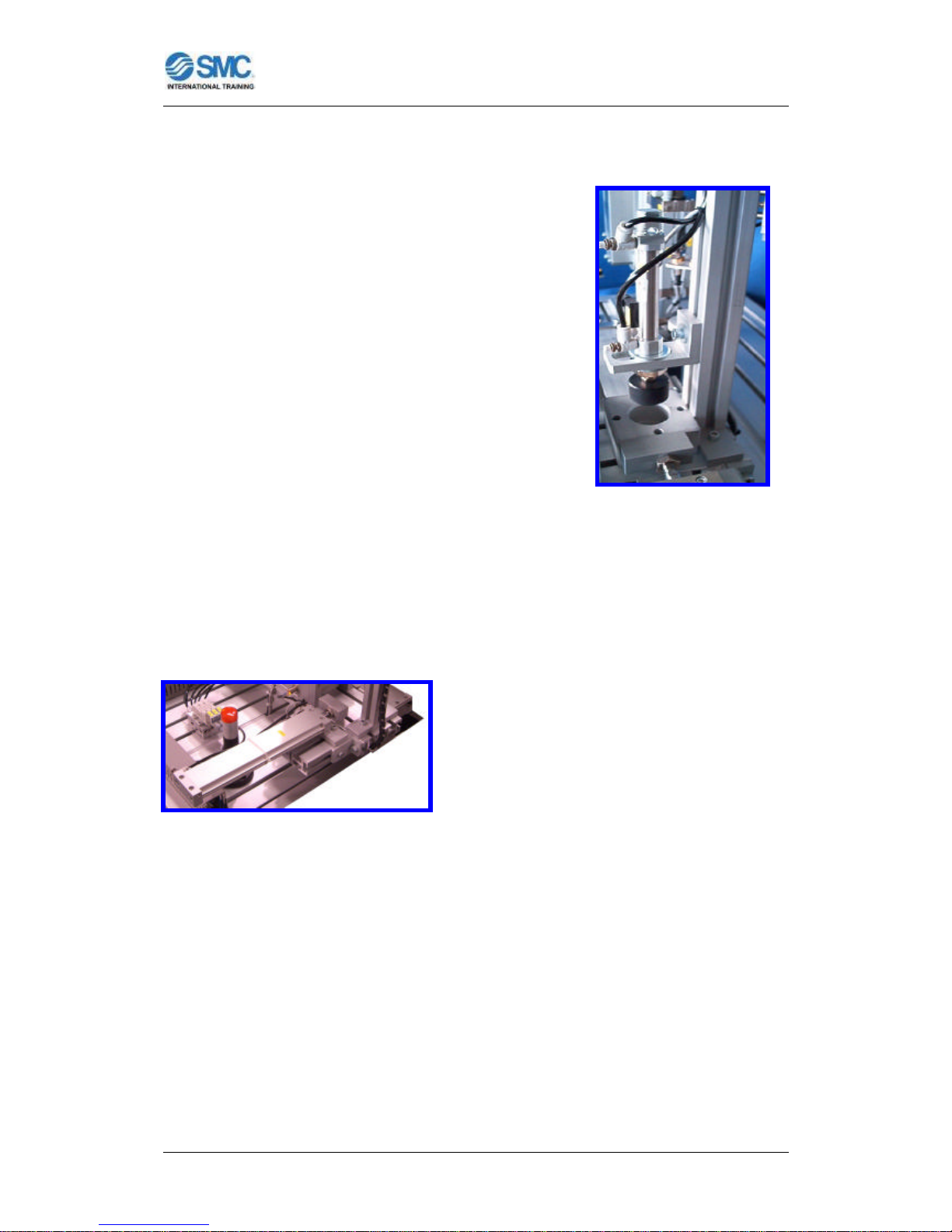
• Pressing the bearing:
When the body with the bearing inside has been positioned under the
hydraulic cylinder, a protective screen operated by a pneumatic cylinder drops
down. This protects the user against any risk of accident, and also
demonstrates a safety device widely used in this type of application. Also
includes other elements such as a safety switch and a safety relay, being able
to study the implementation of the safety in automation.
Page 40

FLEXIBLE ASSEMBLY SYSTEM FAS200
User Manual for FAS200 - 38 -
By means of a hydraulic 4/3 way directional
control valve, the pressing cylinder now exerts
a force which may be regulated using the
pressure limiting valve incorporated in the
hydraulic unit. After pressing, the cylinder
returns to its original position, the screen is
lifted and the assembly is pushed to the
unloading position.
Figure 42: Pressing of bearing.
• Feeder/Extractor of the press:
The body to be fed in to the press is deposited on a platform (of the sixth
module) fitted with two double-acting pneumatic cylinders. The first one (in the
sixth module) effects the transfer from the loading/unloading point to the
press, while the second one (in this
fifth module) carries out the reverse
operation following the pressing
operation.
Figure 43: Extraction cylinder from the
press.
Page 41

FLEXIBLE ASSEMBLY SYSTEM FAS200
User Manual for FAS200 - 39 -
TECHNICAL DATA:
Dimensions:
Table of slotted aluminium, 450 x 600 mm. Height 900 mm.
Air treatment unit:
Filter to 5 µm, pressure regulator and pressure gauge.
Control panel:
Start, stop, reset pushbuttons. Emergency stop button, main switch on/off,
mode selector (auto-man) and error pilot indicator.
Composition of module manipulators:
Bearing pressing manipulation
Actuators:
- Protector: Double-acting parallel rod cylinder Ø15, Stroke: 100mm (CXSM15-
100), with flow regulators and end position detector. Controlled by 5/2 way
monostable solenoid valve.
- Pressing: Compact double-acting hydraulic cylinder Ø40, Stroke: 50mm
(CHDKGB40-50M), with flow regulators and initial-middle-end position
detectors. Controlled by 4/3 way solenoid valve, mid position A-B closed and PT connected.
Sensors:
- Reed type magnetic detectors (D-Z73L).
Press extraction manipulation
Actuators:
- Double-acting pusher cylinders Ø12, Stroke: 125mm (CD85N12-125A), with
flow regulators and initial-end of stroke position detectors. Controlled by 5/2 way
monostable solenoid valves.
Sensors:
- Reed type magnetic detectors (D-A73CL).
Page 42

FLEXIBLE ASSEMBLY SYSTEM FAS200
User Manual for FAS200 - 40 -
Electrical control panel:
- Mounted on perforated mesh.
- Accessible terminal plate with supply connections and coded I/Os.
- I/O station: 13 inputs, 6 outputs.
- Supply module: 24V/60W.
- Safety relay with safety switch.
- PLC control:
• CPU with digital inputs/outputs.
• Communication module for PLC network connection.
Hydraulic unit:
- Three-phase motor 230/400V 0.50CV 1450rpm.
- Pressure gauge.
- Pressure limiter.
Page 43

FLEXIBLE ASSEMBLY SYSTEM FAS200
User Manual for FAS200 - 41 -
FAS-206 HYDRAULIC PRESS TRAN SFERING MODULE
Figure 44: FAS206 Hydraulic Press Transfering Module.
FUNCTION OF THE MODULE:
This sixth module is complementary to
previous one. Is in this module where the
base-bearing assembly is transfered from the
pallet of the lineal conveyor to the platform of
this module, and then from this platform to the
hydraulic press of the previous module.
Figure 45: Manipulators of the sixth module.
Page 44

FLEXIBLE ASSEMBLY SYSTEM FAS200
User Manual for FAS200 - 42 -
This operation begins when the pallet is positioned opposite the module, held in
a determined location by a stopper on the linear transfer, and when the PLC of
the fifth module sends the signal “end cycle” to the PLC of this sixth module.
INTEGRAL PARTS
The sixth module, like the others, may be divided into a series of manipulators.
Each sub-division has been made by considering it as a set of components
which performs a specific operation within the whole process carried out at the
module.
• Insertion / extraction of assembly:
The first operation consists of moving
the body with the bearing inside it from
the pallet retained at the linear transfer
to an unloading point inside the module.
This handling, and the reverse process
of unloading following pressing, are
performed by a pneumatic rotary
actuator.
Figure 46: Insertion/extraction of assembly
This actuator incorporates an arm with a set of four suction cups at its end,
whose job is to hold the part by means of an internal vacuum generated by an
ejector. To keep the body permanently horizontal throughout the turning
movement, this arm incorporates a pinion and toothed belt mechanism similar
to that used at the bearing insertion station.
• Feeder/Extractor of the press:
The body to be fed in to the press is deposited on a platform (of this sixth
module) fitted with two double-acting pneumatic cylinders. The first one (in the
sixth module) effects the transfer from the loading/unloading point to the
press, while the second one (in this fifth module) carries out the reverse
operation following the pressing operation.
Page 45

FLEXIBLE ASSEMBLY SYSTEM FAS200
User Manual for FAS200 - 43 -
Figure 47: Feed cylinder to the press.
TECHNICAL DATA:
Dimensions:
Table of slotted aluminium, 450 x 600 mm. Height 900 mm.
Air treatment unit:
Filter to 5 µm, pressure regulator and pressure gauge.
Control panel:
Start, stop, reset pushbuttons. Emergency stop button, main switch on/off,
mode selector (auto-man) and error pilot indicator.
Composition of module manipulators:
Assembly insertion/extraction manipulator
Actuators:
- Rotary actuator: Double rack and pinion type Ø50, ? max:180º (MSQB50A),
with flow regulators and 0º, 90º and 180º position detectors. Controlled by 5/3
way solenoid valve, mid position closed.
- Holding arm: 4 Suction cups Ø16 (ZPT16UN-B5), with ejector to generate
vacuum (ZU07S). Controlled by 3/2 way bistable solenoid valve.
Sensors:
- Reed type magnetic detectors (D-A93L).
- Vacuum switch PNP output (PS-1100-R06L).
Page 46

FLEXIBLE ASSEMBLY SYSTEM FAS200
User Manual for FAS200 - 44 -
Press feed manipulation
Actuators:
- Double-acting pusher cylinders Ø12, Stroke: 125mm (CD85N12-125A), with
flow regulators and initial-end of stroke position detectors. Controlled by 5/2 way
monostable solenoid valves.
Sensors:
- Reed type magnetic detectors (D-A73CL).
Electrical control panel:
- Mounted on perforated mesh.
- Accessible terminal plate with supply connections and coded I/Os.
- I/O station: 14 digital inputs, 7 outputs.
- Supply module: 24V/60W.
- PLC control:
• CPU with digital inputs/outputs.
• Communication module for PLC network connection.
Page 47

FLEXIBLE ASSEMBLY SYSTEM FAS200
User Manual for FAS200 - 45 -
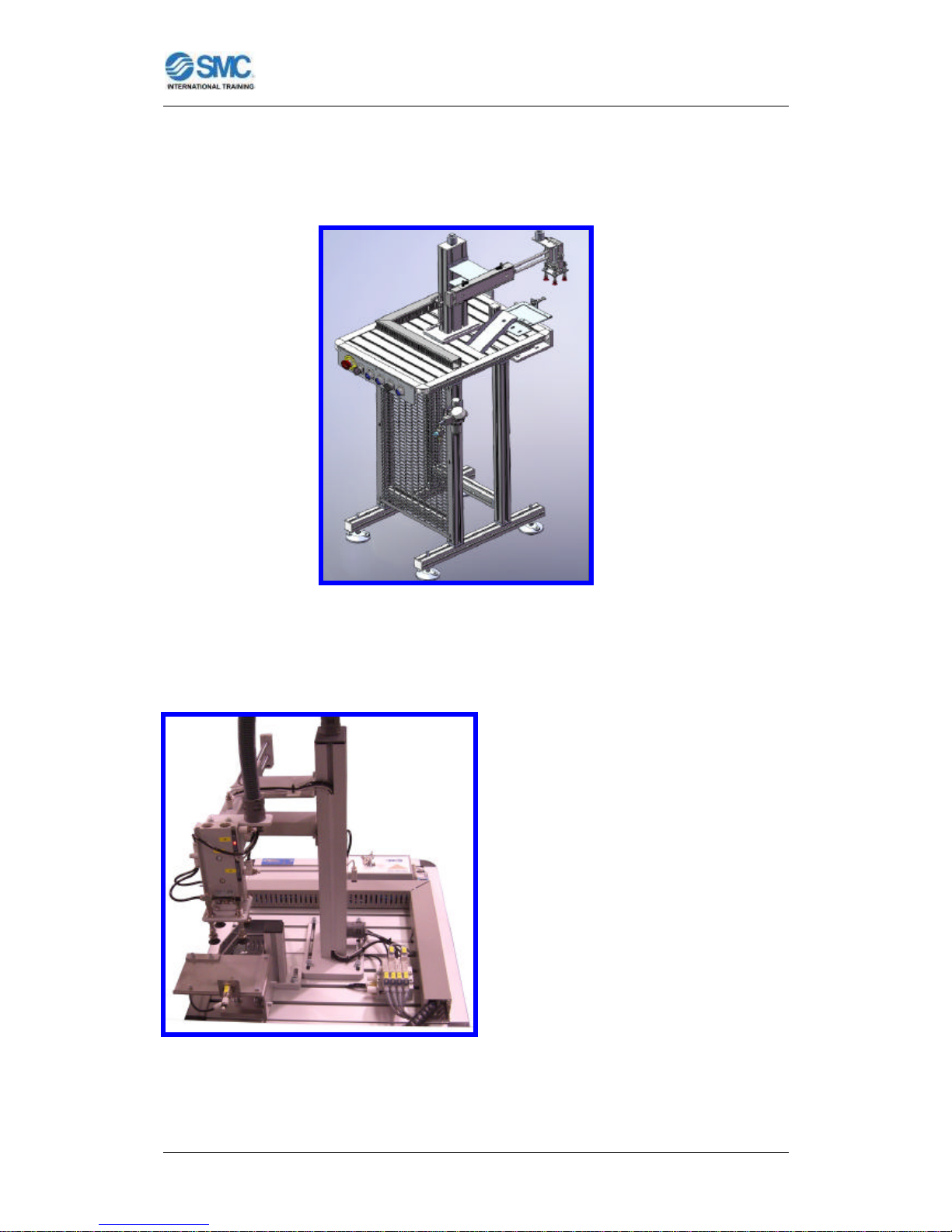
FAS-207 SHAFT CLASSIFICATION MODULE
Figure 48: FAS207 Shaft
Classification Module.
FUNCTION OF THE MODULE:
This module follows the process needed to insert a shaft into the bearing fitted
at one of the previous modules.
The need for appropriate checks to determine which
type of shaft is to be assembled at each module cycle
means that this module is one of the most complex in
terms of the operations to be carried out. It is also
essential that the module control coordinates part
selection operations in accordance with the
commands supplied by the master responsible for
production management in the FAS-200.
Figure 49: Manipulators of this module.
Page 48

FLEXIBLE ASSEMBLY SYSTEM FAS200
User Manual for FAS200 - 46 -
Because of this, this module represents an increase in flexibility in that it allows
variety in the assemblies put together, in the form of being able to fit shafts of
different materials; aluminium or nylon.
The existence of these variants means that the extra operations of checking the
type of material and extracting ones which are not of the desired material are
added to the normal operations of feeding, handling and insertion.
This seventh module feeds the shaft which will be inserted inside of the bearing
of the turning mechanism, and verifies its material and orientation. Then, the
next module rejects the shaft or places it inside the housing of the body on the
pallet, depending of the signals “metal shaft” and “plastic shaft” and the
orientation of the shaft.
The confirmation of the presence, the orientation and the material of the shaft is
got by some sensors (an inductive detector, a capacitive detector and a
pneumatic cylinder with magnetic detector at the end of its stroke) turning on
some internal flags of the PLC, the previously mentioned signals.
This operation begins when the pallet is positioned opposite the eighth module,
held in a determined location by a stopper on the linear transfer. Confirmation
that the pallet is in the correct position is provided by a microswitch which sends
the appropriate signal to the PLC of the eighth module which in turn sends the
signal “start cycle” to the PLC of this seventh module.
INTEGRAL PARTS:
The seventh module, like the others, may be divided into a series of
manipulators. Each sub-division has been made by considering it as a set of
components which performs a specific operation within the whole process
carried out at the module.
Page 49

FLEXIBLE ASSEMBLY SYSTEM FAS200
User Manual for FAS200 - 47 -
• Index plate:
This element is used as a system of alternating rotary movement, in the
sense that each turning movement
moves the plate round by a number
of degrees equal to the
circumference divided by the
number of defined positions. In this
case, it is a plate of 8 different
positions.
Figure 50: Index plate.
To achieve this effect, the system
incorporates a pneumatic pusher cylinder with
back and forth movement giving the required
angular advance.
Figure 51: Pusher cylinder.
There are a further two stop cylinders which function alternately, one moving
which holds the plate during the turn, and another fixed cylinder which locks the
plate in position when movement has ceased. In this way, the plate is held
firmly and the pusher cylinder can return to its initial position to await a new
cycle.
• Shaft feeder:
The shafts stored in a gravity type feeder are deposited on the first plate
position via a step-by-step feed system involving two pneumatic cylinders.
These cylinders are in a permanent counterpoise position, so that while the
lower one releases the next shaft from the feeder, the upper one holds the rest
in place.
Page 50

FLEXIBLE ASSEMBLY SYSTEM FAS200
User Manual for FAS200 - 48 -
Figure 52: Shaft feeder.
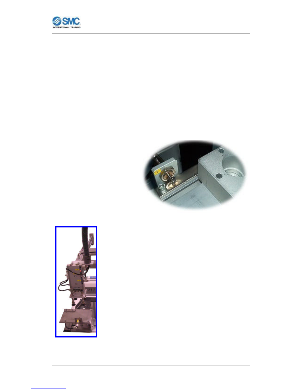
• Shaft orientation checker:
The shaft is not symmetrical and must therefore be mounted on the assembly
in a particular position and orientation.
The shaft is measured to check whether it has been
correctly inserted. A pneumatic cylinder fitted with
magnetic detector registers whether contact is
made with the shaft during outstroking, or whether
the cylinder is able to reach the end of its travel if
the shaft is not in its proper orientation.
Figure 53: Shaft orientation checker.
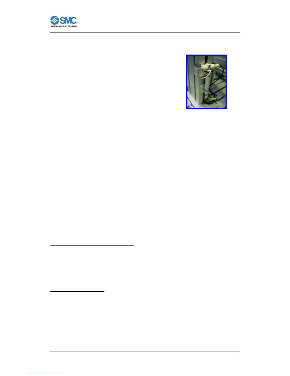
• Material detection position:
As described above, this module offers the possibility of working with
aluminium or black nylon. To differentiate these two types and detect the
presence of the shaft, the next index plate position is fitted with an inductive
detector and a capacitive detector which supply the necessary signals to the
PLC.
Detection of the metal shafts necessitates the use of an inductive sensor, which
supplies a signal when the part detected is made of metal. And for the detection
of the presence of the shaft a capacitive sensor is necessary.
Page 51

FLEXIBLE ASSEMBLY SYSTEM FAS200
User Manual for FAS200 - 49 -
Figure 54: Material detection
position.
TECHNICAL DATA
Dimensions:
Table of slotted aluminium section, 450 x 582 mm. Height 900 mm.
Air treatment unit:
Filter to 5 µm, pressure regulator and pressure gauge.
Pushbutton control:
Start, stop, reset pushbuttons. Emergency stop button, main switch on/off,
mode selector (auto-man), no material indicator and error pilot indicator.
Composition of station modules:
Index plate
Actuators:
- Pusher cylinder: Compact double-acting cylinder Ø25, Stroke: 40mm
(CDQ2B25-40D), with flow regulators and initial position detector. Controlled by
5/2 way monostable solenoid valve.
- Locking cylinders: 2 Compact cylinders Ø16, Stroke: 10mm (CQ2B16-10D).
Controlled by 5/2 way monostable solenoid valve.
Sensors:
- Reed type magnetic detector (D-A73CL).
Shaft feeder
Magazine capacity: 17 shafts.
Page 52

FLEXIBLE ASSEMBLY SYSTEM FAS200
User Manual for FAS200 - 50 -
Actuators:
- 2 Double -acting cylinders Ø10, Stroke: 10mm (C85N10-10). Controlled by 5/2
way monostable solenoid valve.
Shaft orientation checker
Actuators:
- Double-acting cylinder Ø12, Stroke: 50mm (CD85N12-50A), with flow
regulators and end position detector. Controlled by 5/2 way monostable
solenoid valve.
Sensors:
- Reed type magnetic detector (D-A73CL).
Material detectors
Sensors:
- Inductive sensor: OMRON (E2A-M18KS08-WP).
- Capacitive sensor: OMRON (E2K-X4MF1).
Electrical control panel:
- Mounted on perforated mesh.
- Accessible terminal plate with supply connections and coded I/Os.
- I/O station: 8 inputs, 6 outputs.
- Supply module: 24V/60W
- PLC control:
• CPU with digital inputs/outputs and counter inputs.
• Communication module for PLC network connection.
Page 53

FLEXIBLE ASSEMBLY SYSTEM FAS200
User Manual for FAS200 - 51 -
FAS-208 SHAFT REJECTING/TRANSFERING MODULE
Figure 55: FAS208 Shaft
Rejecting/Transfering Module.
FUNCTION OF THE MODULE:
This eighth module is complementary to
previous one. This module rejects the
shaft or places it inside the housing of
the body on the pallet, depending of the
signal about the shaft material from the
PLC of the previous module.
Figure 56: Manipulators of this module.
This operation begins when the pallet is positioned opposite the module, held in
a determined location by a stopper on the linear transfer, and when the PLC of
the seventh module sends the signal “end cycle” to the PLC of this eighth
module.
Page 54

FLEXIBLE ASSEMBLY SYSTEM FAS200
User Manual for FAS200 - 52 -
The task of placing the shaft is performed on the pallet brought by the belt
conveyor and carrying the body-bearing assembly fed and assembled by the
previous modules. The shaft fitting
operation requires the pallet is
stopped and retained by a stopper.
Figure 57: Transfer Stopper for this
module.
INTEGRAL PARTS
The eighth module, like the others, may be divided into a series of manipulators.
Each sub-division has been made by considering it as a set of components
which performs a specific operation within the whole process carried out at the
module.
• Shaft insertion in assembly:
Shaft insertion, carried out at the last of the index plate of the previous module,
is performed by a rotary-linear type manipulator. This rotary-linear cylinder
makes it possible for a single component to pick up the shaft, take it to the
unloading position (stop position of the transfer) and insert it (inside of the
bearing of the pallet). The cylinder offers the possibility of independently
commanding rod instroking and outstroking as well as turns to left or right.
Figure 58: Manipulator for
shaft insertion.
Page 55

FLEXIBLE ASSEMBLY SYSTEM FAS200
User Manual for FAS200 - 53 -
It is this cylinder which turns an arm fitted with a suction cup used to holds the
shaft throughout the movement. As in the case of the other manipulators using
the vacuum technique, an ejector and vacuum switch are provided for the
cylinder.
Given that the operation of inserting the shaft inside of the bearing calls for a
certain precision, the pallet supporting the components and lying on the belt, is
retained by a stop cylinder.
• Removal of incorrect shaft:
As mentioned earlier, this module fulfils the potential to work at a higher level of
cell management by making a choice of shaft material to be used for the
various assemblies. This means a need for some element to reject the shaft if it
is not of the type indicated, an operation carried out at the fifth index plate of
the previous module and involving a manipulator which removes the shaft from
the plate on receiving the corresponding command.
This element takes the form of a two-axis
manipulator, at the extreme end of which is a
suction cup to hold the top part of the shaft. Each
axis comprise a parallel rod pneumatic cylinder
used to lift the shaft and carry it to a removal ramp.
The shaft is held by the vacuum technique
consisting of a suction cup, ejector to create the
necessary vacuum and a vacuum switch which
sends a signal to the PLC to indicate that the shaft
is securely held.
Figure 59: Manipulator for
shaft rejection.
TECHNICAL DATA:
Dimensions:
Table of slotted aluminium , 450 x 582 mm. Height 900 mm.
Page 56

FLEXIBLE ASSEMBLY SYSTEM FAS200
User Manual for FAS200 - 54 -
Air treatment unit:
Filter to 5 µm, pressure regulator and pressure gauge.
Control panel:
Start, stop, reset pushbuttons. Emergency stop button, cutout selector, mode
selector (auto-man) and error pilot indicator.
Composition of station modules:
Shaft insertion in assembly module
Actuators:
- Compact linear and rotary movement cylinder Ø32, Stroke: 25mm
(EMRQBS32-25CB), with flow regulators and initial-end of travel detection for
linear movement, and 0º and 180º detection for rotary movement. Controlled by
two 5/2 way monostable solenoid valves.
- Holding arm: Suction cup Ø10 (ZPT10CNK10-B5-A10), with vacuum
generating ejector (ZU07S). Controlled by two 3/2 way biestable solenoid valve.
Sensors:
- Reed type magnetic detectors (D-A73CL).
- Vacuum switch PNP output (PS-1100-R06L).
Incorrect shaft ejection module
Actuators:
- Horizontal axis: Double-acting parallel rod cylinder Ø15, Stroke: 100mm
(CXSM15-100), with flow regulators and initial-end position detector. Controlled
by 5/2 way bistable solenoid valve.
- Vertical axis: Double-acting parallel rod cylinder Ø10, Stroke: 50mm
(CXSM10-50), with flow regulators and initial-end position detector. Controlled
by 5/2 way monostable solenoid valve.
- Holding arm: Suction cup Ø8 (ZPT08UN-B5), with vacuum generating ejector
(ZU07S). Controlled by 3/2 way biestable solenoid valve.
Page 57

FLEXIBLE ASSEMBLY SYSTEM FAS200
User Manual for FAS200 - 55 -
Sensors:
- Reed type magnetic detectors (D-Z73L).
- Vacuum switch PNP output (PS-1100-R06L).
Electrical control panel:
- Mounted on perforated mesh
- Accessible terminal plate with supply connections and coded I/Os.
- I/O station: 18 inputs, 11 outputs.
- Supply module: 24V/60W
- PLC control:
• CPU with digital inputs/outputs.
• Communication module for PLC network connection.
Page 58

FLEXIBLE ASSEMBLY SYSTEM FAS200
User Manual for FAS200 - 56 -
FAS-209 COVER CLASSIFICATION MODULE
Figure 60: FAS209 Cover
Classification Module.
FUNCTION OF THE MODULE:
The fourth of the components to be assembled in the system FAS200 is a cover
which is fitted into a housing formed on the body for this purpose. The cover
serves to retain the turning mechanism shaft mounted at the previous modules.
While the preceding modules saw the introduction of a variant in the
form of different materials for the shaft, this module increases the number of
variants by offering the choice of three different materials for the cover:
aluminium, white nylon and black nylon, in addition to a choice of two different
cover heights, giving a total of six possible combinations for this particular
assembly task.
Page 59

FLEXIBLE ASSEMBLY SYSTEM FAS200
User Manual for FAS200 - 57 -
The need for appropriate checks to determine which type of cover is to be
assembled at each module cycle means that this module is one of the most
complex in terms of the operations to be carried out. It is also essential that the
module control coordinates part selection operations in accordance with the
commands supplied by the master responsible for production management
in the FAS-200.
This ninth module feeds the cover which is
the closure cap for the turning mechanism,
and verifies its material, color and height.
Then, the next module rejects the cover or
places it onside the housing of the body on
the pallet, depending of the signals “metal
cover”, “plastic cover”, “black cover”, “white
cover”, “tall cover” and “short cover”.
The confirmation of the cover is the correct
one (material, color and height) is got by
some sensors (an inductive detector, a
photoelectric detector and a pneumatic
cylinder with stroke reading) turning on
some internal flags of the PLC, the
previously mentioned signals.
Figure 61: Manipulators of the ninth module.
This operation begins when the pallet is positioned opposite the tenth module,
held in a determined location by a stopper on the linear transfer. Confirmation
that the pallet is in the correct position is provided by a microswitch which sends
the appropriate signal to the PLC of the tenth module which in turn sends the
signal “start cycle” to the PLC of this ninth module.
Page 60

FLEXIBLE ASSEMBLY SYSTEM FAS200
User Manual for FAS200 - 58 -
INTEGRAL PARTS:
The ninth module, like the others, may be divided into a series of manipulators.
Each sub-division has been made by considering it as a set of components
which performs a specific operation within the whole process carried out at the
module.
• Index plate:
This element is used as a system of alternating rotary movement, in the
sense that each turning movement moves the plate round by a number of
degrees equal to the circumference divided by the number of defined
positions. In this case, it is a plate of 8 different positions.
To achieve this effect, the
system incorporates a pneumatic
pusher cylinder with back and
forth movement giving the
required angular advance.
Figure 62: Index plate.
There are a further two stop cylinders which function alternately, one moving
which holds the plate during the turn, and another fixed cylinder which locks the
plate in position when movement has ceased. In this way, the plate is held
firmly and the pusher cylinder can return to its initial position to await a new
cycle.
• Cover feeder:
The covers stored in a gravity type feeder are deposited on the first plate
position via a step-by-step feed system involving two pneumatic grippers.
These grippers are in a permanent counterpoise position, so that while the
lower one releases the next cover from the feeder, the upper one holds the rest
in place.
Page 61

FLEXIBLE ASSEMBLY SYSTEM FAS200
User Manual for FAS200 - 59 -
F
i
g
u
r
e
4
2
:
Figure 63: Cover feeder.
There is a presence sensor in the form of a fiber optic
detector which allows the PLC to verify that really
there is at least a cover in the feeder to continue the
feeding procedure. This makes it possible to
determine when the covers loaded in the feeder have
run out.
Figure 64: Fiber optic sensor.
• Cover measuring position:
The fact that covers of two different heights may be assembled necessitates a
height measuring device. Owing to the teaching and training objective for which
the cell has been designed, various solutions have been
used to perform similar operations, so that while
components such as pneumatic cylinders with correct
height detectors or analogue output touch probes have
been employed at other modules, this particular module
uses a digital transducer which provides a pulse output, as
it is a linear encoder.
Figure 65: Pneumatic
cylinder with stroke reading.
Page 62

FLEXIBLE ASSEMBLY SYSTEM FAS200
User Manual for FAS200 - 60 -
The component used consists of a pneumatic cylinder which moves the probe
until it touches the cover. An integral linear encoder in the cylinder sends pulses
which are counted by a quick counter input at the PLC, making it possible to
determine the distance the cylinder advances until it makes contact with the
cover. This information allows direct determination of the height of the cover.
• Material detection position:
As described above, this module offers the possibility of working with
aluminium, white nylon and black nylon respectively. To differentiate these
types, the next index plate position is fitted with an inductive detector and a
photoelectric detector which supply the necessary signals to the PLC.
Detection of the metal covers necessitates the use
of a inductive sensor, which supplies a signal when
the part detected is made of metal. The final cover
differentiation process is that between black and
white nylon, and for this purpose a photoelectric cell
as in figure is fitted. This component only detects
white-coloured nylon covers.
Figure 66: Material detection
position.
TECHNICAL DATA:
Dimensions:
Table of slotted aluminium, 450 x 582 mm. Height 900 mm.
Air treatment unit:
Filter to 5 µm, pressure regulator and pressure gauge.
Page 63

FLEXIBLE ASSEMBLY SYSTEM FAS200
User Manual for FAS200 - 61 -
Control panel:
Start, stop, reset pushbuttons. Emergency stop button, main switch on/off,
mode selector (auto-man), no material indicator and error pilot indicator.
Composition of module manipulators:
Index plate
Actuators:
- Pusher cylinder: Compact double-acting cylinder Ø25, Stroke: 40mm
(CDQ2B25-40D), with flow regulators and initial position detector. Controlled by
5/2 way monostable solenoid valve.
- Locking cylinders: 2 Compact cylinders Ø16, Stroke: 10mm (CQ2B16-10D).
Controlled by 5/2 way monostable solenoid valve.
Sensors:
- Reed type magnetic detector (D-A73CL).
Cover feeder
Magazine capacity: 18 covers.
Actuators:
- 2 Two-finger parallel opening pneumatic gripper (MHZ2-20D), with a
flow regulator. Controlled by two 5/2 way monostable solenoid valves.
Sensors:
- Fiber optic sensor: OMRON (E32-DC200 + E3X-NA41 2M).
Cover measuring device
Actuators:
- Double-acting cylinder with stroke reading Ø20, Stroke: 50mm (CE1B20-50),
with pressure and flow regulators. Controlled by 5/2 way monostable solenoid
valve.
Sensors:
- Linear encoder integrated in cylinder.
Page 64

FLEXIBLE ASSEMBLY SYSTEM FAS200
User Manual for FAS200 - 62 -
Material detectors
Sensors:
- Inductive sensor: OMRON (E2A-M12KS04-M1).
- Photoelectric sensor: OMRON (E3F2-DS30B4).
Electrical control panel:
- Mounted on perforated mesh.
- Accessible terminal plate with supply connections and coded I/Os.
- I/O station: 8 digital inputs, 2 counter inputs, 7 outputs.
- Supply module: 24V/60W.
- PLC control:
• CPU with digital inputs/outputs and counter inputs.
• Communication module for PLC network connection.
Page 65

FLEXIBLE ASSEMBLY SYSTEM FAS200
User Manual for FAS200 - 63 -
FAS-210 COVER REJECTING/TRANSFERING MODULE
Figure 67: FAS210 Cover Rejecting/Transfering
Module.
FUNCTION OF THE MODULE:
This tenth module is complementary to
previous one. This module rejects the
cover or places it onside the housing of the
body on the pallet, depending of the signal
about the cover material from the PLC of
the previous module.
Figure 68: Manipulators of the tenth module.
Page 66

FLEXIBLE ASSEMBLY SYSTEM FAS200
User Manual for FAS200 - 64 -
This operation begins when the pallet is positioned opposite the module, held in
a determined location by a stopper on the linear transfer, and when the PLC of
the ninth module sends the signal “end cycle” to the PLC of this tenth module.
The task of placing the cover is performed on the pallet brought by the belt
conveyor and carrying the body-bearing-shaft assembly fed and assembled by
the previous modules. The cover fitting operation requires the pallet is stopped
and retained by a stopper.
INTEGRAL PARTS
The tenth module, like the others, may be divided into a series of manipulators.
Each sub-division has been made by considering it as a set of components
which performs a specific operation within the whole process carried out at the
module.
• Rejection of incorrect cover:
If the cover reaches the last-but-one index
plate position (on the previous module), and the
various material or height sensors have
indicated that it is not of the material or height
indicated by the main controller in charge of
production of the system FAS200, then it must be
rejected. This operation is effected at this
module by a two-cartesian axes manipulator,
which picks the cover off the index plate and
deposits it on a removal ramp if the corresponding
signal is received.
Figure 69: Rejection manipulator.
The manipulator comprises two pneumatic parallel rod cylinders, at the end of
which is a suction plate with three vacuum-holding cups.
Page 67

FLEXIBLE ASSEMBLY SYSTEM FAS200
User Manual for FAS200 - 65 -
• Cover insertion:
Cover insertion, carried out from the last of the index plate position (on the
previous module), is performed by a rotary-linear type manipulator. This rotarylinear cylinder makes it possible for a single component to pick up the cover,
take it to the unloading point and insert it. The cylinder offers the possibility of
independently commanding rod instroking and outstroking as well as turns to
left or right.
It is this cylinder which turns an arm
fitted with a parallel opening gripper
used to holds the cover throughout the
movement, which is lifted and turned
towards the unloading point by a rotarylinear pneumatic actuator.
Figure 70: Insertion manipulator.
TECHNICAL DATA:
Dimensions:
Table of slotted aluminium, 450 x 582 mm. Height 900 mm.
Air treatment unit:
Filter to 5 µm, pressure regulator and pressure gauge.
Control panel:
Start, stop, reset pushbuttons. Emergency stop button, main switch on/off,
mode selector (auto-man) and error pilot indicator.
Page 68

FLEXIBLE ASSEMBLY SYSTEM FAS200
User Manual for FAS200 - 66 -
Composition of module manipulators:
Incorrect cover rejection manipulator
Actuators:
- Horizontal axis: Double-acting parallel rod cylinder Ø15, Stroke: 100mm
(CXSM15-100), with flow regulators and initial-end position detectors.
Controlled by 5/2 way bistable solenoid valve.
- Vertical axis: Double-acting parallel rod cylinder Ø10, Stroke: 50mm
(CXSM10-50), with flow regulators and initial position detector. Controlled by
5/2 way monostable solenoid valve.
- Vacuum system: 3 suction cups Ø8 (ZPT08UN-B5), with ejector to generate
vacuum (ZU07S). Controlled by 3/2 way bistable solenoid valve.
Sensors:
- Reed type magnetic detectors (D-Z73L).
- Vacuum switch with PNP output (PS1100-R06L).
Cover insertion module
Actuators:
- Compact linear and rotary movement cylinder Ø32, Stroke: 25mm
(EMRQBS32-25CB), with flow regulators and initial-end of travel detection for
linear movement, and 0º and 180º detection for rotary movement. Controlled by
two 5/2 way monostable solenoid valves.
- Holding arm: Two-finger parallel opening gripper (MHKL2-16D), with flow
regulators. Controlled by 5/2 way bistable solenoid valve.
Sensors:
- Reed type magnetic detectors (D-A73CL).
Electrical control panel:
- Mounted on perforated mesh.
- Accessible terminal plate with supply connections and coded I/Os.
- I/O station: 16 inputs, 11 outputs.
- Supply module: 24V/60W
- PLC control:
• CPU with digital inputs/outputs.
• Communication module for PLC network connection.
Page 69

FLEXIBLE ASSEMBLY SYSTEM FAS200
User Manual for FAS200 - 67 -
FAS-211 SCREWS DISPENSING MODULE
Figure 71: FAS211 Screws Dispensing Module.
FUNCTION OF THE MODULE:
Following insertion operations for the bearing,
shaft and cover performed by the preceding
modules, this eleventh module carries out the
task of feeding the screws that the next
module is going to insert them in the four holes
of the base (or body) for this purpose.
Figure 72: Manipulators of the eleventh module.
Page 70

FLEXIBLE ASSEMBLY SYSTEM FAS200
User Manual for FAS200 - 68 -
This operation begins when the pallet is positioned opposite the twelfth module,
held in a determined location by a stopper (with lifter and rotary actuator) on the
linear transfer. Confirmation that the pallet is in the correct position is provided
by a microswitch which sends the appropriate signal to the PLC of the twelfth
module which in turn sends the signal “start cycle” to the PLC of this eleventh
module.
INTEGRAL PARTS:
The eleventh module, like the others, may be divided into a series of
manipulators. Each sub-division has been made by considering it as a set of
components which performs a specific operation within the whole process
carried out at the module.
• Screws feeder:
The screws to be inserted are stored in a vertical
gravity feeder, from where they are unloaded onto a
housing via a step-by-step feed system involving two
pneumatic cylinders working in a permanent
counterpoise position, so that while the lower one
instrokes to let the next screw fall from the feeder, the
upper one outstrokes to hold the rest in place. Both
cylinders return to their original position once the screw
has dropped down.
Figure 73: Screws feeder.
• Transfer manipulation:
The housing which receives the screws is situated on a double-acting parallel
rod pneumatic cylinder whose construction allows it to be fixed by the cylinder
body so that it is the plate at end of the rods which slide like a carriage.
Page 71

FLEXIBLE ASSEMBLY SYSTEM FAS200
User Manual for FAS200 - 69 -
This cylinder is used to transfer the screws from point at which they are fed in to
the point where the following module picks them up for fitting to the
assembly.
In this case, there is a screws sensor in the form
of a photoelectric cell with fiber optic which
allows the PLC to verify that a screw really has
been extracted following the feeding procedure.
This makes it possible to determine when the
screws loaded in the feeder have run out.
Figure 74: Photoelectric cell with fiber optic.
TECHNICAL DATA:
Dimensions:
Table of slotted aluminium, 450 x 600 mm. Height 900 mm.
Air treatment unit:
Filter to 5 µm, pressure regulator and pressure gauge.
Control panel:
Start, stop, reset pushbuttons. Emergency stop button, main switch on/off,
mode selector (auto-man), no material indicator and error pilot indicator.
Composition of module manipulators:
Screws feeder
Magazine capacity: 38 screws.
Actuators:
- 2 Double-acting cylinders Ø10, Stroke:10mm (CD85N10-10-B). Controlled
by 5/2 way monostable solenoid valve.
Page 72

FLEXIBLE ASSEMBLY SYSTEM FAS200
User Manual for FAS200 - 70 -
Transfer manipulation
Actuators:
- Double-acting parallel rod cylinder Ø15, Stroke:100mm (CXSM15-100),
with flow regulators and initial-end of stroke position detectors. Controlled by
5/2 way bistable solenoid valve.
Sensors:
- Reed type magnetic detectors (D-Z73L).
- Photoelectric cell OMRON (E3X-NA41).
- Fiber optic OMRON (E32-DC200).
Electrical control panel:
- Mounted on perforated mesh.
- Accessible terminal plate with supply connections and coded I/Os.
- I/O station: 7 inputs, 5 outputs.
- Supply module: 24V/60W.
- PLC control:
• CPU with digital inputs/outputs.
• Communication module for PLC network connection.
Page 73

FLEXIBLE ASSEMBLY SYSTEM FAS200
User Manual for FAS200 - 71 -
FAS-212 SCREWS INSERTION MODULE
Figure 75: FAS212 Screws Insertion
Module.
This module carries out the final operation to fit components to the
assembly under construction, and involves the insertion of four screws in four
threaded holes in the base body of the turning mechanism.
The technology used to effect the movements at this module, based on different
pneumatic cylinders, means it is only possible to unload the screws at a single
point. In consequence, an additional component is needed for the transfer to
give it successive turns, so that four insertion cycles at this module will result in
the four screws being fitted.
The components used for this particular operation are a pneumatic lifting
cylinder on which a similarly operated rotary actuator is fitted.
Page 74

FLEXIBLE ASSEMBLY SYSTEM FAS200
User Manual for FAS200 - 72 -
In contrast with preceding modules, where communication between the slave
modules and the master was limited to sending start messages and end of
cycle indications, here there is a greater need for coordination between the
units. As a result, more use is made of the possibilities offered by the PLC
network for information exchange between the different modules.
FUNCTION OF THE MODULE:
This twelfth module is complementary to
previous one. This module inserts the
screws into the holes of the body placed
on the pallet, after feeding and transfer
by the previous module.
Figure 76: Manipulators of the twelfth module.
This operation begins when the pallet is positioned opposite the module, held in
a determined location by a stopper on the linear transfer, and when the PLC of
the eleventh module sends the signal “end cycle” to the PLC of this twelfth
module.
INTEGRAL PARTS
The twelfth module, like the others, may be divided into a series of
manipulators. Each sub-division has been made by considering it as a set of
components which performs a specific operation within the whole process
carried out at the module.
Page 75

FLEXIBLE ASSEMBLY SYSTEM FAS200
User Manual for FAS200 - 73 -
• Screws insertion manipulator:
Once the previous module have deposited a screw and transferred it to the
pick-up point, th is pneumatic manipulator fits the screw into one of the holes in
the turning mechanism body retained on the transfer.
Constructed using two parallel rod cylinders, this
manipulator has two degrees of freedom
corresponding to the horizontal and vertical axes. Its
end effector is a parallel opening two-finger gripper,
used to hold the screws.
Figure 77: Screws insertion manipulator
TECHNICAL DATA:
Dimensions:
Table of slotted aluminium, 450 x 600 mm. Height 900 mm.
Air treatment unit:
Filter to 5 µm, pressure regulator and pressure gauge.
Control panel:
Start, stop, reset pushbuttons. Emergency stop button, main switch on/off,
mode selector (auto-man) and error pilot indicator.
Composition of module manipulators:
Screws insertion manipulator
Actuators:
- Horizontal axis: Double-acting parallel rod cylinder Ø20, Stroke: 150mm
(CXSWM20-150-XB11), with flow regulators and initial-end of stroke position
detectors. Controlled by 5/2 way bistable solenoid valve.
Page 76

FLEXIBLE ASSEMBLY SYSTEM FAS200
User Manual for FAS200 - 74 -
- Vertical axis: Double-acting parallel rod cylinder Ø15, Stroke: 50mm
(CXSM15-50), with flow regulators and initial-end of stroke position detectors.
Controlled by 5/2 way monostable solenoid valve.
- Holding: Two-finger parallel opening pneumatic gripper (MHK2-16D) and
open-closed position detectors. Controlled by 5/2 way bistable solenoid valve.
Sensors:
- Reed type magnetic detectors (D-Z73L).
Electrical control panel:
- Mounted on perforated mesh.
- Accessible terminal plate with supply connections and coded I/Os.
- I/O station: 14 digital inputs, 9 outputs.
- Supply module: 24V/60W.
- PLC control:
• CPU with digital inputs/outputs.
• Communication module for PLC network connection.
Page 77

FLEXIBLE ASSEMBLY SYSTEM FAS200
User Manual for FAS200 - 75 -
FAS-213 ROBOTIZED SCREWING MODULE
All the preceding modules were of a design
in which actuators based on fluid
technology predominated (pneumatics and
hydraulics). These were primarily
electropneumatic components, although the
study of electrohydraulic technology was
facilitated at the bearing pressing module.
With a view to matching the system to all
the most widely used techniques in
industrial automation, this module
introduces a new though widespread
technology, that of robotics.
Figure 78: FAS213 Robotized Screwing Module.
FUNCTION OF THE MODULE:
The operation carried out by the robot
consists of tightening the four screws fitted to
the body of the turning mechanism at the
preceding module.
Figure 79: Robot of the
Robotized Screwing
Module.
Page 78

FLEXIBLE ASSEMBLY SYSTEM FAS200
User Manual for FAS200 - 76 -
INTEGRAL PARTS
Given the flexibility and numerous possibilities offered by the use of robots in
automating operations, at this module it is regarded as enough to use the
element for the operations needed to drive in the four screws.
Control of the robot’s movements between the different points can be carried
out by a controller (different depending on the type of robot). It performs the
function of controlling all the movements of all of the motors incorporated in the
robot, allowing to move to the defined positions with great accuracy, controlling
speeds, accelerations and paths.
Figure 80: Arm for YASKAWA Figure 81: Compact controller for
MOTOMAN robot. YASKAWA MOTOMAN robot.
It is also possible to program the robot’s movements into the controller and
thereby specify what sequence of movements and commands has to be
followed for a particular process. Programming is carried out by means of
specific software (different depending on the type of robot) to be run on PC,
which communicates the transfer of information to the controller via a serial line,
or an ETHERNET line or an USB connection (depending on the type of robot).
There is also a programming console (also different depending on the type of
robot) on which it is possible to enter a series of commands, or to define the
points to which the robot has to move.
Page 79

FLEXIBLE ASSEMBLY SYSTEM FAS200
User Manual for FAS200 - 77 -
Figure 82: Programming pendant
for YASKAWA MOTOMAN robot.
The operations of the robot begin when the pallet is positioned opposite the
module, held in a determined location by a stopper and lifter (which
incorporates a four centering pins for a suitable positioning) on the linear
transfer. Confirmation that the pallet is in the correct position is provided by a
microswitch which sends the appropriate signal to the PLC of the module which
in turn sends the signal “start cycle” to the robot controller.
The positional accuracy enables the tip of the electric
screwdriver to be located on each of the screws fitted in
the body, and then, proceed to screwing.
Figure 83: Electrical screwdriver
for YASKAWA MOTOMAN robot.
TECHNICAL DATA
Dimensions:
Table of slotted aluminium , 450 x 760 mm. Height 900 mm.
Air treatment unit:
Filter to 5 µm, pressure regulator and pressure gauge.
Page 80

FLEXIBLE ASSEMBLY SYSTEM FAS200
User Manual for FAS200 - 78 -
Control panel:
Start, stop, reset pushbuttons. Emergency stop button, cutout selector, mode
selector (auto-man) and error pilot indicator.
Composition of station modules:
- Robot YASKAWA MOTOMAN 6 axes (MHJ).
- Compact Controller FS100 YASKAWA MOTOMAN .
- Programming pendant YASKAWA MOTOMAN (JZRCR-YPP03-1), software
and cable (depending of the configuration)
- Electrical Screwdriver Hitachi (DB 3DL), 3`6V y 180 rpm.
Electrical control panel:
- Mounted on perforated mesh
- Accessible terminal plate with supply connections and coded I/Os.
- I/O station: 16 inputs, 16 outputs.
- Supply module: 24V/60W
- PLC control:
• CPU with digital inputs/outputs.
• Communication module for PLC network connection.
Page 81

FLEXIBLE ASSEMBLY SYSTEM FAS200
User Manual for FAS200 - 79 -
FAS-214 TRANSFERING AND VISION INSPECTION MODULE
With a view to matching the system to all the
most widely used sensor techniques in
industrial automation, this module introduces
a new though widespread advanced sensor
technology, that of vision system. For this, a
very used process in the industrial
automation is simulated, as the quality
control by vision system.
Figure 84: FAS214 Transfering and Vision
Inspection Module.
FUNCTION OF THE MODULE:
At this module, the finished body is moved from the pallet retained at the
transfer to an unloading point on a rotary positioning system inside the module.
The body is rotated to the first of two inspection positions, and a Compact
Colour Machine Vision System confirms the colour and the presence of the
shaft, the height, the colour and the presence of the cover and the presence of
the four screws (with the first inspection only two screws). The system is used
with monitoring purposes, based on an open-loop concept.
Then it rotates to the second inspection position and the vision system confirms
the presence of the remaining two screws. If the inspection results are good, the
body is returned to the pallet retained at the transfer.
Page 82

FLEXIBLE ASSEMBLY SYSTEM FAS200
User Manual for FAS200 - 80 -
INTEGRAL PARTS
The vision module, like the others, may be divided into a series of manipulators.
Each sub-division has been made by considering it as a set of components
which performs a specific operation within the whole process carried out at the
module.
• Insertion/extraction manipulator:
A manipulator is used to move the body from the pallet retained at the transfer
to the place where the following operation is to be performed, the vision
inspection operation. The manipulator uses a rack and pinion type rotary
actuator which describes an angle of 180º.
An arm is attached to the rotary actuator to move the
turning mechanism into an unloading point placed
over the rotary table. This arm houses a mechanism
consisting of a toothed belt and two pinions, the
purpose of which is to keep the pads orientation
throughout the turning movement, so that it can
reach the inspection point in horizontal position. The
system of holding the body incorporates four suction
cups which use an ejector-produced vacuum to hold
the assembly.
Figure 85: Insertion/extraction
manipulator.
• Rotary table:
This element is used as a system of alternating rotary movement, in the sense
that each turning movement moves the plate round by 90 degrees. To achieve
this effect, the system incorporates an electric rotary table that built-in step
motor (servomotor DC) for the movement transmission.
Page 83

FLEXIBLE ASSEMBLY SYSTEM FAS200
User Manual for FAS200 - 81 -
Rotary movement and movement regulation is effected by step motor (servo/
direct current), with a phase A/B incremental encoder to provide instantaneous
reading of motor rotation. Control is via driver
which set up a closed loop force-position-speed
regulation system. This involves encoder
feedback and the force-position-speed setpoints
required at any particular moment supplied by the
PLC governing the module.
Figure 86: Rotary table.
• Vision system:
As mentioned, the body is rotated to the first of two inspection positions, and a
vision camera confirms the colour and presence of the shaft, the height, the
colour and the presence of the cover and the presence of two of the four
screws. The system is used with monitoring purposes, based on an open-loop
concept. Then it rotates to the second inspection position and the vision system
confirms the presence of the remaining two screws. If the inspection results are
good, the turning mechanism is returned to the pallet retained at the transfer.
The vision system consists in a vision sensor with
integrated camera and controller. It can be used to
easily achieve simple inspections and
measurements.
Figure 87: Vision system.
Page 84

FLEXIBLE ASSEMBLY SYSTEM FAS200
User Manual for FAS200 - 82 -
TECHNICAL DATA:
Dimensions:
Table of slotted aluminium, 450 x 600 mm. Height 900 mm.
Air treatment unit:
Filter to 5 µm, pressure regulator and pressure gauge.
Control panel:
Start, stop, reset pushbuttons. Emergency stop button, main switch on/off,
mode selector (auto-man) and error pilot indicator.
Composition of module manipulators:
Insertion/extraction manipulator
Actuators:
- Rotary actuator: Double rack and pinion Ø50, ? max: 180º ( MSQB50A), with
flow regulators and 0º, 90º and 180º position detector. Controlled by 5/3 way
solenoid valve, mid position closed.
- Holding plate: 4 suction cups Ø16 (ZPT16UN-B5), with ejector to generate
vacuum (ZU07S). Controlled by 3/2 way biestable solenoid valve.
Sensors:
- PNP type magnetic detectors (D-A93L).
- Vacuum switch PNP output (PS1100-R06L).
Rotary table
Actuator:
- Rotary electric actuator (LER10J-3-R36P1D).
- 1 step motor (servo of 24 VDC).
Controller:
- 1 driver (LECP6P-LER10J-3).
Vision system
- OMRON FQ-2S Vision System including sensor, camera and controller.
Page 85

FLEXIBLE ASSEMBLY SYSTEM FAS200
User Manual for FAS200 - 83 -
Electrical control panel:
- Mounted on perforated mesh.
- Accessible terminal plate with supply connections and coded I/Os.
- I/O station: 15 digital inputs, 15 outputs.
- Supply module: 24V/60W.
- PLC control:
• CPU with digital inputs/outputs.
• Communication module for PLC network connection.
Page 86

FLEXIBLE ASSEMBLY SYSTEM FAS200
User Manual for FAS200 - 84 -
FAS-215 AFTER VISUAL INSPECTION REJECTING MODULE
Figure 88: FAS215 After Visual Inspection
Rejecting Module.
FUNCTION OF THE MODULE:
This module is complementary to previous one. This module rejects the turning
mechanism or places it on the pallet that is waiting on the transfer system,
depending of the signal about the vision inspection system from the PLC of the
previous module.
This module, after the checking of all the components of the assembly
developed by the previous one according to the pattern, will reject the assembly
to a ramp if they are not correct. The inspection operation is developed by the
previous module.
If the inspection results are not good, the turning mechanism with all its
components is removed from the rotary table (in the previous module) and
placed in a scrap location (rejecting ramp) at this module.
Page 87

FLEXIBLE ASSEMBLY SYSTEM FAS200
User Manual for FAS200 - 85 -
INTEGRAL PARTS
The module, like the others, may be divided into a series of manipulators. Each
sub-division has been made by considering it as a set of components which
performs a specific operation within the whole process carried out at the
module.
• Rejection of incorrect assembly:
If the result of the inspection is not satisfactory, the
assembly is removed from the rotary table and
placed in an evacuation ramp of the module. A twoaxis manipulator is used as handling device for this
process, to place the turning mechanism on the
ramp. Each axis is formed by a parallel rod cylinder.
The system of holding the body incorporates four
suction cups (vacuum pads) which use an ejectorproduced vacuum to hold the assembly.
Figure 89: Rejection
manipulator.
TECHNICAL DATA:
Dimensions:
Table of slotted aluminium, 450 x 600 mm. Height 900 mm.
Air treatment unit:
Filter to 5 µm, pressure regulator and pressure gauge.
Control panel:
Start, stop, reset pushbuttons. Emergency stop button, main switch on/off,
mode selector (auto-man) and error pilot indicator.
Page 88

FLEXIBLE ASSEMBLY SYSTEM FAS200
User Manual for FAS200 - 86 -
Composition of module manipulators:
Body rejection module
Actuators:
- Horizontal axis: Parallel rod cylinder Ø20 Stroke: 100mm (MGPM20-100Z)
with flow regulators and initial-end position detector. Controlled by 5/2 way
biestable solenoid valve.
- Vertical axis: Parallel rod cylinder Ø15 Stroke: 50mm (CXSM15-50) with flow
regulators and initial-end position detector. Controlled by 5/2 way monostable
solenoid valve.
- Holding plate: 4 suction cups Ø16 (ZPT16CNK-B5-A10), with ejector to
generate vacuum (ZU07S). Controlled by 3/2 way biestable solenoid valve.
Sensors:
- Reed type magnetic detectors (D-Z93L).
- Reed type magnetic detectors (D-A93L).
- Vacuum switch PNP output (PS1100-R06L).
Electrical control panel:
- Mounted on perforated mesh.
- Accessible terminal plate with supply connections and coded I/Os.
- I/O station: 9 digital inputs, 6 outputs.
- Supply module: 24V/60W.
- PLC control:
• CPU with digital inputs/outputs.
• Communication module for PLC network connection.
Page 89

FLEXIBLE ASSEMBLY SYSTEM FAS200
User Manual for FAS200 - 87 -
FAS-216 WAREHOUSE MODULE
Figure 90: FAS216 Warehouse
Module.
FUNCTION OF THE MODULE:
Once the final assembly is completed, it
must be removed from the transport
system.
This storage uses a system based on
two coordinate axes, so that the bodies
(with bearings, shafts, covers and
screws) picked off the conveyor belt
may be allocated at any point on the
surface of the module.
Figure 91: Manipulators of the
storage module.
Page 90

FLEXIBLE ASSEMBLY SYSTEM FAS200
User Manual for FAS200 - 88 -
INTEGRAL PARTS
The storage module, like the others, may be divided into a series of
manipulators. Each sub-division has been made by considering it as a set of
components which performs a specific operation within the whole process
carried out at the module.
• Vertical axis:
The system of holding the components of turning
mechanism consists of parallel rod cylinder equipped
with a plate including four suction cups which to hold
the assembly until it is positioned at its storage point.
Figure 92: Vertical
axis.
• Positioning axes:
The first operation consists of placing the vertical axis mentioned above over a
fixed pick-up point over the place where the pallet is stopped.
This operation is carried out by two shafts: one of them is a pneumatic actuator
and the other one is a positioning shaft driven by servomotor with absolute
encoder to provide instantaneous reading of motor rotation, achieving the
precise regulation of position and speed via their corresponding driver which set
up a closed loop position regulation system. This involves encoder feedback
and the position setpoint required at any particular moment supplied by the PLC
controlling the module.
Figure 93: Positioning axes.
Page 91

FLEXIBLE ASSEMBLY SYSTEM FAS200
User Manual for FAS200 - 89 -
TECHNICAL DATA:
Dimensions:
Table of slotted aluminium, 450 x 582 mm. Height 900 mm.
Air treatment unit:
Filter to 5 µm, pressure regulator and pressure gauge.
Control panel:
Start, stop, reset pushbuttons. Emergency stop button, main switch on/off,
mode selector (auto-man) and error pilot indicator.
Composition of module manipulators:
Vertical axis
Actuators:
- Double-acting parallel rod cylinder Ø20, Stroke: 75mm (CXSM20-75), with
flow regulators and initial-end position detectors. Controlled by 5/2 way
monostable solenoid valve.
- Holding plate: 4 suction cups Ø16 (ZPT16CNK10-B5-A10), with vacuum
generating ejector (ZH10BS-06-06). Controlled by 3/2 way bistable solenoid
valve.
Sensors:
- Reed type magnetic detectors (D-Z73L).
- Vacuum switch PNP output (PS-1100-R06L).
X-Y Positioning axes
Actuators:
- Double-acting air slide table Ø20, Stroke: 75mm (MXQ20-75), with flow
regulators and initial-end position detectors. Controlled by 5/2 way bistable
solenoid valve.
- Linear actuator (LEFS25AA-500-R36P1D).
Sensors:
- Reed type magnetic detectors (D-A93L).
Page 92

FLEXIBLE ASSEMBLY SYSTEM FAS200
User Manual for FAS200 - 90 -
Drivers:
- Servodriver serie LEC (LECA6P-LEFS25AA-500)..
Electrical control panel:
- Mounted on perforated mesh.
- Accessible terminal plate with supply connections and coded I/Os.
- I/O station: 17 inputs, 13 outputs.
- Supply module: 24V/240W.
- Servodriver serie LEC.
- PLC control:
• CPU with digital inputs/outputs.
• Communication module for PLC network connection.
Page 93

FLEXIBLE ASSEMBLY SYSTEM FAS200
User Manual for FAS200 - 91 -
FAS-220 PALLET TRANSFER MODULE
Figure 94: FAS220 Pallet Transfer
Module.
FUNCTION OF THE MODULE:
This modules allow transfer the pallets from one row of the system (conveyor
belts) to the next one so when the layout of the system can be a closed loop or
opened, but never in line.
Figure 95: Manipulators of the pallet transfer module.
Page 94

FLEXIBLE ASSEMBLY SYSTEM FAS200
User Manual for FAS200 - 92 -
Can be more than one module FAS220 per configuration of the system
FAS200:
If the layout is opened in U-shaped, there must be only one module FAS220 to
transfer the pallets between the two linear transfers FAS230:
Figure 96: System FAS200 in opened layout.
If the layout is closed in O-shaped, there must be two modules FAS220 to
transfer the pallets between the two linear transfers FAS230 and close the way:
Figure 97: System FAS200 in closed layout.
Page 95

FLEXIBLE ASSEMBLY SYSTEM FAS200
User Manual for FAS200 - 93 -
If the layout is opened in line, any module FAS220 is necessary to transfer the
pallets because the linear transfer itself FAS230 is moving the pallets between
the modules of the system FAS200:
Figure 98: System FAS200 with layout in line.
The manipulator of this module is designed with two cartesian axes in Ushaped. The horizontal axis based on rodless pneumatic cylinder and the
vertical axis based on dual rod pneumatic cylinder. The final handling is thanks
to the vacuum system.
INTEGRAL PARTS
The pallet transfer module, like the others, may be divided into a series of
manipulators. Each sub-division has been made by considering it as a set of
components which performs a specific operation within the whole process
carried out at the module.
• Vertical axis:
The system of holding the pallets consists of
parallel rod cylinder equipped with a plate
including four suction cups which to hold the
assembly (the turning mechanism) until it is
positioned at the belts of the next conveyor, the
next linear transfer.
Figure 99: Vertical axis.
Page 96

FLEXIBLE ASSEMBLY SYSTEM FAS200
User Manual for FAS200 - 94 -
The vacuum system is formed with a ejector,
element to generate a vacuum; a vacuum
switch, sensor to detect the correct level of
vacuum, enough to hand safety the
assembly; and four suction cups, final
elements act with the vacuum.
Figure 100: Ejector and vacuum switch.
• Horizontal axis:
The first operation consists of placing the vertical axis mentioned above over a
fixed pick-up point over the place where the pallet is stopped, on the belts of the
fist conveyor; and transfer the assembly to the belts of the second conveyor.
This operation is carried out by a pneumatic cylinder, a rodless cylinder.
Figure 101: Horizontal axis.
Page 97

FLEXIBLE ASSEMBLY SYSTEM FAS200
User Manual for FAS200 - 95 -
The assembly is stopped al the end of belts of the linear transfer by a metal
piece, not allowing it to continue on its way and falll to the floor, waiting in this
position to be picked up and taken to the next belts
of next linear transfer. An photoelectric diffusereflective sensor is used to detect the presence of
the pallet in this position.
Figure 102: Photoelectric sensor.
TECHNICAL DATA:
Dimensions:
Table of slotted aluminium section, 900 x 400 mm. Height 900 mm.
Air treatment unit:
Filter to 5 µm, pressure regulator and pressure gauge.
Control panel:
Start, stop, reset pushbuttons. Emergency stop button, main switch on/off,
mode selector (auto-man) and error pilot indicator.
Composition of module manipulators:
Vertical axis
Actuators:
- Double-acting parallel rod cylinder Ø10, Stroke:50mm (CXSM10-50), with
flow regulators and initial-end position detectors. Controlled by 5/2 way
monostable solenoid valve.
- Holding plate: 4 suction cups Ø20 (ZPT20CNK20-B5-A10), with vacuum
generating ejector (ZH10BS-06-06). Controlled by 3/2 way bistable solenoid
valve.
Sensors:
- Reed type magnetic detectors (D-Z73L).
- Vacuum switch PNP output (PS-1100-R06L).
Page 98

FLEXIBLE ASSEMBLY SYSTEM FAS200
User Manual for FAS200 - 96 -
Horizontal axis
Actuators:
- Double-acting rodless cylinder Ø25, Stroke: 600mm (MY1C25G-600), with
flow regulators and initial-end position detectors. Controlled by 5/2 way
biestable solenoid valve.
Sensors:
- Reed type magnetic detectors (D-Z73L).
- Capacitive sensor: OMRON (E2K-X4MF1).
Electrical control panel:
- Mounted on perforated mesh.
- Accessible terminal plate with supply connections and coded I/Os.
- I/O station: 10 inputs, 6 outputs.
- Supply module: 24V/60W.
- PLC control:
• CPU with digital inputs/outputs.
• Communication module for PLC network connection.
 Loading...