

Page 1
Page 2

Page 3

EZ-Stream Universal 2.4GHz/5GHz
Wireless CardBus Adapter
User Guide
The easy way to make all yo ur network connections
38 Tesla
Irvine, CA 92618
Phone: (949) 679-8000
October 2003
Revision Number: WW F1.0
Page 4

Copyright
Information furnished by SMC Networks, Inc. (SMC) is believed to be accurate and reliable .
Howev er , no responsib ility is assumed by SMC f or its use, nor f or an y infringements of patents
or other rights of third parties which may result from its use. No license is granted by
implication or otherwise under any patent or patent rights of SMC. SMC reserves the right to
change specifications at any time without notice.
Copyright © 2003 by
SMC Networks, Inc.
38 Tesla
Irvine, CA 92618
All rights reserved.
Trademarks:
SMC is a registered trademark; and EZ-Stream is trademark of SMC Networks, Inc. Other
product and company names are trademarks or registered trademarks of their respective
holders.
Page 5

COMPLIANCES
Federal Communication Commission Interference
Statement
This equipment has been tested and found to comply with the limits for a Class B
digital device, pursuant to Part 15 of the FCC Rules. These limits are designed to
provide reasonable protection against harmful interference in a residential
installation. This equipment generates, uses and can radiate radio frequency
energy and, if not installed and used in accordance with the instructions, may
cause harmful interference to radio communications. However, there is no
guarantee that interference will not occur in a particular installation. If this
equipment does cause harmful interference to radio or television reception, which
can be determined by turning the equipment off and on, the user is encouraged to
try to correct the interference by one of the following measures:
• Reorient or relocate the receiving antenna
• Increase the separation between the equipment and receiver
• Connect the equipment into an outlet on a circuit different from that to which the
receiver is connected
• Consult the dealer or an experienced radio/TV technician for help
FCC Caution: To assure continued compliance, (example - use only shielded
interface cables when connecting to computer or peripheral devices) an y changes
or modifications not expressly approved by the party responsible for compliance
could void the user's authority to operate this equipment.
This device complies with Part 15 of the FCC Rules. Operation is subject to the
following two conditions: (1) This device may not cause harmful interference, and
(2) this device must accept any interference received, including interference that
may cause undesired operation.
IMPORTANT NOTE:
FCC Radiation Exposure Statement
This equipment complies with FCC radiation exposure limits set forth for an
uncontrolled environment. This transmitter must not be co-located or operating in
conjunction with any other antenna or transmitter.
Industry Canada - Class B
This digital apparatus does not exceed the Class B limits f or radio noise emissions
from digital apparatus as set out in the interference-causing equipment standard
entitled “Digital Apparatus,” ICES-003 of Industry Canada.
Cet appareil numérique respecte les limites de bruits radioélectriques applicables
aux appareils numériques de Classe B prescrites dans la norme sur le matérial
brouilleur: “Appareils Numériques,” NMB-003 édictée par l’Industrie.
i
Page 6

COMPLIANCES
EC Conformance Declaration - Class B
SMC contact for these products in Europe is:
SMC Networks Europe,
Edificio Conata II,
Calle Fructuós Gelabert 6-8, 2
08970 - Sant Joan Despí,
Barcelona, Spain.
This information technology equipment complies with the requirements of the
Council Directive 89/336/EEC on the Approximation of the laws of the Member
States relating to Electromagnetic Compatibility and 73/23/EEC for electrical
equipment used within certain voltage limits and the Amendment Directive 93/68/
EEC. For the evaluation of the compliance with these Directives, the following
standards were applied:
o
, 4a,
RFI
Emission:
Immunity: • Product family standard according to EN 55024:1998
• Limit class B according to EN 55022:1998, IEC 60601-1-2
(EMC, medical)
• Limit class B for harmonic current emission according to
EN 61000-3-2/1995
• Limitation of voltage fluctuation and flicker in low-voltage supply
system according to EN 61000-3-3/1995
• Electrostatic Discharge according to EN 61000-4-2:1995
(Contact Discharge: ±4 kV, Air Discharge: ±8 kV)
• Radio-frequency electromagnetic field according to
EN 61000-4-3:1996 (80 - 1000 MHz with 1 kHz AM 80%
Modulation: 3 V/m)
• Electrical fast transient/burst according to EN 61000-4-4:1995
(AC/DC power supply: ±1 kV, Data/Signal lines: ±0.5 kV)
• Surge immunity test according to EN 61000-4-5:1995
(AC/DC Line to Line: ±1 kV, AC/DC Line to Earth: ±2 kV)
• Immunity to conducted disturbances, Induced by
radio-frequency fields: EN 61000-4-6:1996 (0.15 - 80 MHz with
1 kHz AM 80% Modulation: 3 V/m)
• Power frequency magnetic field immunity test according to
• Voltage dips, short interruptions and voltage variations immunity
LVD: • EN 60950 (A1/1992; A2/1993; A3/1993; A4/1995; A11/1997)
MDD: • IEC 60601-1
ii
EN 61000-4-8:1993 (1 A/m at frequency 50 Hz)
test according to EN 61000-4-11:1994 (>95% Reduction @10
ms, 30% Reduction @500 ms, >95% Reduction @5000 ms)
Page 7

C
OMPLIANCES
Safety Compliance
Wichtige Sicherheitshinweise (Germany)
1. Bitte lesen Sie diese Hinweise sorgfältig durch.
2. Heben Sie diese Anleitung für den späteren Gebrauch auf.
3. Vor jedem Reinigen ist das Gerät vom Stromnetz zu trennen. Verwenden Sie
keine Flüssigoder Aerosolreiniger. Am besten eignet sich ein angefeuchtetes
Tuch zur Reinigung.
4. Die Netzanschlu ßsteckdose soll nahe dem Gerät angebracht und leicht
zugänglich sein.
5. Das Gerät ist vor Feuchtigkeit zu schützen.
6. Bei der Aufstellung des Gerätes ist auf sicheren Stand zu achten. Ein Kippen
oder Fallen könnte Beschädigungen hervorrufen.
7. Die Belüftungsöffnungen dienen der Luftzirkulation, die das Gerät vor
Überhitzung schützt. Sorgen Sie dafür, daß diese Öffnungen nicht abgedeckt
werden.
8. Beachten Sie beim Anschluß an das Stromnetz die Anschlußwerte.
9. Verlegen Sie die Netzanschlußleitung so, daß niemand darüber fallen kann.
Es sollte auch nichts auf der Leitung abgestellt werden.
10.Alle Hinweise und Warnungen, die sich am Gerät befinden, sind zu beachten.
11.Wird das Gerät über einen längeren Zeitraum nicht benutzt, sollten Sie es vom
Stromnetz trennen. Somit wird im Falle einer Überspannung eine
Beschädigung vermieden.
12.Durch die Lüftungsöffnungen dürfen niemals Gegenstände oder Flüssigkeiten
in das Gerät gelangen. Dies könnte einen Brand bzw. elektrischen Schlag
auslösen.
13.Öffnen sie niemals das Gerät. Das Gerät darf aus Gründen der elektrischen
Sicherheit nur von authorisiertem Servicepersonal geöffnet werden.
iii
Page 8

COMPLIANCES
14.Wenn folgende Situationen auftreten ist das Gerät vom Stromnetz zu trennen
und von einer qualifizierten Servicestelle zu überprüfen:
a. Netzkabel oder Netzstecker sind beschädigt.
b. Flüssigkeit ist in das Gerät eingedrungen.
c. Das Gerät war Feuchtigkeit ausgesetzt.
d. Wenn das Gerät nicht der Bedienungsanleitung entsprechend funktioniert
e. Das Gerät ist gefallen und/oder das Gehäuse ist beschädigt.
f. Wenn das Gerät deutliche Anzeichen eines Defektes aufweist.
15. Stellen Sie sicher, daß die Stromversorgung dieses Gerätes nach der EN
60950 geprüft ist. Ausgangswerte der Stromversorgung sollten die Werte von
AC 7,5-8V, 50-60Hz nicht über oder unterschreiten sowie den minimalen
Strom von 1A nicht unterschreiten.
Der arbeitsplatzbezogene Schalldruckpegel nach DIN 45 635 Teil 1000 beträgt
70dB(A) oder weniger.
oder Sie mit Hilfe dieser Anleitung keine Verbesserung erzielen.
iv
Page 9

T
ABLE OF
EZ-Stream™ Universal 2.4GHz/5GHz Wireless
CardBus Adapter. . . . . . . . . . . . . . . . . . . . . . . . . . 1
Features......................................................................1
Applications.................................................................2
System Requirements...... ... ... ... .... ... ... ... ... ..................3
Package Contents.......................................................4
Hardware Description. . . . . . . . . . . . . . . . . . . . . .5
LEDs............................................................................5
Hardware Installation . . . . . . . . . . . . . . . . . . . . . .6
Driver and Utility Installation . . . . . . . . . . . . . . . . 7
C
ONTENTS
For Windows 98SE/Me/2000.......................................7
For Windows XP........................................................12
Wireless Card Manager . . . . . . . . . . . . . . . . . . . 18
Configuration.............................................................19
Link information.... ... .................................... ... ... ...26
IP Information................................. ......................27
Site Survey...........................................................28
Version Information..............................................30
Network Configuration and Planning . . . . . . . .31
Network Topologies...................................................31
Ad Hoc Wireless LAN...........................................31
Infrastructure Wireless LANs ...............................32
Setting the Communication Domain.......... .... ... ... ......33
Stationary Wireless PCs ......................................33
Roaming Wireless PCs........................................33
v
Page 10

Troubleshooting. . . . . . . . . . . . . . . . . . . . . . . . . 35
Adapter Installation Problems................................... 35
Network Connection Problems................................. 36
SMC Networks EZ-Stream Wireless Cardbus
Adapter Maximum Distance Table............ 37
Specifications. . . . . . . . . . . . . . . . . . . . . . . . . . . 39
General Specifications............................ ... ... .... ... ... .. 39
Data Rate and Output Power .............................. 41
Typical Range and Receiver Sensitivity.............. 42
Terminology . . . . . . . . . . . . . . . . . . . . . . . . . . . . 43
vi
Page 11

EZ-Stream™ Universal
2.4GHz/5GHz Wireless
CardBus Adapter
SMC’s EZ-Stream Universal 2.4GHz/5GHz Wireless CardBus
Adapter (SMC2336W-AG) is a triple-band wireless network
adapter that supports up to 54 Mbps data rate, and seamlessly
integrates with e xisting Ethernet networks to support applications
such as mobile users or temporary conferences. This solution
offers a high data rate and reliable wireless connectivity with
considerable cost savings over wired LANs (which include
long-term maintenance over head for cabling). Just install enough
wireless access points to cover your network area, plug wireless
cards into your notebooks or computers, and start networking.
Using this card in conjunction with any SMC 80 2.11a, 11b , or 11 g
wireless access points, you can create an instant network that
integrates seamlessly with y our existing LANs. Moreover, moving
or expanding your network is as easy as moving or install ing
additional access points – no wires!
Features
• Up to 108 Mbps data rate connection
• Backward compatible with the existing 802.11b WLAN
infrastructure
• Greater flexibility to locate or move networked PCs
• Easy installation and user-friendly configuration
• Integrates with or replaces wired LANs at dramatically lower
cost than wired alternatives
1
Page 12

EZ-Stream™ Univer sal 2.4GHz/5GHz Wireless CardBus Adapter
• Seamless connectivity to wired Ethernet LANs augments
existing networks quickly and easily
• Supports Complementary Code Keying (CCK) for 802.11b
backward compatibilty
• Orthogonal Frequency Division Multiplexing (OFDM)
technology provides robust, high speed connection
• Wireless data encryption for enhanced network security
Applications
EZ-Stream wireless products offer fast, reliable, cost-effective
network access for wireless clients in applications such as:
• Remote access to corporate network information
E-mail, file transfer, and terminal emulation
• Difficult-to-wire environments
Historic or old buildings, asbestos installations, and open
areas where wiring is difficult to employ
• Frequently changing environments
Retailers, manuf acturers, and banks who frequently rearr ange
the workplace and chang e loca tio n
• Temporary LANs for special projects or peak times
Trade shows, exhibitions, and construction sites that need to
setup for a short time period. Retailers, airline, and shipping
companies who need additional workstations f or peak
periods. Auditors who require workgroups at customer sites
• Access to databases for mobile workers
Doctors, nurses , retailers , office work ers who need acce ss to
databases while being mobile in a hospital, retail store, office,
campus etc
2
Page 13

• SOHO (Small Office Home Office) users
SOHO users who need quic k and easy installation of a small
mobile computer network
• Wireless Multimedia Systems
Provides OFDM high-bandwidth for wireless multimedia
applications for users such as video communication systems
System Requirements
Before you install the EZ-Stream Universal Wireless CardBus
Adapter, check your system for the following requirements:
• Available 32-bit CardBus PCMCIA type II or type III slot
System Requirements
• Windows 98SE/Me/2000/XP
• Minimum of 32 MB RAM and 300 MHz CPU
• Minimum of 10MB of free hard disk space f or driv er and utility
installation
• Another IEEE 802.11a, 11b, or 11g compliant device installed
in your network, such as the SMC2304WBR-AG Baricade
Wireless Cable/DSL Broadband Router, or another machine
with a wireless adapter , such as the SMC2662W EZ Connect
2.4 GHz 11 Mbps Wireless USB adapter
3
Page 14

EZ-Stream™ Univer sal 2.4GHz/5GHz Wireless CardBus Adapter
Package Contents
The EZ-Stream Universal Wireless CardBus Adapter package
includes:
• 1 Wireless CardBus Adapter (SMC2336 W-AG)
• 1 EZ Installation Wizard and Documentation CD
• 1 Quick Installation Guide
Please register this product and upgrade the product warranty at
www.smc.com
Please inform your dealer if there are any incorrect, missing or
damaged parts. If possible, retain the carton and the original
packing materials, in case there is a need to return the product.
4
Page 15
Hardware Description
Hardware Description
The SMC2336W- A G Adapter pro vides 54 Mbps conn ections. It is
fully compliant with the specification of the IEEE 802.11a,b,g
standards. It can be installed in any notebook running Windows
98SE/Me/2000/XP, with a CardBus type II or type III slot.
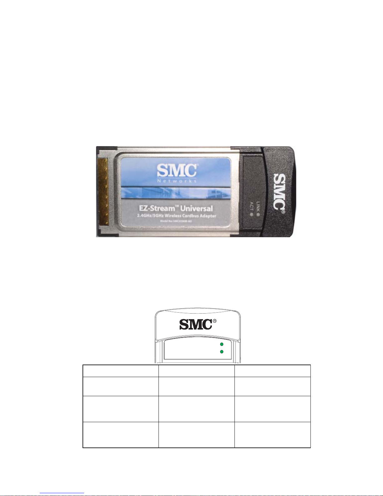
LEDs
The two status LED indicators of the SMC2336W-AG are
described in the following figure and table.
Link On (Green) Indicates a valid
Activity (ACT) Flashing Indicates that the
LINK
ACT
LED Status Description
connection.
Flashing Indicates the Adapter
is scanning for
available networks.
Adapter is transmitting
or receiving data.
5
Page 16
Hardware Installation
Hardware Installation
Warning: Network cards are sensitive to static electricity. To
protect the card, avoid touching its electrical
components, and touch the ground ofte n to eq u alize
the static charges, before handling the card.
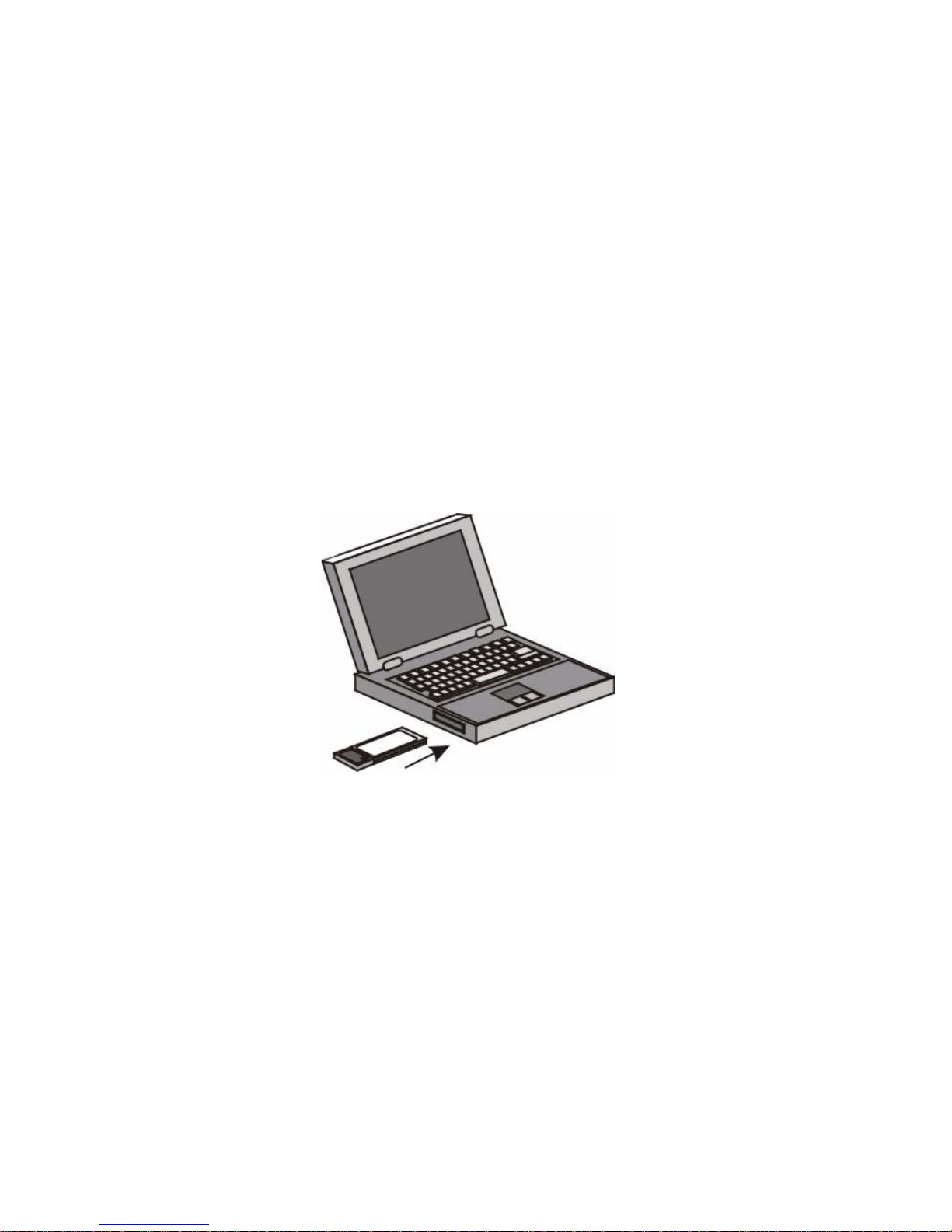
1. Find an av ailab le type II or type III CardBus slot in y our laptop.
2. With the Adapter’s 68-pin connector facing the CardBus slot,
and the “EZ-Stream” label f acing up, slid e the card completely
into the slot as shown below.
Note: The SMC2336W-AG Wireless CardBus Adapter allows
you to “hot swap” the card any time, even when your
notebook is powered on.
3. For Windo ws 98/Me/2000, CardBus specification is required.
Please check the documents for your Cardbus adapter driver
before installing the driver and utility software for the
SMC2336W-AG adapter.
6
Page 17

Driver and Utility Installation
Driver and Utility
Installation
The EZ Installation Wizard and Documentation CD that comes
with the package contains all the software drivers for the
SMC2336W-AG Adapter. Any new or updated drivers can be
downloaded from the SMC web site at www.smc.com. Also,
check the SMC web site for additional online support.
For Windows 98SE/Me/2000
You may find that the screen shots here do not e xactly match your
version of Windows. This is because these steps and screen
shots were created from Windows 2000. Steps for Windows
98SE and Windows Millennium Edition, are similar, but not
identical, to Windows 2000.
For driver and utility installation for Windows XP, see instructions
on page 12.
Note: For Windows 98SE users, installation processes may
require the use of your original copy of Windows OS.
Please have the Windows OS CD available BEFORE
proceeding with the installation.
1. Insert the EZ Installation Wizard CD into your CD-ROM drive
and click Install Driver/Utility. Then the Choose Setup
Language window will appear. Select the desired language
from the drop-down menu and click OK.
7
Page 18

Driver and Utility Installation
2. The InstallShield Wizard window then appears. There are 2
ways to install the driver and utility software. Click Easy to
continue with the Easy installation.
• If you select the Easy option, proceed directly to step 5.
• If you choose the Advanced option, proceed to step 3.
3. Select the operation mode for your adapter, and click Next.
8
Page 19

For Windows 98SE/Me/2000
Note: Infrastructure mode is a network connection involvin g one
or more access points. AdHoc mode is for connections
between different adapters, without any access points.
See “Network Configuration and Planning” o n page 31 for
details.
4. Enter the SSID and Channel of the network that your adapter
is connecting to, and click Next.
Note: See “Wireless Card Manager” on page 18 for more
information.
9
Page 20

Driver and Utility Installation
5. When this message appears, insert your SMC2336W-AG
adapter into your laptop.
6. After the software utility has been installed, click Finish to
continue the driver installation.
7. Windows OS will automatically detect the new hardware.
10
Page 21

For Windows 98SE/Me/2000
8. The Installation Wizard starts installing drivers into your hard
drive. You will see a screen as shown below. Though the
driver software is fully compatible with Windows 2000, it has
not yet been digitally signed by Microsoft. Click Yes to
continue the installation.
9. Select the country in which you are using the adapter, and
click OK to complete the installation.
Note: Make sure you choose the correct country, incorrect
selection will result in illegal operation.
11
Page 22

Driver and Utility Installation
When the installation is completed, the quick-launch icon will
appear on the desktop.
For Windows XP
1. Insert the EZ Installation Wizard CD into your CD-ROM drive
and click Install Driver/Utility. Then the Choose Setup
Language window will appear. Select the desired language
from the drop-down menu and click OK.
12
2. The InstallShield Wizard window then appears. There are 2
ways to install the driver and utility software. Click Next to
continue with the Easy installation.
• If you select the Easy option, proceed directly to step 5.
• If you choose the Advanced option, proceed to step 3.
Page 23

For Windows XP
3. Select the operation mode for your adapter, and click Next.
13
Page 24

Driver and Utility Installation
Note: Infrastructure mode is a network connection involvin g one
or more access points. AdHoc mode is for connections
between different adapters, without any access points.
See “Network Configuration and Planning” o n page 31 for
details.
4. Enter the SSID and Channel of the network that your adapter
is connecting to, and click Next.
Note: See “Wireless Card Manager” on page 18 for more
information.
14
Page 25

For Windows XP
5. When this message appears, insert your SMC2336W-AG
adapter into your laptop.
6. Windows OS will automatically detect the new hardware.
7. The Installation Wizard starts installing drivers into your hard
drive. You will see a screen as shown below. Though the
driver software is fully compatible with Windows XP, it has not
yet been Logo tested by Microsoft. Click Continue Anyway to
proceed with the installation.
15
Page 26

Driver and Utility Installation
8. Select the country in which you are using the adapter, and
click OK to complete the installation.
Note: Make sure you choose the correct country, incorrect
selection will result in illegal operation.
9. After the software driver and utility have been installed, click
Finish to complete the installation.
16
Page 27

For Windows XP
When the installation is completed, the SMC Wireless Card
Manager will start up for configuration. The quick-launch icon will
also appear on the desktop.
17
Page 28

Wireless Card Manager
Wireless Card Manager
To communicate with other wireless 802.11a, 11b, or 11g
devices, you need to configure the SMC2336W-AG Adapter first.
Double-click the icon on the desktop to launch the Wireless Card
Manager, or you can access it from the right bottom corner of the
Start menu.
Note that the screen shots were taken from Windows XP and will
not look exactly the same in all operating systems.
The Card Manager includes the following 5 tabs:
Configuration – Allows you to monitor network status and
configure wireless adapter parameters.
Link Information – Allows you to view network status.
IP Information – Displays TCP/IP data.
Site Survey – Scans/Shows all wireless devices within the
adapter’s signal range.
Version Information – Shows the driver and utility version
information.
At the bottom of the screen, there are three boxes that can be
selected:
• Radio On/Radio Off – This allows you to turn on/off the
transmission/reception of the adapter.
•Exit – This closes the Card Manager dialo gu e box.
18
Page 29

Configuration
Go to Configuration tab to set parameters f or the SMC233 6W -A G
adapter.
Configuration
Select Profile – You can specify a profile name for a specific
configuration of parameters.
New – To set up a new profile, click New.
Save – To save a new profile after configuring the settings, click
Save.
Delete – To delete a profile, select the profile from the drop do wn
menu in the Select Profile field, then click Delete.
19
Page 30

Wireless Card Manager
Common
SSID – Input an SSID for the wireless network to which you want
to connect. To roam among multiple access points with different
BSSIDs, set the SSID to ANY to allow connection to any access
point. (Default: ANY)
Operating Mode – Set the adapter’s operating mode to 802.11
AdHoc for a network enviroment that does not have an access
point, or to Infrastructure for connections with an access point.
Transmit Rate – Indicates the data transmission rate. Select an
appropriate transmission speed. Lower speeds will give better
range.
Channel – If you are setting up an ad hoc wireless network (see
“Network Topologies” on page 31), set the channel number to the
same radio channel as that used by the other wireless clients in
your group. However, if you are connecting to a network via an
access point, then the channel is automatically set by the access
point to the channel that it uses.
You only need to manually set the channel when the Operating
Mode is 802.11 AdHoc.
20
Page 31

Configuration
Note: The available channel settings are limited by local
regulations which determine the number of channels that
are available.
• U.S.: 1 ~ 11 channels
• Europe: 1 ~ 13 channels
• Japan: Channel 14
Power Save – allows you to enable the power saving mode for
reducing power loading.
Supported Wireless Type – Click on the checkbox for using
availabe operation types on your ne twork.
Security
Clicking on Security icon to enable the wireless security function
of the SMC2336W-AG. (Default: Security Off)
Authentication Type – To start using the encryption security on
the wireless network, choose Open or Shared from the list.
(Default: Open)
Set the Key Length to 152-bit, 128-bit or 64-bit for encryption
keys. (Default: 64 bit)
21
Page 32

Wireless Card Manager
The WEP (Wired Equivalent Priv acy) mechanism impleme nted in
the SMC2336W-AG Adapter is based on the RC4 encryption
algorithm. The encryption keys are provided to ensure data
confidentiality. WEP security protects your wireless LAN against
eavesdropping and unauthorized access by intruders. If WEP is
in use, all clients on the same network must use the same WEP
key settings in order to communicate with each other.
Use Passphrase – Check this bo x to auto-generate keys for
encryption. First, check this box, then enter a string of characters
into the space. Encryption keys will be generated automatically.
When Encryption is set to 128-bit, only one key will be generated.
If Encryption is set to 64-bit, 4 keys will be generated. Note that
you must use the same passphrase and Default key on all the
other clients in your network.
Note: A passphrase string can contain up to 32 alphanumeric
characters.
Key Type – Select ASCII or Hex.
Default Key – Choose the Key for encryption.
How to set up WEP
• 128-bit or 64-bit WEP
To set up the WEP function, take the following steps:
1. Select 128-bit or 64-bit in the Encryption field.
2. To automatically generate keys, check the Passphrase box,
and type in a string of characters in this field.
3. In the Default Key field, select one key as the default key that
you want to use for encryption.
4. Click Apply changes to allow the settings to take effect.
22
Page 33

Configuration
Or
1. Select 128-bit or 64-bit in the Encryption field.
2. In the Key type field, select ASCII or Hex.
3. In the Default Key field, select one key as the default key that
you want to use for encryption.
4. Manually type in a string of characters in the corresponding
Key number field that you selected in step 3.
5. Click Apply changes to allow the settings to take effect.
Note: When setting up WEP without using the Passphrase
function, if the Key Type is set to Hex, only Hexadecimal
characters (range: 0~9 an d A~F ) ca n be use d. When
encryption is set to 64-bit, a maximum of 10 Hex
characters can be entered in the Key field. When
encryption is set to 128-bit, a maximum of 26 Hex
characters can be used. If the Key Type is set to ASCII,
and encryption is set to 64-bit, then 5 ASCII characters
can be used in the Key field. For 128-bit en cr yp tion , 13
ASCII characters can be used.
• 152-bit WEP
If the 152 bit WEP is used, select the ASCII key type and choose
the Default K ey number. Then enter the key characters. 16 ASCII
characters can be used.
23
Page 34

Wireless Card Manager
• ASCII Per-User Key
1. Choose the Key Length.
2. Select the ASCII as the Ke y Type and the Per-User k ey as the
Default Key.
3. Type in a string of characters in the Per-User field.
4. Click Apply changes to allow the settings to take effect.
Advanced
RTS Threshold – Set the R TS (Request to Send) fr ame length. If
the packet size is smaller than the preset RTS threshold size, the
RTS/CTS mechanism will NOT be enabled. (Default: disabled)
24
Page 35

Configuration
Fragmentation Threshold – The Fragmentation Threshold can
be set between 256 and 2,346. If the packet size is smaller than
the preset Fragment size, the packet will not be segmented.
(Default: disabled)
Site Scan T ype – Use this option f or autom atically scanning valid
access points on the network. (Default: Active)
Preamble type – The access points and client card drivers have
a radio setting for RF Preamble. Enabling it can boost your
throughput. If you are not sure whether all the clients and access
point radios in your wireless network support the Short RF
preamble, then leave this setting to the default (Long).
QoS (Quality of Service) – Use QoS to specify a guaranteed
throughput level. (Default: disable)
Tx Po wer – Mo ve the slider up and do wn to increase or decrea se
the transmission power.
25
Page 36

Wireless Card Manager
Link information
The Link information screen displays information on the current
wireless network that you are connec te d to.
26
SSID – The service set identification for the wireless network that
the adapter is connected to.
Asssociated BSS ID – The MAC address of the access point to
which the adapter is connected in an infr astructure network. In an
ad hoc network, the BSS ID is a random number generated by
the first adapter that communicates with other clients in the
network. The BSS ID of the other clients will then be set to the
same value.
Channel – The channel used to connect with the wireless device.
Current Tx Rate – The data transmission rate.
Page 37

Current Rx Rate – The data receiving rate.
Encryption – Shows the security status of the connection.
Wireless Type – Shows the connection type.
Throughput
Rx Fragments – The number of received fragments.
Tx Fragments – The number of transmitted fragments.
Signal Strength – Shows the strength of the con nection between
the adapter and the access point.
IP Information
Configuration
This screen displays IP information for your notebook. Now that
you have configured your adapter to connect to a wireless
network, your adapter needs to obtain new network settings. By
releasing old IP settings and renewing them with settings from
the access point, you will also verify that you have configured
your adapter correctly. To release network settings click on
Release button, then click on Renew to get a new IP settings.
27
Page 38

Wireless Card Manager
IP Address – Internet address of the notebook.
IP Netmask – A mask used to determine what subnet an IP
address belongs to.
Gateway – The IP address of the network gateway.
Host Name – The notebook’s name on the network.
incoming/outgoing – Shows the traffic activity of the wireless
connection.
Site Survey
Site Survey scans and displays all wireless devices within range.
You can choose one of them to connect to by double-clicking on
an entry.
28
Page 39

Configuration
Network Type – This shows the operating mode of the listed
wireless devices.
SSID – Service Set ID. See “Configuration” on page 19for details.
Type – Shows the wireless network is operating in 802.11a, 11b,
or 11g.
WEP – The key icon indicates that WEP has been enabled.
Signal – This shows the signal strength from the adapter to the
listed access points.
Channel – The radio channel on which the access point
operates. See “Link information” on page 26 for details.
Scroll right to see more information of the Site browse screen.
29
Page 40

Wireless Card Manager
BSSID – Basic Service Set ID . See “Link information” on page 26
for details.
Version Information
This screen shows inf ormation on the current ver sion of the driver
and Card Manager. You can download the latest firmware from
the SMC web site at www.smc.com.
30
Page 41

Network Configuration and Planning
Network Configuration
and Planning
SMC’s EZ-Stream Wireless Solution supports a stand-alone
wireless network configuration, as well as an integrated
configuration with 10/100 Mbps Ethernet LANs.
The SMC2336W-AG can be configured as:
• Ad hoc - for small groups that only communicate with each
other, without access points
• Infrastructure - for wireless LANs
Network Topologies
Ad Hoc Wireless LAN
An ad hoc wireless LAN
consists of a group of
computers, each equipped
with one wireless adapter,
connected via radio signals
as an independent wireless
LAN. Computers in a
specific ad hoc wireless
LAN must therefore be
configured to the same
radio channel. An ad hoc
Ad Hoc Wireless LAN
Notebook with
Wireless USB Adapter
Notebook with
Wireless PC Card
PC with Wireless
PCI Adapter
wireless LAN can be used
in a SOHO or temporar y environme nt .
31
Page 42

Network Configuration and Planning
Infrastructure Wireless LANs
The SMC (802.11a/11b/11g) access points can also provide
wireless workstations with access to a wired LAN. An integrated
wired and wireless LAN is called an infrastructure configuration. A
Basic Service Set (BSS) consists of a group of wireless PC
users, and an access point that is directly connected to the wired
LAN. Each wireless PC in this BSS can talk to any computer in its
wireless group via a radio link, or access other computers or
network resources in the wired LAN infrastructure via the access
point.
The infrastructure configuration not only extends the accessibility
of wireless PCs to the wired LAN, but also extends the effective
wireless transmission range for wireless PCs by passing their
signal through one or more access points.
A wireless infrastructure can be used for access to a central
database, or f or connection betw een mobile workers , as sho wn in
the following figure.
Wired LAN Extension
to Wireless Adapters
File
Server
Desktop PC
Switch
Access Point
PC with Wireless
PC I Adapter
Notebook with Wireless
PC Card Adapter
32
Page 43

Setting the Communication Domain
Setting the Communication Domain
Stationary Wireless PCs
The Basic Service Set (BSS) is the communication domain for
each access point. For wireless PCs that do not need to support
roaming, set the domain identifier (SSID) for the wireless card to
the SSID of the access point you want to connect to. Check with
your administrator for the SSID of the access point you should
connect to.
Roaming Wireless PCs
A wireless infrastructure can also support roaming for mobile
workers. More than on e access point can be configured to crea te
an Extended Service Set (ESS). By placing the access points so
that a continuous coverage area is created, wireless users within
this ESS can roam freely. All wireless adapters and access points
within a specific ESS must be configured with the same SS ID
and to the same radio channel.
File
Server
Desktop PC
<ESS>
Switch
Access Point
PC with Wireless
PC I Adapter
Notebook with Wireless
PC Card Adapter
<BSS2>
Wireless Cell
Coverage Area
PC with Wireless
PCI Adapter
<BSS1>
Access Point
Notebooks with Wireless
PC Card Adapters
Seamless Roaming
33
Page 44

Network Configuration and Planning
Before setting up an ESS f or roaming, y ou need to choose a clear
radio channel and a suitable location for the access points for
optimum perf ormance. (Ref er to “Troubleshooting” on page 3 5 f or
detailed information on installation and usage)
34
Page 45

Troubleshooting
Check the following troubleshooting items bef ore contacting SMC
technical support.
Adapter Installation Problems
If your notebook cannot find the SMC2336W-AG Adapter or the
driver software does not install correctly, check the following:
• Make sure the adapter is securely seated in th e CardBus slot.
When you insert the wireless adapter into the notebook’ s slot,
Troubleshooting
your notebook shou ld make a beepin g sound, if the adapter is
properly inserted. Check for any hardwa re prob lems, such as
physical damage to the card’s connector.
• Try the card in another CardBus slot. If this also f ails, test y our
notebook with another wireless adapter that is known to
operate correctly.
• Make sure your notebook is using the latest BIOS.
• If there are other network adapters in the noteb ook, the y ma y
be causing conflicts. Remove all other adapters from the
notebook and test the wireless adapter separately.
• If it still does not work, take out the wireless adapter. Go to
“Control Panel” and delete the adapter from your network
configuration menu. Restart your laptop and reinstall the card
and the driver and utility.
35
Page 46

Troubleshooting
Network Connection Problems
If the Link LED on the SMC2336W-AG Adapter does not light, or
if you cannot access any network resources from the notebook,
check the following:
• Make sure the correct software driver is installed for your
operating system. If necessary, try reinstalling the driver.
• Make sure the notebook and other network devices are
receiving power.
• The access point you wa nt to connect to may be def ective. Try
using another access point.
• If you cannot access a Windows or NetWare service on the
network, check that you have enabled and configured the
service correctly. If you cannot connect to a particular server,
be sure that you have access rights and a valid ID and
password.
• If you cannot access the Internet, be sure y ou have configured
your system for TCP/IP.
If your wireless station cannot communicate with a computer in
the Ethernet LAN when configured for Infrastructure mode, check
the following:
• Make sure the acce ss point that the station is associated with
is powered on.
• If the connection still fails, chang e the access point and all the
clients within the BSS to another radio channel.
• For a station with roaming disab led, make sure the SSID is the
same as that used by the access point, or the same as that
used by the access points in the extended service set (ESS).
36
Page 47

Network Connection Problems
SMC Networks EZ-Stream Wireless Cardbus Adapter
Maximum Distance Table
Important Notice
Maximum distances posted below are actual tested distance
thresholds. However, there are many variables such as barrier
composition and construction, as well as local environmental
interfer ence that ma y impact your actual dista nces and cause you
to experience distance thresholds far lower than those posted
below. If you have any questions or comments regarding the
features or performance of this product, or if you would like
information regarding our full line of wireless products, you can
visit us at www.smc.com, or you can call us toll-free at
800.SMC.4YOU. SMC Networks stands behind every product
sold with a 30-day satisfaction guarantee and a limited-lifetime
warranty.
Environmental
Condition
Outdoors
Indoors
1
2
3
108
Mbps
25 m
(82
ft)
8 m
(26
ft)
802.11a Wireless Distance Table
Speed and Distance Ranges
72
Mbps
40 m
(131
ft)
20 m
(66
ft)
54
Mbps
85 m
(279
ft)
25 m
(82
ft)
48
Mbps
250
m
(820
ft)
35 m
(115
ft)
36
Mbps
310
m
(101
6 ft)
40 m
(131
ft)
24
Mbps
400
m
(131
1 ft)
45 m
(148
ft)
18
Mbps
445
m
(145
9 ft)
50 m
(164
ft)
12
Mbps9 Mbps6 Mbps
455
m
(149
2 ft)
55 m
(180
ft)
465
m
1525
ft
66 m
(216
ft)
510
m
1672
ft
70 m
(230
ft)
37
Page 48

Troubleshooting
802.11b Wireless Distance Table
Speed and Distance Range
Environmental
Condition
Outdoors
Indoors
1
2
3
Environmental
Condition
Outdoors
Indoors
1
2
3
802.11g Wireless Distance Table
Speed and Distance Range
54
Mbps
82 m
(269
ft)
20 m
(66 ft)
48
Mbps
100 m
(328
ft)
25 m
(82 ft)
11
Mbps
300 m
(984
ft)
60 m
(197
ft)
36
Mbps
300 m
(984
ft)
35 m
(115
ft)
5.5
Mbps2 Mbps1 Mbps
465 m
(1525
ft)
70 m
(230
ft)
24
Mbps
300 m
(1082
ft)
43 m
(141
ft)
500 m
(1639
ft)
83 m
(272
ft)
18
Mbps
350 m
(1148
ft)
50m
(164
ft)
12
Mbps9 Mbps6 Mbps
450 m
(1475
ft)
57 m
(187
ft)
515 m
(1689
ft)
85 m
(279
ft)
485 m
(1590
ft)
71 m
(233
ft)
495 m
(1623
ft)
80 m
(262
ft)
Notes: 1. The application of the 72Mbps turbo mode is subjected
to in-country regulations.
2. Outdoor Environment: A line-of-sight en vironmen t with
no interference or obstruction between the access
point and clients.
3. Indoor Environment: A typical office or home
environment with floor to ceiling obstructions between
the access point and clients.
38
Page 49

Specifications
General Specifications
Functional Criteria
Data Rate
802.11a:
Normal Mode: 6, 9, 12, 18, 24, 36, 48, 54 Mbps per channel
Turbo Mode: 12, 18, 24, 36, 48, 72, 108 Mbps per channel
802.11b: 1, 2, 5.5, 11 Mbps
802.11g: 1, 2, 5.5, 11, 6, 9, 11, 12, 18, 24, 36, 48, 54 Mbps
Specifications
Operating Range
802.11a: Up to 510m (1672 ft)
802.11b/g: Up to 515m (1689 ft)
Radio Signal
Signal Type
Orthogonal Frequency Division Multiplexing (OFDM)
Direct Sequence Spread Spectrum (DSSS)
Modulation Techniques
802.11a,g (OFDM): BPSK, QPSK, 16-QAM, 64-QAM
802.11b (DSSS): DBPSK, DQPSK, CCK
Channel Support
FCC: 1-11, ETSI: 1-13, TELEC: 1-14
RF Output Power
16 dBm
Physical Characteristics
Power Consumption
Transmission mode: 480mA
39
Page 50

Specifications
Receive mode: 380 mA
Dimensions
118.6 x 54.0 x 4.85 mm (4.67 x 2.13 x 0.19 in.)
Antenna
Built-in antenna
LED Indicators
Activity (ACT), Network Link (LINK)
Host Interface
32-bit Cardbus interface
Power Voltage
3.3 Volt + 5%
Standards Conformance
Wireless Standard: IEEE 802.11a, IEEE 802.11b,
IEEE 802.11g
Environmental
TemperatureOperating: 0 to 55 °C (32 to 122 °F)
Storage: -20 to 65 °C (32 to 158 °F)
Humidity: 5 to 95% (noncondensing)
Certification
CE Mark, EN50081-1, EN55022 Class B
EN50082-1, IEC 61000-4-2, IEC 60601-1 -2
FCC Part 15 Class B
UL1950/CSA22.2 No.950
IEC 60950
Software Drivers
Windows 98SE
Windows Me
Windows 2000
Windows XP
40
Page 51

General Specifications
Data Rate and Output Power
Note: For 802.11b, CH1, CH13, and CH14 output power >16
dBm
Standard Data Rate Output Power
802.11a 6 Mbps 16
9 Mbps 16
12 Mbps 16
18 Mbps 16
24 Mbps 16
36 Mbps 16
48 Mbps 16
(dBm)
54 Mbps 13
802.11b 1 Mbps 17
2 Mbps 17
5.5 Mbps 17
11 Mbps 17
802.11g 6 Mbps 16
9 Mbps 16
12 Mbps 16
18 Mbps 16
24 Mbps 15
36 Mbps 15
48 Mbps 13
54 Mbps 13
41
Page 52

Specifications
Typical Range and Receiver Sensitivity
Note: 802.11a,g: Frame (1000 Bytes PDUs) Packet Error Rate
<10%.
802.11b: Frame (1024 Bytes PDUs) Packet Error Rate
<8%
Standard Data Rate Modulation
802.11a 6 Mbps -85
9 Mbps -84
12 Mbps -83
Rate
Receiver
Sensitivity
(dBm)
18 Mbps -81
24 Mbps -78
36 Mbps -74
48 Mbps -69
54 Mbps -65
802.11b 1 Mbps -88
2 Mbps -86
5.5 Mbps -84
11 Mbps -82
802.11g 6 Mbps -88
9 Mbps -87
12 Mbps -84
18 Mbps -82
24 Mbps -79
36 Mbps -75
48 Mbps -68
42
54 Mbps -68
Page 53

Terminology
Terminology
Access Point – An internetworking device that seamlessly
connects wired and wireless networks.
Ad Hoc – An ad hoc wireless LAN is a group of laptops or
computers, each with LAN adapters, connected as an
independent wireless network.
Base Station – In mobile telecommunications, a base station is
the central radio transmitter/receiver that maintains
communications with the mobile radiotelephone sets within its
range. In cellular and personal communications applications,
each cell or micro-cell has its o wn base station; each ba se station
in turn is interconnected with other cells’ bases.
BSS – BSS stands for “Basic Service Set.” It is an Access Point
and all the LAN PCs that are associated with it.
ESS – ESS (ESS-ID, SSID) stands for “Extended Service Set.”
More than one BSS is configured to become an Extended
Service Set. LAN mobile users can roam between different BSSs
in an ESS (ESS-ID, SSID).
Ethernet – A standard for comp uter networks. Eth ernet networks
are connected by special cables and hubs or switches, and it
operates at 10 Mbps.
Fragmentation Threshold – In the 802.11 Standard, the MAC
Layer may fragment and reassemble directed MSDUs or
MMPDUs. The fragmentation and defragmentation mechanisms
allow for fragment re-transmission.
Infrastructure – An integrated wireless and wired LAN is called
an Infrastructure network.
43
Page 54

Terminology
Roaming – A function that allows you to move through a
particular domain without losing network connectivity.
RTS Threshold – Transmitters contending for the medium may
not be aware of each other. The RTS/CTS mechanism can solve
this “Hidden Node Problem.” If the packet size is smaller than the
preset RTS Threshold size , the RTS/CTS mechanism will NO T be
enabled.
WEP – “Wired Equivalent Privacy” is based on th e use of 64-bit or
128-bit keys and the popular RC4 encryption algorithm for
enhanced network security.
44
Page 55

FOR TECHNICAL SUPPORT, CALL:
From U.S.A. and Canada (24 hours a day, 7 days a week)
(800) SMC-4-YOU; Phn: (949) 679-8000;
Fax: (949) 679-1481
From Euro pe : Contact details can be found on
www.smc-europe.com or www.smc.com
INTERNET
E-mail addresses:
techsupport@smc.com
european.techsupport@smc-europe.com
Driver updates:
http://www.smc.com/
index.cfm?action=tech_support_drivers_downloads
World Wide Web:
http://www.smc.com
http://www.smc-europe.com
FOR LITERATURE OR ADVERTISING RESPONSE, CALL:
U.S.A. and Canada: (800) SMC-4-YOU; Fax (949) 679-1481
Spain: 34-91-352-00-40; Fax 34-93-477-3774
UK: 44 (0) 1932 866553; Fax 44 (0) 118 974 8701
France: 33 (0) 41 38 32 32; Fax 33 (0) 41 38 01 58
Italy: 39 (0) 335 5708602; Fax 39 02 739 14 17
Benelux: 31 33 455 72 88; Fax 31 33 455 73 30
Central Europe: 49 (0) 89 92861-0; Fax 49 (0) 89 92861-230
Nordic: 46 (0) 868 70700; Fax 46 (0) 887 62 62
Eastern Europe: 34 -93-477-4920; Fax 34 93 477 3774
Sub Saharian Africa: 216-712-36616; Fax 216-71751415
North West Africa: 34 93 477 4920; Fax 34 93 477 3774
CIS: 7 (095) 7893573; Fax 7 (095) 789 35 73
PRC: 86-10-6235-4958; Fax 86-10-6235-4962
Taiwan: 886-2-8797-8006; Fax 886-2-8797-6288
Asia Pacific: (65) 238 6556; Fax (65) 238 6466
Korea: 82-2-553-0860; Fax 82-2-553-7202
Japan: 81-45-224-2332 ; Fax 81-45-224-2331
Australia: 61-2-8875-7887; Fax 61-2-8875-7777
India: 91-22-8204437 ; Fax 91-22-8204443
If you are looking for further contact information, please visit
www.smc.com, www.smc-europe.com, or www.smc-asia.com.
38 Tesla
Irvine, CA 92618
Phone: (949) 679-8000
Model Number: SMC2336W-AG
Revision number:
E102003-R01 WW F1.0
 Loading...