

Page 1

EZConnect USB/Ethernet Cable Modem
• DOCSIS v1.0 Certified
• USB Port for Fast Easy Installation on
Windows 98/2000/Me and XP
• Up to 38 Mbps downstream, 10 Mbps
upstream Throughput
• BPI provides encrypted secure data
transmission across the cable network
Installation Guide
SMC8002CM
Page 2

CONTENTS
CONTENTS .................................................................................................2
INTRODUCTION.......................................................................................4
ACRONYMS................................................................................................4
OVERVIEW.................................................................................................5
CABLE MODEM BOX CONTENTS ................................ ....................................5
EXTERNAL INDICAT ORS AND INTERFACES.......................................................5
BACK PANEL INTERFACES:............................................................................. 5
FRONT PANEL LED DESCRIPTIONS ................................................................ 6
FRONT PANEL OF THE CABLE MODEM............................................................ 6
FEATURES AND SPECIFICATIONS..................................................................... 7
INSTALLATION PROCEDURE.............................................................9
PHYSICAL PLACEMENT ................................................................................10
CONNECTING TO THE CABLE SYSTEM..........................................................10
VERIFYING POWER REQUIREMENTS............................................................. 11
CONNECTING POWER...................................................................................12
CONNECTING A PC TO THE CABLE MODEM WITH AN ETHERNET CABLE .......12
CONNECTING A PC TO THE CABLE MODEM WITH A USB CABLE...................13
CABLE MODEM POWER-ON AND INITIALIZATION SEQUENCE........................17
VERIFYING INSTALLATION................................ ............................18
INTERNET C ONNECTION ..............................................................................18
TROUBLESHOOTING..........................................................................18
FAQ .............................................................................................................19
EVENT LOG MESSAGE .......................................................................21
2
SMC8002CM Installation Guide
Page 3

DOWNSTREAM ACQUISITION FAILED............................................................21
FAILED TO OBTAIN UPSTREAM PARAMETERS ................................ ...............22
RANGING FAILED: RNG-REQ RANGING REQUEST.......................................22
RANGING FAILED: RNG-RSP RANGING R ESPONSE ......................................23
REGISTRATION FAILED: REG-REQ REGISTRATION REQUEST......................23
REGISTRATION FAILED: REG-RSP REGISTRATION RESPONSE .....................24
DHCP AND TOD FAILED BEFORE REGISTRATION.......................................24
TOD FAILED.............................................................................................25
FTP FAILED..............................................................................................25
1.1 25
SW U PGRADE ..............................................................................................25
WEB USER INTERFACE .....................................................................26
WEB USER INTERFACE HOME PAGE.............................................................27
CABLE MODEM CONFIGURATION.................................................................28
CABLE MODEM STATUS ................................ ...............................................28
OPERATION CONFIGURATION.......................................................................31
INTERFACE RATE................................ .........................................................31
EVENT LOG .................................................................................................32
SET SEARCH FREQUENCY PARAMETERS.......................................................32
SET E THERNET TYPE...................................................................................33
CHANGE USERNAME AND PASSWORD ............................................................33
SMC8002CM Installation Guide
3
Page 4

INTRODUCTION
The EZConnect USB/ETH cable modem is based on the Broadcom 3350 chipset and is
DOCSIS 1.0 certified. This cable modem provides high speed access to the Internet
through a coaxial cable with a cable service provider. It also utilizes the cable television
network to transmit high-speed data to your PC.
This user’s guide describes how to set up and use the EZConnect USB/ETH cable
modem. Before installing the cable modem, you should read this installation guide
thoroughly to ensure proper operation.
ACRONYMS
CM Cable Modem. A device that converts the data collected from the Internet
and sent to a home through a cable TV company's line into data that a PC
can understand. The modem lets you to connect to th e Internet without a
telephone line. Cable modems can ferry data up to 38 mbps downstream
and from 200 kbps to 10 mbps upstream. The transmission rate will depend
on your service provider.
CMTS Cable Modem Termination System. A data-switching system that routes
data between cable modem users and the Internet.
DOCSIS Data Over Cable Service Interface Specifications. A cable TV industry
standard set by CableLabs for cable modems. This standard ensures that
certified modems can be used by all U.S. cable systems that market
broadband connections.
RF Radio Frequency.
TCP/IP Transmission Control Protocol/Internet Protocol. The primary protocol
used on the Internet, TCP/IP supports data communication across
interconnected networks and applications. All PCs connected to the
Internet use TCP/IP to communicate with each other.
USB Universal Serial Bus. A port that connects up to 127 peripheral devices —
including modems, printers, scanners, keyboards and PC mice — to a
single PC in a networking arrangement.
4
SMC8002CM Installation Guide
Page 5
Cable Modem Box Contents
This package consists of the following components:
Ø One SMC8002CM cable modem unit
Ø One AC to DC power adapter
Ø One straight-through Ethernet cable (1.8m)
Ø One USB cable (1.5m)
Ø One 3.5” diskette containing the Windows 98/Me/2000 USB drivers
Ø This installation guide
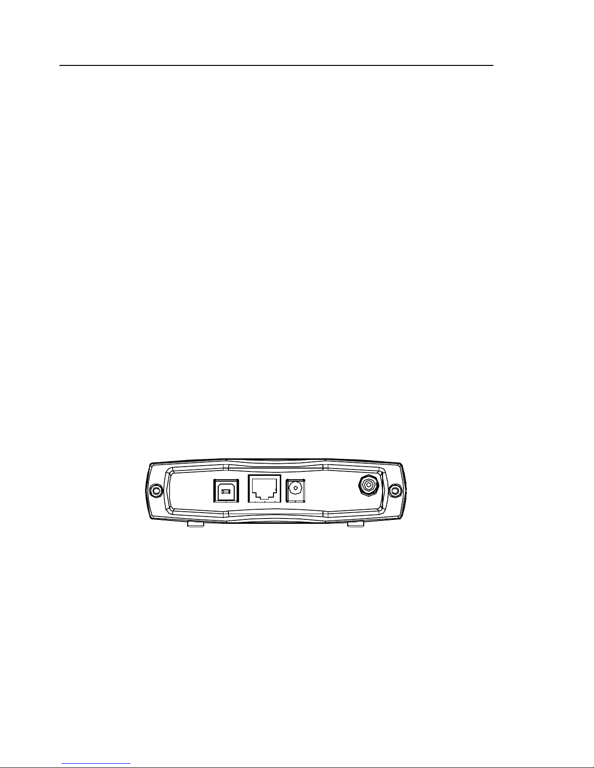
External Indicators and Interfaces
Back Panel Interfaces:
Ø USB: Universal Serial Bus port
Ø ENET: Ethernet port
OVERVIEW
Ø Power: 10Vdc Power port
Ø RF: CATV F-connector port
USB
ENET
PWR
RF
Back Panel of the Cable Modem
SMC8002CM Installation Guide
5
Page 6
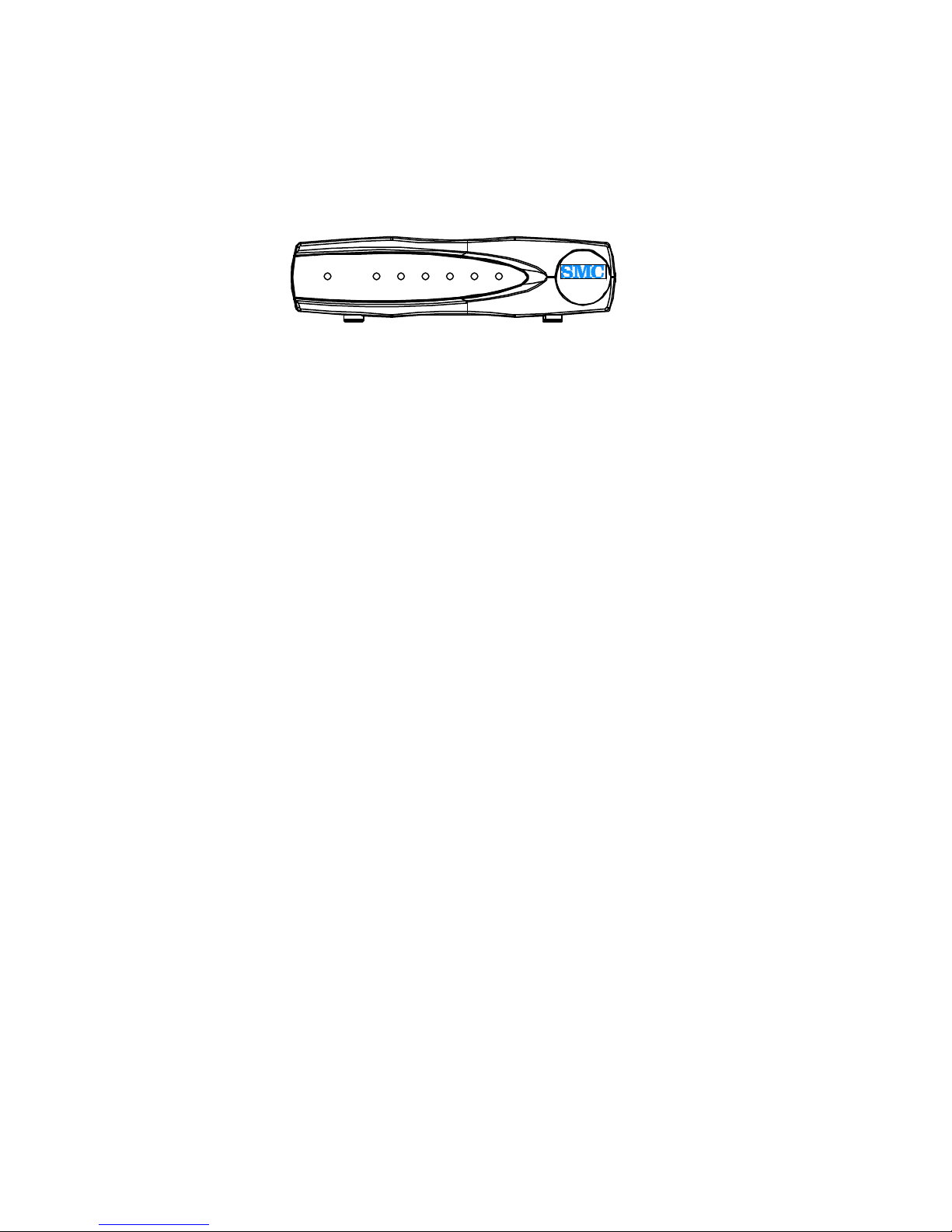
Front Panel LED Descriptions
POWER USB
SYNCENET SEND RECV. READY
SMC8002CM
Front Panel of the Cable Modem
Ø POWER: Indicates that the cable modem is ready.
Ø USB: L ights up when the cable modem and PC are linked by the USB cable.
Ø ENET: Lights up when the cable modem and PC are linked by the Ethernet
cable.
Ø SEND: Indicates that data is transmitting from the cable modem to the cable
modem system.
Ø RECV: Indicates that data is being received from CMTS to the cable modem.
Ø S YNC: Indicates the connection status between the cable modem and the
CM system.
Ø READY: Indicates that the cable modem has finished the ranging/
registration process and is ready to send/receive data.
6
SMC8002CM Installation Guide
Page 7

Features and Specifications
Speed: Supports two-way cable transmission rates of up to 38Mbps downstream
and 10Mbps upstream. The transmission rate will depend on your service provider,
and your connection (Ethernet or USB) for cable modem data transfer.
Convenience: Plug and play connectivity to your PC. Choose USB or traditional
Ethernet for connection to your computer.
Security: Supports DOCSIS Baseline Privacy to secure data integrity for safe
information exchange.
System Compliance: The SMC8002CM cable modem is compliant with Microsoft
WHQL device driver requirements.
Compatibility: The SMC8002CM cable modem is DOCSIS certified which
ensures interoperability with all DOCSIS configured systems.
DOCSIS1.1 Upgrade: The SMC8002CM cable modem is software upgradeable to
DOCSIS 1.1 by service providers.
SMC8002CM Installation Guide
7
Page 8

e and Cable, Security MIB support
Product Specifications
ITEM DOWNSTREAM (RECEIVER) UPSTREAM (TRANSMITTER)
Frequency Range 88MHz ~ 860MHz 5MHz ~ 42MHz
Channel Bandwidth DOCSIS: 6MHz 200K, 400K, 800K, 1.6M, 3.2MHz
Modulation 64QAM/256QAM QPSK/16QAM
Symbol Rate 5.057/5.361 Msymbols/sec 160, 320, 640, 1280, 2560 Ksymbols/sec
Data Rate 30Mbits/sec (64QAM)
43Mbits/sec (256QAM)
Input Output Power -15dBmV ~ +15dBmV +8dBmV ~ +58dBmV (QPSK)
Carrier To Noise Ratio @BER<10
RF Cable Inter face
PC Host Interface Ethernet or USB cable
Power Dissipation < 6 Watts
MAC, LLC/SNAP, IP and CPE Filter
ARP, ICMP, IP, TCP/UDP, IGMPv2 RFC826, RFC792, RFC791, RFC768/793
DHCP, TFTP, ToD client RFC2131/2132, RFC1350, RFC867 Applications for Provisioning usage
SNMP v2c RFC1905 SNMP Protocol
MIBs Support RFC1213, RFC2011, RFC2012, RFC2013
Syslog client Send event to syslog server
- 8
64QAM: 23.5dB, 256QAM: 30dB
75Ω F-type female connector
RFC2236
RFC2669, RFC2670, RFC2233, RFC1907,
RFC1493, draft -ietf-ipcdn -mcns-bpi-mib-01
0.32 ~ 5.12Mbs (QPSK)
0.64 ~ 10.24Mbs (16QAM)
+8dBmV ~ +55dBmV (16QAM)
DOCSIS -RFI
Internet Protocol Stack
MIB-2, Interfac
Hardware Specifications
Description Specification
Dimensions (H x W x D) 32.8 x 132 x 191.6 mm
AC Power (Input) Linear: AC 100 ~ 120 Volt (50 ~ 60 Hz)
or AC 220 ~ 240 Volt (50 ~ 60 Hz)
Switching: AC 100 ~ 240 Volt (Optional)
Power Consumption 8 to 10W
Temperature
Operating: 32°F to 104°F (0°C to 40°C)
Non-operating: 14°F to 158°F (-10°C to 70°C)
Humidity 5 to 95% non-condensing
Cable Interface Type F coaxial connector
LAN Interface Ethernet 10/100BaseT (RJ-45)
USB Interface USB Series B Connector
Regulatory Compliance FCC part 15, UL/CSA C22.2, CB, VCCI
8
SMC8002CM Installation Guide
Page 9

INSTALLATION PROCEDURE
The installation procedure is separated into five steps. Please take note of them before
proceeding with the installation. The installation checklist below will help you verify
each process.
Installation Check List
Item Task Checked off
1 Ensure the selected location is free of dust and meets all the
following requirements:
l Near the cable drop connection and power source.
l Install cable modem on a stable and flat surface.
Cables can reach all devices that need to be connected.
Ensure the bottom, sides, and rear of the cable modem
are clear of obstructions.
2 Check your PC environment:
l Verify PC to be connected to the cable modem has an
Ethernet Network Interface Card (NIC) with TCP/IP
networking enabled or a USB port is available.
l The cable modem does not support the USB and
Ethernet Port at the same time. Please choose one
connection type.
l The cable modem supports Ethernet NIC in all
Microsoft Windows operation systems.
l The cable modem supports USB in Microsoft
Windows 98, Windows 2000, or Windows Me.
3 Connect the cable modem’s F-connector to the cable TV
coaxial drop cable. (If you also subscribe to cable TV
services, install a cable splitter/directional coupler when
applicable.)
4 Attach the end of the power adapter cord into the cable
modem’s power connector and connect the other end to the
power plug. Plug the cable modem’s power adapter into the
wall outlet. Check if the cable modem’s power LED is on
and initialized.
5 Power on all other devices: PCs, Ethernet hub and all other
equipment when applicable.
SMC8002CM Installation Guide
9
Page 10

Physical Placement
Place the cable modem on a stable, flat surface such as a desktop, close to the CATV
cable drop connection and all devices to be connected. The surrounding areas of the
cable modem must remain unobstructed to ensure adequate airflow and to prevent the
unit from overheating.
Caution: Do not place the cable modem on an uneven or soft surface.
Connecting to the Cable System
Ø Verify that the cable modem is not connect ed to the power source. It will generate
installation difficulty if you power on the cable modem before connect RF coaxial
cable.
Ø Locate the RF coaxial cable from the CATV wall outlet.
Ø Install a cable splitter/directional coupler if it is needed to separate signals for TV
and PC usage.
Ø Connect the RF coaxial cable to the cable modem’s F-connector. Hand-tighten the
connector, making sure it is finger-tight.
Caution: Do not over-tighten the connector because doing so can break off the
connector.
Ø Make sure all other coaxial cable connectors and all intermediate splitters,
couplers, or ground blocks are securely tightened from the distribution tap to the
cable modem.
Note: Loose connectors inside the building or residence can cause intermittent
cable modem operation.
Caution: To ensure compliance with FCC limits, connection to the cable system
must be made with a high-quality, shielded cable. If the quality or general
condition of the coaxial cable is in question, it is recommended that you replace
the coaxial cable.
10
SMC8002CM Installation Guide
Page 11

Verifying Power Requirements
The cable modem will only accept 10Vdc, 1.2A power. An external AC-to-DC power
adapter must be used to make the cable modem work properly. Only the power
adapter accompanying this cable modem should be use d. Use of any other adapter
will void the product warranty.
We recommend that you follow these precautions:
Ø Verify the power adapter’s power plug is the same as that of your local power
outlet. If not, do not use it and ask your service provider for a replacement.
Ø If you are plugging the cable modem into an Uninterruptible Power Supply (UPS),
verify that the total power and current requirements used by all devices plugged
into the UPS are within the maximum limits of the UPS.
Ø Install proper grounding to avoid damage from lightning and power surges. If
using a North American (NEMA 5-15P) plug, you must plug the unit into a
three-lead receptacle to ensure proper grounding.
Warning: Never remove the ground conductor or operate the equipment in the
absence of a suitably installed ground conductor. Contact the appropriate
electrical inspection authority or an electrician if you are uncertain that suitable
grounding is available.
Ø Ensure that a proper fuse or circuit breaker is used on the phase conductors (all
current-carrying conductors providing power to the device).
Ø Do not work on the system, connecting or disconnecting any cables (Ethernet,
cable, or power) during periods of lightning activity. The possibility of serious
physical injury exists if lightning should strike and travel through those cables.
SMC8002CM Installation Guide
11
Page 12

Connecting Power
Ø Locate the power receptacle at the rear of the cable modem.
Ø Plug the AC power supply cord into the power connector at the rear of cable
modem.
Ø Connect the AC power cord to the power adapter.
Ø Plug the 3-prong end of the power cord into a standard electrical power outlet at
the site. The POWER LED on the front of the unit indicates that the power is being
supplied to the unit when it is connected and operational. The cable modem is
meant to be left powered on at all times, and therefore, has no power switch.
Ø Turn on the power for all other equipment, and wait for the devices to complete
their startup processes.
Warning: Never remove the ground conductor or operate the equipment in the
absence of a suitably installed ground conductor. Contact the appropriate electrical
inspection authority or an electrician if you are uncertain that suitable grounding is
available.
Connecting a PC to the Cable Modem with an Ethernet Cable
*** Please note that you can use either Ethernet or USB at one time, but not both simultaneously. ***
Ø Use the straight-through Ethernet cable to connect the cable modem.
Ø Connect one end of the Ethernet cable to the cable modem's Ethernet port at the
rear of the unit.
Ø Press the cable end firmly into the cable modem’s Ethernet receptacle and connect
the other end to your PC.
12
SMC8002CM Installation Guide
Page 13

Connecting a PC to the Cable Modem with a USB Cable
*** Please note that you can use either Ethernet or USB at one time, but not both simultaneously.***
Ø Locate the USB cable and connect one end of the USB cable to the cable modem's
USB port.
Ø Connect the other end of the USB cable to your computers USB port .
Ø You will see the dialog box below display on your PC .
Ø Click “Next”.
SMC8002CM Installation Guide
13
Page 14

Ø Select ‘Search for the best driver for your device.’
Ø Click “Next”.
Ø Insert the SMC8002CM driver disk into your floppy drive
Ø Select “Floppy disk drive”
Ø Click “Next”.
14
SMC8002CM Installation Guide
Page 15

Ø Select “SMC USB Cable Modem ”.
Ø Click “Next”.
Ø Windows is now ready to install the driver for the SMC USB Cable Modem.
Ø Click “Next”.
SMC8002CM Installation Guide
15
Page 16

Ø Place your Windows installation CD in the CD-ROM drive
Ø Click “OK”.
Ø When the Installation completes.
Ø Click “Finish”.
16
SMC8002CM Installation Guide
Page 17

Cable Modem Power-On and Initialization Sequence
When the cable modem is connected and powered on, it executes automatic
self-diagnostic and installation procedures. You can see the status from the LED
indicators on the front panel of the cable modem.
LED light off: O; LED light on: @; LED blinking: B; Don’t Care: X
STATUS POWER USB ENET SEND RECV SYNC READY
Initialization Sequence
Power ON @ @ X O @ @ @
Hardware Testing @ B X B B B B
Search Downstream
Channel
Downstream Locked @ X X X X @ O
Search Upstream Channel @ X X B X @ O
Ranging OK and
Registration Success
Data Transmission (use Ethernet cable)
Send Data @ O B B X @ @
Receive Data @ O B X B @ @
@ X X X B O O
@ X X X X @ @
Data Transmission (use USB cable)
Send Data @ @ X B X @ @
Receive Data @ @ X X B @ @
Ø If all LEDs appear normal, proceed to the "Verifying Installation" section to test
the cable modem and its connection to each part of the network. If any problem
occurs, proceed to “Troubleshooting” to solve the problem.
Ø After verifying operation, remember to keep the cable modem under the
recommended temperature requirement of 32° to 104° F (0° to 40° C). Keep the
area around the cable modem free from dust.
SMC8002CM Installation Guide
17
Page 18

VERIFYING INSTALLATION
Internet Connection
Use the following procedure to verify the Internet connectivity between the PC and
the cable modem. (Please note the Internet connectivity procedure stated in this
section may vary and it is subject to your Internet Services Provider. Kindly consult
your ISP if you have any question about your Internet connectivity.)
Ø Start the Internet browser program installed in the PC connected to the cable
modem.
Ø Enter a URL of your choice in your web browser. If the URL is not known, use
http://192.168.100.1 or browse your local ISP web server to connect to a web site.
Ø If the Ethernet cable is used, watch the appropriate LED on the front of the cable
modem blink as data is transferred. If the selected web page comes up in the
Internet browser screen, the network connection is successfully established and
Ethernet or USB is operational.
TROUBLESHOOTING
Installation problems with the SMc8002CM cable modem are commonly due to the
cable system and its topography. The LEDs on the front panel of the cable modem reveal
operational status and help you determine problem areas. See Section 2.2.2 for the
layout and description of the LEDs on the unit’s front panel.
18
SMC8002CM Installation Guide
Page 19

Table 5.1
LED Status
ENET
OFF
Possible Problem Suggested Action
PC/device not powered on. Verify the PC/device is powered
Or
USB
Bad connection. Reseat the Ethernet cable at both
Incorrect cable between the
cable modem and the PC.
Cable failed Replace the cable
Faulty Ethernet card or
USB port.
SYNC OFF
Cable modem searching for
a downstream signal;
RF levels wrong.
Cable is out. Check if the cable TV is
READY OFF
Cable modem is locked to a
DOCSIS downstream
signal.
on.
ends.
Replace the cable.
Replace the Ethernet card or fix
the USB port.
Consult your service provider.
working if you also subscribe to
broadcast TV services.
Wait until the cable modem
completes initialization.
Cable modem cannot
complete initialization.
Check with your service
provider.
Q: None of the LEDs are on when I power on the cable modem.
• Check the connection between the power adapter and the cable modem. If the
error still exists, you may have a hardware problem. Please contact your local
service provider.
SMC8002CM Installation Guide
FAQ
19
Page 20

Q: I cannot access Internet services.
• Check all connections. Make sure the cable line is securely connected to the
cable jack at the back of the cable modem. Verify that the Ethernet cable is
plugged into both the cable modem and the network interface card in your PC.
If your cable modem is properly connected, the “POWER”, “READY” and
“CABLE” indicator lights on the front of the cable modem should all be solid
green.
• Reset the power of your cable modem by removing the power adapter from its
outlet and then plugging it back into the outlet. Then try reconnecting to your
Broadband service provider. Refer to “Cable Modem Power-On and
Initialization Sequence” in section 4.7.
• The network interface card or USB interface in your PC may be
malfunctioning. This will prevent your PC from communicating with the
cable modem. Refer to your network interface documentation for
troubleshooting information.
Q: All of the LEDs on the front of my cable modem look right, but I still
cannot access Internet services.
Ÿ If the “POWER”, “READY” and “CABLE” LEDs are on, your cable modem is
operating properly. Try shutting down and powering off your PC and then turning it
on. This will allow your PC to re-establish communication with your cable
company’s syste m.
Ÿ You may not have installed TCP/IP properly or the TCP/IP parameters provided by
your cable company may not be correct for your PC. Please contact your local
service provider for assistance.
Q: USB interface is not working properly.
l Ensure your PC is using Windows 98, Windows Me, or Windows 2000. Windows
95 and Windows NT do not support networking function through the USB interface.
l Ensure the USB installation process and results are correct.
l Ensure there is a good connection between the PC and the cable modem.
Malfunction or bad quality of the USB cable can cause link failure.
20
SMC8002CM Installation Guide
Page 21

EVENT LOG MESSAGE
Event log message can be divided into the items listed below. Detailed information can
be found in each section.
• Downstream Acquisition Failed
• Failed to Obtain Upstream Parameters
• Ranging Failed : RNG-REQ Ranging Request
• Ranging Failed : RNG-RSP Ranging Response
• Registration Failed : REG-REQ Registration Request
• Registration Failed :REG-RSP Registration Response
• DHCP and TOD FAILED before registration
• TOD FAILED
• TFTP FAILED
• SW Upgrade
Downstream Acquisition Failed
ID Text
0 T00.0 SYNC Timing Synchronization
1 T01.0 Failed to acquire QAM/QPSK
symbol timing. Error stats? Retry #'s?
2 T02.0 Failed to acquire FEC framing.
Error stats? Retry #'s? # of bad frames?
3 T02.1 Acquired FEC framing. Failed to
acquire MPEG2 Sync. Retry #'s
4 T03.0 Failed to acquire MAC framing.
Error stats? Retry #'s? # of bad frames?
5 T04.0 Failed to Receive MAC SYNC
frame withi n time-out period.
6 T05.0 Loss of Sync. (Missed 5 in a row,
after having SYNC'd at one time)
SMC8002CM Installation Guide
21
Page 22

Failed to Obtain Upstream Parameters
ID Text
7 U00.0 UCD Upstream Channel Descriptor
8 U01.0 No UCD's Received. Time-out
9 U02.0 UCD invalid or channel unusable
10 U03.0 UCD valid, BUT no SYNC received. TIMED OUT
11 U04.0 UCD, & SYNC valid, NO MAPS for THIS Channel
12 U05.0 UCD received with invalid or out of order Configuration Change Count
13 U06.0 US Channel wide parameters not set before Burst Descriptors
14 M00.0 MAP Upstream Bandwidth allocation
15 M01.0 A transmit opportunity was missed
because the MAP arrived too late
Ranging Failed: RNG -REQ Ranging Request
ID Text
16 R00.0 RNG-REQ Ranging Request
17 R01.0 NO Maintenance Broadcasts for
Ranging opportunities Received T2 time-out
18 R04.0 Received Response to Broadcast Maintenance Request, But no Unicast.
Maintenance opportunities received. T4 timeout
19 Undefine
20 R101.0 No Ranging Requests received from POLLED CM (CMTS generated
polls)
21 R102.0 Retries exhausted for polled CM (report MAC address). After 16
R101.0 errors
22 R103.0 Unable to Successfully Range CM (report MAC address) Retries
Exhausted
23 Undefine
24 R104.0 Failed to receive Periodic RNG-REQ from modem (SID X),
timing-out SID
22
SMC8002CM Installation Guide
Page 23

Ranging Failed: RNG-RSP Ranging Response
• ID Text
25 R00.0 RNG-RSP Ranging Response
26 R02.0 No Ranging Response received, T3 timeout
27 R03.0 Ranging Request Retries exhausted
28 R05.0 Started Unicast Maintenance Ranging no Response received. T3
time-out
29 R06.0 Unicast Maintenance Ranging attempted. No Response. Retries
exhausted.
30 R07.0 Unicast Ranging Received Abort Response. Re-initializing
MAC..SP-RFI-I05-991105 Data-Over-Cable Service Interface Specifications
Registration Failed: REG-REQ Registration Request
• ID Text
31 I00.0 REG-REQ Registration Request
32 I04.0 Service not available. Reason: Other
33 I04.1 Service not available. Reason: Unrecognized configuration setting 34
I04.2 Service not available. Reason: Temporarily unavailable
35 I04.3 Service not available. Reason: Permanent
36 I101.0 Invalid MAC header
37 I102.0 Invalid SID, not in use
38 I103.0 Required TLV's out of order
39 I104.0 Required TLV's not present
40 I105.0 Down Stream Frequency format invalid
41 I105.1 Down Stream Frequency not in use
42 I105.2 Down Stream Frequency invalid, not a multiple of 62500Hz
43 I106.0 Up Stream Channel invalid, unassigned
44 I106.1 Up Stream Channel Change followed with (RE-)Registration REQ
45 I107.0 Up Stream Channel overloaded
46 I108.0 Network Access configuration has invalid parameter
47 I109.0 Class of Service configuration is invalid
48 I110.0 Class of Service ID unsupported
49 I111.0 Class of Service ID invalid or out of range
50 I112.0 Max Down Stream Bit Rate configuration is invalid format
51 I112.1 Max Down Stream Bit Rate configuration setting is unsupported
52 I113.0 Max Up Stream Bit Rate configuration setting invalid format
• ID Text
53 I113.1 Max Up Stream Bit Rate configuration setting unsupported
SMC8002CM Installation Guide
23
Page 24

54 I114.0 Up Stream Priority configuration invalid format
55 I114.1 Up Stream Priority configuration setting out of range
56 I115.0 Guaranteed Min Up Stream Channel Bit Rate configuration setting
invalid format
57 115.1 Guaranteed Min Up Stream Channel Bit Rate configuration setting
exceeds Max Up Stream Bit Rate
58 I115.2 Guaranteed Min Up Stream Channel Bit Rate configuration setting
out of range
59 I116.0 Max Up Stream Channel Transmit Burst configuration setting
invalid
60 I116.1 Max Up Stream Channel Transmit Burst configuration setting out of
range
61 I117.0 Modem Capabilities configuration setting invalid format
62 I117.1 Modem Capabilities configuration setting
Registration Failed: REG-RSP Registration Response
ID Text
63 I00.0 REG-RSP Registration Response
64 I01.0 Registration RSP invalid format or not recognized
65 I02.0 Registration RSP not received
66 I03.0 Registration RSP with bad SID
67 C00.0 UCC-REQ Upstream Channel Change Request
68 C01.0 UCC-REQ received with invalid or out of range US channel ID
69 C02.0 UCC-REQ received unable to send UCC -RSP, no TX opportunity
format
70 C100.0 UCC-RSP Upstream Channel Change Response
71 C101.0 UCC-RSP not received on previous channel ID
72 C102.0 UCC-RSP received with invalid channel ID Radio Frequency
Interface Specification SP-RFI-I05-991105
73 C103.0 UCC-RSP received with invalid channel ID on new channel
DHCP and TOD FAILED before registration
ID Text
74 D00.0 DHCP CM Net Configuration download and Time of Day
75 D01.0 Discover sent no Offer received, No available DHCP Server
76 D02.0 Request sent, no Response
77 D03.0 Requested Info not supported
78 D03.1 DHCP response doesn't contain ALL the valid fields
24
SMC8002CM Installation Guide
Page 25

TOD FAILED
ID Text
79 D04.0 Time of Day, none set or invalid data
80 D04.1 Time of Day Request sent no Response received
81 D04.2 Time of Day Response received but invalid data/format
FTP FAILED
ID Text
82 D05.0 TFTP Request sent, No Response/No Server
83 D06.0 TFTP Request Failed, configuration file NOT FOUND
84 D07.0 TFTP Failed, OUT OF ORDER packets
85 D08.0 TFTP complete, but failed Integrity Check (MIC)
86 B00.0 Baseline Privacy
87 B01.0 TBD
SW Upgrade
ID Text
88 E111.0 SW download Successful
89 E103.0 Upgrade Fail due to TFTP timeout
90 E107.0 Upgrade Fail due to Bad image
91 E104.0 TFTP failure: de_open failed
92 E105.0 TFTP failure: de_read failed
93 TFTP failure: file size > %d Bytes
94 TFTP success (%d bytes)
95 E101.0 TFTP %s from %08X
SMC8002CM Installation Guide
25
Page 26

WEB USER INTERFACE
The user can view the configuration and status of the SMc8002CM cable modem through a web
browser. If you want to access the web user interface, you have to connect the PC with the cable
modem using either Ethernet or USB cable before it is powered on. The procedure is described below.
Access Web User Interface
1. The PC connected to the cable modem must support TCP/IP connection and dynamic
DHCP IP address acquisition, and must have a web browser installed. Before using
the web browser, please reacquire the IP address.
2. Open the web browser and set the URL location as: http://192.168.100.1
3. The web user interface can be used only by an authorized person and is protected by a
password. When one wants to retrieve the web pages, she/he has to input the correct
user name and password as shown in the window below. Input ‘root’ for both user
name and password, then click OK.
26
SMC8002CM Installation Guide
Page 27

Web User Interface Home Page
The main menu is shown at the top of the pages and the user can select different
options to view cable modem information. The main menu contains categories of
CM information. They include:
Ø Cable Modem Information
Ø Set Search Frequency Parameters
Ø Set Ethernet Type
Ø Change Username and Password
Ø SMC
Click the option “Cable Modem Information” and the web user interface will display
a sub menu at the left of the pages and the user can select different options to view
the cable modem information. The sub menu contains 5 categories of information
about CM. They are:
Ø Cable Modem Configuration
Ø Cable Modem Status
Ø Operation Configuration
Ø Interface Rate
Ø Event Log
These information categories are explained below.
SMC8002CM Installation Guide
27
Page 28

Cable Modem Configuration
Click this option and the web user interface will display type, MAC address, IP
address, subnet mask, gateway, serial number, Board ID, software version, hardware
version, USB adapter name, USB MAC address, USB vendor ID and USB product
ID of cable modem as shown in the example below.
Cable Modem Status
Click this option and the web user interface displays the status of the cable modem
and options for downstream status, upstream status and upstream burst descriptor.
Click the option “downstream status” and the web user interface displays
downstream status of the cable modem and options for cable modem status, upstream
status and upstream burst descriptor.
Click the option “upstream status” and the web user interface displays upstream
status of the cable modem and options for cable modem status, downstream status
and upstream burst descriptor.
28
SMC8002CM Installation Guide
Page 29

Click the option “upstream burst descriptor” and the web user interface displays the
upstream burst descriptor information of the cable modem and options for cable
modem status, downstream status and upstream status.
² Cable modem status contains: search for a downstream, search for an upstream,
obtain upstream parameters, establish IP connectivity using DHCP, establish
time of day, transfer operational parameters through TFTP, register connection,
and initialize BPI.
² Downstream status information contains downstream locking status,
downstream frequency, downstream modulation type, downstream interleave
depth, downstream receive power level, and downstream SNR.
SMC8002CM Installation Guide
29
Page 30

² Upstream status information contains upstream channel ID, upstream transmit
power level, upstream symbol rate, upstream frequency, and upstream preamble
pattern.
² Upstream burst descriptor information contains modulation type, differential
encoding, preamble length, preamble value offset, EFC error correction (T),
EFC codeword information bytes (k), Scrambler Seed, maximum burst Size,
Guard Time Size, Last Codeword length, Scrambler on/off.
30
SMC8002CM Installation Guide
Page 31

Operation Configuration
Click this option and the web user interface displays network access, maximum
downstream data rate, maximum upstream data rate, maximum upstream channel
burst, modem capability, DHCP server IP address, maximum number of CPEs, BPI,
software upgrade server, software upgrade file name, software upgrade AdminStatus
and software upgrade OperStatus as shown below.
Interface Rate
Click this option and the web user interface displays packet numbers, time and packet
rate of interfaces – Ethernet, cable and USB. This page will be refreshed every second as
shown below. The user can click Reset to reset all statistics.
SMC8002CM Installation Guide
31
Page 32

Event Log
Click this option and the web user interface displays index, first time, last time,
counts, level, ID and text of event log. This page will be refreshed every ten seconds
as shown below.
Set Search Frequency Parameters
The user can choose to set history frequency and frequency range.
32
SMC8002CM Installation Guide
Page 33

Set Ethernet Type
The user can set Ethernet type. The default setting is ‘Au to sensing.’
Change Username and Password
Click this option and the web user interface displays input text fields of old user name,
old password, new user name, new password and confirm password. The limitation
for the username and password is that they cannot be empty and cannot contain
spaces. Input the old username, old password, new username, new password and
confirm password.
If an incorrect user name and password are keyed-in, the web user interface displays
“Authorization Fail!! ” and user name and password are unchanged. Otherwise, the
web user interface responds with “Success!!” and the user name and password are
changed.
SMC8002CM Installation Guide
33
Page 34

FOR TECHNICAL SUPPORT
From U.S.A. and Canada (24 hours, 7 days a week)
(800) SMC- 4-YOU; (949) 707-2400; (949) 707-2460 (Fax)
From Europe (8:00 AM - 5:30 PM UK Greenwich Mean Time)
44 (0) 1188 748740; 44 (0) 1189 748741 (Fax)
INTERNET
E -mail addresses:
techsupport@smc.com
european.techsupport@smc -europe.com
Driver updates:
http://www.smc.com/support.html
World Wide Web:
http://www.smc.com/
FOR LITERATURE OR ADVERTISING RESPONSE
U.S.A. and Canada: (800) SMC-4-YOU; Fax (949) 707 -2460
Spain: 34-93-477-4920; Fax 34 -93-477 -3774
UK: 44 (0) 1188 748700; Fax 44 (0) 1189 748701
Southern Europe: 33 (1) 41.18.68.68; Fax 33 (1) 41.18.68.69
Central/Eastern Europe: 49 (0) 89 92861-200; Fax 49 (0) 89 92861-230
Nordic: 46 (8) 564 33145; Fax 46 (8) 87 62 62
Middle East: 971-48818410; Fax 971-48817993
South Africa: 27 (0) 11 -3936491; Fax 27 (0) 11-3936491
PRC: 86-10-6235-4958; Fax 86 -10-6235-4962
Taiwan: 886-2-2659-9669; Fax 886-2-2659-9666
Asia Pacific: (65) 238 6556; Fax (65) 238 6466
Korea: 82-2-553-0860; Fax 82-2-553-7202
Japan: 81-45-224-2332; Fax 81 -45-224 -2331
Australia: 61-2 -9416-0437; Fax 61 -2-9416 -0474
India: 91-22-8204437; Fax 91-22-8204443
34
SMC8002CM Installation Guide
 Loading...