

SMC Networks EZ Connect SMC70032AE Quick Install Manual

Quick Install Guide
SMC70032AE
EZ Connect
™
ADSL Ethernet Modem
• Supports both G.DMT and G.lite
• Interoperable with most major DSLAMs
• Always-on digital connection
• Bridging and routing functions
• Management: SNMP, MIB II, Telnet, GUI

Table of Contents
Chapter 1
Package Contents……………….……………………………………………………………….. 2
Description of Hardware………….……………………………………….…………………… 2
LED Indicators…………………………………………………………………….………………. 3
Host System Requirements……………………………………………………….………….. 3
Chapter 2
Connecting your SMC70032AE………………………………………………………….……4
WebConsole Installation……………………………………………………………………….. 6
Manually Launching the WebConsole Program…………………..…..……….……… 9
Removing the WebConsole Program………………………………………………..……..10
Manually Removing the WebConsole Program…………………..…..……….…….…11
CHAPTER 1
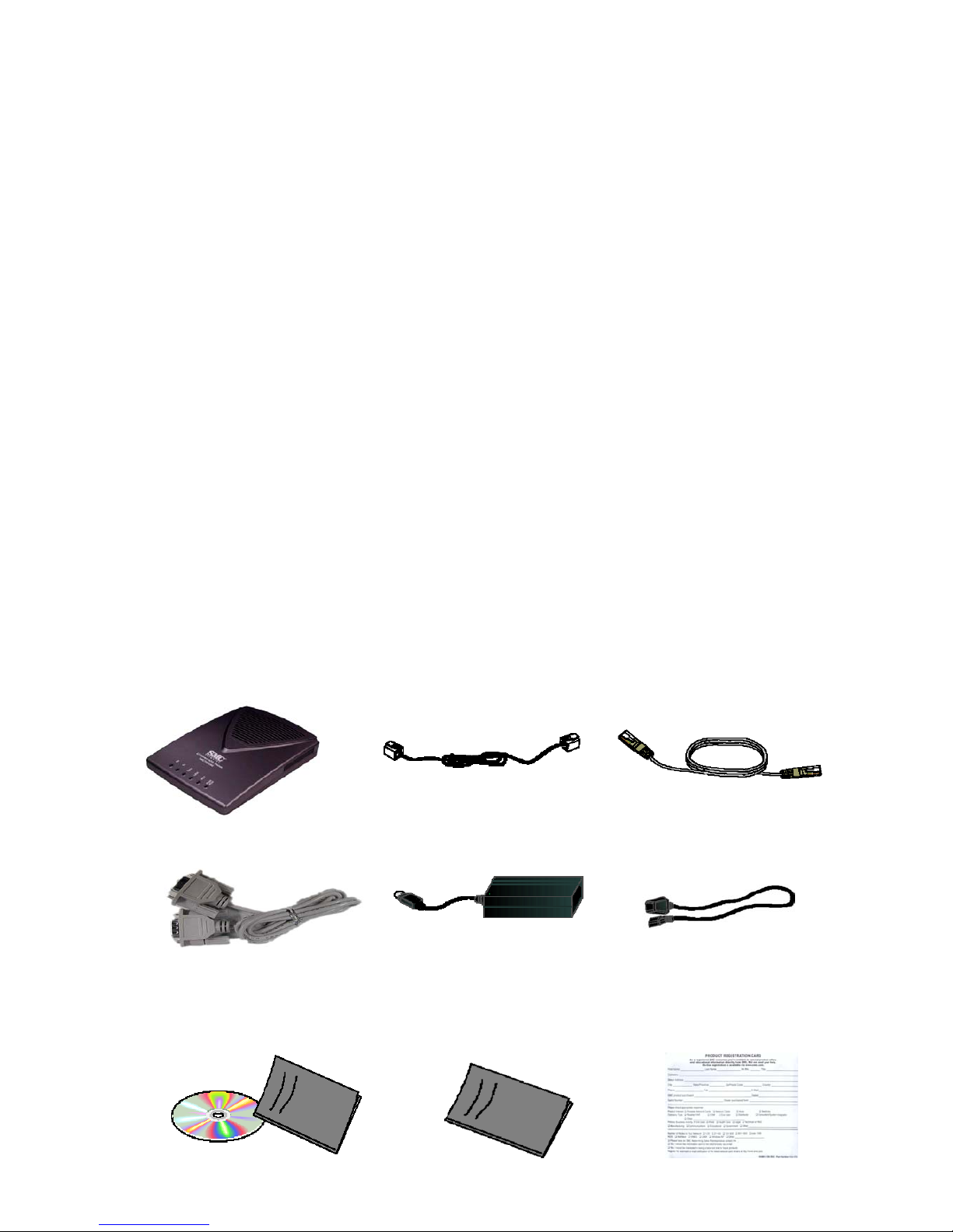
Package Contents
After unpacking the SMC70032AE, check the contents of the box to be sure
you’ve received the following components
① Modem
② RJ-11 phone cord
③ RJ-45 Ethernet cable
④ Console Cable
⑤ Power adapter (110/220V, 60Hz)
⑥ Power cable
⑦ Installation CD with complete User Guide
⑧ Hard copy of the Quick Installation Guide
⑨ SMC Warranty Registration Card
Description of Hardware
① ADSL Modem ② RJ-11 phone cord ③ RJ-45 Ethernet cable
④ Console Cable ⑤ Power adapter (110/220V, 60Hz) ⑥ Power cable
2
⑧ Har stallation ⑨
Gu
SMC Warranty
Registration Card
d copy of the Quick In
ide
⑦ Installation CD with complete
User Guide

LED Indicators
1. Rx: Indicates data is being received.
2.
Tx: Indicates data is being transmitted.
dicates the physical connection between the Modem and the
Service Provider’s DSLAM. While the modem is connecting, the LED will
green) once the connection has
been made.
4.
LINK: Indicates the connection status between the ADSL modem and
5.
nd
d
there is a problem with
connecting to the DSLAM or there is no link to your NIC card or network,
Host
PC
♦ Ethernet 10BaseT or 10/100BaseTX NIC
cal networking
♦
3. Sync: In
blink and then stay in the "ON" state (
the PC or network via the Ethernet connection.
ACT: Indicates data is being transferred between the ADSL modem a
the PC.
6. PWR/ALARM LED: Indicates power is reaching the ADSL modem an
that all functions are operating correctly. If
the ALARM LED light will be Red or will flash Red.
System Requirements
♦ OS which supports the TCP/IP protocol suite
♦ Web browser installed
For lo
Hub, switch, or broadband router
3

CHAPTER 2
ur SMC70032AE
RJ11 connectors, plug one side into the
all jack set up as the ADSL line and the other end in the ‘LINE’ port on the
hernet cable
you are connecting to a networking device, connect a straight-through
Ethernet port. If connecting directly
an initial setup other than the default configuration is required, you will need
s RS-232C port (a DB9 Male port
lug the power cord into the wall and then connect it to the power adapter unit.
will need to connect the 6-pin DIN
Figure 1-1 and Figure 1-2 show how to connect SMC70032AE
ith cables)
Connecting yo
① Step 1: Plug in the phone line
Using a standard telephone cable with
w
back of the SMC70032AE.
② Step 2: Plug in the Et
If
Ethernet cable to the SMC70032AE “LAN”
to your PC, the cable must be a crossover Ethernet cable.
③ Step 3: Connect the console link
If
to use the serial cable to connect the PC’
usually assigned to COM1 or COM2) to the “CONSOLE” port on the back of the
SMC70032AE modem (a DB9 Female port). Setting up the modem requires a
terminal emulation program such as HyperTerminal to access the command line
interface program of the modem. You may also use the Graphical User
Interface included on the SMC70032AE CD.
④ Step 4: Plug in the power supply
P
With the adapter now powered, you
connector from the power adapter to the corresponding “POWER” port on the
SMC70032AE.
(The following
w
4
 Loading...