

Page 1

EZ Connect N
Draft 11n Wireless USB2.0 Adapter
SMCWUSB-N
Page 2

LIMITED WARRANTY
Limited Warranty Statement: SMC Networks, Inc. (“SMC”) warrants its products to be free from
defects in workmanship and materials, under normal use and service, for the applicable
warranty term. All SMC products carry a standard 90-day limited warranty from the date of
purchase from SMC or its Authorized Reseller. SMC may, at its own discretion, repair or
replace any product not operating as warranted with a similar or functionally equivalent
product, during the applic abl e warr an ty te rm. SMC wi ll endeavo r to r epair or replace any
product returned under warranty within 30 days of receipt of the product. The standard limited
warranty can be upgraded to a Limited Lifetime* warranty by registering new products within 30
days of purchase from SMC or its Authorized Reseller. Registration can be accomplished via
the enclosed product regis tra tion card or onli ne vi a t he SMC websi te . Fai lur e to r egist er will not
affect the standard limited warranty. The Limited Lifetime warranty covers a product during the
Life of that Product, which is defined as the period of time during which the product is an
“Active” SMC product. A product is co nsidered to be “Active” w hil e it is listed on the current
SMC price list. As new technologies em erge, ol de r tec hnol ogies bec ome obsol e te and SM C
will, at its discretion, repla c e an ol der p rod uct in its product line with one tha t i ncor pora tes
these newer technologies. At that point, the obsolete product is discontinued and is no longer
an “Active” SMC product. A list of discontinued products with their respective dates of
discontinuance can be found at:
http://www.smc.com/index.cfm ? ac tio n= customer_service_warranty.
All products that are replaced become the property of SMC. Replacement products may be
either new or reconditioned. Any replaced or repaired product car ries eith er a 30 -day l imi ted
warranty or the remainder of the initial warranty, whichever is longer. SMC is not responsible
for any custom software or firmware, configuration information, or memory data of Customer
contained in, stored on, or integrated with any products returned to SMC pursuant to any
warranty. Products returned to SMC should have any customer-installed accessory or add-on
components, such as expansion modules, removed prior to returning the product for
replacement. SMC is not respo nsibl e for th ese it ems if t hey are retu rned with t he produc t.
Customers must contact SMC for a Return Material Authorization number prior to returning any
product to SMC. Proof of purchase may be required. Any product returned to SMC without a
valid Return Material Authorization (RMA) number clearly marked on the outside of the
package will be re t urn ed t o c us tomer at customer’s expense. For warranty claims within No rth
America, please call our toll-free customer support number at (800) 762-4968. Customers are
responsible for all s hipping charges from t h eir facility to SMC. SMC is responsible for return
shipping charges from SMC to cus tom er.
WARRANTIES EXCLUSIVE: IF AN SMC PRODUCT DOES NOT OPERATE AS
WARRANTED ABOVE, CUSTOMER’S SOLE REMEDY SHALL BE REPAIR OR
REPLACEMENT OF THE PRODUCT IN QUESTION, AT SMC’S OPTION. THE FOREGOING
WARRANTIES AND REMEDIES ARE EXCLUSIVE AND ARE IN LIEU OF ALL OTHER
WARRANTIES OR CONDITIONS, EXPRESS OR IMPLIED, EITHER IN FACT OR BY
OPERA TION OF LAW, STATUTORY OR OTHERWISE, INCLUDING W AR RANTIES OR
CONDITIONS OF MERCHANTABILITY AND FITNESS FOR A PARTICULAR PURPOSE.
SMC NEITHER ASSUMES NOR AUTHORIZES ANY OTHER PERSON TO ASSUME FOR IT
ANY OTHER LIABILITY IN CONNECTION WITH THE SALE, INSTALLATION,
MAINTENANCE OR USE OF ITS PRODUCTS. SMC SHALL NOT BE LIABLE UNDER THIS
WARRANTY IF ITS TESTING AND EXAMINATION DISCLOSE THE A LLEGED DEFECT IN
THE PRODUCT DOES NOT EXIST OR W AS CAUSED BY
CUSTOMER’S OR ANY THIRD PERSON’S MISUSE, NEGLECT , IMPROPER INSTALLATION
OR TESTING, UNAUTHORIZED ATTEMPTS TO REPAIR, OR ANY OTHER CAUSE BEYO ND
THE RANGE OF THE INTENDED USE, OR BY ACCIDENT, FIRE, LIGHTNING , OR OTHER
HAZARD.
LIMITATION OF LIABILITY: IN NO EVENT, WHETHER BASED IN CONTRACT OR TORT
(INCLUDING NEGLIGENCE), SHALL SMC BE LIABLE FOR INCIDENTAL,
Page 3

CONSEQUENTIAL, INDIRECT, SPECIAL, OR PUNITIVE DAMAGES OF ANY KIND, OR FOR
LOSS OF REVENUE, LOSS OF BUSINESS, OR OTHER FINANCIAL LOSS ARISING OUT
OF OR IN CONNECTION WITH THE SALE, INSTALLATION, MAINTENANCE, USE,
PERFORMANCE, FAILURE, OR INTERRUPTION OF ITS PRODUCTS, EVEN IF SMC OR
ITS AUTHORIZED RESELLER HAS BEEN A DVISED OF THE POSSIBILITY OF SUCH
DAMAGES. SOME STATES DO NOT ALLOW THE EXCLUSION OF IMPLIED WARRANTIES
OR THE LIMITATION OF INCIDENTAL OR CONSEQUENTIAL DAMAGES FOR
CONSUMER PRODUCTS, SO THE ABOVE LIMITATIONS AND EXCLUSIONS MAY NOT
APPLY TO YOU. THIS WARRANTY GIVES YOU SPECIFIC LEGAL
RIGHTS, WHICH MAY VARY FROM STATE TO ST ATE. NOTHING IN THIS WARRANTY
SHALL BE T AKEN T O AFFECT YOUR STATUTORY RIGHTS.
* SMC will provide warranty service fo r one y ear follo wing di sconti n uanc e from th e acti v e
SMC price list. Under the limited lifetime warranty, internal and external power supplies, fans,
and cables are covered by a standard one-year warranty from date of purchase.
SMC Networks, Inc.
20 Mason
Irvine, CA 92618
2
Page 4

Compliances
Federal Communication Commission I nter fer ence S tatement
This equipment has been teste d and f ou nd to compl y wit h the limi t s f or a Class B digi t al dev ice,
pursuant to Part 15 of the FC C Rules. These limit s are desi gn ed to prov ide reas ona bl e
protection against h armfu l interference in a r esi de n ti al installation. This equipment generates,
uses and can radiate radio f req uenc y en ergy an d, if not i nstalled and used in accordance wit h
the instructions, may cause harmful interference to radio communications. However, there is no
guarantee that interference will not occur in a particular installation. If this equipment does
cause harmful interference to radio or television reception, which can be determined by turning
the equipment of f an d on, th e us er is enco urag ed to try to co rrec t t he int erfe re nce by one or
more of the following measures:
• Reorient or relocate the receiving antenna.
• Increase the distance between the equipment and receiver.
• Connect the equipment into an outlet on a circuit different from that to which the receiver is
connected.
• Consult the dealer or an experi e nced radi o /TV technic ian for h el p.
FCC Caution: To assure continued compliance, (example - use only shielded interface cables
when connecting to computer or peripheral devices) any changes or modifications not
expressly approved by the party responsible for compli ance coul d void the use r’s authori ty to
operate this equipment.
This device complies wi th P ar t 1 5 of the FCC Rules. Opera tion is subject to the follo wi n g two
conditions: (1) This device may no t ca us e ha rmful interference, and (2 ) t his d evice must accept
any interference received, including interference that may cause undesired operation.
IMPORTANT NOTE
FCC Radiation Exposure Statement:
This equipment complies with FCC radi ati on expos ur e limit s set fort h for an unc ontrol le d
environment. This transmitter must not be co-located or operating in conjunction with any other
antenna or transmitter.
CE Mark Declaration of Conformance for EMI and Safety (EEC)
This device complies with t h e essential requirement s of the R&TTE Directive 19 99 / 5/ EC.
The following refe rences have been applied in order to prove presumption of complianc e with
the R&TTE Directive 1999/5/EC:
• EN 300 328
• EN 301 489-1
• EN 301 489-17
• EN 60950-1
A copy of the CE Declaration of Conformity is available for download at: http://www.smc.com
Intended for indoor use in the following countries:
AT, BE, CZ, CY, DK, EE, FI, FR, DE, GR, HU, IS, IE, IT, LV, LT, LU, MT, NL, NO, PL, PT, SI,
SK, ES, SE, CH, UK.
3
Page 5

Table of Contents
Chapter 1 – Wireless LAN Networking
Transmission Rate 5
Type of Wireless Networks 5
Ad-Hoc (IBSS) Network 5
Infrastructure (BSS) Network 6
Wireless LAN Security 9
Data Encryption with WEP 10
Chapter 2 - Getting Started
About Your Draft 11n Wireless USB2.0 Adapter 11
Package Content 11
System Requirement 12
LED Definition 12
Wireless Utility and Adapter Hardware Installation 12
Using the Utility to Configure Your Network 16
Link Information 16
Site Survey 18
Profile 19
WPS 23
Chapter 3 – Maintenance
Uninstalling the Driver 28
Uninstall the Client Utility 28
Upgrading the Wireless Utility 28
Glossary 29
4
Page 6

Chapter 1- Wireless LAN Networking
This section provides background information on wireless LAN networking technology.
T
HE INFORMATION IN THIS SECTION IS FOR YOUR REF ER ENC E. CHANGING
NETWORK SETTINGS AND P ARTICULARL Y SECURITY SETTTINGS SHOU LD
ONLY BE DONE BY AN AUTHORIZED ADMINISTRA T OR.
Transmission Rate (Transfer Rate)
The adapter provides various transmission (data) rate options for you to select. In most
networking scenarios, the factory default Fully Auto setting proves the most efficient. This
setting allows your adapter to operate at the maximum transmission (data) rate. When the
communication quality drops below a certain level, the adapter automatically switches to a
lower transmission (data) rate. Transmission at lower data speeds is usually more reliable.
However, when the communication quality improves again, the adapter gradually increases
the transmission (data) rate again until it reaches the highest available transmission rate.
Types of Wireless Networks
Wireless LAN networking works in either of the two modes: ad-hoc and infrastructure. In
infrastructure mode, wireless devices communicate to a wired LAN via access points. Each
access point and its wireless devices are known as a Basic Service Set (BSS). An Extended
Service Set (ESS) is two or more BSSs in the same subnet. In ad hoc mode (also known as
peer-to-peer mode), wireless devices communicate with each other directly and do not use
an access point. This is an Independent BSS (IBSS).
To connect to a wired network within a coverage area using access points, set the adapter
operation mode to Infrastructure (BSS). To set up an independent wireless workgroup without
an access point, use Ad-hoc (IBSS) mode.
A
D-HOC (IBSS) NETWORK
Ad-hoc mode does not require an access point or a wired network. Two or more wireless
stations communicate directly to each other. An ad-hoc network may sometimes be referred
to as an Independent Basic Service Set (IBSS).
To set up an ad-hoc network, configure all the stations in ad-hoc mode. Use the same SSID
and channel for each.
5
Page 7
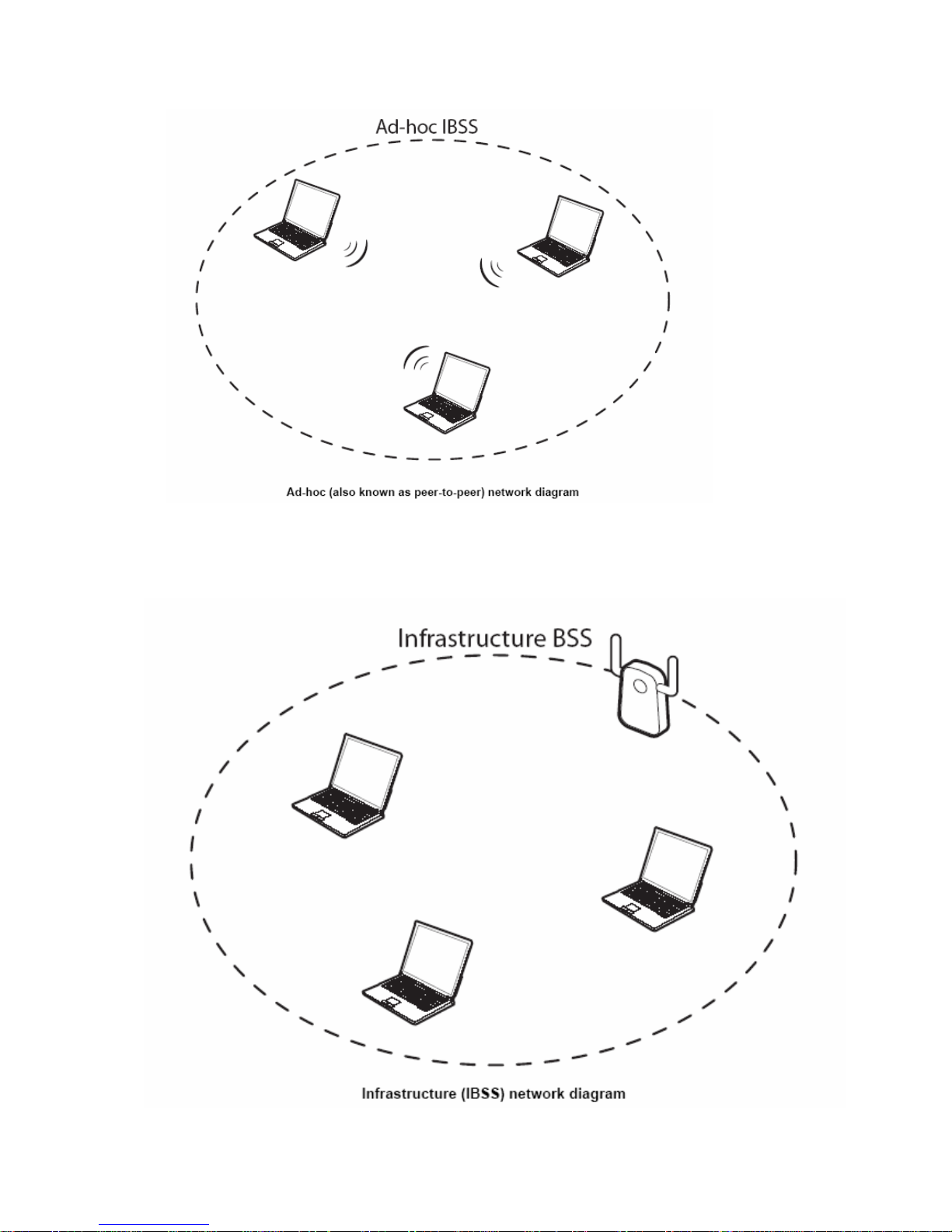
When a number of wireless stations are connected using a single access point, you have a
Basic Service Set (BSS).
6
Page 8
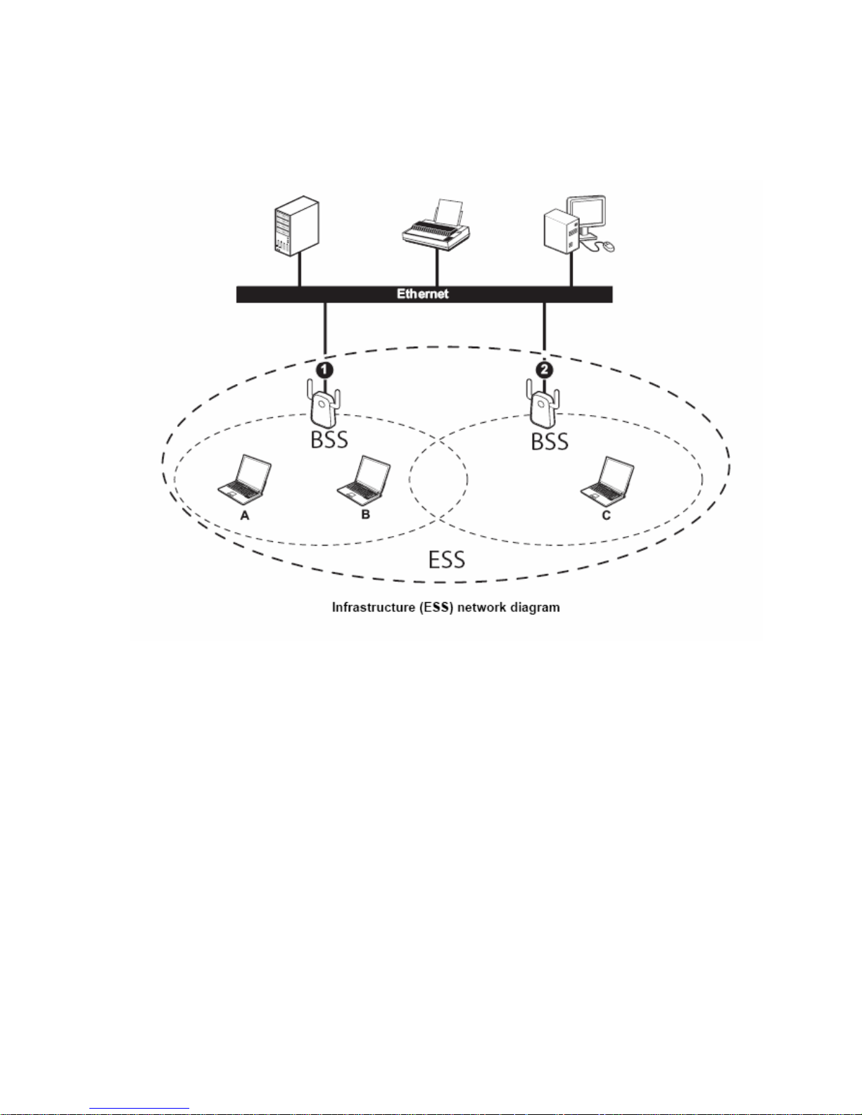
In the ESS diagram below, communication is done through the access points, which relay
data packets to other wireless stations or devices connected to the wired network. Wireless
stations can then access resources, such as a printer, on the wired network.
7
Page 9
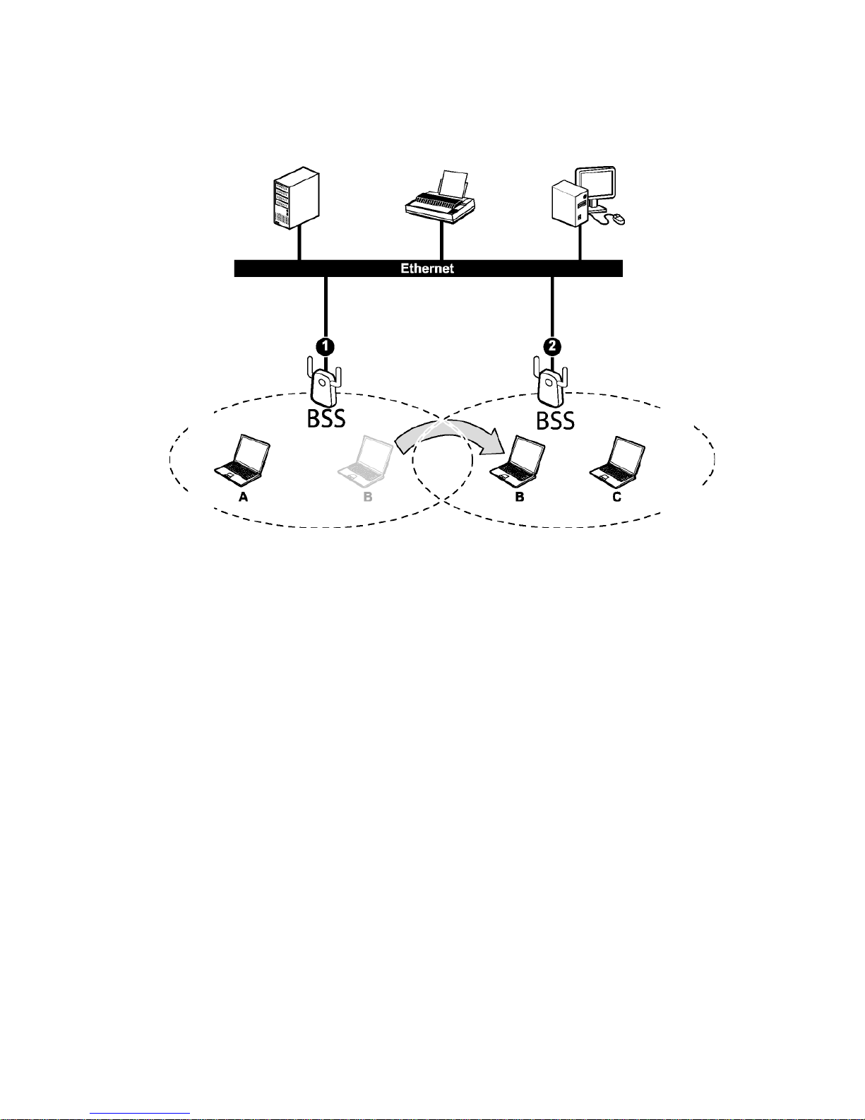
In an ESS environment, users are able to move from one access point to another without
losing the connection. In the diagram below, when the user moves from BSS (1) to BSS (2)
the adapter automatically switches to the channel used in BSS (2).
Roaming in an ESS network diagram
8
Page 10

WIRELESS LAN SECURITY
Because wireless networks are not as secure as wired networks, it’s vital that security settings are clearly
understood and applied.
The list below shows the possible wireless security levels on your adapter starting with the most secure. EAP
(Extensible Authentication Protocol) is used for authentication and utilizes dynamic WEP key exchange. EAP
requires interaction with a RADIUS (Remote Authentication Dial-In User Service) server either on the WAN
or the LAN to provide authentication service for wireless stations.
1. Wi-Fi Protected Access (WPA)
2. IEEE802.1X EAP with RADIUS Server authentication
3. WEP Encryption
4. Unique ESSID
9
Page 11

D
ATA
ENCRYPTION WITH WEP
The WEP (Wired Equivalent Privacy) security protocol is an encryption method designed to try to make
wireless networks as secure as wired networks. WEP encryption scrambles all data packets transmitted
between the adapter and the access point or other wireless stations to keep network communications private.
Both the wireless stations and the access points must use the same WEP key for data encryption and
decryption.
There are two ways to create WEP keys in your adapter.
DO NOT ATTEMPT TO C ONFI GU RE OR CHANGE SECURITY SETTTIN GS F OR A
NETWORK WITHOUT AUTHORIZATION AND WITHOUT CLEARLY UNDERSTANDING
THE SETTINGS YOU ARE APPLING.
WITH POOR SECURITY SETTINGS, SE NSITI VE
• Automatic WEP key generation based on a password phrase called a passphrase. The passphrase is
case sensitive. You must use the same passphrase for all WLAN adapters with this feature in the
same WLAN.
• For WLAN adapters without the passphrase feature, you can still take advantage of this feature by
writing down the four automatically generated WEP keys from the Securi ty Settings screen of the
wireless utility and entering them manually as the WEP keys in the other WLAN adapter(s).
The adapter allows you to configure up to four WEP keys and only one key is used as the default transmit
key at any one time.
T
HE adapter SUPPORTS UP TO FOUR 64-BIT or 128-BIT WEP KEYS.
10
Page 12

Chapter 2 - Getting Started
2.1 About Your Draft 11n Wireless USB2.0 Adapter
The EZ Connect™ N Draft 11n Wireless USB2.0 Adapter (SMCWUSB-N) is another cutting edge introduction
in 2.4GHz wireless communication for desktop and notebook computers. Designed for both the home and
office, this wireless USB2.0 adapter provides the speed, coverage and security expected by today's wireless
users. The SMCWUSB-N is 802.11n draft v2.0 compliant while maintaining full backwards compatibility with
the Wireless-G (802.11g) and Wireless-B (802.11b) standards. This next generation standard utilizes
advanced MIMO (Multiple-In, Multiple-Out) technology to deliver incredible speed and range. With wireless
speeds up to 300Mbps and extended coverage, there is enough bandwidth to simultaneously stream video
and audio, play online games, transfer large files, make VoIP calls and surf the Internet. With security being a
key consideration, SMCWUSB-N supports the latest WPA and WPA2 wireless encryption standards, which
prevent unauthorized access to wireless networks and ensure data is secure. Wireless security can also be set
up easily using Wi-Fi Protected Setup
SMCWUSB-N includes an easy installation wizard which guides you step-by-step through the process. Once
installed the WLAN utility allows you to scan for available wireless networks and manage multiple network
profiles so connecting becomes instantaneous.
The following lists the main features:
TM
(WPS) that enables push button or PIN configuration. The
• IEEE802.11n draft v2.0 compliant
• Wireless speeds up to 300Mbps
• Increased speeds & coverage - up to 5x the speed of 802.11g
• Fully backwards compatible with 802.11b/g wireless networks
• Stream HD video, Listen to digital music, Play online games, Transfer large files, Make VoIP calls &
Surf the Internet simultaneously
• WEP 64-/128-Bit, WPA & WPA2 wireless encryption
• EZ Installation Wizard for easy installation
• Supports Windows 2000/XP/Vista
• WLAN management utility
2.2 Package Contents
• EZ Connect™ N Wireless USB 2.0 Adapter (SMCWUSB-N)
• EZ Installation Wizard & Documentation CD
11
Page 13

• Quick Installation Guide
• Warranty Information Card
2.3 System Requirements
• 2.4 GHz 802.11n draft wireless network or 2.4 GHz 802.11b/g wireless network
• Microsoft Windows 2000, XP or Vista
• A Notebook or Desktop computer with:
o 300MHz CPU or above
o Available USB2.0 port
o 20MB of available hard disk space
• CD-ROM drive
2.4 LED Definition
The following table describes the LED on behavior:
COLOR STATUS DESCRIPTION
OFF No power
Blue
ON Wireless connected without data traffic
Slow Blinking Power on without wireless connection
Normal Blinking Wireless connected with data traffic
2.5 Wireless Utility & Adapter Hardware Installation
IMPORTANT: Do not plug in the EZ Connect™ N Wireless USB2.0 Adapter until instructed.
Follow the instructions below to install the USB Adapter and Utility.
STEP 1
Put the EZ Installation & Documentation CD in to your CD-ROM drive. The CD will auto run.
STEP 2
Click [Install Driver/Utility] and follow the on-screen instructions. Note: During installation a “Software
Installation” warning may appear, click [Continue Anyway].
12
Page 14

STEP 3
The InstallShield Wizard prompts you for confirmation. Click Next on the following screen.
STEP 4
In the destination Folder screen you are asked to confirm the Destination Folder for the application software.
If you would like, you may change the destination folder to another location. Click Next
13
Page 15

STEP 5
The wizard is ready to begin installation. Click Install on it.
STEP 6
Click Finish to complete the client utility installation.
STEP 7
After clicking [Finish] the Wizard will exit. Plug in the EZ Connect™ N Wireless USB2.0 Adapter to an
available USB port. The “Found New Hardware Wizard” will appear. Click [No, not this time], then [Next].
14
Page 16

STEP 8
Click [Install the software automatically (Recommended)], then click [Next]. A “Hardware Installation” warning
may appear, click [Continue Anyway].
STEP 9
Click [Finish] to complete the Driver/Utility installation.
15
Page 17

2.6 Using the Utility to Configure Your Network
The following are explanations on how to configure and use the Utility program. After completing the
installation procedure, a new icon as shown below will automatically appear in the lower right tray bar.
Hold your mouse pointer over the icon, and press the right mouse button to open the Wireless Client Utility.
The Wireless Client Utility window as shown below will appear.
The user can now use any of the management functions available in the IEEE 802.11 Wireless Client Utility.
2.6.1 Link Information
Click the Link Information tab to see general information about the program and its operations. The Link
Information tab does not require any configuration.
16
Page 18

The following table describes the items found on the Link Information screen.
Wireless Network Status
Profile Name
The name of the current selected configuration profi l e. Set up th e
configuration name on the Profile tab.
Displays the wireless network name.
SSID
Link Status
Network Type
Shows whether the station is associated to the wireless network.
The type of network the station is connected to. The options
include:
Infrastructure (access point)
Ad Hoc
Wireless Mode
Channel
Transmit Rate
AP MAC Address
Signal Strength
Security
Authentication
IP Address
Subnet Mask
Gateway
Displays the wireless mode: 802.11n, 11g or 11b.
Shows the currently connected channel.
Displays the current transmit rate in Mbps.
Displays the MAC address of the access point the wireless
adapter is associated to.
Shows the strength of the signal.
Security Status
Shows the security type – Disable, WEP, WPA/WPA2,
WAP-PSK/WAP2-PSK or 802.1X
Displays the authentication mode.
TCP/IP Status
Displays the computer's IP address.
Displays subnet mask
Displays gateway address
17
Page 19

2.6.2 Site Survey
Click the Site Survey tab to see available infrastructure and ad hoc networks. On this screen, click Refresh
to refresh the list at any time.
Connecting to a different network
Hold your mouse pointer over the network icon, and click the right mouse button to select the network.
Click the Connect button to connect the available network. If no configuration profile exists for that
network, the Profile Settings window opens to ask to create a profile for the network. Follow the
procedures to create profile for that network.
18
Page 20

2.6.3 Profile
To add a new configuration profile, click Add on the Profile tab.
To modify a configuration profile, select the configuration from the Profile list and click the Edit button.
Scan Available Networks
Click the Browse button on the Profile Settings screen to scan for available infrastructure and ad hoc
networks. On this list, click Refresh to refresh the list at any time.
19
Page 21

To configure a profile for Ad-Hoc or Infrastructure mode, select the Network Type field on the Profile
Settings.
Click Next to continue the profile setting.
To define the security mode, select the security button of the desired security mode. And then click Next to
continue. Please see following table for details of security modes.
WPA/WPA2
Enables the use of Wi-Fi Protected Access (WPA).
Choosing WPA/WPA2 opens the WPA/WPA2 Security Settings
screen. The options include:
20
Page 22

TLS (Transport Layer Security) is a Point-to-Point Protocol
(PPP) extension supporting additional authentication methods
within PPP. Transport Layer Security (TLS) provides for mutual
authentication, integrity-protected cipher suite negotiation, and key
exchange between two endpoints
.
PEAP (EAP-GTC) (Protected Extensible Authentication
Protocol) authenticates wireless LAN
server
-side digital certificates by creating an encrypted SSL/TLS
tunnel between the clie nt and the authentication
then protects the subsequent user authentication exchange.
clients using only
server. The tunnel
PEAP (EAP-MSCHAP V2) (Protected Extensible
Authentication Protocol)
To use PEAP (EAP-MSCHAP V2)
security, the server must have WPA-PEAP certificat es, and
the server properties must already be set. Check with the IT
manager
TTLS (Tunneled Transport Layer Security) An EAP variant that
provides mutual authentication using a certificate for server
authentication, and via a secure TLS
tunnel for the client
LEAP (Lightweight and Efficient Application Protocol)
is the general framework for a set of high-performance,
efficient protocols which are ideal for mobile and wireless
applications. LEAP is designed to address all the technical
requirements of the wireless data communications industry,
and is oriented towards providing the greatest benefit to the
industry and the consumer
WPA-PSK/WPA2-PSK
Enables WPA/WPA2 Passphrase security.
Fill in the WPA/WPA2 Passphrase on Security Settings screen.
802.1x
Enables 802.1x security. This option requires IT administration.
Choosing 802.1x opens the 802.1x Security Settings screen. The
options include:
TLS
PEAP
TTLS
LEAP
Advanced Settings
After Security Settings finished, the Advanced Settings screen will be shown as following.
21
Page 23

The following table describes the items found on the Advanced Settings screen.
Power Save Mode
802.11b Preamble
Shows the power save mode. Power management is disabled in ad
hoc mode.
z Continuous Access Mode
z
z
The options include:
Maximum Power Saving
Fast Power Saving
Displays the 802.11b preamble format.
The options include:
z Long
z Short
z Auto
RTS Threshold
Value from 0 ~ 2347
FRAG Threshold Value from 256 ~ 2346
Wireless Mode
Include:
z 802.11b
z 802.11g
z 802.11n
After advance settings are finished, the following screen showed as below.
You can activate the profile now or later.
22
Page 24

2.6.4 WPS Setting
The user obtains a device password (PIN Code) from the STA and enters the password into the Registrar.
Both the Enrollee and the Registrar use PIN Config method for the configuration setup. The detail indicates
as follows.
23
Page 25

24
Page 26

1. Go to the WPS setting page, c
2. Select an AP (SSID/BSSID) that STA want join to.
lick "Refresh" button to update available WPS APs.
3. Click "PIN" button to start PIN connection.
25
Page 27

4. Enter PIN Code of STA into the Registrar when prompted by the Registrar.
5. The result will look like the below figure.
26
Page 28

6. Then connect successfully. The result will look like the below figure.
WPS Status Bar Description:
1. A successful PIN configuration :
Start PIN connection - SSID ~> Begin associating to WPS AP ~> Associated to WPS AP ~>
Sending EAPOL-Start ~> Sending EAP-Rsp (ID) ~> Receive EAP-Req (Start) ~> Sending
M1 ~> Received M2 ~> (Received M2D ~> Sending EAP-Rsp (ACK)) ~> Sending M3 ~>
Received M4 ~> Sending M5 ~> Received M6 ~> Sending M7 ~> Received M8 ~> Sending
EAP-Rsp(Done) ~> Configured ~> WPS status is disconnected ~> WPS status is connected
successfully-SSID
2. WPS configuration doesn't complete after two-minute connection:
WPS Eap process failed.
3. When Errors occur within two-minute connection, the WPS status bar might report on
"WPS Eap process failed".
Error messages might be:
1. Receive EAP with wrong NONCE.
27
Page 29

2. Receive EAP without integrity.
3. Error PIN Code.
4. An inappropriate EAP-FAIL received.
Chapter 3 – Maintenance
This chapter describes how to uninstall or upgrade the Wireless Utility.
3.1 Uninstall the Driver
Follow the steps below to remove (or uninstall) the USB Adapter driver from your computer.
Step 1. To remove the driver from the OS, go to Start -> Control Panel
Step 2. Double-click System
Step 3. Under Hardware tab, click Device Manager.
Step 4. Double-click Network Adapter
Step 5. Right-click mouse button on “802.11n USB Wireless Network Adapter”, and
choose Uninstall
Step 6. Click OK to confir m that you are going to uninstall the driver
3.2 Uninstall the Client Utility
Follow the steps below to remove the Client Utility from your computer.
Step 1. To remove the utility from the OS, go to Start -> Control Panel
Step 2. Double-click Add-Remove Programs
Step 3. Select 802.11n Wireless Client Utility, and click the Remove button
3.3 Upgrading the Wireless Utility
To perform the upgrade, follow the steps below.
Step 1. Download the latest version of the utility from the web site and save the file on your
computer.
Step 2. Follow the steps in Section 2.2 to remove the current Wireless Utility from your
computer.
Step 3. Restart your computer if prompted.
Step 4. After restarting, refer to the procedure in the Chapter 2 to install the new utility.
28
Page 30

Glossary
For unfamiliar terms used below, look for entries elsewhere in the glossary.
AD-HOC (IBSS)
Ad-hoc mode does not require an AP or a wired network. A network that transmits
wireless from computer to computer without the use of a base station (access point).
Two or more wireless stations communicate directly to each other. An ad-hoc network
may sometimes be referred to as an Independent Basic Service Set (IBSS).
CHANNEL
A radio frequency used by a wireless device is called a channel.
EAP AUTHENTICATION
EAP (Extensible Authentication Protocol) is an authentication protocol that runs on top of
the IEEE802.1X transport mechanism in order to support multiple types of user
authentication. By using EAP to interact with an EAP-compatible RADIUS server, an
access point helps a wireless station and a RADIUS server perform authentication.
ENCRYPTION
The reversible transformation of data from the original to a difficult-to-interpret format.
Encryption is a mechanism for protecting confidentiality, integrity, and authenticity of data.
It uses an encryption algorithm and one or more encryption keys.
FRAGMENTATION THRESHOLD
This is the maximum data fragment size that can be sent before the packet is fragmented
into smaller packets.
IEEE 802.1X
The IEEE 802.1X standard outlines enhanced security methods for both the authentication
of wireless stations and encryption key management. Authentication can be done using an
external RADIUS server.
INFRASTRUCTURE (BSS)
When a number of wireless stations are connected using a single AP, you have a Basic
Service Set (BSS).
29
Page 31

ROAMING
In an infrastructure network, wireless stations are able to switch from one BSS to another
as they move between the coverage areas. During this period, the wireless stations
maintain uninterrupted connection to the network. This is roaming. As the wireless station
moves from place to place, it is responsible for choosing the most appropriate AP
depending on the signal strength, network utilization among other factors.
SSID
The SSID (Service Set Identity) is a unique name shared among all wireless devices in a
wireless network. Wireless devices must have the same SSID to communicate with each
other.
TEMPORAL KEY INTEGRITY PROTOCOL (TKIP)
Temporal Key Integrity Protocol (TKIP) uses 128-bit keys that are dynamically generated and
distributed by the authentication server.
USER AUTHENTICATION
WPA applies IEEE 802.1X and Extensible Authentication Protocol (EAP) to authenticate
wireless clients using an external RADIUS database. If you do not have an external RADIUS
server, use WPA-PSK/WPA2-PSK (WPA -Pre-Shared Key) that only requires a single (identical) password entered into each access point, wireless gateway and wireless client. As long
as the passwords match, clients will be granted access to a WLAN.
WEP
WEP (Wired Equivalent Privacy) encryption scrambles all data packets transmitted between
the WCB-321A and the AP or other wireless stations to keep network communications private. Both the wireless stations and the access points must use the same WEP key for data
encryption and decryption.
WPA/WPA2
Wi-Fi Protected Access (WPA) and WPA2 (future upgrade) is a subset of the IEEE 802.11i
security specification draft. Key differences between WPA and WEP are user authentication
and improved data encryption. WPA2 is a wireless security standard that defines stronger
encryption, authentication and key management than WPA.
30
Page 32

SMCWUSB-N
SMCWBR11-G
 Loading...