

SMC Networks EX9-OET1,EX9-OET2,EX9-OEP1,EX9-OEP2,EX9-PE1 Operation Manual
No.EX※※-OMH0025-C
PRODUCT NAME
Output block / Power block
MODEL / Series / Product Number
EX9-OET1
EX9-OET2
EX9-OEP1
EX9-OEP2
EX9-PE1

-1-
No.EX※※-OMH0025-C
Table of Contents
Safety Instructions 2
Model Indication and How to Order 8
Product Outline 8
Summary of Product elements 9
Product Selection 11
Selection for low wattage and high wattage load 11
EX9-OET (Output block for low wattage load) 13
EX9-OEP (Output block for high wattage load) 14
Polarity 15
The number of connected stations 15
Limit of output points when the Output block for high wattage load
and Power block are used 16
Supply current 19
Connection of inductive load 28
Mounting and Installation 29
Mounting 29
Installation 29
Wiring 30
LED Indication 40
Maintenance 41
Troubleshooting 42
Specification 43
Specifications 43
Dimensions 45
Accessories 49
-2-
No.EX※※-OMH0025-C
Safety Instructions
These safety instructions are intended to prevent hazardous situations and/or equipment damage.
These instructions indicate the level of potential hazard with the labels of "Caution", "Warning" or "Danger".
They are all important notes for safety and must be followed in addition to International Standards
(ISO/IEC)*1), and other safety regulations.
*1) ISO 4414: Pneumatic fluid power -- General rules relating to systems.
ISO 4413: Hydraulic fluid power -- General rules relating to systems.
IEC 60204-1: Safety of machinery -- Electrical equipment of machines. (Part 1: General requirements)
ISO 10218: Manipulating industrial robots -Safety.
etc.
Caution
Caution indicates a hazard with a low level of risk which, if not avoided, could
result in minor or moderate injury.
Warning
Warning indicates a hazard with a medium level of risk which, if not avoided,
could result in death or serious injury.
Danger
Danger indicates a hazard with a high level of risk which, if not avoided, will
result in death or serious injury.
Warning
1. The compatibility of the product is the responsibility of the person who designs the
equipment or decides its specifications.
Since the product specified here is used under various operating conditions, its compatibility with specific
equipment must be decided by the person who designs the equipment or decides its specifications
based on necessary analysis and test results.
The expected performance and safety assurance of the equipment will be the responsibility of the person
who has determined its compatibility with the product.
This person should also continuously review all specifications of the product referring to its latest catalog
information, with a view to giving due consideration to any possibility of equipment failure when
configuring the equipment.
2. Only personnel with appropriate training should operate machinery and equipment.
The product specified here may become unsafe if handled incorrectly.
The assembly, operation and maintenance of machines or equipment including our products must be
performed by an operator who is appropriately trained and experienced.
3. Do not service or attempt to remove product and machinery/equipment until safety is
confirmed.
1. The inspection and maintenance of machinery/equipment should only be performed after measures to
prevent falling or runaway of the driven objects have been confirmed.
2. When the product is to be removed, confirm that the safety measures as mentioned above are
implemented and the power from any appropriate source is cut, and read and understand the specific
product precautions of all relevant products carefully.
3. Before machinery/equipment is restarted, take measures to prevent unexpected operation and malfunction.
4. Contact SMC beforehand and take special consideration of safety measures if the
product is to be used in any of the following conditions.
1. Conditions and environments outside of the given specifications, or use outdoors or in a place
exposed to direct sunlight.
2. Installation on equipment in conjunction with atomic energy, railways, air navigation, space, shipping,
vehicles, military, medical treatment, combustion and recreation, or equipment in contact with food and
beverages, emergency stop circuits, clutch and brake circuits in press applications, safety equipment or
other applications unsuitable for the standard specifications described in the product catalog.
3. An application which could have negative effects on people, property, or animals requiring special
safety analysis.
4. Use in an interlock circuit, which requires the provision of double interlock for possible failure by using
a mechanical protective function, and periodical checks to confirm proper operation.
-3-
No.EX※※-OMH0025-C
Safety Instructions
Caution
1.The product is provided for use in manufacturing industries.
The product herein described is basically provided for peaceful use in manufacturing industries.
If considering using the product in other industries, consult SMC beforehand and exchange
specifications or a contract if necessary.
If anything is unclear, contact your nearest sales branch.
Limited warranty and Disclaimer/Compliance Requirements
The product used is subject to the following "Limited warranty and Disclaimer" and "Compliance
Requirements".
Read and accept them before using the product.
Limited warranty and Disclaimer
1. The warranty period of the product is 1 year in service or 1.5 years after the product is
delivered, whichever is first.2)
Also, the product may have specified durability, running distance or replacement parts.
Please consult your nearest sales branch.
2. For any failure or damage reported within the warranty period which is clearly our
responsibility, a replacement product or necessary parts will be provided.
This limited warranty applies only to our product independently, and not to any other
damage incurred due to the failure of the product.
3. Prior to using SMC products, please read and understand the warranty terms and
disclaimers noted in the specified catalog for the particular products.
2) Vacuum pads are excluded from this 1 year warranty.
A vacuum pad is a consumable part, so it is warranted for a year after it is delivered.
Also, even within the warranty period, the wear of a product due to the use of the
vacuum pad or failure due to the deterioration of rubber material are not covered by the
limited warranty.
Compliance Requirements
1. The use of SMC products with production equipment for the manufacture of weapons of
mass destruction (WMD) or any other weapon is strictly prohibited.
2. The exports of SMC products or technology from one country to another are governed by
the relevant security laws and regulation of the countries involved in the transaction. Prior
to the shipment of a SMC product to another country, assure that all local rules governing
that export are known and followed.
-4-
No.EX※※-OMH0025-C
Operator
This operation manual is intended for those who have knowledge of machinery using pneumatic
equipment, and have sufficient knowledge of assembly, operation and maintenance of such
equipment. Only those persons are allowed to perform assembly, operation and maintenance.
Read and understand this operation manual carefully before assembling, operating or providing
maintenance to the product.
■Safety Instructions
Warning
■Do not disassemble, modify (including changing the printed circuit board) or repair.
An injury or failure can result.
■Do not operate the product outside of the specifications.
Do not use for flammable or harmful fluids.
Fire, malfunction, or damage to the product can result.
Verify the specifications before use.
■Do not operate in an atmosphere containing flammable or explosive gases.
Fire or an explosion can result.
This product is not designed to be explosion proof.
■If using the product in an interlocking circuit:
•Provide a double interlocking system, for example a mechanical system.
•Check the product regularly for proper operation.
Otherwise malfunction can result, causing an accident.
■The following instructions must be followed during maintenance:
•Turn off the power supply.
•Stop the air supply, exhaust the residual pressure and verify that the air is released before performing
maintenance.
Otherwise an injury can result.
-5-
No.EX※※-OMH0025-C
Caution
■After maintenance is complete, perform appropriate functional inspections.
Stop operation if the equipment does not function properly.
Safety cannot be assured in the case of unexpected malfunction.
■Provide grounding to assure the noise resistance of the product.
Individual grounding should be provided close to the product with a short cable.
■NOTE
○Follow the instructions given below when designing, selecting and handling the product.
The instructions on design and selection (installation, wiring, environment, adjustment, operation,
maintenance, etc.) described below must also be followed.
Product specifications
•When conformity to UL is required, the SI unit should be used with a UL1310 Class 2 power supply.
•The SI unit is a UL approved product only if they have a mark on the body.
•Use the specified voltage.
Otherwise failure or malfunction can result.
•Reserve a space for maintenance.
Allow sufficient space for maintenance when designing the system.
•Do not remove any nameplates or labels.
This can lead to incorrect maintenance, or misreading of the operation manual, which could cause damage or
malfunction to the product.
It may also result in non-conformity to safety standards.

-6-
No.EX※※-OMH0025-C
Product handling
Installation
•Do not drop, hit or apply excessive shock to the product.
Otherwise damage to the product can result, causing malfunction.
•Tighten to the specified tightening torque.
If the tightening torque is exceeded the mounting screws may be broken.
IP67 protection cannot be guaranteed if the screws are not tightened to the specified torque.
•Never mount a product in a location that will be used as a foothold.
The product may be damaged if excessive force is applied by stepping or climbing onto it.
Wiring
•Avoid repeatedly bending or stretching the cables, or placing heavy load on them.
Repetitive bending stress or tensile stress can cause breakage of the cable.
•Wire correctly.
Incorrect wiring can break the product.
•Do not perform wiring while the power is on.
Otherwise damage to the product and/or I/O device can result, causing malfunction.
•Do not route wires and cables together with power or high voltage cables.
Otherwise the product and/or I/O device can malfunction due to interference of noise and surge voltage from power
and high voltage cables to the signal line.
Route the wires (piping) of the product and/or I/O device separately from power or high voltage cables.
•Confirm proper insulation of wiring.
Poor insulation (interference from another circuit, poor insulation between terminals, etc.) can lead to excess
voltage or current being applied to the product, causing damage.
•Take appropriate measures against noise, such as using a noise filter, when the product is incorporated
into equipment.
Otherwise noise can cause malfunction.
Environment
•Select the proper type of protection according to the environment of operation.
IP67 protection is achieved when the following conditions are met.
(1) The units are connected properly with product cable with M12 connector and power cable with M12 connector.
(2) Suitable mounting of each unit and manifold valve.
If using in an environment that is exposed to water splashes, please take measures such as using a cover.
•Do not use in a place where the product could be splashed by oil or chemicals.
If the product is to be used in an environment containing oils or chemicals such as coolant or cleaning solvent, even
for a short time, it may be adversely affected (damage, malfunction etc.).
•Do not use the product in an environment where corrosive gases or fluids could be splashed.
Otherwise damage to the product and malfunction can result.
•Do not use in an area where surges are generated.
If there is equipment which generates a large amount of surge (solenoid type lifter, high frequency induction furnace,
motor, etc.) close to the product, this may cause deterioration or breakage of the internal circuit of the product. Avoid
sources of surge generation and crossed lines.
•When a surge-generating load such as a relay or solenoid is driven directly, use an product with a built-in
surge absorbing element.
Direct drive of a load generating surge voltage can damage the product.
•The product is CE marked, but not immune to lightning strikes. Take measures against lightning strikes
in the system.
•Prevent foreign matter such as remnant of wires from entering the product to avoid failure and
malfunction.

-7-
No.EX※※-OMH0025-C
•Mount the product in a place that is not exposed to vibration or impact.
Otherwise failure or malfunction can result.
•Do not use the product in an environment that is exposed to temperature cycle.
Heat cycles other than ordinary changes in temperature can adversely affect the inside of the product.
•Do not expose the product to direct sunlight.
If using in a location directly exposed to sunlight, shade the product from the sunlight.
Otherwise failure or malfunction can result.
•Keep within the specified ambient temperature range.
Otherwise malfunction can result.
•Do not operate close to a heat source, or in a location exposed to radiant heat.
Otherwise malfunction can result.
Adjustment and Operation
•Perform settings suitable for the operating conditions.
Incorrect setting can cause operation failure.
•Please refer to the PLC manufacturer's manual etc. for details of programming and addresses.
For the PLC protocol and programming refer to the relevant manufacturer's documentation.
Maintenance
•Turn off the power supply, stop the supplied air, exhaust the residual pressure and verify the release of
air before performing maintenance.
There is a risk of unexpected malfunction.
•Perform regular maintenance and inspections.
There is a risk of unexpected malfunction.
•After maintenance is complete, perform appropriate functional inspections.
Stop operation if the equipment does not function properly.
Otherwise safety is not assured due to an unexpected malfunction or incorrect operation.
•Do not use solvents such as benzene, thinner etc. to clean the each unit.
They could damage the surface of the body and erase the markings on the body.
Use a soft cloth to remove stains.
For heavy stains, use a cloth soaked with diluted neutral detergent and fully squeezed, then wipe up the stains
again with a dry cloth.
-8-
No.EX※※-OMH0025-C
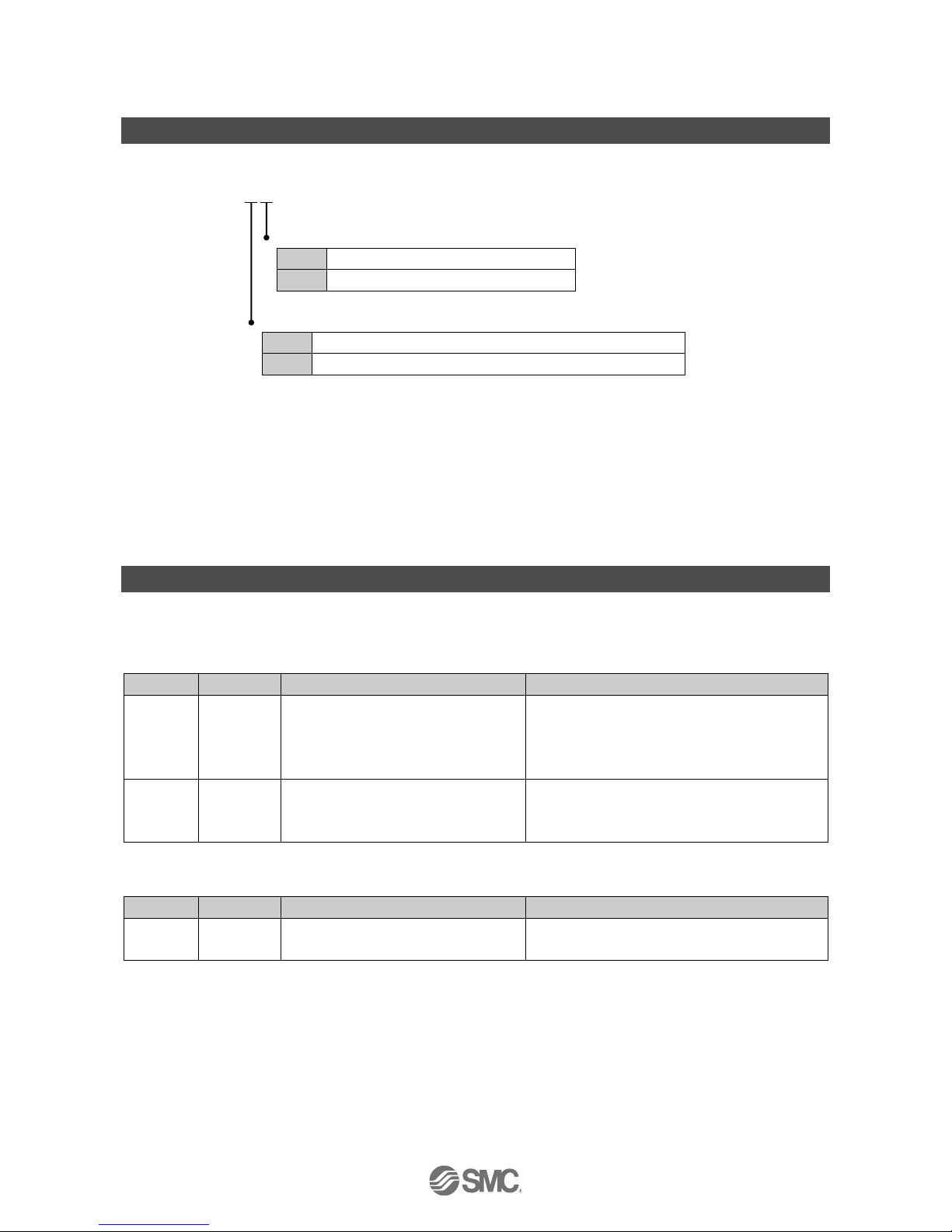
Model Indication and How to Order
•Output block
EX9-OE
Output type
1
Source / PNP (negative common)
2
Sink / NPN (positive common)
Power supply type
T
Internal power supply from SI unit (for low wattage load)
P
External power supply type (for high wattage load)
: A Power block is required.
•Power block
EX9-PE1
Product Outline
The EX9 series is connected between an applicable SI unit and the valve manifold to operate equipment such
as a solenoid valve or relay. An Output block and Power block are available.
•Output block
Type
Part No.
Description
Remarks
For low
wattage
load
EX9-OET1
EX9-OET2
Current Output to connected load
(output equipment) or manifold valves
using the power supply from the SI unit.
Usable load wattage is limited to 1.5 W because
power is supplied by the SI unit.
When the load is up to 12 W, use both the Power
block and a high wattage load Output block.
For high
wattage
load
EX9-OEP1
EX9-OEP2
Current Output to connected load
(output equipment) using an external
power supply.
For use with the Power block (EX9-PE1) which
uses an external power supply.
: Limited to 1.0 W when the EX500-Q02 SI unit (page 54) is connected.
•Power block
Type
Part No.
Description
Remarks
-
EX9-PE1
Provides an external power supply to
the Output block for high wattage load.
For use with the Output block for high wattage
load.
-9-
No.EX※※-OMH0025-C
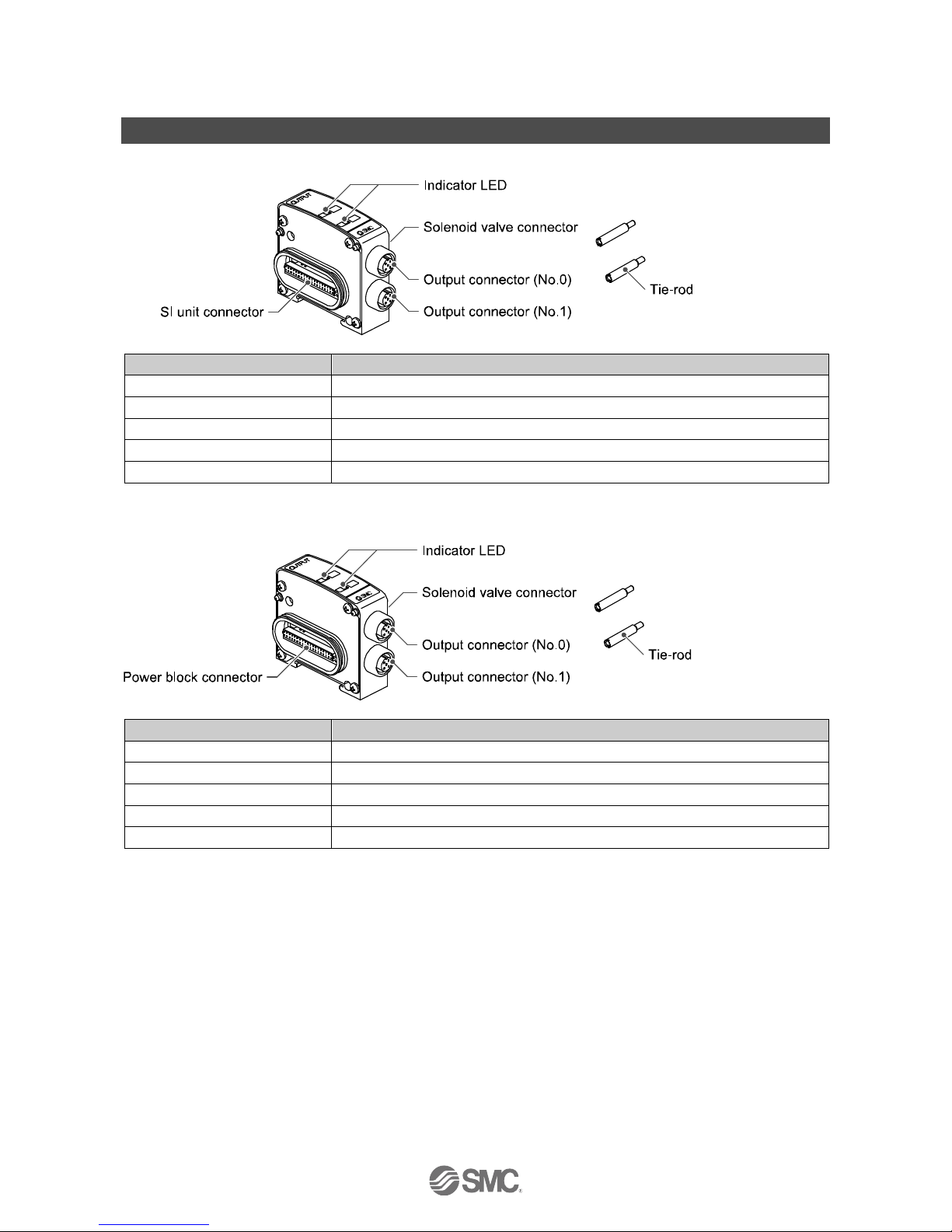
Summary of Product elements
EX9-OET1, EX9-OET2 (Output block for low wattage load)
Element
Function
Indicator LED
Indicates the output status.
Solenoid valve connector
Connected to solenoid valve.
Output connector (No.0)
Connects with output device.
Output connector (No.1)
Connects with output device.
SI unit connector
Connected to SI unit.
EX9-OEP1, EX9-OEP2 (Output block for high wattage load)
Element
Function
Indicator LED
Indicates the output status.
Solenoid valve connector
Connected to solenoid valve.
Output connector (No.0)
Connects with output device.
Output connector (No.1)
Connects with output device.
Power block connector
Connected to Power block.
-10-
No.EX※※-OMH0025-C
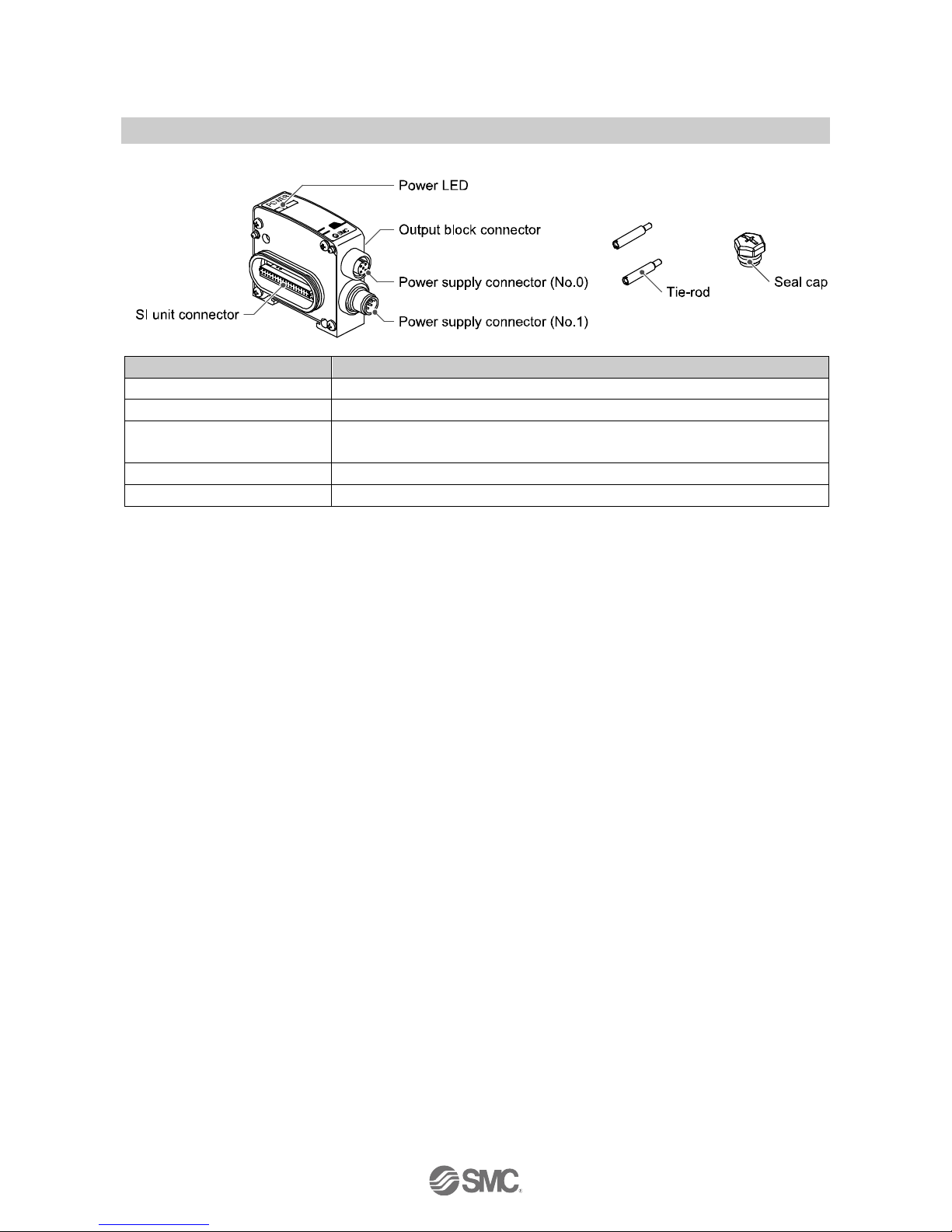
2. EX9-PE1 (Power block)
Element
Function
Power LED
Indicates the power supply status.
Output block connector
Connected to Output block for high wattage load.
Power supply connector (No.0)
Connector to supply power to the SI unit, only when the SI unit (EX250 or EX500
series) is on the left side of the EX9-PE1 (Power block).
Power supply connector (No.1)
Connector to supply power to the Output block for high wattage load.
SI unit connector
Connected to SI unit.
: Refer to page 39.
-11-
No.EX※※-OMH0025-C
Product Selection
■Selection for low wattage and high wattage load
The type is selected based on the SI unit type and the current consumption of the connect load.
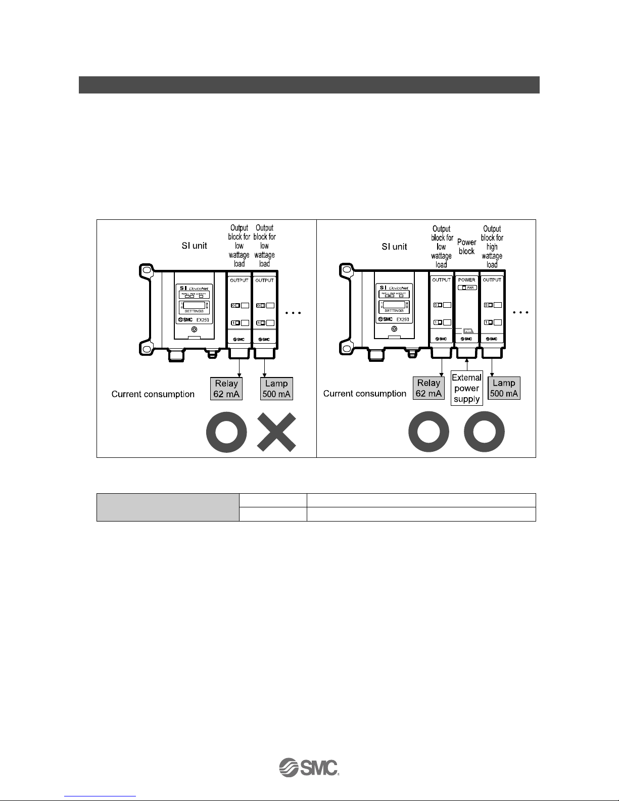
•EX126 and EX250 series (excluding the one power supply system for AS-i)
The Output block for low wattage load should not be used when the current consumption of the connected
output equipment (load) is above the rated current of 62 mA (1.5 W, 24 VDC).
If used, the SI unit will malfunction.
The Output block for high wattage load and a Power block must be used when the current consumption
exceeds the rated load current of 62 mA.
[Example]
○: This is possible to use it.
×: This is not possible to use it.
Current consumption of the load
(output equipment)
62 mA or less
Use Output block for low wattage load
Above 62 mA
Use Output block for high wattage load + Power block
-12-
No.EX※※-OMH0025-C
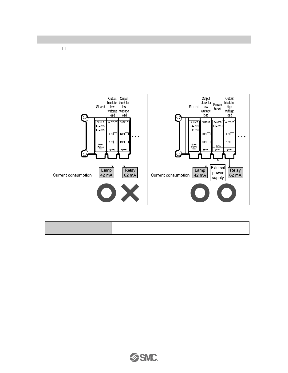
•EX500-Q
02 (page 54)
The Output block for low wattage load should not be used when the current consumption of the connected
output equipment (load) is above the rated current of 42 mA
(1.0 W, 24 VDC).
If used, the SI unit will malfunction.
The Output block for high wattage load and a Power block must be used when the current consumption
exceeds the rated load current of 42 mA.
[Example]
○: This is possible to use it.
×: This is not possible to use it.
Current consumption of the load
(output equipment)
42 mA or less
Use Output block for low wattage load
Over 42 mA
Use Output block for high wattage load + Power block
-13-
No.EX※※-OMH0025-C
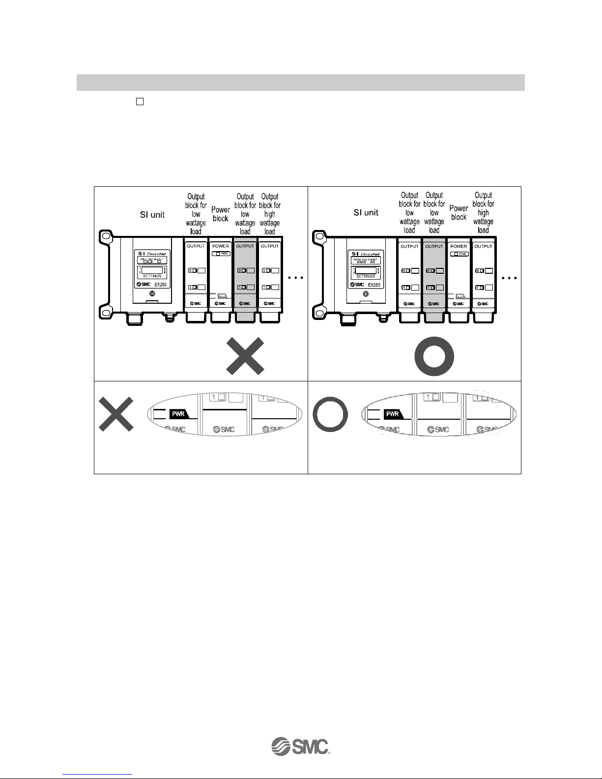
■EX9-OET
(Output block for low wattage load)
•Location
The Output block for low wattage load cannot be placed closer to the valve manifold than the Power block.
If the Output block for low wattage load is positioned like this, it will not operate.
The correct position is with the Output block for low wattage load located between the SI unit and the
Power block.
[Example]
: There is no continuous line on the product
labels. (Incorrect positioning)
: There is a continuous line on the product
labels. (Correct positioning)
○: This is possible to use it.
×: This is not possible to use it.
-14-
No.EX※※-OMH0025-C
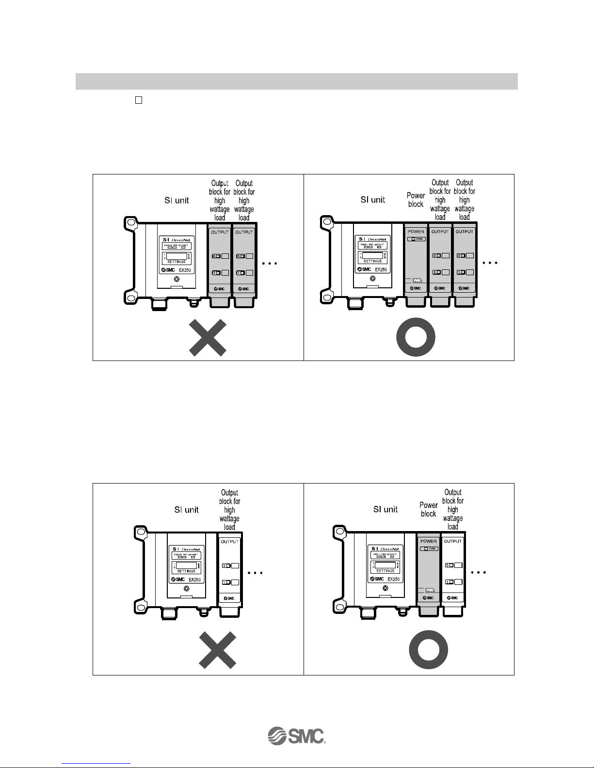
■EX9-OEP
(Output block for high wattage load)
•Combination
The Output block for high wattage load (EX9-OEP) cannot be used independently.
If the Output block for high wattage load is used independently, it will not operate.
It must be used together with a Power block (EX9-PE1).
[Example]
○: This is possible to use it.
×: This is not possible to use it.
•Location
The SI unit or Output block for low wattage load cannot be positioned to the left of the Output block for high
wattage load.
If the Output block for high wattage load is positioned like this, it will not operate.
Place the Power block closer to the SI unit than the Output block for high wattage load.
[Example]
○: This is possible to use it.
×: This is not possible to use it.
-15-
No.EX※※-OMH0025-C
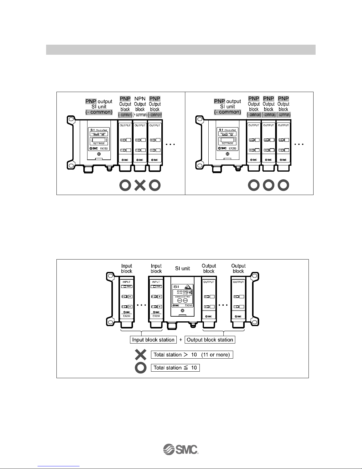
■Polarity
Be sure to use an Output block with a polarity consistent with the polarity (output style) of the SI unit.
If a product with the incorrect polarity is connected, the Output block will not operate.
[Example]
○: This is possible to use it.
×: This is not possible to use it.
■The number of connected stations
The maximum number of connected stations in total of input / Output blocks (excluding SI unit) is 10.
If more than 10 stations are connected, damage can result due to a lack of strength.
[Example]
○: This is possible to use it.
×: This is not possible to use it.
-16-
No.EX※※-OMH0025-C
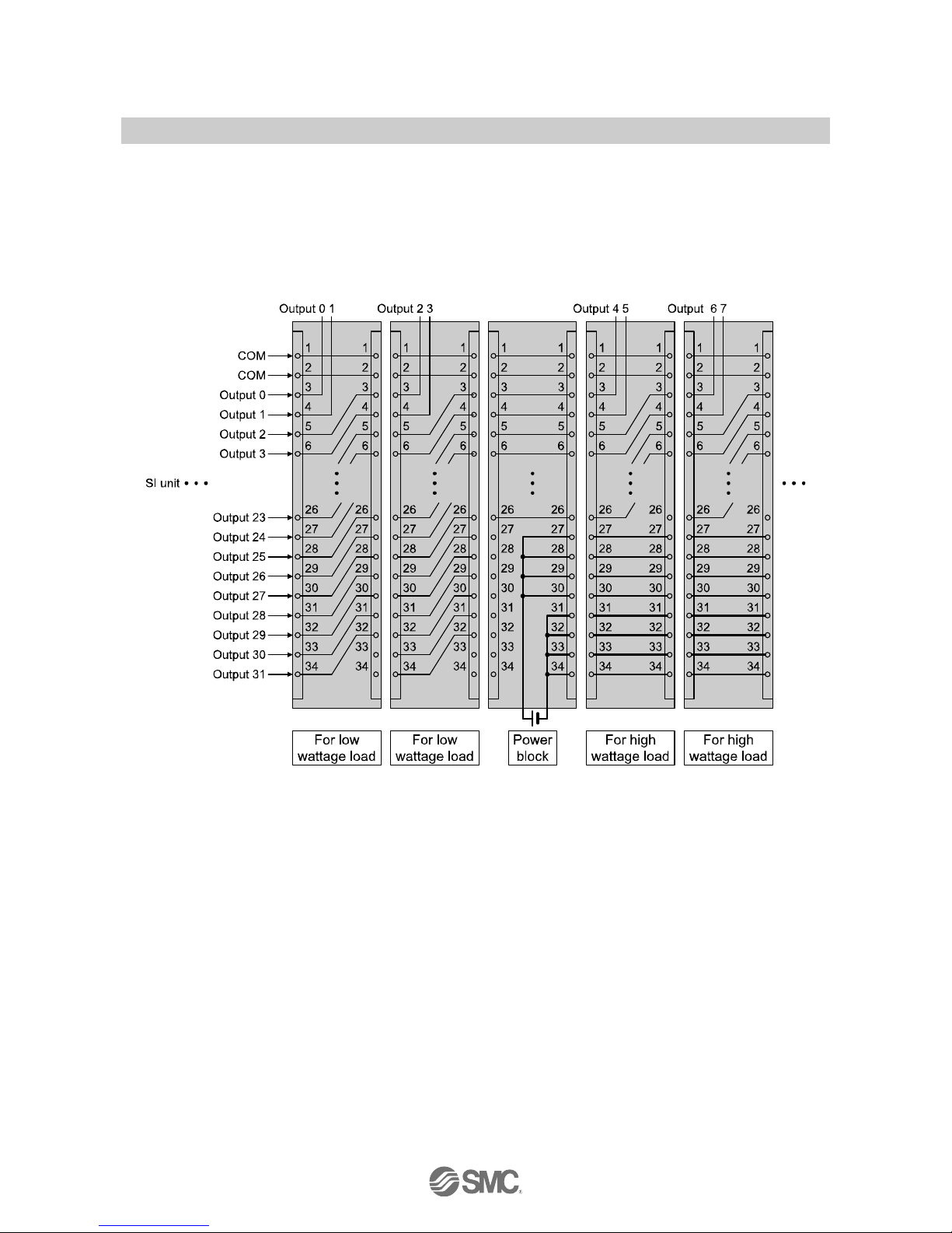
■Limit of output points when the Output block for high wattage load and Power block are used
•EX250-SDN1, -SMJ2, -SPR1, -SCA1A, -SEN1
The maximum output points of the Output block for low wattage load is 32 (for connector pin No. 3 to 34)
When an Output block for high wattage load and Power block are used, the number of output points of the
Output block (on the right of the Power block) is limited to 24 points (connector pin No. 3 to 26). This is
because 8 points (connector pin No.27 to 34) are used to output the power supply from the Power block to
the Output block for high wattage load (32 points - 8 points =24 points).
-17-
No.EX※※-OMH0025-C
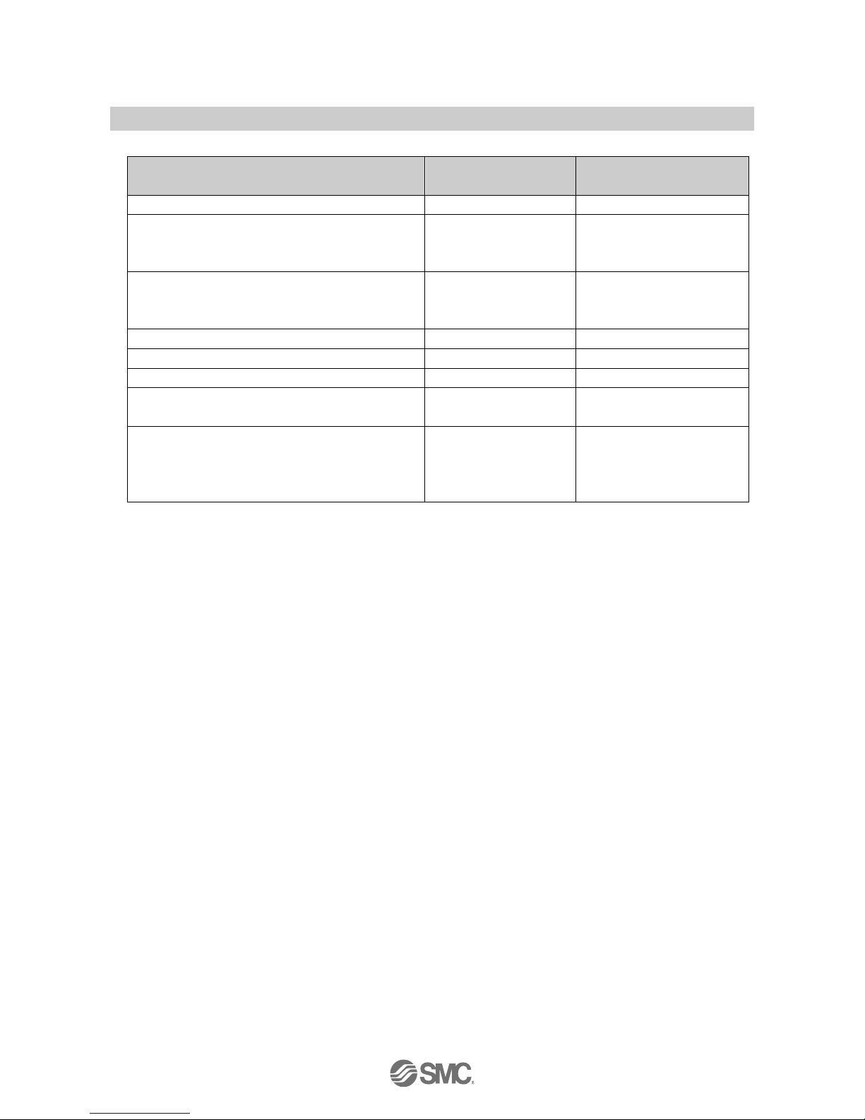
Table: Maximum number of output points when the Power block is used
SI unit model No.
SI unit specification
Max. number of output points
when the Power block is used
EX250-SDN1, -SMJ2, -SPR1, -SCA1A, -SEN1
32 inputs / 32 outputs
24 points
EX260-SDN1, -SDN2, -SMJ1, -SMJ2, -SPR1, -SPR2
EX260-SPR5, -SPR6, -SEN1, -SEN2, -SEC1, -SEC2
EX260-SPN1, -SPN2, -SPL1
32 outputs
24 points
EX260-SDN3, -SDN4, -SMJ3, -SMJ4, -SPR3, -SPR4
EX260-SPR7, -SPR8, -SEN3, -SEN4, -SEC3, -SEC4
EX260-SPN3, -SPN4, -SPL3
16 outputs
16 points
EX126D-SMJ1
16 outputs
16 points
EX250-SAS5, -SAS9
4 inputs / 4 outputs
4 points
EX250-SAS3, -SAS7
8 inputs / 8 outputs
8 points
EX500-Q002, -Q102
Gateway branch system
16 outputs
16 points
EX500-S103
Gateway branch system 2
16/32 outputs
(Selected using built-in
setting switch)
16 outputs
(with setting of 16 outputs)
24 outputs
(with setting of 32 outputs)
: If the Output block is used with the EX250 series, it can be connected to the product with manufacturing lot GV (Aug. 2002) or later.
Terminal block plate (VVQC1000-74A-2) which is shipped after March 2004 can be connected to EX126 for adding the Output block.
These products and assemblies have the body to enable connection with the Output block.
 Loading...