

Page 1
No.EX※※-OMV0017-B
PRODUCT NAME
I/O Configurator (NFC version)
MODEL / Series / Product Number
EX600-WEN# (Wireless master)
EX600-WPN# (Wireless master)
EX600-WSV# (Wireless slave)
Page 2

-1-
No.EX※※-OMV0017-B
Contents
1. Introduction 3
1.1. Definition and terminology 5
2. Preparation before use 7
2.1. Software Installation 7
2.2. Before starting the software 8
2.3. Download the I/O Configurator (NFC version) 9
2.4. Start the I/O Configurator 10
3. Window of I/O Configurator (NFC version) 11
3.1. Basic characteristics 11
3.1.1. Login to administrator mode 13
3.2. Display for wireless master 14
3.2.1. Information tab 14
3.2.2. Input/Output monitor tab 16
3.2.3. Setting tab 20
3.3. Display for wireless slave 30
3.3.1. Information tab 30
3.3.2. Input/Output monitor tab 32
3.3.3. Setting tab 36
3.4. Detailed information of units 40
3.4.1. Information tab 40
3.4.2. Details of I/O monitor tab 49
4. Setting Function 56
4.1. Edit TAG 56
4.2. Software Control 56
4.3. Forced output 58
4.3.1. Forced output conditions 58
4.3.2. Forced output procedure 59
4.3.3. Forced output release procedure 62
4.4. Export Settings 63
4.5. Import Settings 65
4.6. Reading of the initial value 66
4.7. Initialize 67
Page 3

-2-
No.EX※※-OMV0017-B
5. Pairing of wireless unit 69
5.1. Pairing procedure of wireless unit 69
5.2. Registration of dummy slave 74
6. Wireless system configuration example 75
6.1. Flow chart for using the wireless system (Refer to Step 2) 75
6.2. System Construction Example 76
6.3. Preparation 78
6.4. (1) Input and output size of the wireless slave 82
6.5. (2) Set the number of occupied I/O points for the module and
each parameter of the "wireless master" 92
6.6. (3) Set the "wireless master" system 96
6.7. (7) Ethernet setting for the wireless master 99
6.8. (4) Registration of wireless slave to the wireless master (pairing) 102
6.9. Download the configuration file 114
7. Wireless system parameter list 116
8. Error Codes 119
9. Troubleshooting 120
10. Release Notes 122
Page 4
-3-
No.EX※※-OMV0017-B
1. Introduction
This operation manual describes the installation, construction of screens and operation method of the I/O
configurator for NFC. The SMC wireless system I/O Configurator for NFC can be used to check the parameter
setting of the wireless unit and the contents and status of the constructed wireless system, using an NFC
reader/writer and a PC.
There are two types of settable parameters with the I/O Configurator: the parameters which can be read or
written when no power is supplied to the product and the parameters which can be read or written only
when the power is supplied to the product.
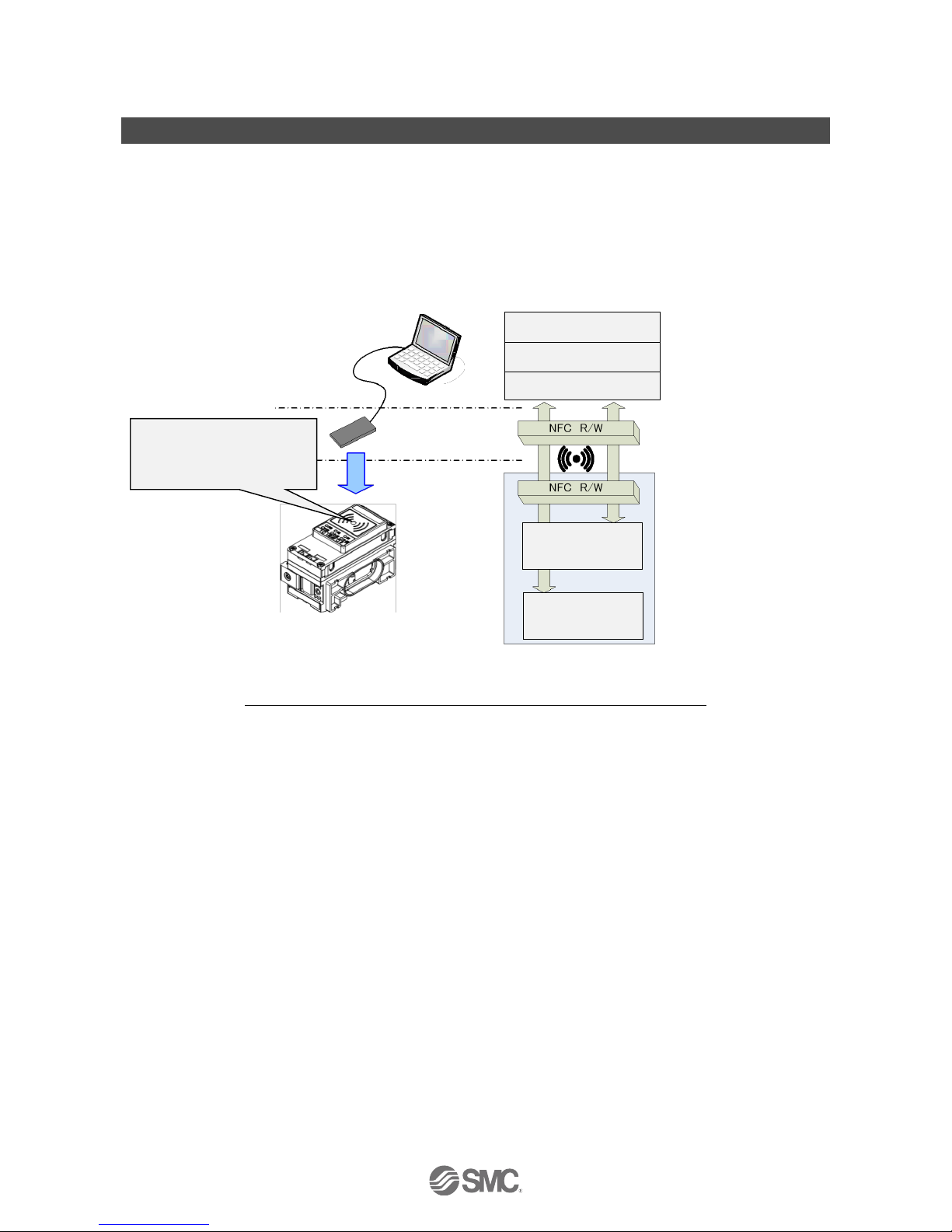
The connection details of the I/O Configurator for NFC and the wireless unit is shown in the below figure.
※One PC will recognize one NFC reader / writer per application setting.
Do not connect multiple NFC readers / writers to a PC.
Connection details of the I/O Configurator for NFC and the wireless unit
Before the wireless system can be used, it is necessary to pair each slave with its master using the
I/O configurator for NFC.
The following sections of this document should be read before using the I/O configurator for NFC;
2. Preparation before use (page 7), which describes installation of drivers and the I/O configurator software
3.1.1. Login as administrator (page 13)
5. Pairing of wireless unit (page 69)
6. Wireless system configuration example (page 75)
PC
NFC reader/writer
Wireless master unit
Wireless slave unit
I/O Configurator
OS (Windows)
PC/SC driver
Memory area where
power supply is
unnecessary.
Memory area where
power supply is
necessary.
Establish communication by
adjusting the position so that the
height from the center of the
NFCR/W antenna to the "O" on the
wireless unit is 1 cm or less.
※
Page 5

-4-
No.EX※※-OMV0017-B
: About the communication timing
The NFC communication is not accessed all the time. Therefore, it is necessary to update the contents displayed on
the screen by clicking the "Refresh button" when reading the parameters. The parameters changed are valid after
re-supplying the power supply or by pressing the reset button in the I/O Configurator screen. As the parameter
setting requires time for settlement, do not turn off the power supply for 2 seconds.
: Establishing communication after changing units
As the settings between the wireless master unit and the wireless slave unit are different, it is necessary to update the
displayed parameter by clicking the "Refresh button" on the screen of the I/O Configurator for NFC after changing the
unit in which the parameter is set.
: Operation already checked. NFC reader/writer
SONY Corporation
RC-S380/S
Advanced Card Systems Ltd.
ACR1251U (FW212 or later), ACR1252U (FW104.6 or later)
: I/O Configurator (Web version)
This operation manual explains the outline of the setting using the I/O Configurator (NFC). I/O Configurator (Web) is
used to set the module I/O occupied points and parameters for the "wireless master" and parameters for the "I/O
devices". Refer to the operation manual for the I/O Configurator (Web version).
: The product is available in Japanese, English, and Chinese by setting the language in the Windows OS.
Page 6

-5-
No.EX※※-OMV0017-B
1.1. Definition and terminology
Term
Definition
A
Administrator mode
Administrator mode allows the user to configure the wireless units.
B
Broken line detection
A broken wire to the input or output equipment has been detected by the diagnostic
function.
D
DHCP
A protocol that automatically allocates information, necessary to be registered to use
the network, such as an IP address, to individual devices connected to the TCP/IP
network.
Dummy slave
A Dummy slave can be used to reserve a dummy area within the I/O map. A wireless
slave can then be registered to the dummy area at a later time, without having to
change the I/O map
E
Export
Function to save the configured values of a wireless unit by exporting them to a PC.
F
Fieldbus
Network protocol to establish digital communication between an automated industrial
system such as a measurement tool or manipulation tool and a PLC.
Full duplex
Communication system that can send and receive data at the same time
bi-directionally.
H
Half-duplex
Communication method that can send and receive data reciprocally in bi-directional
communication.
I
Import
Function to reconfigure a wireless unit by importing values stored on a PC.
I/O Configurator
(NFC version)
Application used to directly set and monitor the wireless unit parameters via an NFC
reader/writer.
I/O Map
Memory area reserved for the I/O data and diagnostic information of the wireless system
IP address
A 32 bit digit sequence which is assigned to identify devices which are connected to the
network.
M
MAC address
A unique number inherent to all devices connected to an Ethernet network.
Manifold
Aggregate.
Module
A Module consists of a wireless master or a wireless slave combined with I/O units and
a valve manifold.
Monitor mode
Monitor mode allows the user to monitor the configuration of the wireless units but not
make setting changes.
N
NFC
Abbreviation of Near Field Communication. A Non-contact short distance wireless
communication used for configuration of the Wireless units
Number of outputs
Number of points which can operate output equipment such as a valve, lamp or motor
starter.
Page 7

-6-
No.EX※※-OMV0017-B
Term
Definition
O
Occupied points for
the module
input/output
Number of I/O points that can be controlled by a module.
P
Paring
Registration of the PID (Product ID) of the wireless slave unit to be connected to the
wireless master unit. Registration occurs at the initial setting, then wireless system will
activate.
PID
Abbreviation of Product ID. A 32 bit digit sequence which is assigned to identify the
wireless unit (master/slave unit).
PLC
Abbreviation of Programmable Logic Controller. A digital computer used for automation
of electromechanical processes.
S
Short circuit detection
Diagnostic function which detects generation of over current due to a short circuit
between the output and the positive power supply line or the ground line.
Short circuit
protection
Function which avoids damage to the internal circuit when over current is generated
due to short circuit between the output and the positive power supply line or the ground
line.
R
Refresh button
Button to display the latest configuration of the wireless units, as set by the I/O
configurator for NFC.
Reset button
Button to update the wireless units with the latest configuration set by the I/O
configurator for NFC. Note: Restarting the wireless unit will also activate the latest
configuration.
W
Wireless channel
Identification number of the wireless slave unit connected to the wireless master unit.
Wireless master
A unit which establishes wireless communication of input or output data to the wireless
slave. It is connected to a PLC to establish communication of input or output data.
Wireless slave
A unit which establishes wireless communication of input or output data to the wireless
master.
Wireless unit
A unit which establishes wireless communication. This is a generic name of the wireless
master and slave units.
Page 8

-7-
No.EX※※-OMV0017-B
2. Preparation before use
2.1. Software Installation
Driver: The following drivers should be installed before using this software.
When the SONY Corporation RC-S380/S NFC reader is used
(1): Microsoft. Net Framework 4.0 or higher
http://www.microsoft.com/en-US/download/details.aspx?id=17718
(2): NFC reader, writer connection driver NFC port software
(Ver 5.5.0.6 / Approx.39 MB / Apr.24.2017)
https://www.sony.net/Products/felica/business/products/RC-S380.html
When the Advanced Card Systems Ltd. ACR1251U/ACR1252U NFC reader is used.
(1): PC/SC Driver
(Ver 4.2.8.0 / 2018.3.20)
https://www.acs.com.hk/en/products/342/acr1252u-usb-nfc-reader-iii-nfc-forum-certified-reader/
When the NFC reader / writer is held over the product, an error message may appear, such as “Device driver
software was not successfully installed” or “Smart card was not identified” depending on the version of
Windows OS. The reader / writer can be continuously used.
Refer to the Microsoft website (http://support.microsoft.com/kb/976832/).
Page 9
-8-
No.EX※※-OMV0017-B
2.2. Before starting the software
When the SONY Corporation RC-S380 NFC reader is used, set up the NFC port following the procedure
below. When the Advanced Card Systems Ltd. ACR1251U/ACR1252U NFC reader is used, the following
setting procedure is not necessary.
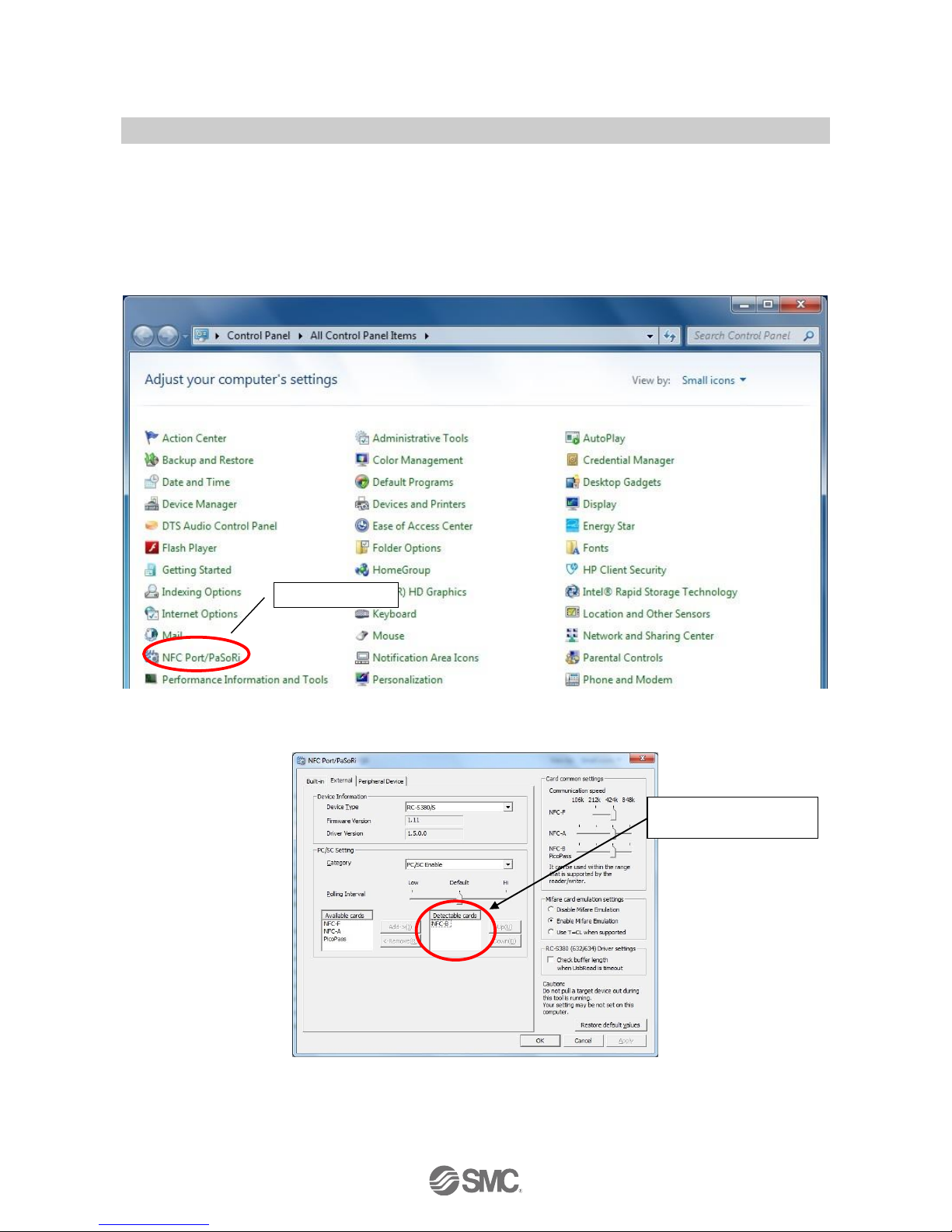
(1) The NFC setting on the control panel of your PC must be changed as follows.
Setting: Operate the NFC-B preferentially using the protocol used.
(Windows7 is used in this Operation Manual)
(2) Double-click the [NFC port/PaSoRi] icon on the control panel to display the setting window.
(Windows7 is used in this Operation Manual)
(3) When the setting window is displayed, move [NFC-F], [NFC-A] and [PicoPass] from the card information
indicated on the [Detectable cards] to the [Available cards] selection box using the "Delete" button.
Select the icon.
Select [NFC-B] only for
[Detectable cards].
Page 10
-9-
No.EX※※-OMV0017-B
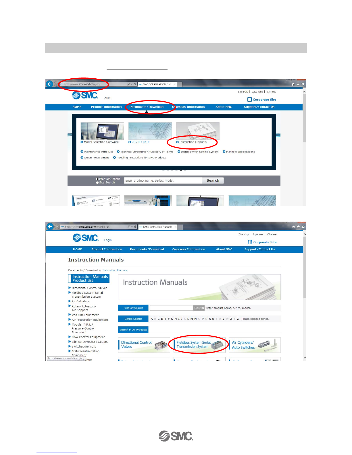
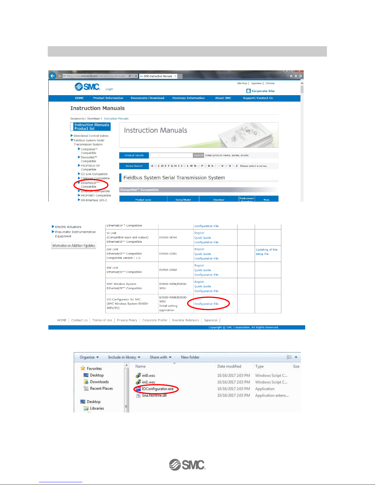
2.3. Download the I/O Configurator (NFC version)
(1) On the SMC website (http://www.smcworld.com), select the Documents/Download and select the
Instruction Manuals.
(2) Select the Fieldbus System Serial Transmission System.
Page 11
-10-
No.EX※※-OMV0017-B
(3) Select the protocol that the product supports. (Example: EtherNet/IP™ compatible)
(4) Scroll down the page of the Fieldbus System Serial Transmission System and select the Configuration File
of I/O configurator for NFC. Downloading will begin.
2.4. Start the I/O Configurator (NFC version)
Open the downloaded file and double click the IO Configurator.exe to start the I/O configurator for NFC. If the
IOConfigurator.exe is moved to the desk top, move the folder of the configurator or create the short cut of the
I/O configurator.exe for further use.
Page 12
-11-
No.EX※※-OMV0017-B
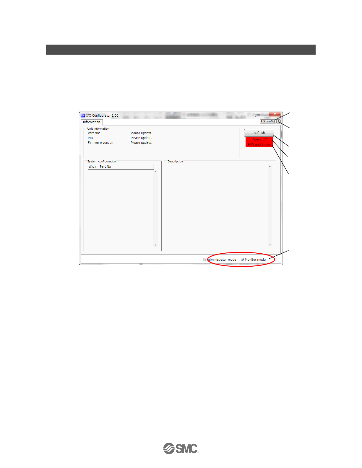
3. Window of I/O Configurator (NFC version)
In this chapter, the screen display in I/O Configurator (NFC version) in Wireless Master/Slave will be explained.
3.1. Basic characteristics
The window below is displayed when the I/O configurator for NFC starts. Place the NFC reader/writer within 1
cm of the centre of the wireless symbol on the wireless unit to display the wireless master/slave information
and change the parameter setting.
Here, basic functions of the I/O configurator for NFC are given.
(1)
(2)
(3)
(4)
(5)
(6)
Page 13
-12-
No.EX※※-OMV0017-B
•Basic characteristics
No.
Item
Explanation
1
NFC setting button
When the SONY Corporation RC-S380/S NFC reader is used.
When the NFC setting button is clicked, "NFC port/PaSoRi" is displayed on the setting
screen. (Refer to 2.2 Before starting the software. (page 8))
2
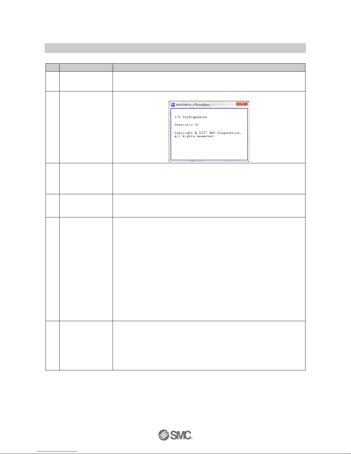
Question mark
The I/O configurator for NFC software version appears by clicking the question mark.
3
Refresh button
The Refresh button updates the information displayed on the application window.
The information on the window is not updated unless the button is clicked. Always click
this button when moving the tab or after parameter setting.
The Refresh button is displayed on all screens.
4
Power supply
ON/OFF button
LED display to indicate the wireless unit power supply status. Power ON is displayed
when power for the wireless master/slave is supplied. Power OFF is displayed when
power is not supplied.
5
R/W detection/
R/W no-detection
button
Indicates the connection status of the PC-NFC reader/writer.
When the SONY Corporation RC-S380/S NFC reader is used.
No driver:
NFC reader/writer driver is not installed.
Refer to Preparation before use (2. Preparation before use
(page 7)).
R/W undetected:
NFC reader/writer driver is installed. NFC reader/ writer is not
identified or USB is not connected.
R/W detected:
NFC communication with the wireless unit is available.
When the Advanced Card Systems Ltd. ACR1251U/ACR1252U is used.
No driver:
NFC reader/writer is not identified or USB is not connected.
※ This is displayed when the Advanced Card Systems Ltd.
driver software is installed.
R/W detected:
NFC communication with the wireless unit is available.
6
Monitor mode/
Administrator mode
These radio buttons switch the mode between Monitor mode and Administrator mode
(button on the lower right of the I/O configurator for NFC window).
Monitor mode: Wireless unit information or I/O map and parameter setting can be read.
Parameters cannot be set. Forced output function cannot be used.
Administrator mode: All functions are available after confirming the password is valid.
: The mode is automatically changed to monitor mode unless a mouse operation is
performed within 300 seconds in Administrator mode.
Page 14
-13-
No.EX※※-OMV0017-B
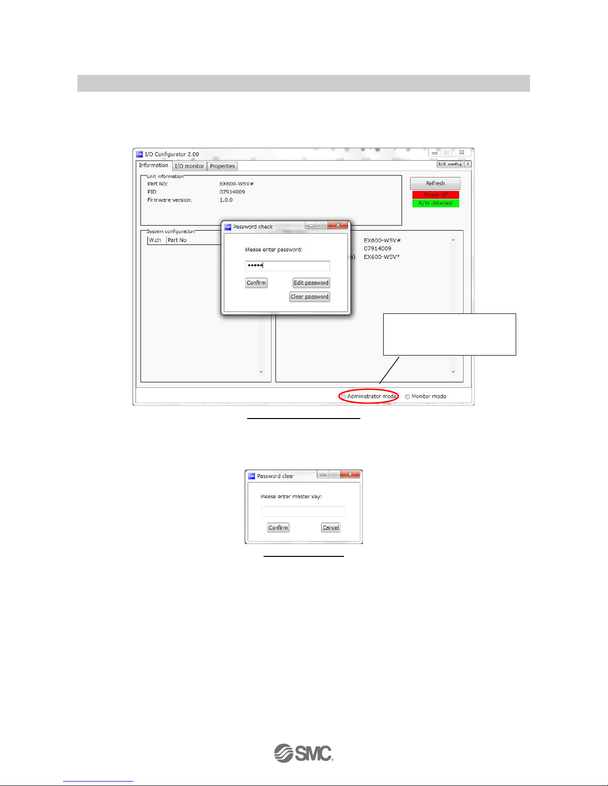
3.1.1. Login to administrator mode
Password is necessary to login to the Administrator mode. The Initial password is "admin". In administrator
mode It is possible to change the password using "Edit password".
For security, change the password for the first time of access.
Default password: admin
If the password is forgotten, the previously set password can be deleted using "Clear password". When the
[Clear password] button is clicked, the password clear window will appear. By entering the master key
(ADMIN) in the password box, the password is cleared and the next step can be accessed without password.
Master key: ADMIN
Password check window will
open by clicking the
Administrator mode.
Page 15

-14-
No.EX※※-OMV0017-B
3.2. Display for wireless master
The tabs available on the upper left of the I/O configurator for NFC consists of the Information (page 14), I/O
monitor (page 16) and Properties (page 20).
3.2.1. Information tab
The Information tab consists of (A) Unit information, (B) System Configuration and (C) Description.
(A) Unit information
The Unit information area indicates the unit information.
•Module information
Description
Content
NFC access
Energized
Not energized
Part No.
Wireless unit product number
Available
Available
PID
Wireless master unit PID
Available
Available
Firmware version
Displays software version of the wireless master unit.
Available
Available
MAC address
MAC address of the wireless master unit
Available
Available
IP address
IP address of the wireless master unit
Available
Not available
Subnet mask
Subnet mask of wireless master unit
Available
Not available
Module input/output size
Number of occupied points for the control input and output of
the wireless master unit.
Available
Not available
Online/All slaves
Indicates the number of online slaves/registered slaves.
Available
Not available
System I/O size
Number of Input and output points in the wireless system
Available
Not available
(A)
(B)
(C)
Page 16
-15-
No.EX※※-OMV0017-B
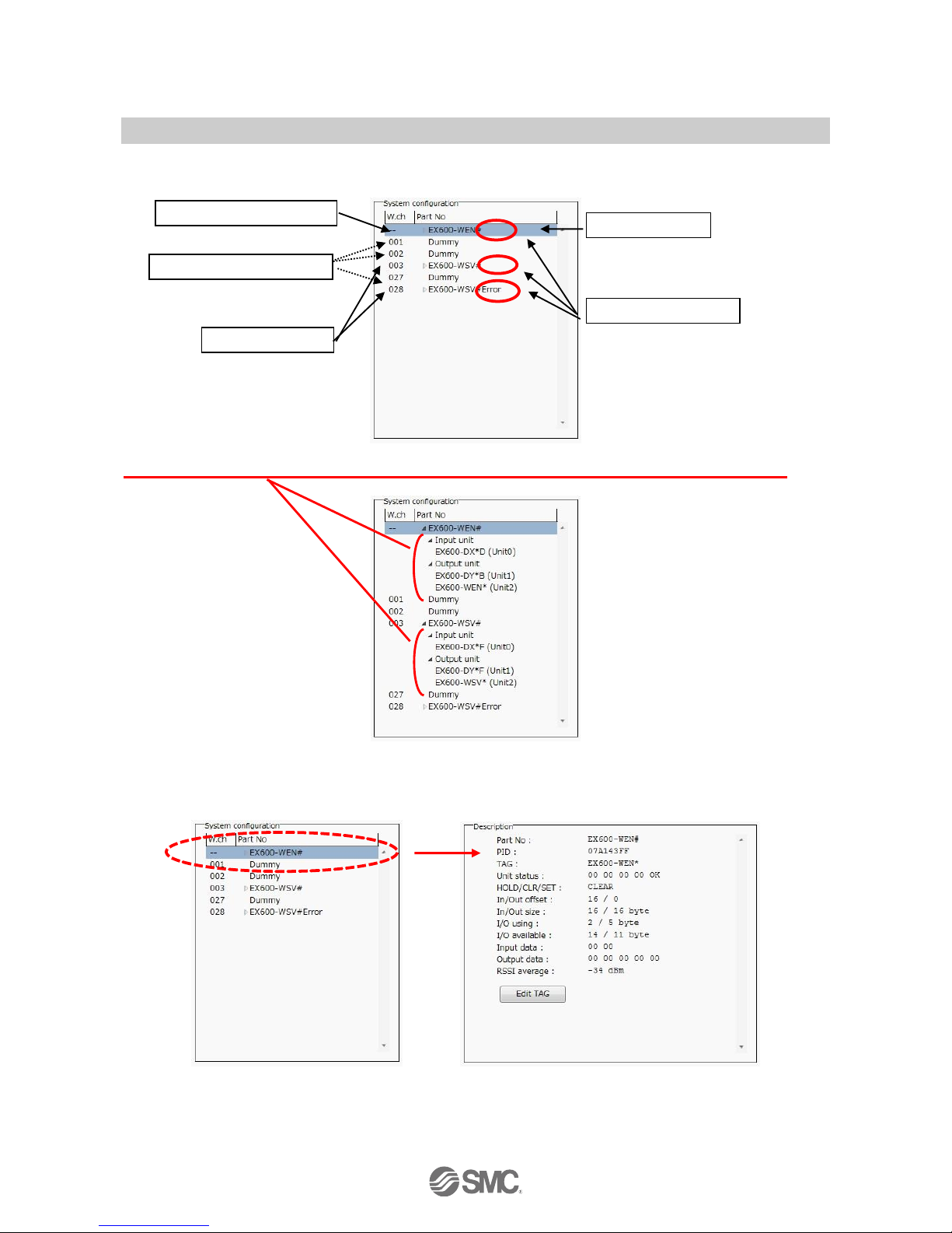
(B)System Configuration
System configuration shows the configuration information of the wireless master/slave module.
In System configuration, connected I/O units can be checked by clicking on the displayed wireless unit.
(C) Description
Description about the unit selected in the System configuration. The Description is displayed by clicking on
the wireless unit or I/O unit in the System configuration.
: Description varies depending on the unit type. Refer to 3.4 Detailed information of units (page 40) for details.
Dummy slave (reserved)
Wireless master unit
Wireless slave
Error is indicated
Unit selection
Page 17
-16-
No.EX※※-OMV0017-B
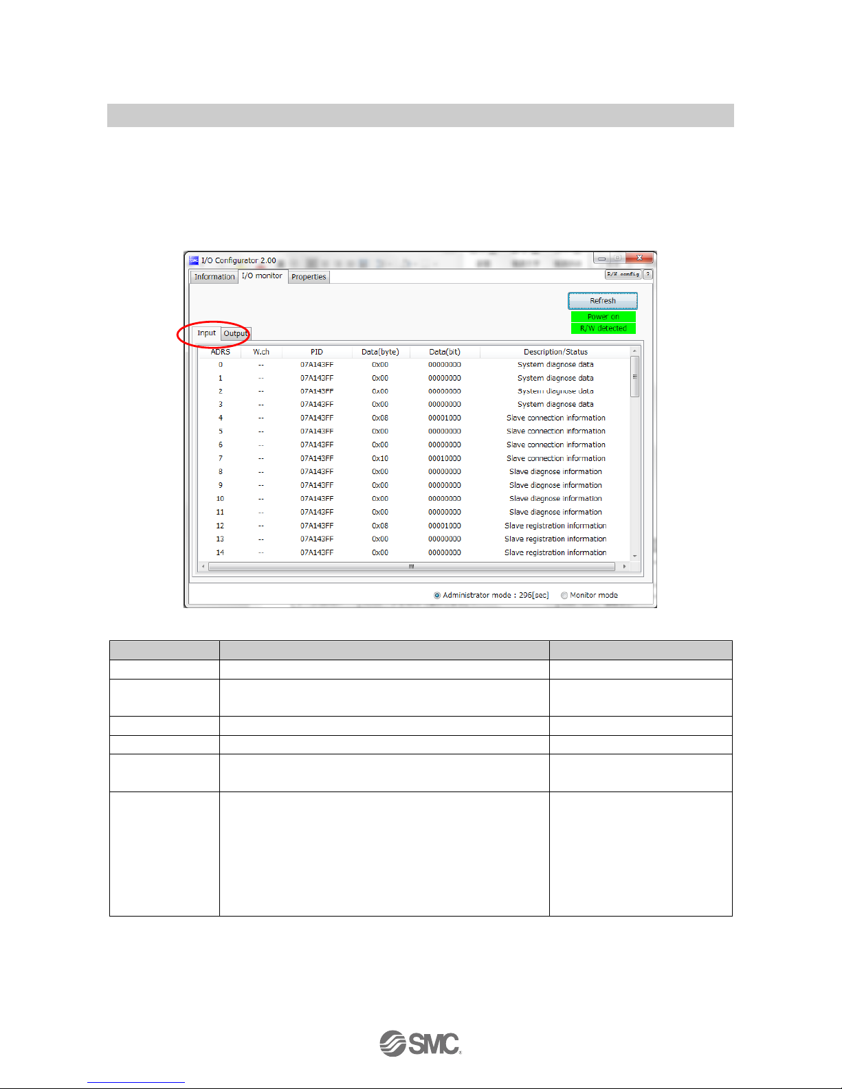
3.2.2. Input/Output monitor tab
In the I/O monitor tab, the wireless unit I/O map data can be monitored. Diagnosis information or details of
input/output can be checked by double clicking each line in the display.
Forced output mode (4.3 Forced output (page 58)) can be selected within the Output tab.
3.2.2.1. Input tab
Input tab shows the input map information of the wireless unit.
•Input display
Display
Content
Displayed items
Address
Displays the input map address.
0 to 159
Wireless CH
Wireless unit channel.
(Wireless channel of the wireless master is displayed as [- -].)
--, ch001 to 127
PID
Wireless unit PID
Individual per unit.
Data (byte)
Input data is displayed in byte.
0x00 to 0xFF, no information
Data (bit)
Input data is displayed in bit.
00000000 to 11111111, no
information
Details
Details of inpu data.
•System diagnosis data
•Slave connection information
•Slave diagnostic information
•Slave registration information
•Master input
•Slave input
•Reserve input
•Connection error
Page 18
-17-
No.EX※※-OMV0017-B
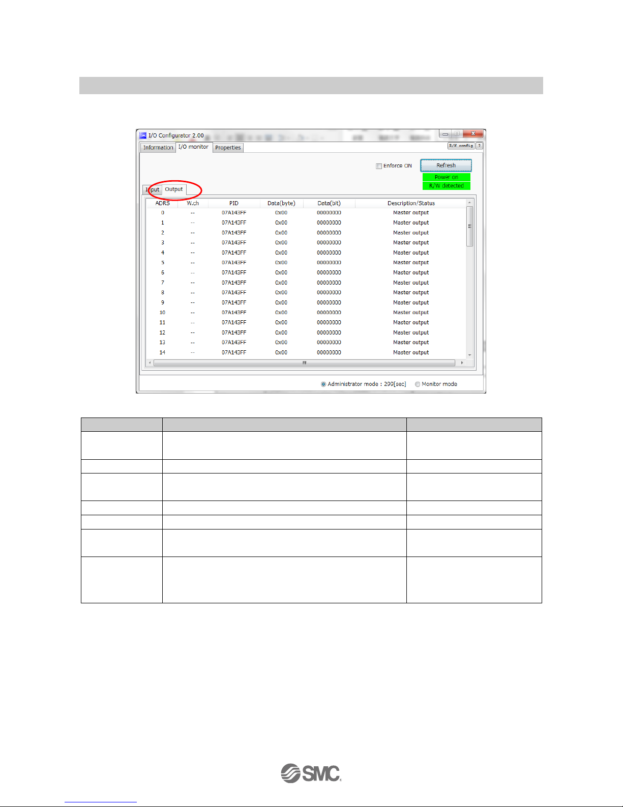
3.2.2.2. Output tab
Output tab shows the output map information of the wireless unit.
•Output display
Description
Content
Displayed items
Enforce ON
Forced output mode can be selected by clicking Enforce ON.
: Refer to 4.3 Forced output (page 58) for the operation.
Checked : Enforce ON
Unchecked : Enforce OFF
Address
Displays the input map address.
0 to 159
Wireless CH
Wireless unit channel.
(Wireless channel of the wireless master is displayed as [- -].)
--, ch001 to 127
PID
Wireless unit PID
Individual per unit.
Data (byte)
Output data is displayed in byte.
0x00 to 0xFF, no information
Data (bit)
Output data is displayed in bit.
00000000 to 11111111, no
information
Details
Details of output data.
•Master output
•Slave output
•Reserve output
•Connection error
Page 19
-18-
No.EX※※-OMV0017-B
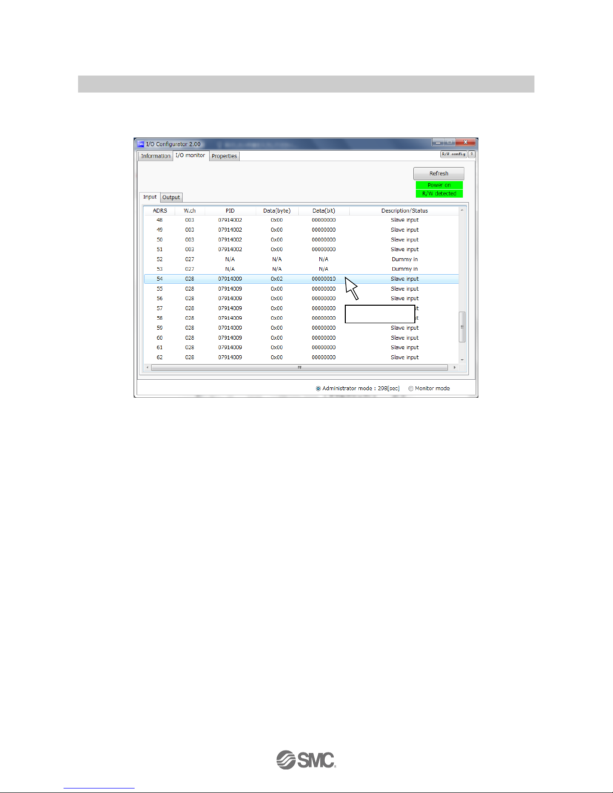
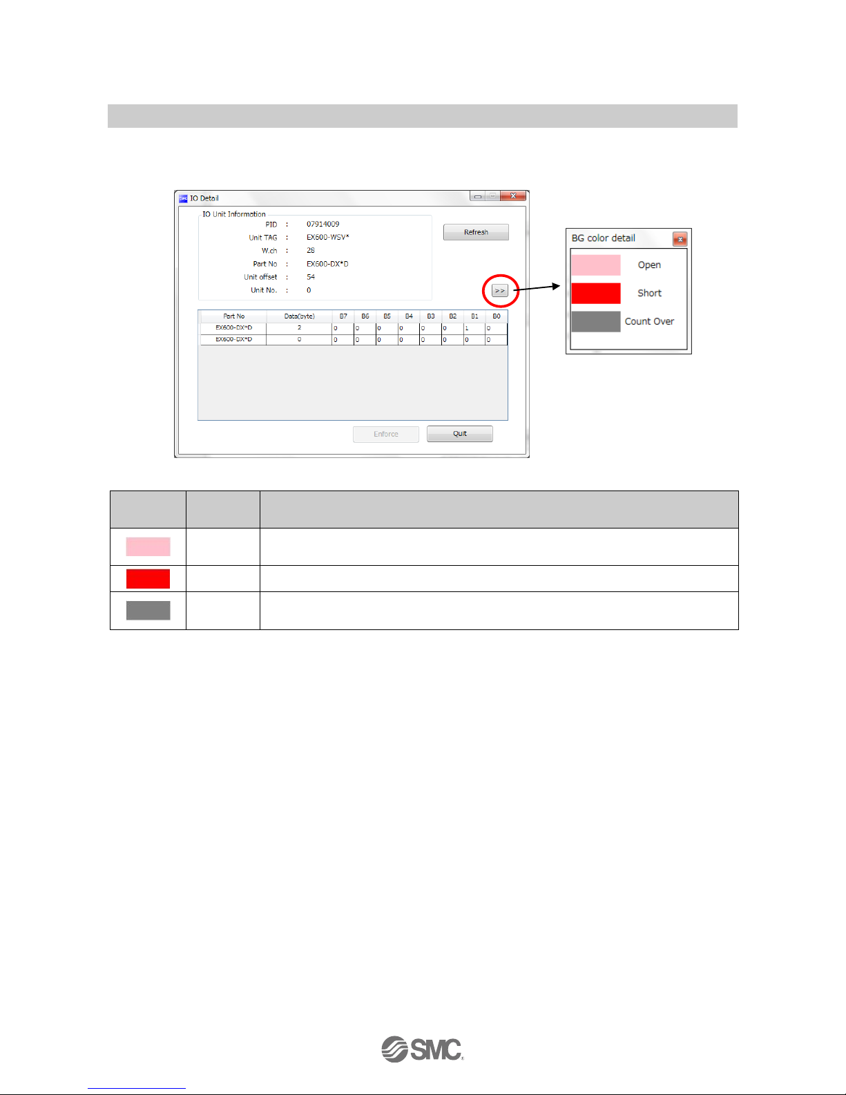
3.2.2.3. I/O Detail
I/O Detail will open by double clicking the line of the desired address of I/O unit which is connected to the
wireless unit.
Double-click
Page 20
-19-
No.EX※※-OMV0017-B
IO unit information, IO data & diagnostics can all be checked in the IO Detail window. Diagnostic error type is
represented by different background colours. The meaning of background colour can be checked by clicking
[>>].
•Background colour
Background
colour
Error
Description
Open
Detection of unconnected load
: Invalid in initial state. Enable the function from the I/O configurator (WEB version).
Short
Short circuit detection
Count Over
Contact frequency upper limit detection
: Invalid in initial state. Enable the function from the I/O configurator (WEB version).
: Description varies depending on the unit type. Refer to 3.4 Detailed information of units (page 40) for details.
Page 21
-20-
No.EX※※-OMV0017-B
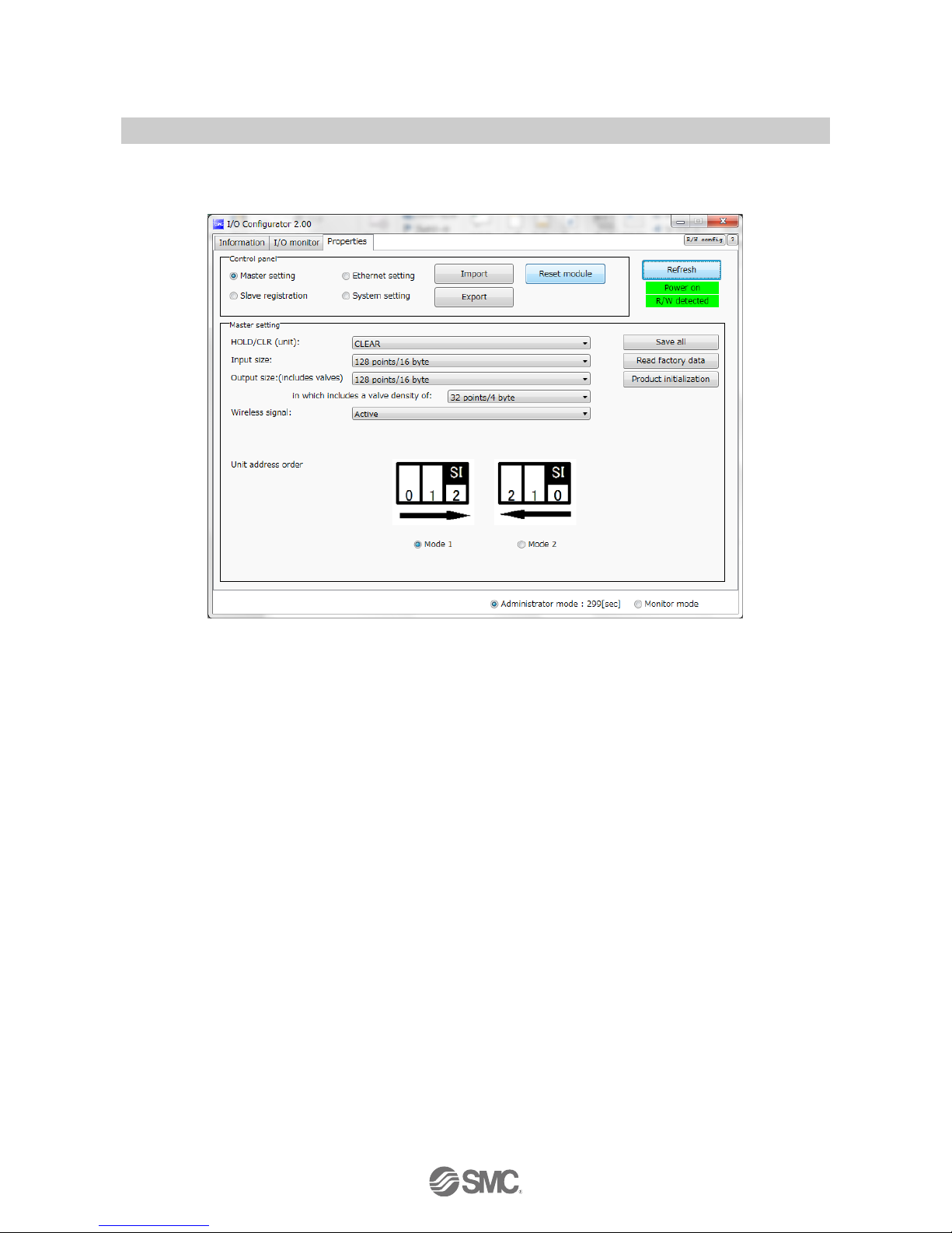
3.2.3. Setting tab
The configuration of the connected unit can be changed using the setting tab. It consists of setting items
(page 21) and the setting display (page 22) (Master setting, Ethernet setting, Slave registration and System
setting).
Setting display
Set item
Page 22
-21-
No.EX※※-OMV0017-B
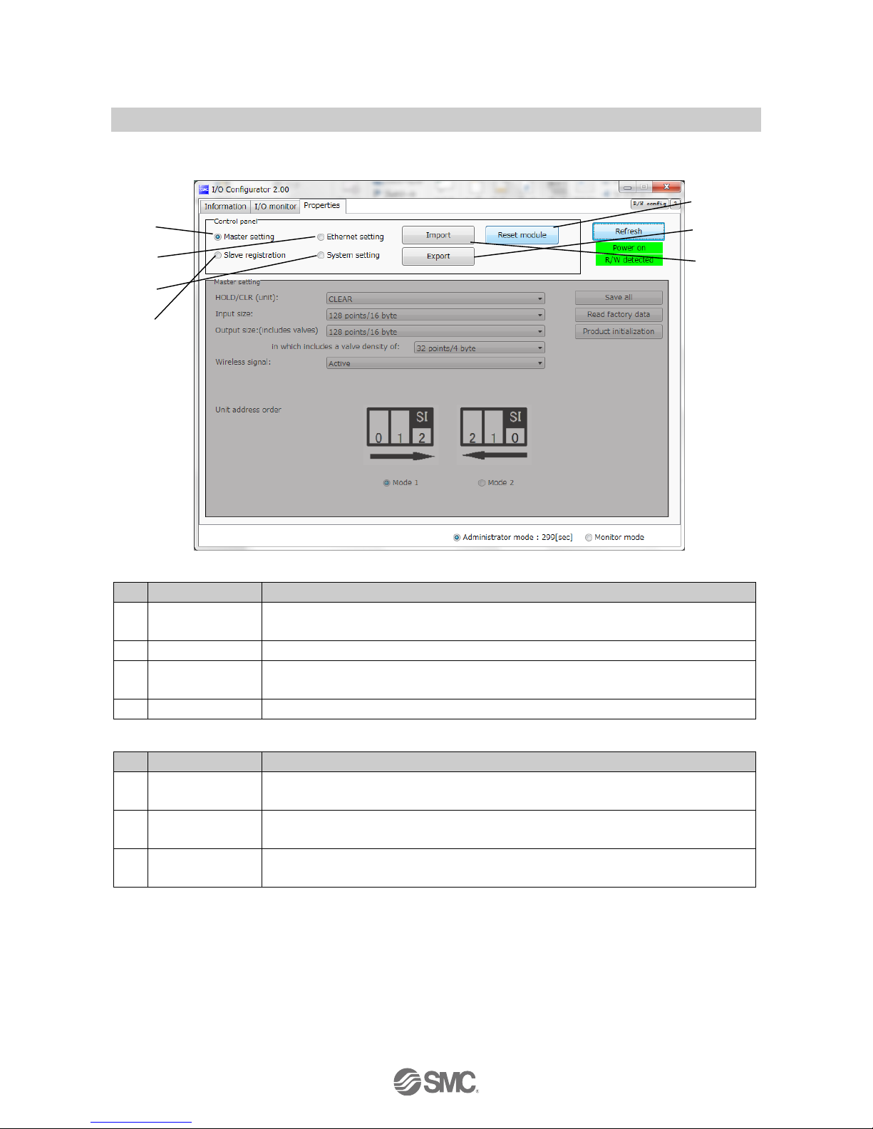
3.2.3.1. Setting items
Control panel for setting consists of 4 radio buttons and 3 buttons.
•Radio buttons for selecting the required setting window.
No.
Description
Function
A
Master setting
Switch to the master unit setting window. Occupied points for the module input/output can
be set.
B
Ethernet setting
Switch to Ethernet setting window. Performing the IP address setting.
C
Slave registration
Switch to the slave unit registration window. Wireless slave or dummy slave can be
registered in the wireless master.
D
System setting
Switch to system setting display. The number of system input/output points can be set.
•Buttons for Setting
No.
Description
Functions
1
Reset module
Set parameters are returned to the time of power supply to the wireless unit. Click Reset
module in order to reflect the parameter setting while power is supplied.
2
Export
Button to export the configuration of the wireless unit to a PC (saved as file type ".smc").
Refer to 4.4. Export Settings (page 63).
3
Import
Button to import the saved configuration of the wireless unit from a PC (imported from file
type ".smc"). Refer to 4.5. Import Settings (page 65).
: When the Reset module button is used, the wireless unit restarts and Ethernet communication or wireless communication is
temporarily interrupted.
(2)
(3)
(1)
(A)
(B)
(C)
(D)
Page 23
-22-
No.EX※※-OMV0017-B
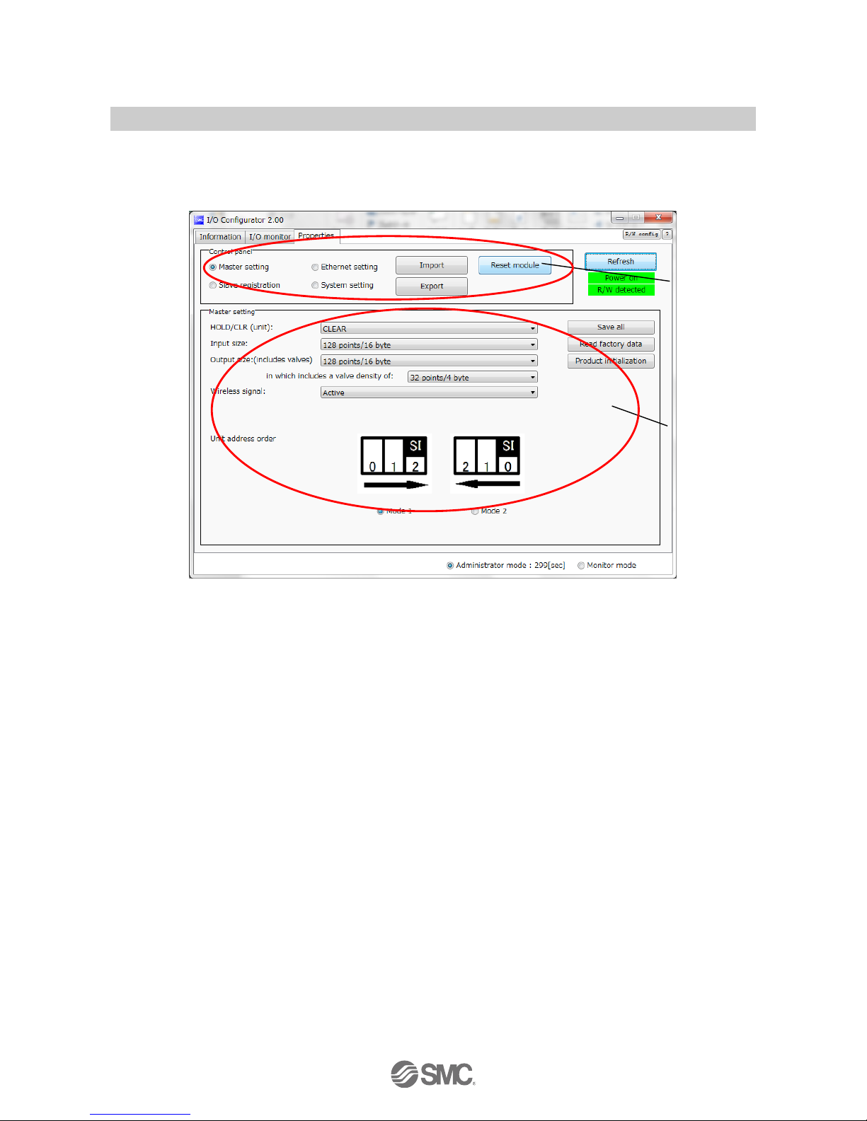
3.2.3.2. Setting display
(A) Master unit setting
The Master unit setting window.
Page 24
-23-
No.EX※※-OMV0017-B
•Master unit setting items
Description
Explanation
Hold/Clear (unit)
Define all settings in the output operation status when the Fieldbus communication is
disconnected.
CLEAR: Clear the output.
HOLD: Fix the output at the current value.
Software control: Clear, Hold or Set for individual points can be set by software bit.
: For details of the Software Control. (Refer to 4.2 Software Control (page 56) for setting in
I/O configurator for NFC)
Occupied points for
the module input
Set the number of inputs which can be controlled by the wireless master unit.
Setting range: 0 to 128 points (0 to 16 bytes). Increase or decrease by 16 points.
Occupied points for
the module output
Set the number of outputs which can be controlled by the wireless master unit.
Setting range: 0 to 128 points (0 to 16 bytes). Increase or decrease by 16 points.
The module output point includes the number of points of the valve manifold output.
Occupied points for
the valve manifold
output
Set the number of outputs to be allocated to the valve manifold output from the number of
points set in the module output size.
As the valve manifold output point is included in the module output point, the number of
effective points are limited within the setting range of the module output point.
Setting range: 0 to 32 points (0 to 4 bytes). Increase or decrease by 8 points.
Wireless
communication
Define the operation status of wireless communication.
: Wireless communication is updated in real time. Turning off and on again of the power
supply or reset is not necessary.
Active: Wireless communication is available.
Idle: Disconnect the wireless communication.
I/O unit assignment
direction
Define the address assignment direction of the EX600 I/O units connected to the wireless
master unit.
The address assignment direction is changed by mode 1/mode 2. Be careful about the I/O
map.
(Refer to the I/O Mapping Order of Wireless Master/Slave Module of the Operation Manual
(page 50) for details)
Mode 1: Assignment to the right from the end plate.
Mode 2: Assignment to the left from the wireless unit.
•Master unit setting button
No.
Description
Functions
1
Save
Changed setting is stored in the equipment. Perform reset to reflect the setting.
2
Reading of the
initial value
Button to read the default value of the window being displayed.
Refer to 4.6. Reading of the initial value (page 66) for use.
3
Initialize
Initialize the unit to the default condition. Refer to 4.7. Initialize (page 67) for use.
Page 25
-24-
No.EX※※-OMV0017-B
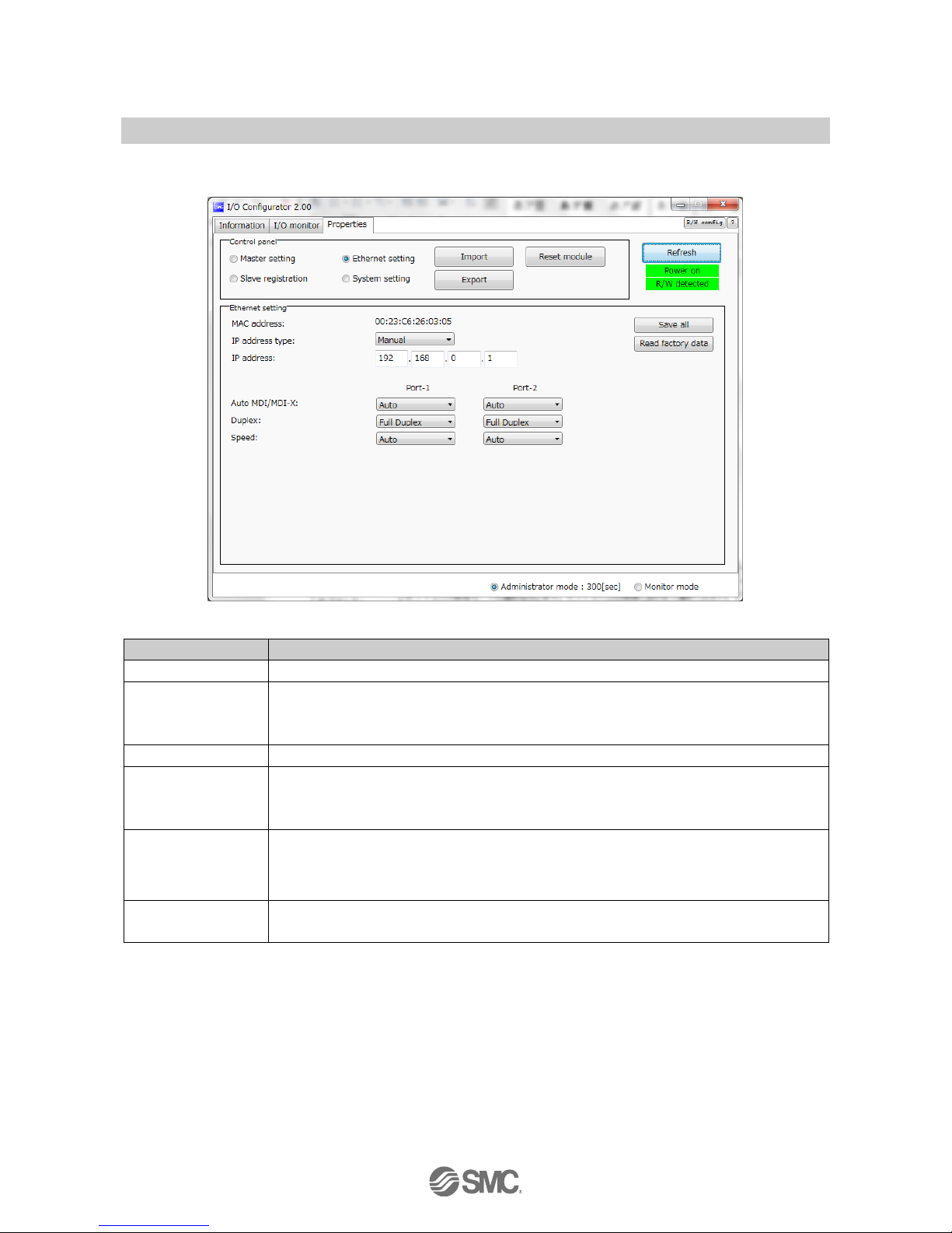
(B) Ethernet setting
Ethernet setting display.
•Ethernet setting items.
Description
Explanation
MAC address
MAC address of the product is displayed.
IP address setting
mode
Select the IP address setting mode. Select the mode suitable for your network environment.
Manual: The IP address is set by inputing it directly.
BOOTP/DHCP: The IP address is set automatically via the DHCP server.
IP address
Sets the IP address. (The IP address is valid only when "Manual" mode is selected.)
Auto MDI/MDI-X
Select settings for straight cable or crossed cable. Select the settings suitable for your
environment.
Setting range: Auto/MDIX/MDI
Duplex
Set Duplex. Select the communication speed suitable for your environment. When the
communication speed is set to automatic mode, it is set automatically regardless of the
Duplex setting.
Setting range: Full Duplex/Half Duplex
Speed
Set the communication speed. Select the communication speed suitable for your environment.
Setting range: Auto/100 Mbps/10 Mbps
Page 26
-25-
No.EX※※-OMV0017-B
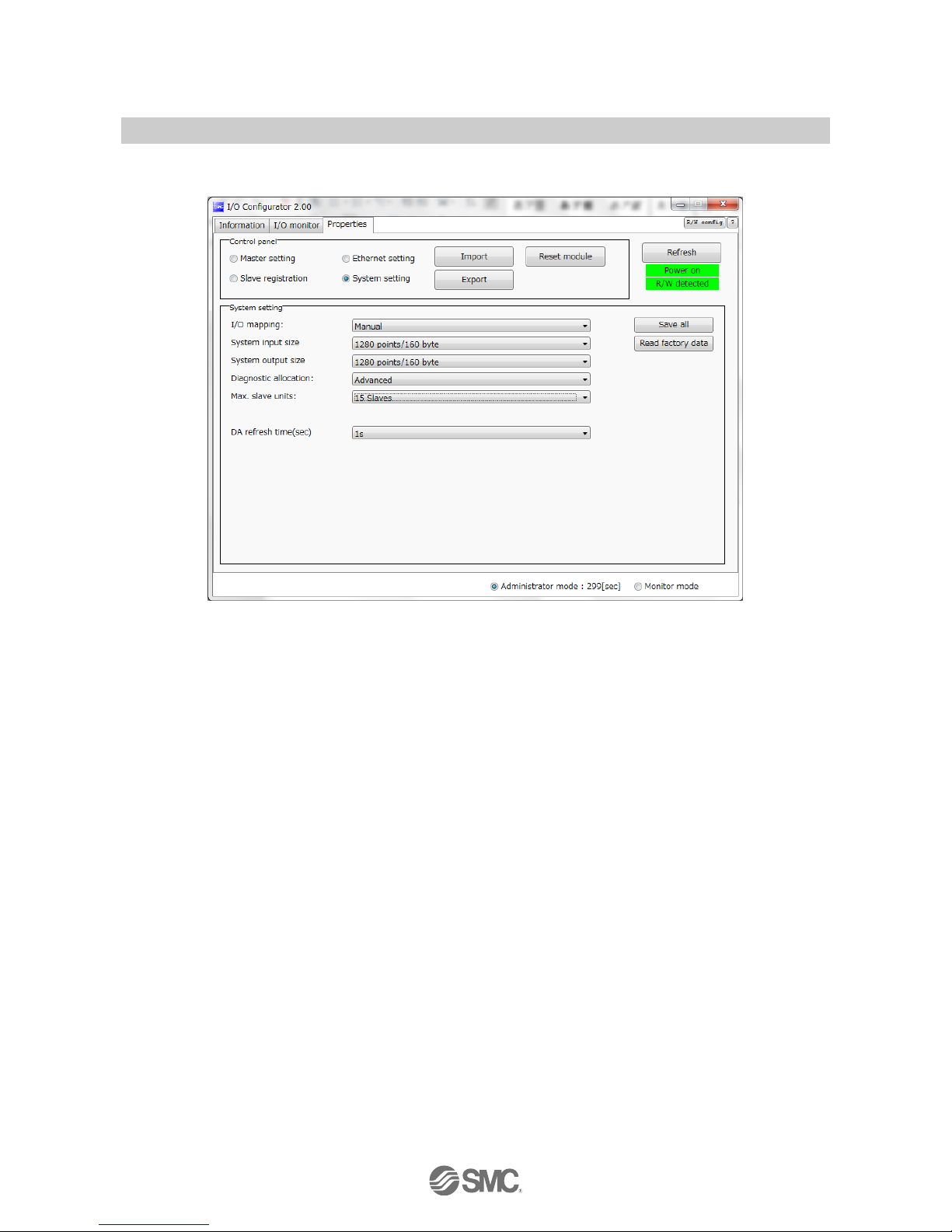
(C) System setting
System setting display.
Page 27
-26-
No.EX※※-OMV0017-B
•System setting items
Description
Explanation
I/O layout
Define the I/O assignment of the entire wireless system including the wireless slave unit
registered to the wireless master unit.
Auto assignment: All I/O points mapped to the wireless master unit and wireless slave
unit are identified and mapped automatically.
(The total number of connected I/O points is the total number of I/O
points set by the diagnostic information, wireless master and registered
slave unit.)
Fixed assignment: Fixed at the number of I/O points set in the System input size and
System output size.
※”Auto assignment” is fixed for EX600-WPN※
System input size
Set the number of inputs which can be controlled by the entire wireless system.
Setting range: 16, 128 to 1280 points (2 to 160 bytes). Increase or decrease by 128 points.
: Number can only be set when Fixed mapping is used for IO mapping.
System output size
Set the number of outputs which can be controlled by the entire wireless system.
Setting range: 16, 128 to 1280 points (2 to 160 bytes). Increase or decrease by 128 points.
: Number can only be set when Fixed mapping is used for IO mapping.
Diagnostic allocation
Set the diagnostic information allocated to the I/O map. Refer to the "Diagnostic allocation"
section in the Operation Manual (page 56) for details.
None: No diagnostic data
Simple: System diagnosis
Detailed: System diagnosis + Wireless slave connection/diagnosis/registration information
Number of registered
slave
Set the number of wireless slave units which are registered to the wireless master unit.
Wireless channels for the number of the set units are valid.
Setting range
EX600-WEN# : 0/15/31/63/127 pcs.
EX600-WPN# : 0/15/31 pcs.
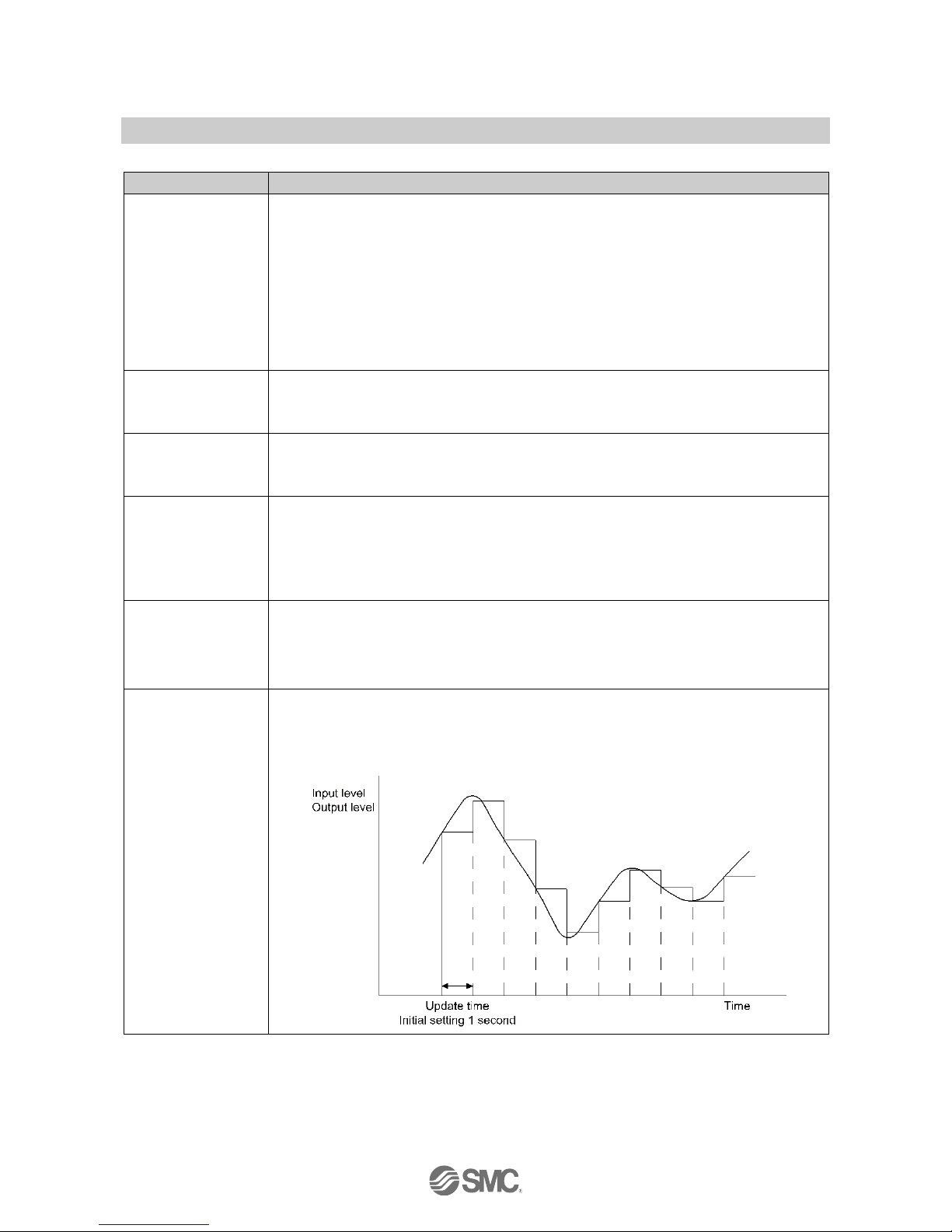
Analogue output
update time
Set the data update time of the analogue output unit connected to the wireless slave.
Setting range: 0.1/0.2/0.5/1/2/5/10/30/60 s (Initial value 1 s)
: The analogue input update time can also be set for every wireless slave unit. Refer to "(A) Slave unit
setting" (page 38).
Page 28
-27-
No.EX※※-OMV0017-B
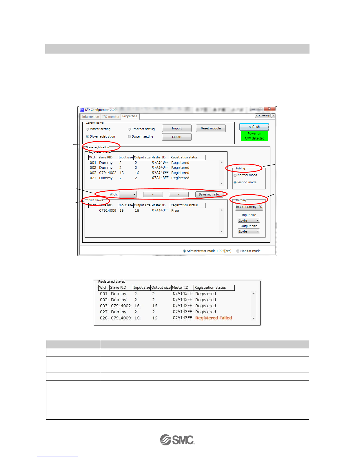
(D) Slave unit registration
Registration for wireless communication between the wireless master unit and the wireless slave unit.
For this wireless system, it is necessary to register the PID for each product to establish communication
without interference from another network. The window for Slave registration consists of Registered slaves,
Save reg. info., Free slaves, Pairing and Dummy.
: Registration of slaves needs to be performed with the power supplied. Refer to 5. Pairing of wireless unit (Page 69) for the registration
procedure.
(1) Registered slave
Details of the registered slave.
•Details of the registered slave
Description
Content
Wireless channel
Wireless master channel used when the wireless slave was registered.
Slave PID
Wireless slave PID
Input size
Wireless slave input size
Output size
Wireless slave output size
Master PID
PID of the registered wireless master
Registration status
Current registration status
(Registered information is saved "Registered", registered information is not saved
Registered Wait, registration is not successful Registered Failed)
: When the registration is not successful, "Registered Failed" is displayed. Start the registration again.
(1)
(2)
(3)
(4)
(5)
Page 29
-28-
No.EX※※-OMV0017-B
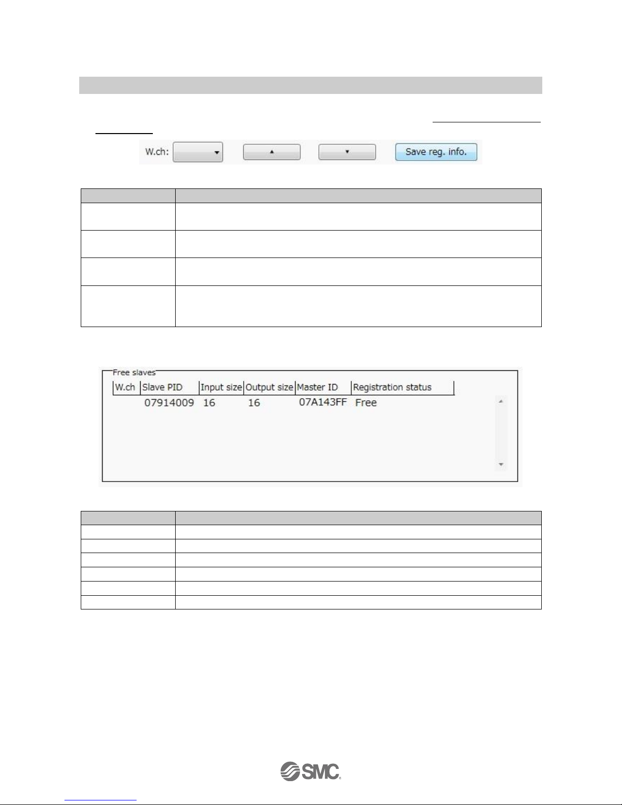
(2) Save registration buttons
Buttons used for slave registration. Slave registration buttons are only displayed when wireless units are in
pairing mode.
•Slave registration buttons
Description
Content
Wireless channel
Select the channel used to register the slave to the wireless master.
(Only channels available for registration will be displayed)
[▲]
Button to move the wireless slave from Free slaves to Registered slaves.
(Specify the wireless channel before moving)
[▼]
Button to move the wireless slave from Registered slaves to Free slaves
(The wireless slave will now be displayed in the Free slaves area)
Save the registered
information "Save reg.
info".
Button to register the slaves shown in “Registered slaves” with the status “Registered Wait”
("Registered" will be displayed when the slave is successfully registered to the wireless
master)
(3) Free slaves
Details of the Free slaves.
•Details of Free slave
Description
Content
Wireless channel
No information to display
Slave PID
Wireless slave PID
Input size
Wireless slave input size
Output size
Wireless slave output size
Master PID
Previously registered master PID.
Registration status
Display the status "free".
Page 30
-29-
No.EX※※-OMV0017-B
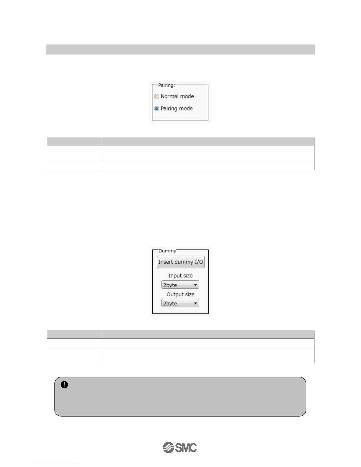
(4) Pairing
Details of Pairing. The radio buttons used for pairing are only displayed in Administrator mode. They are
grayed out in Monitor mode. They can only be set when power is not supplied.
•Details of pairing radio button
Description
Explanation
Pairing disabled
Button to change to Normal (non-pairing) mode. Indicates that the current status is Normal
(pairing disabled) mode.
Pairing enabled
Button to change to Pairing mode. Indicates that the current status is Pairing mode.
(5) Dummy slave
The dummy slave can register a "Dummy area" in the I/O map. A wireless slave unit can be added without
changing the I/O map by registering the wireless slave unit to the "Dummy area" even after system
construction.
The wireless slave unit allocation order to the I/O map is from smallest channel to largest channel
registered by the wireless channel which has been set during slave unit registration.
At the time, the wireless channel in which no wireless slave unit is registered will be ignored.
When adding new wireless slave unit, it may be required to change the I/O map depending on the wireless
channel number.
The dummy slave can be registered only with the wireless master unit.
•Details of dummy slave radio button
Description
Explanation
Insert
Button to move the dummy slave to Registered slaves.
Input size
Set the input size for the dummy slave (0 to 16 byte).
Output size
Set the output size for the dummy slave (0 to 16 byte).
: Refer to 5.2 Registration of dummy slave (page 74) for details and registration of dummy slaves.
•To reserve the dummy slave registration, it is necessary to set the number of inputs/outputs.
If a slave unit with inputs/outputs which are different from the set numbers is registered, the I/O
map should be changed.
Page 31

-30-
No.EX※※-OMV0017-B
3.3. Display for wireless slave
The tabs available at the upper left of the I/O configurator for NFC window consists of the Information
(page 30), Input/Output monitor (page 32) and setting (page 36).
3.3.1. Information tab
The tab for Information consists of (A) Unit information, (B) System configuration and (C) Description.
(A) Unit information
The unit information area indicates the unit information.
•Wireless slave unit information
Description
Content
NFC access
Energized
Not energized
Part No.
Product number of the wireless slave unit
Available
Available
PID
Wireless slave unit PID
Available
Available
Firmware version
Displays software version of the wireless slave unit.
Available
Available
Occupied points for the
module input/output
Input and output size of the wireless slave unit.
Available
Not available
(C)
(A)
(B)
Page 32

-31-
No.EX※※-OMV0017-B
(B)System Construction
System configuration shows the configuration information of the wireless slave module.
In System configuration, connected I/O units can be checked by clicking the wireless slave unit.
(C) Description
Description of the unit selected in the System configuration. The Description is displayed by clicking on the
wireless unit or I/O unit in the System configuration.
: Description varies depending on the unit type. Refer to 3.4 Detailed information of units (page 40) for details.
Error display:
Error is
indicated.
Page 33

-32-
No.EX※※-OMV0017-B
3.3.2. Input/Output monitor tab
In the I/O monitor tab, the wireless unit I/O map data can be monitored. Diagnostic information or details of
input/output can be checked by double clicking the line in the display. It is possible to switch between input
map and ouput map using the tabs shown. Forced output mode (4.3 Forced output) (page 58) can be selected
in the Output tab.
3.3.2.1. Input tab
Input tab shows the input map information of the wireless slave unit.
•Input display
Display
Content
Displayed items
Address
Displays the input map address of the wireless slave.
0 to 15
Wireless CH
Wireless unit channel.
--, ch001 to 127
PID
Wireless unit PID
Individual per unit.
Data (byte)
Input data is displayed in byte.
0x00 to 0xFF, no information
Data (bit)
Input data is displayed in bit.
00000000 to 11111111, no information
Details
Details of input data.
Slave input
Page 34

-33-
No.EX※※-OMV0017-B
3.3.2.2. Output tab
Output tab shows the output map information of the wireless unit.
•Output display
Description
Content
Displayed items
Address
Displays the output map address of the wireless slave.
0 to 15
Wireless CH
Wireless unit channel.
--, ch001 to 127
PID
Wireless unit PID
Individual per unit.
Data (byte)
Output data is displayed in byte.
0x00 to 0xFF, no information
Data (bit)
Output data is displayed in bit.
00000000 to 11111111, no information
Details
Details of output data.
Slave output
Page 35

-34-
No.EX※※-OMV0017-B
3.3.2.3. IO Detail
IO Detail will open by double clicking the line of the required address of the IO unit which is connected to the
wireless unit.
Double-click
Page 36

-35-
No.EX※※-OMV0017-B
IO unit information or IO data & diagnostics can be checked in the IO Detail window. The Diagnostic error type
is represented by different background colours. The meaning of background colour can be checked by
clicking [>>].
•Background colour
Background
colour
Description
Description
Open
Detection of unconnected load
: Invalid in initial state. Enable the function from the I/O configurator (WEB version).
Short
Short circuit detection
Count Over
Contact frequency upper limit detection
: Invalid in initial state. Enable the function from the I/O configurator (WEB version).
: Description varies depending on the unit type Refer to 3.4 Detailed information of units (page 40) for details.
Page 37

-36-
No.EX※※-OMV0017-B
3.3.3. Setting tab
The configuration of the connected unit can be changed using the setting tab. It consists of setting items
(page 37) and setting window (page 38) (Slave setting and Pairing setting).
Setting items
Setting display
Page 38

-37-
No.EX※※-OMV0017-B
3.3.3.1. Setting items
Control panel for setting consists of 2 radio buttons and 3 buttons.
•Radio buttons for selecting the setting window.
No.
Description
Function
A
Slave unit setting
Switch to the slave unit setting display. Occupied points for the module input/output can be
set.
B
Pairing setting
Switch to the pairing setting display. Switch to Pairing mode.
•Buttons for setting
No.
Description
Functions
1
Reset module
Set parameters are returned to the time of power supplied to the wireless unit. Click Reset
module in order to reflect the parameter setting while power is supplied.
2
Export
Button to export the configuration of the wireless unit to a PC (saved as file type ".smc").
Refer to 4.4. Export settings for use (page 63).
3
Import
Button to import the saved configuration of the wireless unit from a PC (imported from file
type ".smc"). Refer to 4.5. Import settings for use (Page 65).
: When the Reset module button is used, the wireless unit restarts and Ethernet communication or wireless communication is
temporarily interrupted.
(3)
(2)
(1)
(A)
(B)
Page 39

-38-
No.EX※※-OMV0017-B
3.3.3.2. Setting window
(A) Slave unit setting
Window for setting slave
Page 40

-39-
No.EX※※-OMV0017-B
•Slave setting items
Item
Explanation
Hold/Clear (unit)
Define all settings in the output operation status when the Fieldbus communication is
disconnected.
CLEAR: Clear the output.
HOLD: Fix the output at the current value.
Software control: Clear, Hold or Set for individual points can be set by software bit.
: For details of the Software Control refer to 4.2 Software Control (page 56) for setting in I/O Configurator
for NFC)
Occupied points for
the module input
Set the number of inputs which can be controlled by the wireless slave unit.
Setting range: 0 to 128 points (0 to 16 bytes). Increase or decrease by 16 points.
Occupied points for
the module output
Set the number of inputs which can be controlled by the wireless slave unit.
Setting range: 0 to 128 points (0 to 16 bytes). Increase or decrease by 16 points.
The module output point includes the number of points of the valve manifold output.
Occupied points for
the valve manifold
output
Set the number of outputs to be allocated to the valve manifold output from the number of
points set in the module output size.
As the valve manifold output point is included in the module output point, the number of
effective points are limited within the setting range of the module output point.
Setting range: 0 to 32 points (0 to 4 bytes). Increase or decrease by 8 points.
Wireless
communication
Define the operation status of wireless communication.
Active: Wireless communication is available.
Idle: Disconnect the wireless communication.
Analogue input
update time
Set the data update time of the analogue input unit connected to the wireless slave.
Setting range: 0.1/0.2/0.5/1/2/5/10/30/60 s (Initial value 1 s)
The analogue input update time is set for every wireless slave unit.
I/O unit assignment
direction
Define the address assignment direction of the EX600 I/O units connected to the wireless
master unit.
The address assignment direction is changed by mode 1/mode 2. Be careful about the I/O
map.
I/O assignment Order of Wireless Master/Slave Module
(Refer to page 50)
Mode 1: Assignment to the right from the end plate.
Mode 2: Assignment to the left from the wireless unit.
Page 41

-40-
No.EX※※-OMV0017-B
(B) Pairing setting
Setting for wireless communication between the wireless master unit and wireless slave unit. It is necessary
to set the operation mode to Pairing setting when registering the wireless slave to wireless master. Pairing
setting display.
•Radio button for selecting Pairing mode.
Description
Explanation
Pairing disabled
Button to change to Normal (non-pairing) mode. Indicates that the current status is Normal
(pairing disabled) mode.
Pairing enabled
Button to move to Pairing mode. Indicates that the current status is Pairing mode.
3.4. Detailed information of units
3.4.1. Information tab
Each EX600 unit stores its specific information. The information of the unit connected to the wireless
master/slave module can be monitored usig the I/O configurator for NFC.
The EX600 unit is accessed using the information tab.
Procedure for detailed information
Information tab the number of units in System configuration Description is displayed.
: Refer to the operation manual for EX600-W # for I/O units which can be connected to the wireless unit.
Page 42

-41-
No.EX※※-OMV0017-B
(a) Wireless unit
Detailed information of the main body and valve can be checked in the wireless unit.
a-1). Main body
•Detailed Information (main body)
Description
Content
Part No.
Wireless unit product number
PID
Wireless unit PID
Tag
Wireless unit user memo
Diagnostic information
The wireless unit status is displayed in 4 bytes of hexadecimal number.
Display of diagnostic information error
Refer to the Operation Manual for details of diagnostic information.
Hold/Clear (unit)
Displays the output operation when communication of the wireless unit is disconnected.
Input/output offset
Displays the start position of the address to which the selected unit is mapped in the I/O
mapping.
Input/output size
Control input and output size of the wireless unit.
I/O using
The number of allocatted Input and output bytes actually used by the wireless unit.
I/O available
The number of allocatted input and output bytes which are available for use by the wireless
unit.
Input data
Displays Input data value which issent to the wireless unit.
Output data
Displays output data value sent from the wireless unit.
RSSI Average
The average signal strength received by the wireless unit.
: Refer to 4.1 Edit
the tag
Diagnostic information 3
Diagnostic information 1
Diagnostic information 2
Diagnostic information 4
Page 43

-42-
No.EX※※-OMV0017-B
a-2) Valve
•Detailed information (valve)
Description
Content
Part No.
Wireless master/slave product number
Unit No.
Mapped position for the valve. Displays the mapped position of the selected valve.
: Refer to the "Unit address order" of (A) Master unit setting (page 22) or (A) Slave unit setting (page 38)
for mapping position.
Diagnostic
information
Displays the mapped diagnostic data bits for the selected valve.
: Content of diagnostics
N: Normal Error is not detected
O: Bit Open Load is not connected (disabled at initial status)
S: Bit Short Short circuit of the load output is detected
L: Limit Over Contact operation exceeded the limit (disabled at initial status)
P: Power Short Short circuit of the load power supply is detected
Hold/Clear (unit)
Output operation when communication of the valve is disconnected
Input/output offset
Displays the start position of the address to which the selected unit is mapped on the I/O map.
Input/output size
Valve input/output size (Input size for valves is always 0 byte)
Input data
"--" is displayed for the valve (setting is only applicable to units with inputs).
Output data
Displays the output data valve which is sent to the selected valve.
Content of diagnostics
Address in the unit
Example: 4th. bit of byte 0
Page 44

-43-
No.EX※※-OMV0017-B
(b). Digital input unit
Digital input unit (product number: EX600-DXD)
•Detailed information (digital input unit)
Description
Content
Part No.
Displays the product number of the digital input unit which is selected.
Unit No.
Displays the mapped position of the selected digital input unit.
: Refer to the "Unit address order" of (A) Master unit setting (page 22) or (A) Slave unit setting (page 38)
for mapping position.
Diagnostic
information
Displays the mapped diagnostic data bits for the selected digital input unit.
: Content of diagnostics
N: Normal Error is not detected
O: Bit Open Load is not connected (disabled at initial status)
S: Bit Short Short circuit of the load output is detected
L: Limit Over Contact operation exceeded the limit (disabled at initial status)
P: Power Short Short circuit of the load power supply is detected
Hold/Clear (unit)
"--" is displayed for the input unit (setting is only applicable to units with outputs).
Input/output offset
Displays the start position of the address to which the selected unit is mapped on the I/O map.
Input/output size
Displays the IO size of the selected digital input unit. Output size is 0 byte.
Input data
Displays the input data value which is sent from the selected digital input unit.
Output data
"--" is displayed for the input unit (setting is only applicable to units with outputs).
Content of diagnostics
Address in the unit
Example: 3rd. bit of byte 1
Page 45

-44-
No.EX※※-OMV0017-B
(c). Digital output unit
Digital output unit (product number: EX600-DYB)
•Detailed information (digital output unit)
Description
Content
Part No.
Displays the product number of the selected digital output unit.
Unit No.
Displays the mapped position of the selected digital output unit.
: Refer to the "Unit address order" of (A) Master unit setting (page 22) or (A) Slave unit setting (page 38)
for IO mapping position.
Diagnostic
information
Displays the mapped diagnostic data bits for the selected digital output unit.
: Content of diagnostics
N: Normal Error is not detected
O: Bit Open Load is not connected (disabled at initial status)
S: Bit Short Short circuit of the load output is detected
L: Limit Over Contact operation exceeded the limit (disabled at initial status)
P: Power Short Short circuit of the load power supply is detected
Hold/Clear (unit)
Displays the output operation when the communication of the digital output unit which is
selected is disconnected.
Input/output offset
Displays the start position of the address to which the selected unit is mapped on the I/O map.
Input/output size
Displays the input/output size of the selected digital output unit. Input size is 0 byte.
Input data
"--" is displayed for the output unit (setting is only applicable to units with inputs).
Output data
Displays the output data value which is sent to the selected digital output unit.
Content of diagnostics
Address in the unit
Example: 4th bit of byte0
Page 46

-45-
No.EX※※-OMV0017-B
(d). Digital I/O unit
Digital output unit (product number: EX600-DMF)
•Detailed information (digital input/output unit)
Description
Content
Part No.
Displays the product number of the selected digital input/output unit.
Unit No.
Displays the mapped position of the selected digital input/output unit.
: Refer to the "Unit address order" of (A) Master unit setting (page 22) or (A) Slave unit setting (page 38)
for IO mapping position.
Diagnostic
information
Displays the mapped diagnostic bits for the selecteddigital input/output unit.
: Content of diagnostics
N: Normal Error is not detected
O: Bit Open Load is not connected (disabled at initial status)
S: Bit Short Short circuit of the load output is detected
L: Limit Over Contact operation exceeded the limit (disabled at initial status)
P: Power Short Short circuit of the load power supply is detected
Hold/Clear (unit)
Displays the output operation when the communication of the digital input/output unit which is
selected is disconnected.
Input/output offset
Displays the start position of the address to which the selected unit is mapped on the I/O map.
Input/output size
Displays the I/O size of the selected digital input/output unit.
Input data
Displays the input data value which is sent from the selected digital input/output unit.
Output data
Displays the output data value which is sent to the selected digital input/output unit.
Diagnostic content
Address in the unit
Example: 3rd. bit of byte 1
Page 47

-46-
No.EX※※-OMV0017-B
(e). Analogue input unit
Analogue input (product number: EX600-AXA)
•Detailed information (analogue Input unit)
Description
Content
Part No.
Displays the product number of the selected analogue input unit.
Unit No.
Displays the mapped position of the selected analogue input unit.
: Refer to the "Unit address order" of (A) Master unit setting (page 22) or (A) Slave unit setting (page 38)
for IO mapping position.
Input/output offset
Displays the start position of the address to which the selected unit is mapped on the I/O map.
Input/output size
Displays the input/output size of the analogue input unit which is selected.
Output size is 0 byte.
Input data
Displays the input data value which is sent from the selected analogue input unit.
Output data
"--" is displayed for the input unit (setting is only applicable to units with outputs).
Status display:
No alarm: (OK)
Alarm generated: (Details of error)
: Refer to 8.Error Code List on page 0 for
details of errors.
Page 48

-47-
No.EX※※-OMV0017-B
(f). Analogue output unit
Analogue output (product number: EX600-AYA)
•Detailed information (analogue output unit)
Description
Content
Part No.
Displays the product number of the selected analogue output unit
Unit No.
Displays the mapped position of the selected analogue output.
: Refer to the "Unit address order" of (A) Master unit setting (page 22) or (A) Slave unit setting (page 38)
for IO mapping position.
Input/output offset
Displays the start position of the address to which the selected unit is mapped on the I/O map.
Input/output size
Displays the input/output size of the selected analogue output unit. Input size is 0 byte.
Input data
"--" is displayed for the output unit (setting is only applicable to units with inputs).
Output data
Displays the output data value which is sent to the selected analogue output unit.
Status display:
No alarm: (OK)
Alarm generated: (Details of error)
: Refer to 8. Error Code List on page 0 for
details of errors.
Page 49

-48-
No.EX※※-OMV0017-B
(g). Analogue I/O unit
Analogue input/output unit (product number: EX600-AMB)
•Detailed information (analogue I/O unit)
Description
Content
Product No.
Displays the product number of the selected analogue input/output unit.
Unit No.
Displays the mapped position of the selected analogue input/output unit.
: Refer to the "Unit address order" of (A) Master unit setting (page 22) or (A) Slave unit setting (page 38)
for IO mapping position.
Input/output offset
Displays the start position of the address to which the selected unit is mapped on the I/O map.
Input/output size
Displays the input/output size of the analogue input/output unit which is selected.
Input data
Displays the input data value which is sent from the selected analogue input/output unit.
Output data
Displays the output data value which is sent to the selected analogue input/output unit.
Status display:
No alarm: (OK)
Alarm generated: (Details of error)
: Refer to 8. Error Code List on page0 for
details of errors.
Page 50

-49-
No.EX※※-OMV0017-B
3.4.2. Details of I/O monitor tab
By clicking the IO Detail tab, the information of the selected unit, diagnostic status, Byte or Bit value , or
analogue input/output can be checked.
Procedure to display the details of IO unit information
I/O monitor tab double click the line in which the unit to be checked is mapped IO Detail is displayed
: Refer to the operation manual for EX600-W # for the I/O unit which can be connected with the wireless unit.
(a). Wireless unit (valve)
•IO Detail (wireless master/slave unit (valve))
Description
Content
PID
Displays the PID of wireless master/slave to which the selected valve is connected.
Tag
Displays the tag of wireless master/slave to which the selected valve is connected.
Wireless channel
Displays the channel name of wireless master/slave to which the selected valve is connected.
Master is displayed for the master. 1 to 127 is displayed for the slave.
Part No.
Displays the product number of the wireless master/slave to which the selected valve is
connected.
Unit offset
Displays the start position of the address to which the selected unit is mapped on the IO map.
Unit No.
Displays the mapped position of the selected valve.
(relates to position of the unit within the manifold).
: Refer to the "Unit address order" of (A) Master unit setting (page 22) or (A) Slave unit setting (page 38)
for IO mapping position.
Page 51

-50-
No.EX※※-OMV0017-B
(b). Digital input unit
Digital input unit (product number: EX600-DXD)
•IO unit information (digital input unit)
Description
Content
PID
Displays the PID of wireless master/slave to which the digital input unit is connected.
Tag
Displays the tag of wireless master/slave to which the selected digital input unit is connected.
Wireless channel
Displays the channel name of wireless master/slave to which the selected digital input unit is
connected. Master is displayed for the master. 1 to 125 is displayed for the slave.
Part No.
Displays the product number of the selected digital input unit.
Unit offset
Displays the start position of the address to which the selected unit is mapped on the IO map.
Unit No.
Displays the mapped position of the selected digital input unit (relates to position of unit within
manifold).
: Refer to the "Unit address order" of (A) Master unit setting (page 22) or (A) Slave unit setting (page 38)
for IO mapping position.
Page 52

-51-
No.EX※※-OMV0017-B
(c). Digital output unit
Digital output unit (product number: EX600-DYB)
•IO unit information (digital output unit)
Description
Content
PID
Displays the PID of wireless master/slave to which the selected digital output unit is
connected.
Tag
Displays the tag of wireless master/slave to which the selected digital output unit is connected.
Wireless channel
Displays the channel name of wireless master/slave to which the selected digital output unit is
connected. Master is displayed for the master. 1 to 127 is displayed for the slave.
Part No.
Displays the product number of the selected digital output unit.
Unit offset
Displays the start position of the address to which the selected unit is mapped on the IO map.
Unit No.
Displays the mapped position of the selected digital output unit (relates to position of unit
within manifold).
: Refer to the "Unit address order" of (A) Master unit setting (page 22) or (A) Slave unit setting (page 38)
for IO mapping position.
Page 53

-52-
No.EX※※-OMV0017-B
(d). Digital I/O unit
Digital output unit (product number: EX600-DMF)
•IO unit information (digital input/output unit)
Description
Content
PID
Displays the PID of wireless master/slave to which the selected digital input/output unit is
connected.
Tag
Displays the tag of wireless master/slave to which the selected digital input/output unit is
connected.
Wireless channel
Displays the channel name of wireless master/slave to which the selected digital input/output
unit is connected. Master is displayed for the master. 1 to 127 is displayed for the slave.
Part No.
Displays the product number of the selected digital input/output unit.
Unit offset
Displays the start position of the address to which the selected unit is mapped on the IO map.
Unit No.
Displays the mapped position of the selected digital input/output unit (relates to position of unit
within manifold).
: Refer to the "Unit address order" of (A) Master unit setting (page 22) or (A) Slave unit setting (page 38)
for IO mapping position.
Page 54

-53-
No.EX※※-OMV0017-B
(e). Analogue input unit
Example of analogue input unit (product number: EX600-AXA)
•IO unit information (analogue input unit)
Description
Content
PID
Displays the PID of wireless master/slave to which the analogue input unit is connected.
Tag
Displays the tag of wireless master/slave to which the selected analogue input unit is
connected.
Wireless channel
Displays the channel name of wireless master/slave to which the selected analogue input unit
is connected. Master is displayed for the master. 1 to 127 is displayed for the slave.
Part No.
Displays the product number of the selected analogue input unit.
Unit offset
Displays the start position of the address to which the selected unit is mapped on the IO map.
Unit No.
Displays the mapped position of the selected analogue input unit (relates to position of unit
within manifold).
: Refer to the "Unit address order" of (A) Master unit setting (page 22) or (A) Slave unit setting (page 38)
for IO mapping position.
•Channel status (analogue input unit))
Data format
Displayed analogue value
Offset binary、Sign and Magnitude、2’s
Complement
±□□□ mA (current range)
±□□□ V (voltage range)
Scaled
±□□…□
:Refer to I/O Configurator on the website for data format.
IO unit information
Input/output value
of the channel
Status display:
No alarm: (OK)
Alarm generated: (Details of error)
: Refer to 8.Error Code List on page118
for details of errors.
Page 55

-54-
No.EX※※-OMV0017-B
(f). Analogue output unit
Example of analogue output unit (product number: EX600-AYA)
•IO unit information (analogue output unit)
Description
Content
PID
Displays the PID of wireless master/slave to which the analogue output unit is connected.
Tag
Displays the tag of wireless master/slave to which the selected analogue output unit is
connected.
Wireless channel
Displays the channel name of wireless master/slave to which the selected analogue output
unit is connected. Master is displayed for the master. 1 to 127 is displayed for the slave.
Part No.
Displays the product number of the selected analogue output unit.
Unit offset
Displays the start position of the address to which the selected unit is mapped on the IO map.
Unit No.
Displays the mapped position of the selected analogue output unit (relates to position of unit
within manifold).
: Refer to the "Unit address order" of (A) Master unit setting (page 22) or (A) Slave unit
setting (page 38) for IO mapping position.
•Channel status (analogue output unit)
Data format
Displayed analogue value
12-Bit-Resolution,
11-Bit-Resolution
±□□□ mA (current range)
±□□□ V (voltage range)
Scaled
±□□…□
:Refer to I/O Configurator on the website for data format.
IO unit information
Input/output value
of the channel
Status display:
No alarm: (OK)
Alarm generated: (Details of error)
: Refer to 8.Error Code List on page118
for details of errors.
Page 56

-55-
No.EX※※-OMV0017-B
(g). Analogue I/O unit
Example of analogue output unit (product number: EX600-AMB)
•IO unit information (analogue input/output unit)
Description
Content
PID
Displays the PID of wireless master/slave to which the analogue input/output unit is
connected.
Tag
Displays the tag of wireless master/slave to which the selected analogue input/output unit is
connected.
Wireless channel
Displays the channel name of master/slave to which the selected analogue input/output unit is
connected. Master is displayed for the master. 1 to 127 is displayed for the slave.
Part No.
Displays the product number of the selected analogue input/output unit.
Unit offset
Displays the start position of the address to which the selected unit is mapped on the IO map.
Unit No.
Displays the mapped position of the selected analogue input/output unit (relates to position of
unit within manifold).
: Refer to the "Unit address order" of (A) Master unit setting (page 22) or (A) Slave unit
setting (page 38) for IO mapping position.
•Channel status
Data format
Displayed analogue value
12-Bit-Resolution,
11-Bit-Resolution
±□□□ mA (current range): Input or output value
±□□□ V (voltage range): Input or output value
Scaled
±□□---□: Input or output value
:Refer to I/O Configurator on the website for data format.
IO unit information
Input/output value
of the channel
Status display:
No alarm: (OK)
Alarm generated: (Details of error)
: Refer to 8. Error Code List on page118
for details of errors.
Page 57

-56-
No.EX※※-OMV0017-B
4. Setting Function
There are functions which can be set more easily by using the I/O configurator for NFC for setting.
•Edit TAG (page 56)
•Software Control(page 56)
•Forced output (page 58)
•Export of setting (page 63)
•Import of setting (page 65)
•Reading of the initial value (page 66)
•Initialize the product (page 67)
4.1. Edit TAG
(1) Only the SI unit can be set using the TAG edit. Up to 15 alphanumeric characters can be entered. Click the
Edit TAG button at the bottom of the window.
(2) The TAG edit window will open by clicking the "Edit TAG" button. Enter a new tag name and click the
Confirm button. The name can be returned to the previous status by clicking PREV during editing.
4.2. Software Control
With the "Clear/Hold/Software control" of Master/slave unit setting, the output operation for when the Ethernet
communication is disconnected can be selected for valve output or output unit independently using CLEAR,
HOLD or SET. The values for the Hold/Clear for each valve output or output unit are stored in the unit with
output.
Value
Content
HOLD
Maintain the value before Hold/Clear.
Clear
0 for Hold/Clear
SET
1 for Hold/Clear
: Editing is possible from the Description of the Information tab when Hold/Clear is set to Software Control. In order to set the Software
Control of Hold/Clear, change the setting using the Master unit setting or Slave unit setting in the Set tab.
: The output operation when wireless communication is disconnected, the status is HOLD regardless of the setting of the Software
Control.
Page 58

-57-
No.EX※※-OMV0017-B
Hold/Clear setting procedure
(1) Details of the output unit information.
(Refer to (C) Description (pate 15, 31) to show the detailed information.)
(2) The window for Unit HOLD/CLR/SET setting appears by clicking the Edit button.
Displayed when Software
Control is selected.
From the left
Bit0,1,2,3,4,5,6,7
Page 59

-58-
No.EX※※-OMV0017-B
(3) Upper case letters are used to express the current status of Clear/Hold. The Settable values are C
(CLEAR), H (HOLD) or S (SET). Enter 8 characters. When the required values have been entered, click
the "Save all" button to store the data.
: When CLEAR and HOLD is set for HOLD/CLR/SET, the window below will be displayed.
Hold/Clear: CLEAR Hold/Clear: HOLD
4.3. Forced output
4.3.1. Forced output conditions
The I/O configurator for NFC can directly command the wireless master/slave.
Operating conditions for Forced output.
[Forced output from the wireless master]
[Forced output from the wireless slave]
Forced output
conditions
Login from the Administrator mode.
Not connected with the higher PLC by
Ethernet.
Login from the Administrator mode.
Not wirelessly connected with wireless master.
Applicable item for
forced output
Wireless master/unit
Wireless slave
Page 60

-59-
No.EX※※-OMV0017-B
4.3.2. Forced output procedure
This is the forced output procedure using individual bits. Change the tab to I/O monitor to move to forced
output mode. Then, click "Enforce ON" on the upper right of the window. Then Click Yes.
The window below appears when the mode is changed to forced output mode. Select the output unit to be
forced output and double click it.
Double-click
Page 61

-60-
No.EX※※-OMV0017-B
The IO Detail window is displayed. Then, select the Bit (B0 to B7) to be forced output and set to 1. The set
value is output by clicking the Enforce button at the bottom of the window. The power supply for output is
necessary to activate the output equipment for forced output mode. Refer to the Operation Manual for the
SMC Wireless System for details of the power supply for output.
Forced output is possible also using bytes. Enter the value between 0x00 and 0xFF to the data (byte). The
value in bytes is output by clicking the Enforce button. This is the forced output procedure for the digital unit.
Page 62

-61-
No.EX※※-OMV0017-B
•Forced output (analogue unit)
The window for the forced output for analogue unit is displayed. For forced output for the analogue unit, enter
the values according to the analogue range (analogue range can be selected by the I/O configurator for WEB).
Enter the values. The analogue value will be output by clicking the Enforce button. The power supply for
output is necessary to activate the output equipment for forced output mode. Refer to the Operation Manual
for the SMC Wireless System for details of the power supply for output.
When the window below appears, the input value was outside the setting range. Enter a value within the
range.
0.00 1.00
Page 63

-62-
No.EX※※-OMV0017-B
4.3.3. Forced output release procedure
First, check the box for Enforce ON. Then Click Yes. Click Yes on the following window. Forced output mode
is released. Finally. click the Refresh button to update the information in the window. Forced output can also
be released by turning off the power supply.
: Caution for releasing forced output mode: The operation after releasing the forced output is different for wireless master and slave.
Set values are maintained for the wireless master, but they are not maintained for the wireless slave.
Page 64

-63-
No.EX※※-OMV0017-B
4.4. Export Settings
The Export settings tab enables the setting of the unit connected with current NFC reader/writer to be saved
to a PC in the format of ".smc". The Import enables the unit setting to be reflected in the other unit. Refer to
the table below for settings which can be exported.
Procedure for exporting the settings
(1) Open the window to save the file by clicking the "Export" button.
(2) Input the file name and store the file.
(1)
(2)
Page 65

-64-
No.EX※※-OMV0017-B
•Export/import setting
Item
Master
Slave
(EX600-WSV#)
(EX600-WEN#)
(EX600-WPN#)
Master setting/
slave setting
Hold/Clear (unit)
○ ○ ○
Occupied points for the module input
○ ○ ○
Occupied points for the module output
○ ○ ○
Occupied points for the valve manifold
output
○ ○ ○
Wireless communication
○ ○ ○
Analogue input update time
-
-
○
I/O unit assignment direction
○ ○ ○
Slave registration/
pairing setting
Pairing disabled/enabled
○ ○ ○
Ethernet setting
IP address setting mode
○
-
-
IP address
○
-
-
Auto MDI/MDI-X
○
-
-
Duplex
○
-
-
Speed
○
-
-
System setting
I/O assignment
○
-
-
System input size
○
-
-
System output size
○
-
-
Diagnostic assignment
○
○
-
Number of registered slave
○
○
-
Analogue output update time
○
○
-
Page 66

-65-
No.EX※※-OMV0017-B
4.5. Import Settings
The Import settings tab enables the set file in the format of ".smc" which is save in the PC to be read, and the
content of the unit connected with the NFC reader/writer can be changed to the content of the set file. This
function is applicable only between the same type of unit (between masters, or between slaves)
: Settings to be imported are the same as those to be exported. Refer to 4.4. Export Setting (page 63).
Procedure for importing the settings
(1) Click the "Import" button.
(2) Select the required file and click the Open. Select Yes to execute the import of settings.
(1)
(2)
Page 67

-66-
No.EX※※-OMV0017-B
4.6. Reading of the initial value
Click the "Read factory data" button to initialize or check the parameters in the window currently opened by
the setting tab (excluding slave unit registration and pairing setting). In order to reflect the setting, turn off the
power and on again or reset when the power is on. Turn on the power supply when the power is off.
Settings for which initial values are read:
•Wireless master: Master unit setting, Ethernet setting, system setting
•Wireless slave: Slave unit setting
Page 68

-67-
No.EX※※-OMV0017-B
4.7. Initialize
Perform Product initialization of the master unit setting or slave unit setting to initialize the product.
: After executing the function, this function saves and reflects the setting, and updates the information in the window. The operation is
not irreversible.
Page 69

-68-
No.EX※※-OMV0017-B
Some values set by the I/O configurator (WEB) are included in the initialized items. Refer to the table below
for the set items to be initialized.
•Initialized items (I/O Configurator (NFC version))
Initialized items
Master
Slave
(EX600-WSV#)
(EX600-WEN#)
(EX600-WPN#)
Set tab
Master/slave
unit setting
Hold/Clear ○ ○
○
Input size ○ ○
○
Output size ○ ○
○
Valve manifold output size
○ ○ ○
Wireless communication
○ ○ ○
Analogue input update time
- - ○
I/O unit assignment direction
○ ○ ○
Slave unit
registration
Pairing mode
○ ○ ○
Info. registered in master
- - ○
Pairing
setting
Pairing mode
○ ○ ○
Info. registered in slave
○ ○ -
Ethernet
setting
IP address setting mode
○ - -
IP address ○ -
-
Auto MDI/MDI-X
○ - -
Duplex ○ -
-
Speed ○ -
-
System
setting
I/O layout ○ -
-
System input size
○ - -
System output size
○ - -
Diagnostic allocation
○ ○ -
Number of connected slave
○ ○ -
Analogue output update time
○ ○ -
Information tab
Detailed
information
Tag ○ ○
○
- N/A
•Initialized items (I/O Configurator (WEB version))
Initialized items
Master
(EX600-WEN#)
(EX600-WPN#)
Slave
(EX600-WSV#)
Module Setting
Power Supply Voltage Monitor (Output)
○
○
Byte Order of Analogue Values
○
○
Channel Setting
OpenDiag ○ ○
HOLD/CLEAR
○
○
MAXCount ○ ○
CountOverDiag
○
○
CountReset
○
○
: Refer to the I/O Configurator (Web version) for item details.
Page 70

-69-
No.EX※※-OMV0017-B
5. Pairing of wireless unit
5.1. Pairing procedure of wireless unit
: Login to the Administrator mode to change to pairing mode.
Refer to 3.1.1 Login to administrator mode (page 13).
(1) Change the mode of the wireless slave unit to Pairing mode.
Change the pairing setting of the wireless slave unit to "Pairing enable" and reflect the change by clicking
Reset module or by re-supplying power.
: After switching the operation mode to Pairing mode, check that the W-NS LED on the wireless unit flashes in green and red alternately.
Refer to the Operation Manual for details of LEDs.
Page 71

-70-
No.EX※※-OMV0017-B
(2) Change the mode of the wireless master unit to Pairing mode.
Change the pairing setting of the slave unit registration of the wireless master unit to "Pairing enable" and
reflect the change by clicking Reset module or by re-supplying power. Then, update the contents on the
screen by clicking Refresh. (Registered wireless slave unit information will be displayed in the box of free
slave.)
: The Power supply for the wireless master/slave has to be on for registration of the slave unit.
: After switching the operation mode to Pairing mode, check that the W-NS LED on the wireless unit flashes in green and red alternately.
Refer to the Operation Manual for details of LEDs.
Page 72

-71-
No.EX※※-OMV0017-B
(3) Select the wireless channel
Register the required wireless channel by registering the slave unit to the wireless master unit. Select the
wireless channel and move it from the Free slaves box to Registered slaves box.
(Registration is not complete at this point. The status of the wireless slave unit will be shown as "Waiting
for registration".)
Moves to the Registered slaves box by
clicking this button.
Selected wireless channel is displayed.
Page 73

-72-
No.EX※※-OMV0017-B
(4) Determination of the registered information
Press Save reg-info to register the wireless slave unit to the wireless master.
Then, click Refresh to confirm that the setting has been reflected.
(When registration has been completed correctly, the status of the selected wireless slave unit will change
from "Waiting for registration" to "registered".
(When the wireless slave unit is registered correctly, the mode will change automatically.)
Make sure Registered is displayed.
Page 74

-73-
No.EX※※-OMV0017-B
(5) Change of operation mode of the wireless master unit
Change the pairing setting on the slave unit registration screen of the wireless master unit to "Pairing
disable" and reflect the change by clicking Reset module or by re-supplying power.
Now, the registration procedure for the wireless master unit and the wireless slave unit are complete.
When registering more than one wireless slave is required, repeat procedures (3) and (4).
It is also possible to register more than one wireless slave unit simultaneously to the wireless master unit.
•Registration should be performed with power supplied to both wireless master and wireless
slave units.
•For the Input and Output size of the wireless slave unit module, the setting of wireless
registration will be reflected to the wireless master unit.
When changing the number of Input and Output points of the wireless slave unit, wireless
registration should be performed again.
•The setting of the Input and Output points of the wireless master unit are valid all the time. Be
careful that the I/O map will be different if the setting is changed after constructing the I/O map.
(After changing, the setting is reflected by pressing the [Reset] button or by supplying the power
again.)
Page 75

-74-
No.EX※※-OMV0017-B
5.2. Registration of dummy slave
(1) Change of operation mode of the wireless master unit
Change the pairing setting of the slave unit registration of the wireless master unit to "Pairing enable" and
reflect the change by clicking Reset module or by re-supplying power. Then, update the contents on the
screen by clicking Refresh.
(2) Inputs/outputs setting of dummy slave
Set the number of inputs and outputs of the dummy slave.
(3) Insert the dummy slave to the required wireless channel
Select the required wireless channel and click Insert so that the set dummy slave is displayed in the box
for "Registered slaves".
(Dummy slave registration is not complete at this point. The status is "Waiting for registration".)
(4) Save the dummy slave registration information.
Click Save reg. info to reflect the registered information.
(When registration has been completed correctly, the status of the dummy slave will change to
"registered".)
(1)
(2)
(3)
(4)
Page 76

-75-
No.EX※※-OMV0017-B
6. Wireless system configuration example
The Wireless system configuration method is shown below. Perform the preparation according to section 2.
Preparation before use (page 7) before configuring the wireless system. The example below is based on the
Step 2 Setting/installation of the wireless unit of 6.1 Flow chart for using the wireless system (page 75) to
explaining the Example 1 of 6.2 System Configuration example (page 76).
6.1. Flow chart for using the wireless system (Refer to Step 2)
Step 1 Preparation before use (PC, Application)
(1) Install the NFC reader, writer and driver.
(2.2. Before starting the software)
(2) Install the I/O Configurator for NFC.
(2.3. Download the I/O Configurator (NFC version)
Step 2 Setting/installation of the wireless unit
(1) Set the number of occupied I/O points for the module and each parameter
of the "wireless slave".
(6.4. (1) Input and output size of the wireless slave)
(2) Set the number of occupied I/O points for the module and each parameter
of the "wireless master".
: Different from the I/O points of the whole system.
(6.5 Set the number of occupied I/O points for the module and each parameter
of the (2) "wireless master".)
(3) Set the "wireless master" system.
(6.6 (3) Set the "wireless master" system)
(4) Registration of wireless slave to the wireless master (pairing)
: Turn on the power supply to the master and slave unit.
(6.8 (4) Registration of wireless slave to the wireless master (pairing))
(5) I/O unit assembly.
(6) Installation and wiring.
(7) Set the Ethernet.port
Step 3 Connection to PLC
Note) Refer to the operation manual of the PLC manufacturer for connection to PLC and Configurator.
Page 77

-76-
No.EX※※-OMV0017-B
6.2. System Construction Example
An example of the set parameters and memory map of the wire master and slave (2 pcs.) used for wireless
system configuration are shown below.
Based on the example of Diagnostic allocation of the Operation Manual (page 50).
Unit 0
Unit 1
Unit 2
End
plate
DYB
Digital
output
1-byte
output
DXD
Digital
input
2-byte
output
EX600-WEN#
Wireless
master unit
2-byte
output
Valve
manifold
(16 points)
Wireless master unit setting parameter
Diagnostic allocation: Detailed
I/O mapping: Auto
Input size: 32 points/4 bytes
Output size: 32 points/4 bytes
Valve manifold output size: 16 points/2 bytes
I/O unit layout mode: Mode 1
Number of slave connection: 15 pcs.
Wireless master module construction
Input data: [Unit 1] Digital input unit (EX600-DXD): 2 bytes occupied
Output data: [Unit 0] Digital output unit (EX600-DYB): 1 byte occupied
[Unit 2] Wireless master unit (EX600-WEN#): 2 bytes occupied
Unit 0
Unit 1
Unit 2
Unit 3
End
plate
DYB
Digital
output
1-byte
output
AXA
Analogue
input
4-byte
input
DXD
Digital
input
2-byte
input
EX600-WSV#
Wireless slave
unit
4-byte
output
Valve
manifold
(32 points)
Wireless slave unit setting parameter
(Wireless channel 001)
Input size: 64 points/8 bytes
Output size: 48 points/6 bytes
Valve manifold output size: 32 points/4 bytes
I/O unit layout mode: Mode 1
Wireless slave module construction (Wireless channel 001)
Input data: [Unit 1] Digital input unit (EX600-DXD): 2 bytes occupied
[Unit 2] Analogue input unit (EX600-AXA): 4 bytes occupied
Output data: [Unit 0] Digital output unit (EX600-DYB): 1 byte occupied
[Unit 3] Wireless slave unit (EX600-WSV#): 4 bytes occupied
Unit 0
Unit 1
Unit 2
Unit 3
End
plate
DYB
Digital
output
1-byte
output
DXD
Digital
input
2-byte
input
DXB
Digital
input
1-byte
input
EX600-WSV#
Wireless slave
unit
0-byte
output
End
plate
(Output side)
Wireless slave unit setting parameter
(Wireless channel 002)
Input size: 32 points/4 bytes
Output size: 16 point/2 bytes
Valve manifold output size: 0 point/0 byte
I/O unit layout mode: Mode 1
Wireless slave module construction (Wireless channel 002)
Input data: [Unit 1] Digital input unit (EX600-DXD): 2 bytes occupied
[Unit 2] Digital input unit (EX600-DXB): 1 byte occupied
Output data: [Unit 0] Digital output unit (EX600-DYB): 1 byte occupied
[Unit 3] Wireless slave unit (EX600-WSV#): 0 byte occupied
Page 78

-77-
No.EX※※-OMV0017-B
•Memory map
Input data
Output data
Module name
Unit name
Module name
Unit name
byte0
System diagnosis 1
Wireless master module
DXB (Unit 0)
byte1
System diagnosis 2
EX600-WEN# (Unit 2)
Valve output: 16 points
byte2
System diagnosis 3
byte3
System diagnosis 4
Reserved
byte4
Wireless slave connection information
(Wireless channel 1-7; bit 0 are fixed at "0".)
Wireless slave module
(Wireless channel 001)
DYB (Unit 0)
byte5
Wireless slave connection information
(Wireless channel 8-15)
EX600-WSV# (Unit 3)
Valve output: 32 points
byte6
Wireless slave diagnostic information 1
(Wireless channel 1-7)
byte7
Wireless slave diagnostic information
(Wireless channel 8-15)
byte8
Wireless slave registration information
(Wireless channel 1-7; bit 0 are fixed at "0".)
byte9
Wireless slave registration information
(Wireless channel 8-15)
Reserved
byte10
Wireless master module
DXD (Unit 1)
Wireless slave module
(Wireless channel 002)
DYB (Unit 0)
byte11
Reserved
byte12
Reserved
byte13
Reserved
byte14
Wireless slave module
(Wireless channel 001)
AXA (Unit 1)
byte15
byte16
byte17
byte18
DXD (Unit 2)
byte19
byte20
Reserved
byte21
Reserved
byte22
Wireless slave module
(Wireless channel 002)
DXD (Unit 1)
byte23
byte24
DXB (Unit 2)
byte25
Reserved
Total
26 byte
12 byte
Page 79

-78-
No.EX※※-OMV0017-B
6.3. Preparation
STEP 1 Start the I/O Configurator (NFC version)
STEP 2 Login to Administrator mode
STEP 1 Start the I/O Configurator (NFC version)
(1) Start up the I/O Configurator (NFC) and connect the NFC reader/writer to the PC. "R/W detected" will turn
on in green when the PC detects the NFC reader/writer.
: Refer to 2. Preparation before use (page 7) for details of the connection of the NFC reader/writer.
Window when the NFC reader/writer is detected
Page 80

-79-
No.EX※※-OMV0017-B
(2) Hold the NFC reader/writer over the wireless slave (1).
(3) Click the "Refresh" button to update the information in the Information tab window of the wireless slave (1).
Update of the Information tab window
Page 81

-80-
No.EX※※-OMV0017-B
STEP 2 Login from the Administrator mode.
(1) Click the radio button for Administrator mode.
(2) Enter the password in the Password check window.
: The default password at the time of shipment from the factory is admin.
(3) When the following password input window is displayed, click Confirm.
"Password checking passed." is displayed when login is successful.
: When login is not successful, refer to 9. Troubleshooting (page 120).
Password check window
(3)
(2)
(1)
Page 82

-81-
No.EX※※-OMV0017-B
(4) Confirm that the radio button "Administrator mode" is checked during the login state.
: The mode is automatically changed to the monitor mode unless a mouse operation is made within 300 seconds in Administrator
mode.
Window to complete login
(4)
Page 83

-82-
No.EX※※-OMV0017-B
6.4. (1) Input and output size of the wireless slave
STEP 3 Change of parameter setting (wireless slave (1))
STEP 4 Change to pairing mode (wireless slave (1))
STEP 5 Change of parameter setting (wireless slave (2))
STEP 6 Change to pairing mode (wireless slave (2))
STEP 3 Change of parameter setting (wireless slave (1))
(1) Click the Properties tab to move to the Slave setting window.
(2) Click the "Refresh" button to update the information in the Slave setting window for the slave unit.
Slave unit setting window before updating (Wireless slave(1))
(1)
(2)
Page 84

-83-
No.EX※※-OMV0017-B
(3) Change the parameter setting of the wireless slave(1) to the values in the table for parameter setting.
(4) Click the "Save all" button to save the set values in the wireless slave (1).
Table for the change of parameter setting (wireless slave (1))
Setting items
Set value
Hold/Clear (unit)
Clear
Occupied points for the module input
64 point/8 byte
Occupied points for the module output
48 points/6 bytes
Occupied points for the valve manifold output
32 point/4 byte
Wireless communication
Active
Analogue input update time
1 s
I/O unit assignment direction
Mode 1
Default condition of the window for setting the slave unit (Wireless slave (1))
: Refer to 3.3.3.2. Setting window (page 38) for details of parameters.
(4)
(3)
Page 85

-84-
No.EX※※-OMV0017-B
(5) The parameter setting of the wireless slave(1) is complete.
Slave unit setting window after setting (Wireless slave (1))
Page 86

-85-
No.EX※※-OMV0017-B
STEP 4 Change to pairing mode (wireless slave (1))
(1) Click the radio button for Pairing setting to move to the pairing setting window.
From the slave unit setting window to Pairing setting (wireless slave (1))
(2) Click the "Refresh" button to update the information in the Pairing setting window.
Pairing setting window (Wireless slave (1))
(1)
(2)
Page 87

-86-
No.EX※※-OMV0017-B
(3) Click the radio button for Pairing mode.
(4) Click Yes to change to the pairing mode.
: Slave reset is requested when the mode is changed to pairing mode. The slave cannot be reset when the power supply is not
connected.
(5) Confirm that the radio button "Pairing mode" is checked.
Pairing check window (Wireless slave (1))
(4)
(3) (5)
Page 88

-87-
No.EX※※-OMV0017-B
STEP 5 Change of parameter setting (wireless slave (2))
(1) Hold the NFC reader/writer over the wireless slave (2).
(2) Click the "Refresh" button to update the window of the wireless slave (2).
(3) Click the radio button for Slave setting to move to the Slave unit setting window.
From the Pairing setting window to slave unit setting (wireless slave (2))
(3)
(2)
Page 89

-88-
No.EX※※-OMV0017-B
(4) Click the "Refresh" button to update the information in the Slave setting window for the slave unit.
(5) Change the parameter setting of the wireless slave(2) to the values in the table for parameter setting.
(6) Click the "Save all" button to save the set values in the wireless slave (2).
Table for the change of parameter setting (wireless slave (2))
Setting items
Set value
Hold/Clear (unit)
CLEAR
Occupied points for the module input
32 point/4 byte
Occupied points for the module output
16 point/2 byte
Occupied points for the valve manifold output
0 point/0 byte
Wireless communication
Active
Analogue input update time
1 s
I/O unit assignment direction
Mode 1
Default condition of the window for setting the slave unit (Wireless slave(2))
: Refer to 3.3.3.2. Setting window (page 38) for details of parameters.
(6)
(5)
(4)
Page 90

-89-
No.EX※※-OMV0017-B
(6) The parameter setting of the wireless slave (2) is complete.
Slave unit setting window after setting (Wireless slave (2))
Page 91

-90-
No.EX※※-OMV0017-B
STEP 6 Change to pairing mode (wireless slave (2))
(1) Click the radio button for Pairing setting to move to the pairing setting window.
From the slave unit setting window to Pairing setting (wireless slave (2))
(1)
Page 92

-91-
No.EX※※-OMV0017-B
(2) Click the radio button for Pairing mode.
(3) Click Yes to change to pairing mode.
: Slave reset is requested when the mode is changed to pairing mode. The slave cannot be reset when the power supply is not
connected.
(4) Confirm that the radio button "Pairing mode" is checked.
Pairing check window (Wireless slave (2))
(3)
(2) (4)
Page 93

-92-
No.EX※※-OMV0017-B
6.5. Set the number of occupied I/O points for the module and each parameter of the (2) "wireless
master"
STEP 7 Change of parameter setting
STEP7 Change of parameter setting
(1) Hold the NFC reader/writer over the wireless master.
Page 94

-93-
No.EX※※-OMV0017-B
(2) Click the "Refresh" button to update the window of the wireless master.
(3) Click the radio button for the Master setting to move to the master unit setting window.
Moves to master unit setting
Caution: The Power supply check window appears when power is not supplied to the wireless master.
Master unit setting can be changed when power is not supplied. Click the OK button to proceed.
Power supply check window
(3)
(2)
Page 95

-94-
No.EX※※-OMV0017-B
(4) Click the "Refresh" button to update the information in the Master unit setting window.
(5) Change the parameter setting of the wireless master to the values in the table for parameter setting.
(6) Click the "Save all" button to save the set values in the wireless master.
Values for parameter setting
Setting items:
Set value
Hold/Clear (unit)
CLEAR
Occupied points for the module input
32 point/4 byte
Occupied points for the module output
32 point/4 byte
Occupied points for the valve manifold output
16 point/2 byte
Wireless communication
Active
I/O unit assignment direction
Mode 1
Default image of the Master unit setting window
: Refer to 3.3.3.2. Setting window (page 38) for details of parameters.
(6)
(5)
(4)
Page 96

-95-
No.EX※※-OMV0017-B
(7) The parameter setting of the wireless master is complete.
Master unit setting window after setting
Page 97

-96-
No.EX※※-OMV0017-B
6.6. (3) Set the "wireless master" system
STEP 8 Change of system setting
STEP8 Change of system setting
(1) Click the radio button for System setting to move to the system setting window.
(2) Click the Refresh button to update the information in the System setting window.
Master unit setting window to System setting
(1)
(2)
Page 98

-97-
No.EX※※-OMV0017-B
(3) Change the system settings of the wireless master to the values in the table for system setting.
(4) Click the "Save all" button to save the set values in the wireless master.
Values for system setting
Setting items
Set value
I/O assignment
Automatic assignment
System input size
-
System output size
-
Diagnostic allocation
Details
Number of registered slave
15 pcs.
Analogue output update time
1 s
Default image of the System setting window
: Refer to 3.3.3.2. Setting window (page 38) for details of parameters.
System input and output size cannot be set when automatic I/O mapping is set.
(4)
(3)
Page 99

-98-
No.EX※※-OMV0017-B
(5) The system setting of the wireless master is complete.
System unit setting window after setting
Page 100

-99-
No.EX※※-OMV0017-B
6.7. (7) Ethernet setting for the wireless master
STEP 9 Change of Ethernet setting
STEP9 Change of Ethernet setting
(1) Click the radio button for Ethernet setting to move to the Ethernet setting window.
(2) Click the Refresh button to update the information in the Ethernet setting window.
System setting window to Ethernet setting
(1)
(2)
 Loading...