

SMC Networks EX600-W Series Manual
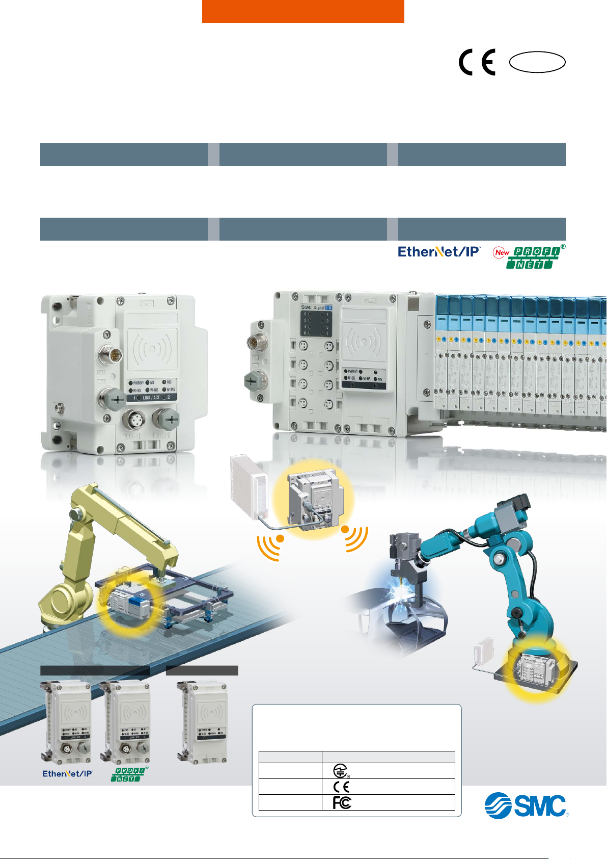
Wireless System
RoHS
Usable even in welding environments
Uses the 2.4 GHz ISM frequency band
Frequency hopping: Every 5 ms
Communication cables not
required
Reduced wiring work, space, and cost
Minimized disconnection risk
High-speed connectionNoise resistance
From power supply ON to start of
communication:
1
Min. 250 ms
*
*1 For remote
Number of I/O points
Max. 1280 inputs/1280 outputs
(Max. 128 inputs/128 outputs per module)
Communication response
Wireless communication signal
Response time:
5 ms
Compatible protocol
New
Material
handling robot
Remote
Remote moduleBase module
EX600-W Series
Base
Spot welding
Countries/Regions in which wireless is supported
This product cannot be used in countries where wireless is not
supported. Refer to page 23 for details on countries in which
the product can be used.
Country/Region Standards
Japan (Japanese radio law)
EU (CE marking/RE Directive)
USA (FCC)
Remote
CAT.E02-28B
B
Wireless System EX600-W Series
Provide safe and reliable communication
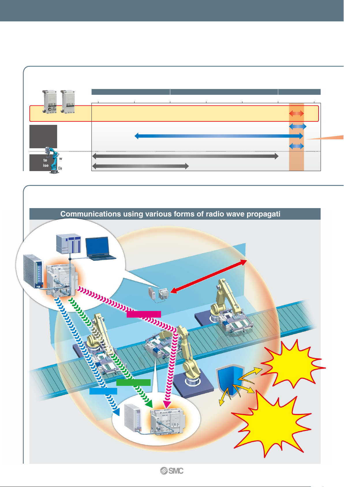
Uses the 2.4 GHz ISM frequency band
kHz MHz GHz
10 10 101 1100 100
Wireless System
Wireless LAN
Wireless
devices
Site
noise
welding machine
Electromagnetic heater, etc.
RFID
Bluetooth
AC/DC
Motor driver/
* ISM (Industrial, Scientific and Medical) radio bands: Radio bands reserved for the use of radio frequency energy for industrial,
scientific and medical purposes.
Provide stable communication
Communications using various forms of radio wave propagation
PLC
Powe r
supply
Base
Reflected wave
Transmitted wave
Direct wave
Communication possible
Automatic restoration
of communication
If the number of retries exceeds the stipulated value (32 times), a disconnection flag will
be output. The system will enter resync mode
and synchronization will be established. Once
completed, the normal operating conditions
will be restored, the disconnection flag will be
canceled, and control will resume.
in a 10 m radius
Noise in
electronic
circuits
Interference
from other
wireless
Remote
A
1
equipment
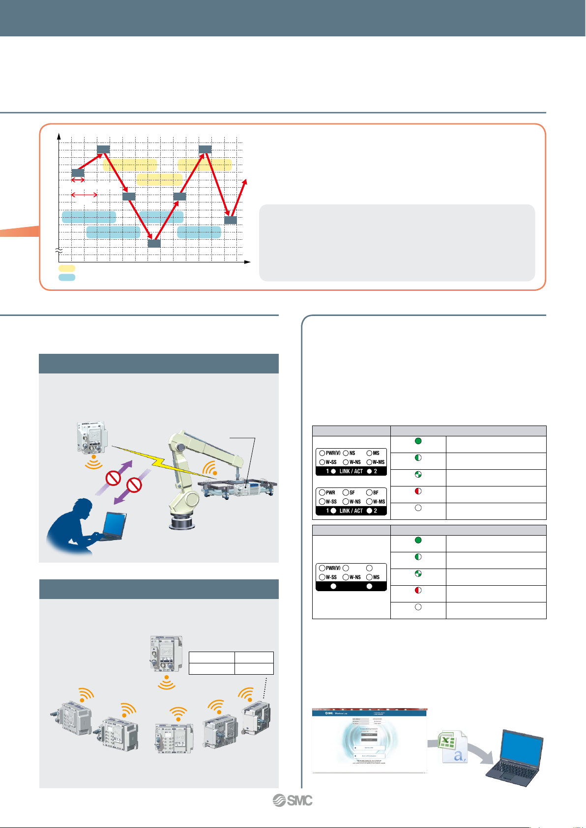
Frequency
Actual communication time
Communication frequency interference (for example, Wi-Fi)
5 ms
Frequency of the radio wave interference
Time
Wireless System EX600-W Series
Frequency hopping: Every 5 ms
A stable wireless environment is established using an original
protocol which is not affected by interference. Interference from other
wireless equipment is prevented.
Frequency Hopping
The communication technology rapidly changes frequency (hopping), to
prevent interference from other wireless equipment. When the frequency of
Wi-Fi and other wireless communications compete, or radio wave interference
is present, then other frequencies are used for communication. For details,
refer to technical data on page 23.
High security using encryption
Unauthorized access from outside is prevented by using
data encryption.
Base
Unauthorized access/
data falsification
Unauthorized
wiretapping
Remote
Removing
device
Point-to-Multipoint communication
Registration and communication of up to 127 remote
modules is possible.
Remote 1
Remote 2
* 1 to 15 units are recommended for simultaneous operation.
* It is possible to install multiple bases in the same area.
Base
Remote 3
EtherNet/IP™
PROFINET
Remote 4
Max. 127 units
Max. 31 units
Wireless communication status can be monitored.
<Monitoring the remote communication status>
The wireless system connection can be monitored during operation
according to the diagnostic data.
The installation location can be ascertained according to the intensity
level of the radio wave received by the unit display.
[Diagnostic data]
* When communication from the remote cannot be received
* When communication retry has exceeded the upper limit (32 times)
[Unit display]
For Base
EtherNet/IP™
PROFINET
For remote
* A received radio wave intensity level of 1 means the intensity is weak. Add
a base so that the wave intensity becomes level 3 or 2. Alternatively
remove the obstacle between the base and remote, or reduce the distance
between the base and remote.
<Communication status can be downloaded by a PC>
By connecting the base to a PC, it is possible to view log files which show the number of
retries or the received radio wave intensity. Log files are accessed by using a web browser to
connect to the built-in web server. The wireless environment and installation location can be
optimized by checking the number of retries and received radio wave intensity.
Web screen example
W-SS (Radio wave receiving intensity (For communication from remote to base))
Green LED is ON.
Green LED flashes. (1 Hz)
Green LED flashes. (2 Hz)
Red LED flashes.
OFF
W-SS (Radio wave receiving intensity (For communication from base to remote))
Green LED is ON.
Green LED flashes. (1 Hz)
Green LED flashes. (2 Hz)
Red LED flashes.
OFF
Received power level of all remotes is 3.
There are connected remotes with
received power level 2.
There are connected remotes with
received power level 1.
No remotes connected.
Remote module is not registered.
Received power level is 3.
Received power level is 2.
Received power level is 1.
Wireless communication is not connected.
Base module is not registered.
The log files showing the number of retries
or the received radio wave intensity, can
be downloaded in the form of a CSV file.
PC
A
2
Wireless System EX600-W Series
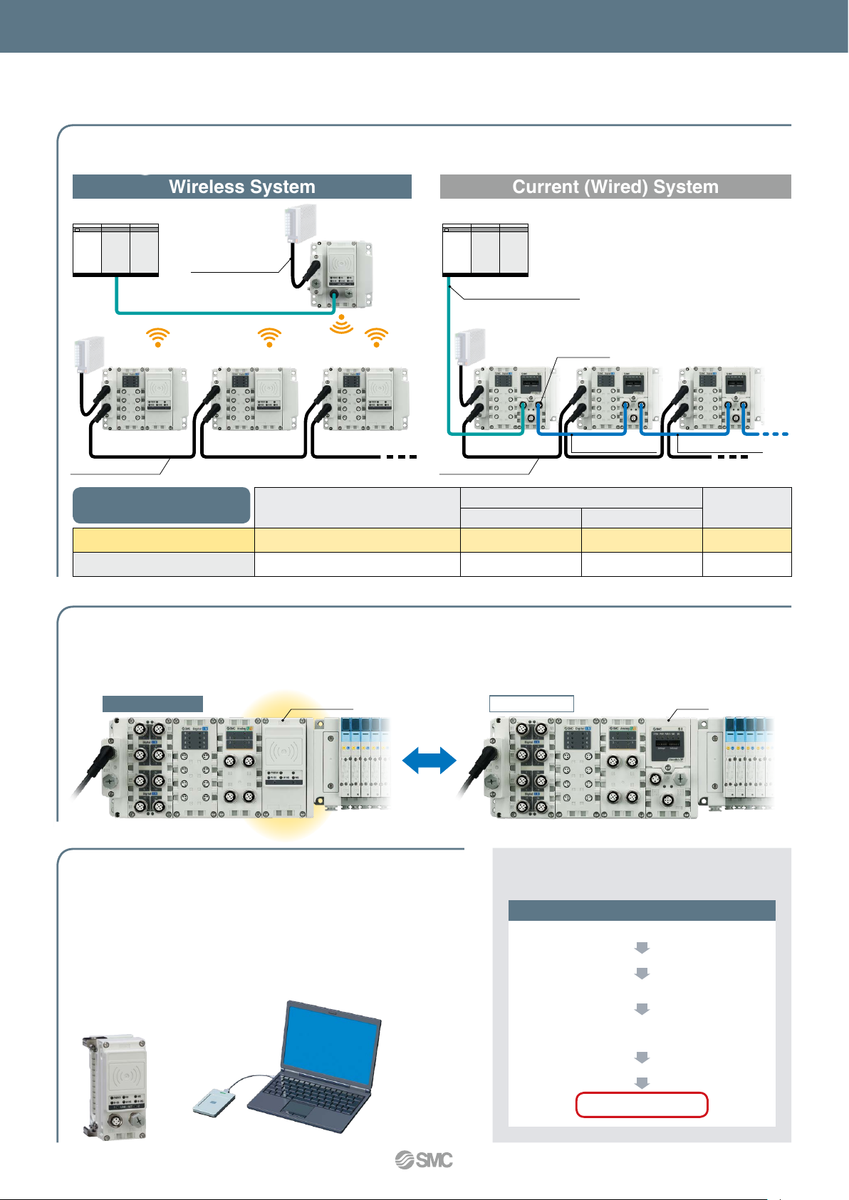
Wiring material cost and installation work-hours can be reduced.
Current (Wired) SystemWireless System
Power supply
Power supply line
Powe r
supply
Remote 1 Remote 2 Remote 3
Power supply line Power supply line
SI unit: Comparison when
15 units are connected
Wireless system
Communication line q
Number of communication devices
Current (Wired)
Base
…
3 units
Base: 1 unit
Remote: 15 units
SI unit: 15 units
15 units
PLCPLC
Communication line q
Powe r
supply
1 unit1 unit 2 units 3 units
SI unit
Communication line
q w
1 line
(Connector at one end)
1 line
(Connector at one end)
Interchangeability maintained
Connection interchangeability between EX600 series SI units is maintained.
Replacement of wireless and wired systems is possible.
Wireless system Wired system
Connector
2 units
Communication line w
— 1 place
14 lines
(Connector at both ends)
* Maximum I/O of base/remote
…
15 units
Communication line w
Communication
connectors
required
29 places
module is limited to 128 points.
SI unitWireless unit
NFC
contactless communication
(NFC: Near Field Communication)
Settings are possible using an NFC reader/writer and setting software.
(Some items can be set even when there is no power supplied.)
¡Write IP address to the base
¡Set the I/O points for the system and unit
¡Pairing of the base and remote
¡I/O monitoring
NFC reader/
writer
PC + Setting software
B
3
Configuration File
From SMC website
Documents/Download
Instruction Manuals
Fieldbus System
Serial Transmission System
EtherNet/IP™ Compatible
PROFINET Compatible
I/O Configurator for NFC
Configuration File
or
Wireless System EX600-W Series
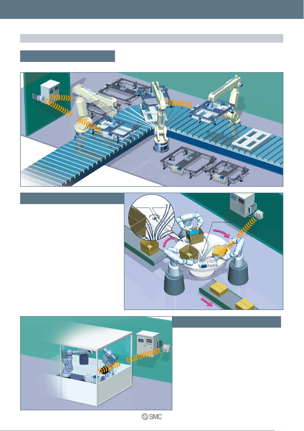
Application Examples
Tool change
Rotary table
¡Minimized disconnection risk
¡ Smaller diameter communication
cable/tubing
¡Communication cable is not necessary for moving parts.
¡Minimized disconnection risk
¡Shorter time for establishing communication (startup time)
Wired system
Power supply lineCommunication line
Power supply
line only
Blocking of radio waves
* The radio waves must not be blocked by nearby conductive
objects such as metal enclosures or covers.
4
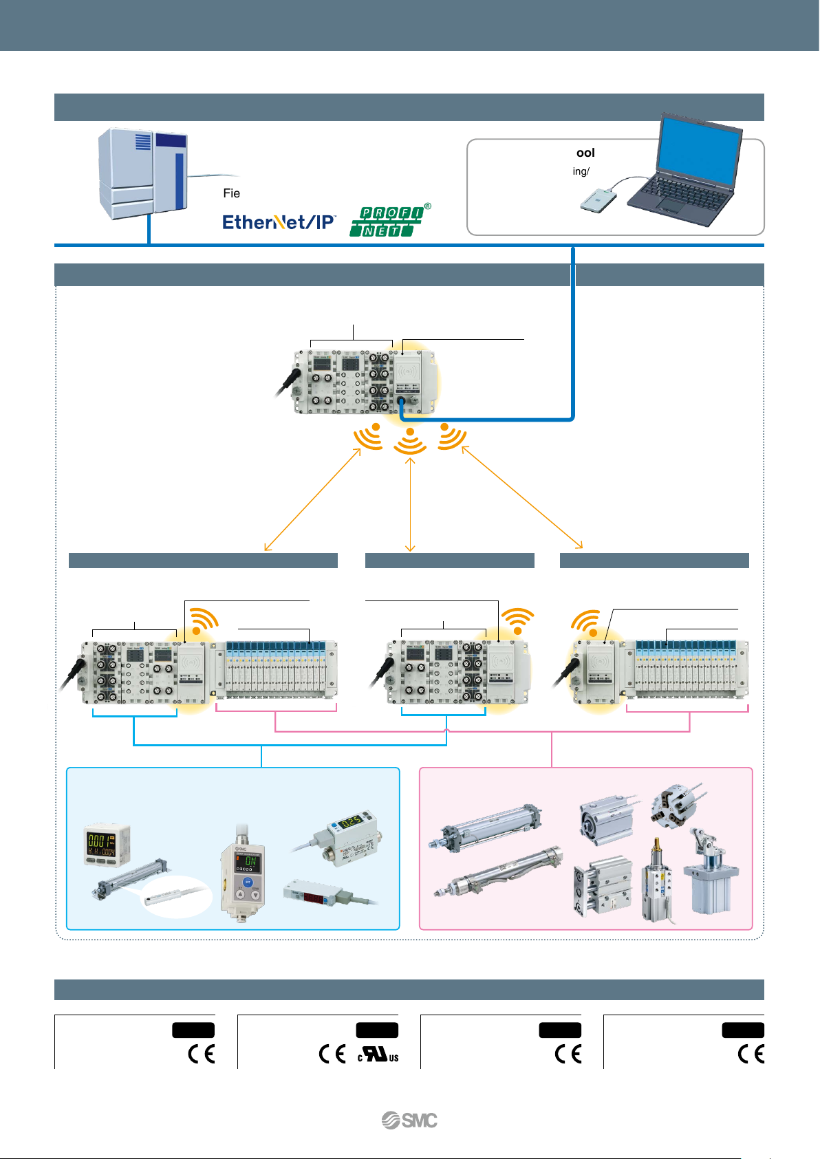
Wireless System EX600-W Series
System Examples
Fieldbus
PLC
Wireless Network
Setting/Monitor tool
Initial setting/monitoring/
pairing are possible.
PC
Combination Example
Remote module No. 1
EX600
I/O unit
p. 7
Refer to the Web Catalog. p. 7
q
Solenoid valve
EX600 I/O unit Base module
Combination Example
Remote module No. 2
p. 7
EX600 I/O unit
Number of I/O points:
Max. 1280 inputs
1280 outputs
w
Combination Example
Remote module No. 3
p. 7
Solenoid valve
e
Other products
Pressure switch, flow switch, auto switch, and other switches
(proximate sensor, photoelectric switch, limit switch, etc.)
Various actuators
Applicable Manifold Solenoid Valves
SY Series SV Series S0700 Series
A
5
IP67 IP67 IP67IP40
®
VQC Series
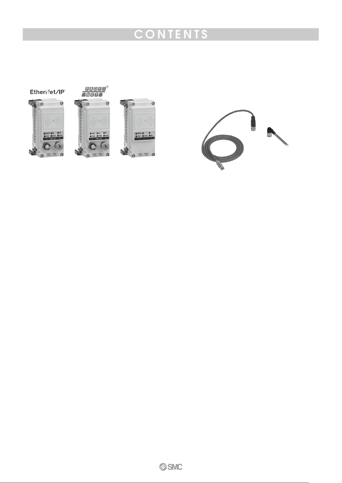
CONTENTS
Wireless System
EX600-W Series
Remote moduleBase module
How to Order
Wireless Unit ······························································· p. 7
Digital Input Unit ·························································· p. 7
Digital Output Unit ······················································· p. 7
Digital Input/Output Unit ·············································· p. 7
Analog Input Unit ························································ p. 8
Analog Output Unit ······················································ p. 8
Analog Input/Output Unit ············································· p. 8
End Plate (D side) ······················································· p. 8
End Plate (U side) ······················································· p. 8
Ordering Example of the Base Module ······················· p. 9
Ordering Example of the Remote Module ·················· p. 9
Specifications
Base Module ····························································· p. 10
Remote Module ························································· p. 12
End Plate (D side) ····················································· p. 12
Dimensions ································································· p. 13
LED Display ································································· p. 15
Accessories
End Plate Bracket
q
Valve Plate
w
Reinforcing Brace
e
Seal Cap
r
Marker (1 sheet, 88 pcs.)
t
Communication Cable with Connector/
y
Communication Connector ··································· p. 19
Power Supply Cable with M12 Connector (A-coded)
u
Power Supply Cable with M12 Connector (B-coded)
u
Power Supply Cable with 7/8 Inch Connector/
i
Power Supply Connector ······································ p. 22
·······························································
·················································
····························································
·················································
······································
······
······
p. 18
p. 18
p. 18
p. 18
p. 19
p. 20
p. 21
Technical Data ············································································································································································ p. 23
Important ···················································································································································································· p. 23
Safety Instructions ···························································································································································· Back cover
A
6
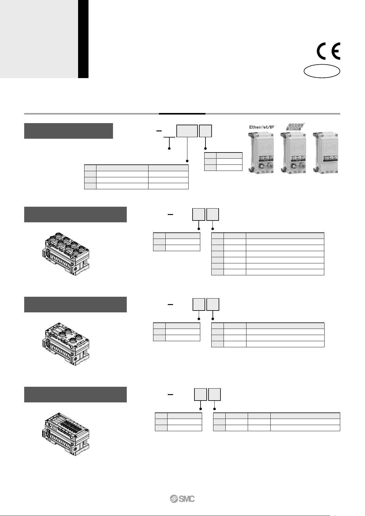
Wireless System
EX600-W Series
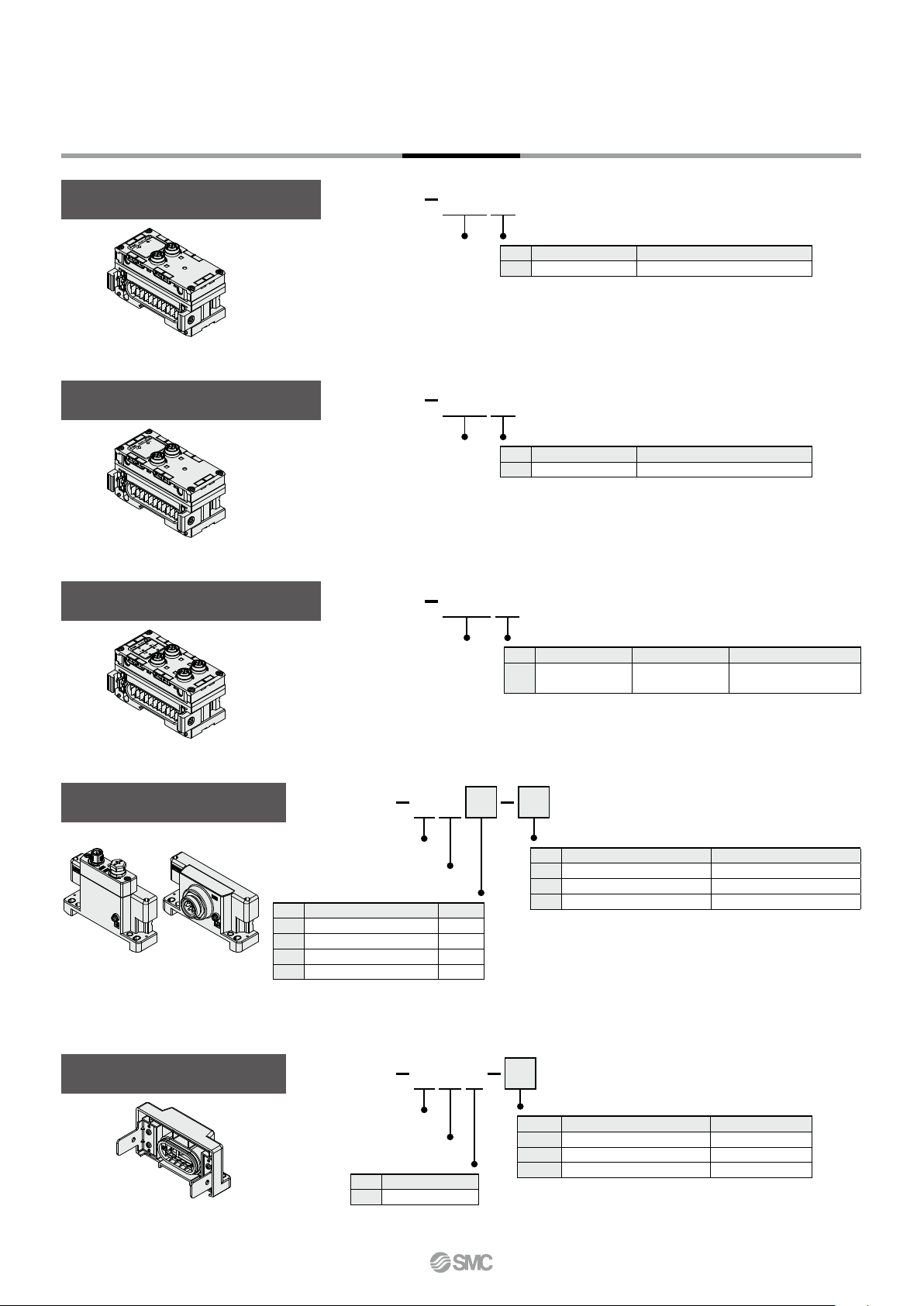
Wireless Unit
Symbol
EN
PN
SV
Digital Input Unit
* For specifications, refer to the Fieldbus
How to Order
ENWEX600 1
Wireless compatible Output type
P
Symbol
1
2
D
Symbol
B
C
C1
D
E
F
Protocol
Specifications Note
Base module For EtherNet/IP™
Base module For PROFINET
Remote module —
DXEX600
Input type Number of inputs and Connector
Symbol
Description
P
N
system EX600 series in the Web
Catalog.
PNP
NPN
Specifications
PNP
NPN
Base module Remote
Number of inputs
8 inputs M12 connector (5 pins) 4 pcs.
8 inputs M8 connector (3 pins) 8 pcs.
8 inputs
16 inputs M12 connector (5 pins) 8 pcs.
16 inputs D-sub connector (25 pins)
16 inputs Spring type terminal block (32 pins)
M8 connector (3 pins) 8 pcs., With open-circuit detection
Connector
RoHS
module
Digital Output Unit
* For specifications, refer to the Fieldbus
system EX600 series in the Web
Catalog.
Digital Input/Output Unit
* For specifications, refer to the Fieldbus
system EX600 series in the Web
Catalog.
DYEX600
Output type Number of outputs and Connector
Symbol
Description
P
N
DMEX600
Input/Output type Number of inputs/outputs and Connector
Symbol
Description
P
N
PNP
NPN
PNP
NPN
P
P
B
Symbol
B
E
F
F
Symbol
E
F
Number of outputs
8 outputs
16 outputs
16 outputs
Number of inputs
8 inputs 8 outputs
8 inputs 8 outputs
M12 connector (5 pins) 4 pcs.
Spring type terminal block (32 pins)
Number of outputs
Connector
D-sub connector (25 pins)
Connector
D-sub connector (25 pins)
Spring type terminal block (32 pins)
A
7
Wireless System
How to Order
EX600-W Series
Analog Input Unit
* For specifications, refer to the Fieldbus
system EX600 series in the Web
Catalog.
Analog Output Unit
* For specifications, refer to the Fieldbus
system EX600 series in the Web
Catalog.
Analog Input/Output Unit
* For specifications, refer to the Fieldbus
system EX600 series in the Web
Catalog.
AXEX600
Analog input
AYEX600
Analog output
AMEX600
Analog input/output
A
Number of input channels and Connector
Symbol
Number of input channels
2 channels M12 connector (5 pins) 2 pcs.
A
Connector
A
Number of output channels and Connector
Symbol
Number of output channels
2 channels M12 connector (5 pins) 2 pcs.
A
Connector
B
Number of input/output channels and Connector
Symbol
Number of input channels Number of output channels
2 channels 2 channels
B
Connector
M12 connector (5 pins)
4 pcs.
End Plate (D side)
For M12 For 7/8 inch
End Plate (U side)
E DEX600 2 2
End plate
End plate mounting position: D side
Power supply connector
Symbol
Power supply connector
M12 (5 pins) B-coded IN
2
7/8 inch (5 pins) IN
3
M12 (4/5 pins) A-coded
4
M12 (4/5 pins) A-coded
5
*1 The pin layout for “4” and “5” pin connector
is different.
Refer to the dimensions on page 14.
Specifications
1
*
IN/OUT
1
*
IN/OUT
E U 1EX600 2
End plate
End plate mounting position: U side
Specifications
Symbol
Specifications
Waterproof cover
1
Mounting method
Symbol
Nil
2
3
* When the end plate (U side) is used, the symbol for the
mounting method must be the same as the D side.
Mounting method
Symbol Description Note
Nil
2
3
* When the end plate (D side) is used, the symbol for the
mounting method must be the same as the U side.
Description Note
Without DIN rail mounting bracket
With DIN rail mounting bracket
With DIN rail mounting bracket
Without DIN rail mounting bracket
With DIN rail mounting bracket
With DIN rail mounting bracket
For SV, S0700, VQC series
For EX600-ED-2
For EX600-ED-3
—
For SY series
—
8
 Loading...