

SMC Networks EX600-SDN2, EX600-SDN1 Maintenance Manual
E
X600-TFL26GB
I
nstallation & Maintenance Manual
Fieldbus System - SI unit
Type EX600-SDN1 / EX600-SDN2
1. Safety Instructions
WARNING
CAUTION
6. Assembly
Do not operate the product beyond the specification range.
Do not use the product for flammable or harmful gases or liquids.
Fire, malfunction, or damage to the product can result.
Please confirm the specifications before use.
Do not operate the product in an environment where flammable
or explosive gases may be present.
Fire or an explosion can result.
The product is not designed to be explosion proof.
Do not disassemble, modify (including change of printed circuit
board) or repair this product.
Injury or failure can result.
The following instructions must be followed when using the
product in an interlocking circuit:
• Provide a multiple interlocking system, such as a mechanical
protection system.
• Check the product regularly to ensure proper operation.
Otherwise malfunction can result, causing an accident.
The following instructions must be followed during maintenance:
• Turn off the power supply.
• Stop the air supply, exhaust the residual pressure and verify
that the air is released to atmosphere before performing
maintenance. Otherwise injury can result.
Do not perform operation or setting with wet hands.
There is a risk of electric shock.
Perform a proper functional check after completing
maintenance.
Stop operation if the equipment does not function properly.
Safety cannot be assured due to unexpected malfunction.
Provide grounding to assure the safety and noise immunity of
the fieldbus system.
Individual grounding should be provided close to the product with an
earth cable as short as possible.
When handling, assembling and replacing the unit:
• Do not touch any sharp metal parts of the connector or plug.
• Do not apply excessive force to the unit.
The connecting portions of the unit are firmly joined with seals.
• When joining units, take care not to get fingers caught
between units.
Injury can result.
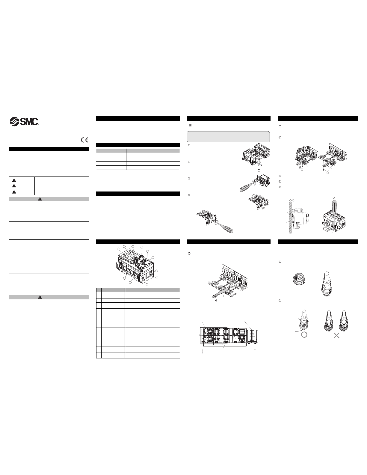
5. Names / Functions of individual Parts
No.
Part
Usage
3
Indication cover set
screw
Loosen to open the indication cover.
5 Marker groove Groove to mount an indication marker.
10
Connector for unit
(plug)
Conveys the signals and power supplies to the
adjacent unit.
11
Connector (BUS
IN) (plug)
Connector for FieldBus input. BUS IN and
BUS OUT are connected inside the unit.
4
Connector (BUS
OUT) (socket)
Connector for FieldBus output. BUS IN and
BUS OUT are connected inside the unit.
6
Connector
(for handheld terminal)
(socket)
Connector to connect a handheld terminal.
7
Valve plate mounting
holes
Holes for fixing the valve plate.
8
Valve plate mounting
groove
Groove for mounting the valve plate.
1
Status
indication LED
2 Indication cover
Open to gain access to the setting switches.
Indicates the unit status. (Refer to the “Trouble
Shooting” section for further details.)
9 Joint bracket
Joint bracket to join the adjacent unit, fixed with
attached screws.
1
11
2
3
4
5
6
7
8
9
10
Composing the unit as a manifold.
: If the unit was purchased as a manifold, the work described in this
section is not necessary.
Note
Be sure to turn off the power when carrying out the work to
compose the unit as a manifold.
Connect a unit to the end plate. Digital input
units, digital output units and analog units
can be connected in any order.
(Tightening torque: 1.5 to 1.6 Nm)
Connection of SI unit
Connect the SI unit after connecting all of the
required I/O units together.
The connection procedure is the same as the previous step .
Mounting the valve plate
Mount the valve plate to the manifold valve
with valve fixing screws.
(Tightening torque: 0.6 to 0.7 Nm)
Connect the SI unit to the manifold valves.
Insert the valve plate into the valve plate mounting
groove at the side of the SI unit.
Fix using the valve plate fixing screws.
(Tightening torque:0.7 to 0.8 Nm)
7. Installation
<Installation method>
Direct mounting
When joining six or more units, fix the middle part of the complete
EX600 unit with an intermediate reinforcing brace (EX600-ZMB1) before
mounting (Refer to the figure below), using 2xM4 screws. (Tightening
torque: 0.7 to 0.8 Nm)
Fix and tighten the end plates at one end of the unit as shown in the
figure below. (Tightening torque: 0.7 to 0.8 Nm)
Fix the end plate at the valve side while referring to the operation
manual of the corresponding manifold valve.
Intermediate reinforcing brace
(EX600-ZMB1)
2xM4 screws (tightening torque: 0.7 to 0.8 Nm)
End plate
Manifold valve
117 0.2
90 0.2
Intermediate reinforcing brace
2xM4 screws
23.5
47xn
5.5
826
8
47
47xm
(Tolerance: 0.2 mm)
<DIN rail mounting>
When joining six or more units, fix the middle part of the complete
EX600 unit with an intermediate reinforcing brace (EX600-ZMB2)
before mounting, using 2xM4 screws. (Tightening torque: 0.7 to 0.8
Nm)
Mount the end plate bracket (EX600-ZMA2) to the end plate, using
2xM4 screws. (Tightening torque: 0.7 to 0.8 Nm)
Hook the DIN rail mounting groove to the DIN rail. (See the figure
below.)
Press the manifold using its side hooked to the DIN rail as a fulcrum
until the manifold is locked.
Fix the manifold by tightening the DIN rail fixing screws of the
EX600-ZMA2. (Tightening torque: 0.7 to 0.8 Nm)
The tightening torque at the valve side depends on the valve type.
2
End plate bracket
(EX600-ZMA2)
1
I
ntermediate reinforcing
b
race (EX600-ZMB2)
DIN rail
Fulcrum
4
3
,
5
End plate bracket
(EX600-ZMA2)
Mark at cable end
Mark on the unit
Projected
portion
8. Wiring
2. How to Order
3. Specifications
4. Outline dimensions(mm)
7. Installation (continued)
<SPEEDCON Wiring method>
The M12 connector can be mated with a SPEEDCON
connector.
Set the projected portion of the cable connector metal ring (plug /
socket) to the mark at cable end.
Push the connector straight to insert it into the receptacle of the unit.
If inserted without aligning the mark, the connector will not mate with
the receptacle.
Refer to the catalogue or operation manual for this product.
Refer to the catalogue or operation manual for this product to get
information about product specifications in detail.
Refer to the catalogue or operation manual for this product.
These safety instructions are intended to prevent hazardous situations
and/or equipment damage.
These instructions indicate the level of potential hazard by label of
"DANGER", "WARNING"or "CAUTION", followed by important safety
information which must be carefully followed.
To ensure safety of personnel and equipment the safety instructions in
this manual and the product catalogue must be observed, along with
other relevant safety practices.
If instructions are not followed there is a
possibility of serious injury or loss of life.
If instructions are not followed there is a
possibility of injury or equipment damage.
In extreme conditions, there is a possible result
of serious injury or loss of life.
DANGER
WARNING
CAUTION
Item Specifications
Enclosure IP67 (Combination with valve manifold)
Environment Pollution degree 2 (UL508)
Operating temperature -10 to +50 °C
Ambient humidity 35 to 85%RH (No dew condensation)
E
X600-TFL26GB
8
. Wiring (continued)
Wiring connection with handheld terminal
Refer to “Handheld Terminal Operation Manual” for the connection with
the handheld terminal.
12
34
5
Note
Be sure to place a seal cap on any unused connectors. Placing the
seal cap appropriately enables the unit to achieve IP67 protection.
BUS IN
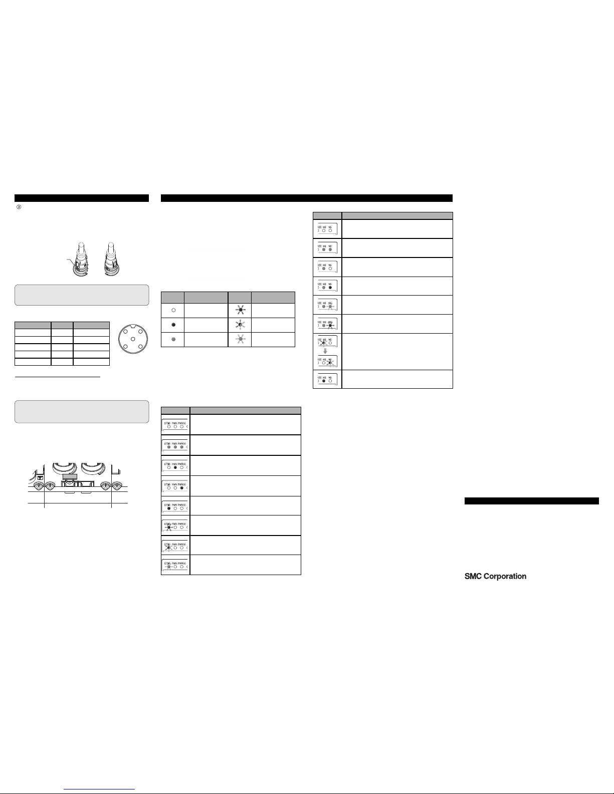
Status indication LED (see figure below) displays the power
supply status and communication status. These can be checked
a
ccording to the following:
<Display status>
Indicator
symbol
Status
Indicator
symbol
Status
OFF Flashing Red
Red Light ON
Flashing Red and
Green alternately
Green Light ON Flashing Green
9. Trouble Shooting
<Common for SI Units>
Indicator Status
Power for control/input is OFF.
Unit is operating normally.
Abnormal power voltage for control/input. Check the power
supply and adjust or replace it.
Abnormal power voltage for output. Check the power
supply and adjust or replace it.
Component failure inside SI unit.
When ST(M) indicator is red, stop using the product and
contact SMC.
•Valve is in short circuit or open circuit.
•Valve ON/OFF counter has exceeded the set value.
Communication error between units, or configuration memory
error.
Check the connection between units, or the unit configuration.
Error diagnostics detected the error of a unit other than the
SI unit.
<
SI Unit - DeviceNet
TM
>
Indicator Status
Power is OFF.
Communicating normally.
Checking node address duplication.
Critical communication error.
Check the node Address or Data Rate etc.
Connection cannot be established.
Non-critical communication error.
Check the Data Rate etc.
Performing self diagnostics at start up.
Component failure inside SI unit. Stop using the product
and contact SMC.
Note
Be sure to connect a termination resistor at both ends of the
DeviceNetTMtrunk line.
Turn-lock mechanism
of the connector
Signal name Pin No. Wire colour
DRAIN 1 Drain
V+ 2 Red
V- 3 Black
CAN H 4 White
CAN L 5 Blue
Turn the connector clockwise. It stops when turned 1/4 turn.Turn it
further. When the connector is turned 1/2 turn from the original
position, the projected portion is set at the diagonal position to the
mark and the turn is completed. Check that the connector is
securely locked.
If the connector is turned excessively, it will become difficult to
remove.
<Mounting the marker>
Mount the marker (EX600-ZT1) into the marker groove as required.
<Connection>
10. Contact
AUSTRIA (43) 2262 62280 NETHERLANDS (31) 20 531 8888
BELGIUM (32) 3 355 1464 NORWAY (47) 67 12 90 20
CZECH REP. (420) 541 424 611 POLAND (48) 22 211 9600
DENMARK (45) 7025 2900 PORTUGAL (351) 21 471 1880
FINLAND (358) 207 513513 SLOVAKIA (421) 2 444 56725
FRANCE (33) 1 6476 1000 SLOVENIA (386) 73 885 412
GERMANY (49) 6103 4020 SPAIN (34) 945 184 100
GREECE (30) 210 271 7265 SWEDEN (46) 8 603 1200
HUNGARY (36) 23 511 390 SWITZERLAND (41) 52 396 3131
IRELAND (353) 1 403 9000 UNITED KINGDOM (44) 1908 563888
ITALY (39) 02 92711
URL http://www.smcworld.com (Global) http://www.smceu.com (Europe)
Specifications are subject to change without prior notice from the manufacturer.
© 2009 SMC Corporation All Rights Reserved.
 Loading...