

Page 1
No.EX※※-OML0011-C
PRODUCT NAME
Fieldbus Device
Handheld Terminal
MODEL / Series / Product Number
EX600-HT1A
Page 2

-1-
No.EX※※-OML0011-C
Table of Contents
Safety Instructions 2
Model Indication and How to Order 8
Names and Functions of Product 8
Definition and terminology 9
Mounting and Installation 10
Precautions before mounting 10
Wiring 11
Setting and Adjustment 12
Basic operation 12
Mode selection 13
1. I/O monitor 15
2. Diagnosis Data 24
3. Sys. Configuration 27
4. Parameter Setting 33
5. Terminal Setting 47
Troubleshooting 50
Parameter Setting 52
Specifications 53
Dimensions 53
Page 3
-2-
No.EX※※-OML0011-C
Safety Instructions
These safety instructions are intended to prevent hazardous situations and/or equipment damage.
These instructions indicate the level of potential hazard with the labels of "Caution", "Warning" or "Danger".
They are all important notes for safety and must be followed in addition to International Standards
(ISO/IEC)*1), and other safety regulations.
*1) ISO 4414: Pneumatic fluid power -- General rules relating to systems.
ISO 4413: Hydraulic fluid power -- General rules relating to systems.
IEC 60204-1: Safety of machinery -- Electrical equipment of machines .(Part 1: General requirements)
ISO 10218: Manipulating industrial robots -Safety.
etc.
Caution
Caution indicates a hazard with a low level of risk which, if not avoided, could
result in minor or moderate injury.
Warning
Warning indicates a hazard with a medium level of risk which, if not avoided,
could result in death or serious injury.
Danger
Danger indicates a hazard with a high level of risk which, if not avoided, will
result in death or serious injury.
Warning
1. The compatibility of the product is the responsibility of the person who designs the
equipment or decides its specifications.
Since the product specified here is used under various operating conditions, its compatibility with specific
equipment must be decided by the person who designs the equipment or decides its specifications
based on necessary analysis and test results.
The expected performance and safety assurance of the equipment will be the responsibility of the
person who has determined its compatibility with the product.
This person should also continuously review all specifications of the product referring to its latest catalog
information, with a view to giving due consideration to any possibility of equipment failure when
configuring the equipment.
2. Only personnel with appropriate training should operate machinery and equipment.
The product specified here may become unsafe if handled incorrectly.
The assembly, operation and maintenance of machines or equipment including our products must be
performed by an operator who is appropriately trained and experienced.
3. Do not service or attempt to remove product and machinery/equipment until safety is
confirmed.
1. The inspection and maintenance of machinery/equipment should only be performed after measures to
prevent falling or runaway of the driven objects have been confirmed.
2. When the product is to be removed, confirm that the safety measures as mentioned above are
implemented and the power from any appropriate source is cut, and read and understand the specific
product precautions of all relevant products carefully.
3. Before machinery/equipment is restarted, take measures to prevent unexpected operation and malfunction.
4. Contact SMC beforehand and take special consideration of safety measures if the
product is to be used in any of the following conditions.
1. Conditions and environments outside of the given specifications, or use outdoors or in a place
exposed to direct sunlight.
2. Installation on equipment in conjunction with atomic energy, railways, air navigation, space, shipping,
vehicles, military, medical treatment, combustion and recreation, or equipment in contact with food and
beverages, emergency stop circuits, clutch and brake circuits in press applications, safety equipment or
other applications unsuitable for the standard specifications described in the product catalog.
3. An application which could have negative effects on people, property, or animals requiring special
safety analysis.
4. Use in an interlock circuit, which requires the provision of double interlock for possible failure by using
a mechanical protective function, and periodical checks to confirm proper operation.
Page 4
-3-
No.EX※※-OML0011-C
Safety Instructions
Caution
1.The product is provided for use in manufacturing industries.
The product herein described is basically provided for peaceful use in manufacturing industries.
If considering using the product in other industries, consult SMC beforehand and exchange
specifications or a contract if necessary.
If anything is unclear, contact your nearest sales branch.
Limited warranty and Disclaimer/Compliance Requirements
The product used is subject to the following "Limited warranty and Disclaimer" and "Compliance
Requirements".
Read and accept them before using the product.
Limited warranty and Disclaimer
1. The warranty period of the product is 1 year in service or 1.5 years after the product is
delivered, whichever is first.2)
Also, the product may have specified durability, running distance or replacement parts.
Please consult your nearest sales branch.
2. For any failure or damage reported within the warranty period which is clearly our
responsibility, a replacement product or necessary parts will be provided.
This limited warranty applies only to our product independently, and not to any other
damage incurred due to the failure of the product.
3. Prior to using SMC products, please read and understand the warranty terms and
disclaimers noted in the specified catalog for the particular products.
2) Vacuum pads are excluded from this 1 year warranty.
A vacuum pad is a consumable part, so it is warranted for a year after it is delivered.
Also, even within the warranty period, the wear of a product due to the use of the
vacuum pad or failure due to the deterioration of rubber material are not covered by the
limited warranty.
Compliance Requirements
1. The use of SMC products with production equipment for the manufacture of weapons of
mass destruction (WMD) or any other weapon is strictly prohibited.
2. The exports of SMC products or technology from one country to another are governed by
the relevant security laws and regulation of the countries involved in the transaction. Prior
to the shipment of a SMC product to another country, assure that all local rules governing
that export are known and followed.
Page 5
-4-
No.EX※※-OML0011-C
Operator
This operation manual is intended for those who have knowledge of machinery using pneumatic
equipment, and have sufficient knowledge of assembly, operation and maintenance of such
equipment. Only those persons are allowed to perform assembly, operation and maintenance.
Read and understand this operation manual carefully before assembling, operating or providing
maintenance to the product.
■Safety Instructions
Warning
■Do not disassemble, modify (including changing the printed circuit board) or repair.
An injury or failure can result.
■Do not operate or set with wet hands.
This may lead to an electric shock.
■Do not operate the product outside of the specifications.
Do not use for flammable or harmful fluids.
Fire, malfunction, or damage to the product can result.
Verify the specifications before use.
■Do not operate in an atmosphere containing flammable or explosive gases.
Fire or an explosion can result.
This product is not designed to be explosion proof.
■Do not press the display.
This may cause injury and damage to the LCD display.
■If using the product in an interlocking circuit:
•Provide a double interlocking system, for example a mechanical system.
•Check the product regularly for proper operation.
Otherwise malfunction can result, causing an accident.
■The following instructions must be followed during maintenance:
•Turn off the power supply.
•Stop the air supply, exhaust the residual pressure and verify that the air is released before performing
maintenance.
Otherwise an injury can result.
■The forced input/output function is used to change the signal status forcibly. When operating this function,
be sure to check the safety of the surrounding and installation.
Otherwise, injury or equipment damage could result.
■Incorrect setting of parameters can cause malfunction. Be sure to check the settings before use.
Otherwise, injury or equipment damage could result.
Page 6
-5-
No.EX※※-OML0011-C
Caution
■After maintenance is complete, perform appropriate functional inspections.
Stop operation if the equipment does not function properly.
Safety cannot be assured in the case of unexpected malfunction.
■Changing select Hold/Clear function mode switches the operation of I/O signals in an emergency. Carry
out settings paying attention to safety.
Otherwise, injury or equipment damage could result.
■NOTE
○Follow the instructions given below when designing, selecting and handling the product.
●The instructions on design and selection (installation, wiring, environment, adjustment,
operation, maintenance, etc.) described below must also be followed.
Product specifications
•The direct current power supply to combine should be UL 1310 Class2 power supply when conformity to
UL is necessary.
•Use the specified voltage.
Otherwise failure or malfunction can result.
•Do not remove any nameplates or labels.
This can lead to incorrect maintenance, or misreading of the operation manual, which could cause damage or
malfunction to the product.
It may also result in non-conformity to safety standards.
•Beware of inrush current when the power supply is turned on.
Some connected loads can apply an initial charge current which will activate the over current protection function,
causing the unit to malfunction.
Page 7

-6-
No.EX※※-OML0011-C
●Product handling
Installation
•Do not drop, hit or apply excessive shock to the SI unit.
Otherwise damage to the product can result, causing malfunction.
Wiring
•Avoid repeatedly bending or stretching the cables, or placing heavy load on them.
Repetitive bending stress or tensile stress can cause breakage of the cable.
•Wire correctly.
Incorrect wiring can break the product.
•Do not route wires and cables together with power or high voltage cables.
Otherwise the SI unit and/or input or output device can malfunction due to interference of noise and surge voltage
from power and high voltage cables to the signal line.
Route the wires (piping) of the SI unit and/or input or output device separately from power or high voltage cables.
•Confirm proper insulation of wiring.
Poor insulation (interference from another circuit, poor insulation between terminals, etc.) can lead to excess
voltage or current being applied to the product, causing damage.
•Take appropriate measures against noise, such as using a noise filter, when the Fieldbus system is
incorporated into equipment.
Otherwise noise can cause malfunction.
Environment
•Do not use the product in area that is exposed to corrosive gases, chemicals, sea water, water or steam.
Otherwise failure or malfunction can result.
•Do not use in an area where surges are generated.
If there is equipment generating large surge near the unit (magnetic type lifter, high frequency inductive furnace,
welding machine, motor, etc.), this can cause deterioration of the internal circuitry element of the unit or result in
damage. Take measures against the surge sources, and prevent the lines from coming into close contact.
•The product is CE marked, but not immune to lightning strikes. Take measures against lightning strikes
in the system.
•Prevent foreign matter such as dust or wire debris from getting inside the product.
•Mount the product in a place that is not exposed to vibration or impact.
Otherwise failure or malfunction can result.
•Do not use the product in an environment that is exposed to temperature cycle.
Heat cycles other than ordinary changes in temperature can adversely affect the inside of the product.
•Do not expose the product to direct sunlight.
If using in a location directly exposed to sunlight, shade the product from the sunlight.
Otherwise failure or malfunction can result.
•Keep within the specified ambient temperature range.
Otherwise malfunction can result.
•Do not operate close to a heat source, or in a location exposed to radiant heat.
Otherwise malfunction can result.
Page 8

-7-
No.EX※※-OML0011-C
Adjustment and Operation
•Perform settings suitable for the operating conditions.
Incorrect setting can cause operation failure.
•Please refer to the PLC manufacturer's manual etc. for details of programming and addresses.
For the PLC protocol and programming refer to the relevant manufacturer's documentation.
Maintenance
•Turn off the power supply, stop the supplied air, exhaust the residual pressure and verify the release of
air before performing maintenance.
There is a risk of unexpected malfunction.
•Perform regular maintenance and inspections.
There is a risk of unexpected malfunction.
•After maintenance is complete, perform appropriate functional inspections.
Stop operation if the equipment does not function properly.
Otherwise safety is not assured due to an unexpected malfunction or incorrect operation.
•Do not use solvents such as benzene, thinner etc. to clean each unit.
They could damage the surface of the body and erase the markings on the body.
Use a soft cloth to remove stains.
For heavy stains, use a cloth soaked with diluted neutral detergent and fully squeezed, then wipe up the stains
again with a dry cloth.
Page 9
-8-
No.EX※※-OML0011-C
Model Indication and How to Order
EX600–HT1A–
Length of Cable for Handheld Terminal
Symbol
Content
Nil
Without cable
1
1 m 3 3 m
Option
Name
Product number
Handheld Terminal cable 1m
EX600-AC010-1
Handheld Terminal cable 3m
EX600-AC030-1
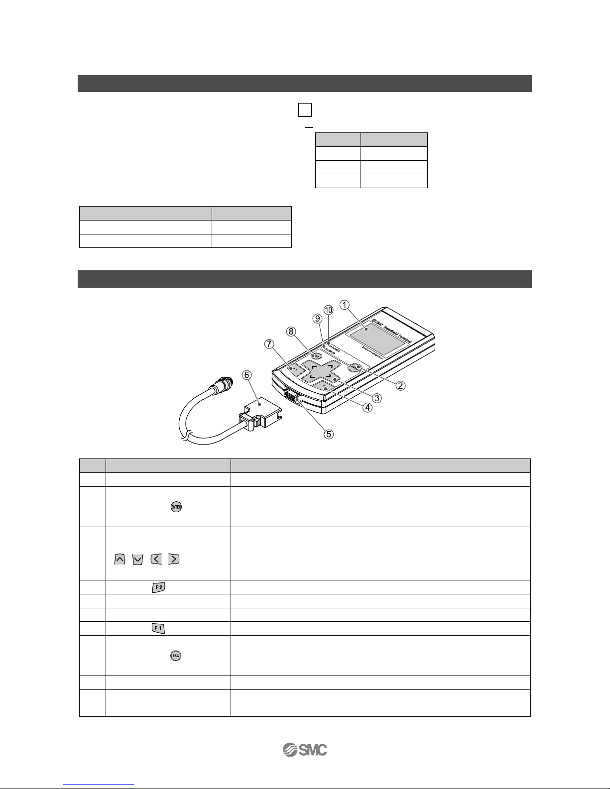
Names and Functions of Product
No.
Description
Function
1
LCD display
Displays operation items and information about the unit.
2
ENTER button ( )
In the selecting screen, this button shifts the screen to the item that has been
selected.
In the setting screen, it registers what has been set on that screen so far.
3
Cursor direction buttons
( , , , )
Moves the cursor of the LCD display up, down, left and right.
In the selection screen, move the cursor up, down, left and right to select the
item.
In the setting screen, increase/decrease or turn ON/OFF the set value.
4
F2 button ( )
Functions according to the display or instructions on the screen.
5
Connecter
Connects the Cable for Handheld Terminal.
6
Cable for Handheld Terminal
Connects the SI unit and Handheld Terminal.
7
F1 button ( )
Functions according to the display or instructions on the screen.
8
Escape button ( )
In the selection screen, this button will return the screen to the previous page.
In the setting screen, it cancels what has been set so far on that screen, and
returns the screen to the previous page.
9
ERROR display LED
The LED turns ON when a diagnostic error occurs.
10
POWER display LED
The LED turns ON when the EX600 SI unit is connected and the power is
supplied.
: Refer to Troubleshooting (page 50) for the further details of countermeasures.
Page 10
-9-
No.EX※※-OML0011-C
■Definition and terminology
Terminology
Definition
C
Channel number
Sequential number given to each input and output on an individual module
(Refer to the manual of each unit for the arrangement of the channels).
Number given for each unit’s input and output point. Please refer to the manual
of each unit for the arrangement of the channel.
D
Diagnostic
Function of EX600 to self monitor if error has occurred or configuration has
changed.
E
Error log
A chronological list of previous errors occurred. A maximum of 30 errors can be
recorded.
Enforced output function
A function to drive an output signal forcibly, ignoring control data from the PLC.
Enforced input function
A function to specify an input signal forcibly, ignoring signal from the connected
sensor.
H
Handheld Terminal
(H.T.)
Connected to the dedicated connector of the SI unit to adjust the internal
parameters, monitor the status of all input and output signals, and turn on input
and output forcedly.
M
Manifold number
The number of the EX600 manifold that includes the selected unit. This function
will be utilized in the future. Until then, the current state will always be 0.
O
ON/OFF counter
Counter of number of times when output or input changes from OFF to ON.
P
Parameter copy function
Function to copy selected unit parameter setting to all units in the manifold or
also to copy channel parameter to all channels in the same unit.
Power save
The LCD’s backlight is turned off to save power.
S
SI unit
Abbreviation of serial interface unit. A unit connected to a PLC to communicate
input and output data.
T
Tag
An electronic, 4 character name that can be given to units. This name can help
with unit management. Electronic name can be given to manage units. Each
unit can be given maximum of 4 digits of character.
U
Unit number
Selected unit’s number. Unit connected right of the end plate becomes unit
number 0.
Page 11
-10-
No.EX※※-OML0011-C
Mounting and Installation
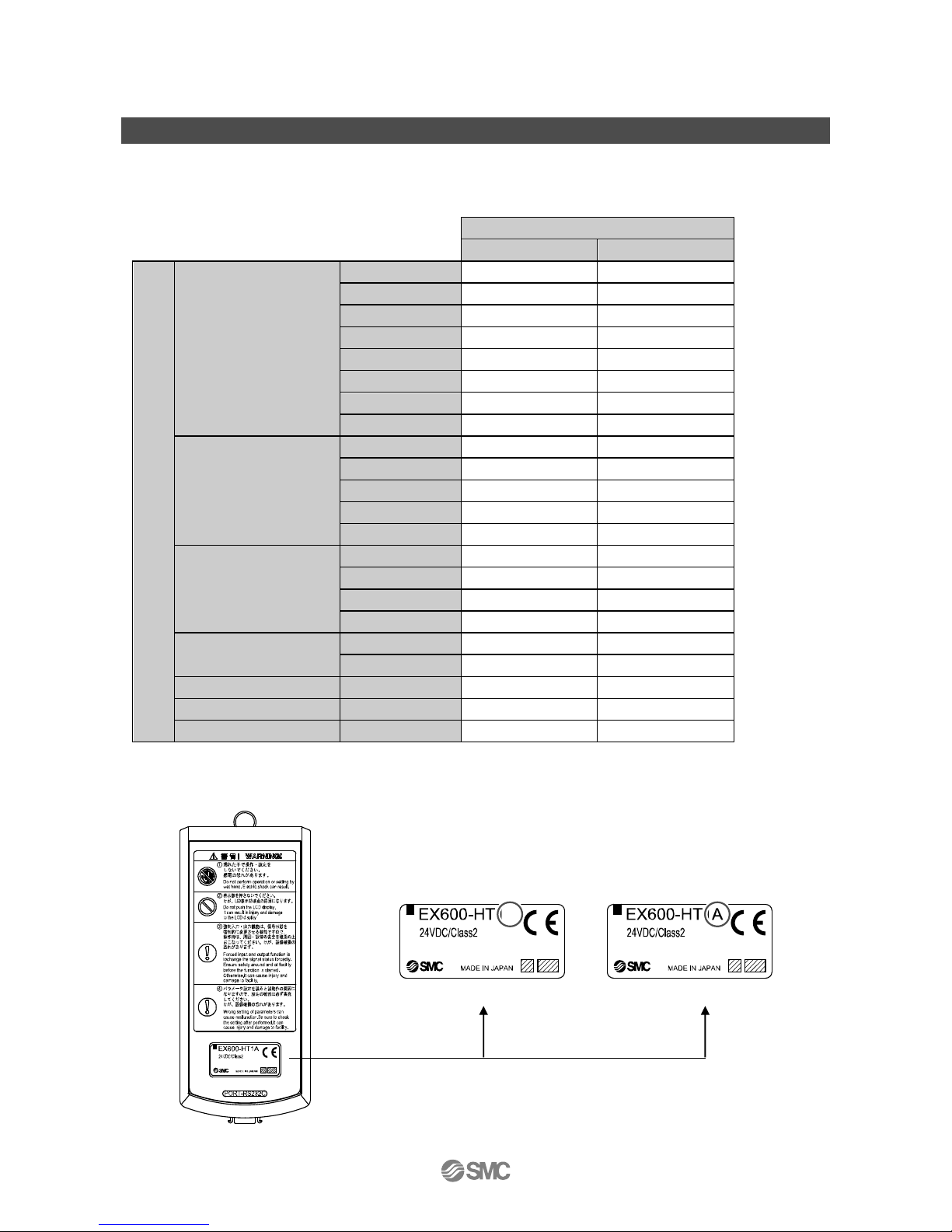
■Precautions before mounting
The units that can be connected vary depending on the Handheld Terminal product number.
Check the applicable unit type before mounting the unit.
Units that can be assembled
Product number of the Handheld Terminal
EX600-HT1
EX600-HT1A
Product nunber
SI unit
EX600-SPR□ ○ ○
EX600-SPR□A
○
○
EX600-SDN□ ○ ○
EX600-SDN□A
○
○
EX600-SMJ□ ○ ○
EX600-SEN□ × ○
EX600-SEC□ × ○
EX600-SPN□ × ○
Digital input unit
EX600-DX□B ○ ○
EX600-DX□C□
○
○
EX600-DX□D ○ ○
EX600-DX□E × ○
EX600-DX□F × ○
Disital output unit
EX600-DY□B ○ ○
EX600-DY□E × ○
EX600-DY□E1
×
○
EX600-DY□F × ○
Digital I/O unit
EX600-DM□E × ○
EX600-DM□F × ○
Analog input unit
EX600-AXA ○ ○
Analog output unit
EX600-AYA × ○
Analog I/O unit
EX600-AMB × ○
1: EX600-HT1 cannot recognize EX600-D□□E, EX600-D□□F, Ex600-AYA and EX600-AMB.
Find the product number of the Handheld Terminal referring to the label shown in the figure below.
•EX600-HT1A
•EX600-HT1A
Page 12
-11-
No.EX※※-OML0011-C
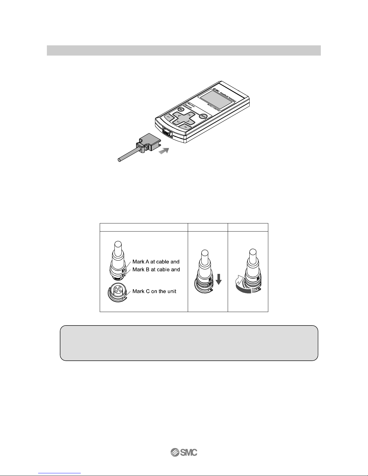
■Wiring
Insert the cable for Handheld Terminal into the connector, with the connectors aligned in the same direction.
•Connect the M12 connector on the Handheld Terminal cable into the connector (PCI) of the SI unit.
(1)Align the mark A on the metal bracket of the cable side connector (plug/socket) with the mark B.
(2)Align the mark C on the unit and insert the connector into the unit vertically.
If they are not aligned, the connector cannot be joined properly.
(3)When the mark B of the connector has been turned 180 degrees (1/2 turn), wiring is completed. Confirm
that the connection is not loose. If turned too far, it will become hard to remove the connector.
(1)
(2)
(3)
●Precautions for handling
•If there is any foreign matter or water droplets stuck to or inside the SI unit or Handheld Terminal,
clean and remove them before connecting the cable. If the SI unit is installed in an environment
where residual liquid is accumulated, use a soft cloth to gently remove it.
Page 13
-12-
No.EX※※-OML0011-C
Setting and Adjustment
■Basic operation
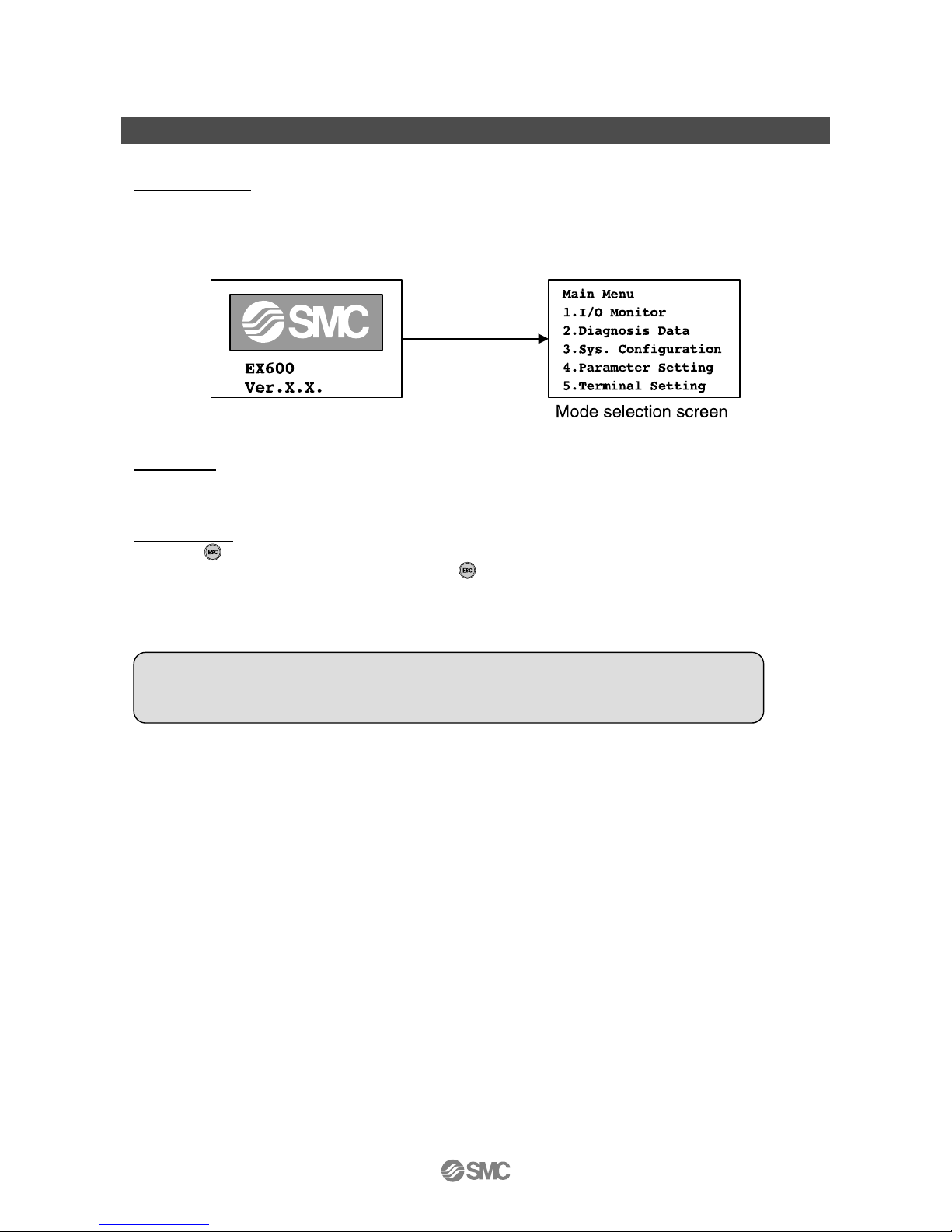
Supply of Power
(1)When the SI Unit is connected to the cable, the power is supplied to the Handheld Terminal.
(2)The POWER LED (green) turns ON, and the start-up screen is displayed on the LCD display.
(3)Then the screen shifts to the mode selection screen.
(4)The operation is explained on the following pages.
Power OFF
During Main Menu screen, remove the cable connected to the SI unit
Power Saving
When the button is pressed for 2 seconds or longer while the power supply is ON, the display on the
display on the LCD screen disappears. Press the button to reset it.
: Refer to Terminal Setting (page 47) for the details of setting.
●Precautions for handling
•The connector should be removed only when the mode selection screen is displayed.
Failure, accident and malfunction can result.
Page 14
-13-
No.EX※※-OML0011-C
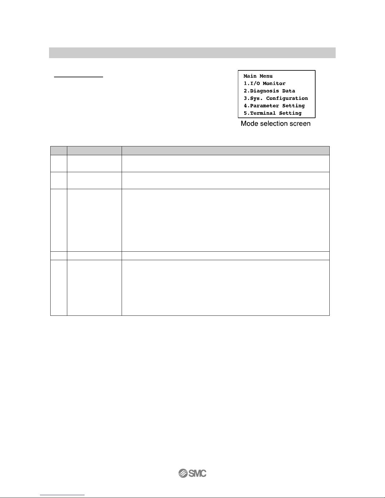
■Mode selection
Outline of modes
The Handheld Terminal has five modes.
Each mode further consists of detailed mode levels,
which can be used to set and check each type of data.
No.
Mode
Outline
1
I/O Monitor
Displays the unit input and output status and performs forced input and output.
(Refer to page 15)
2
Diagnosis Data
Displays the input and output status of the unit, detailed error contents and error log.
(Refer to page 24)
3
Sys. Configuration
Sets the sysytem operation as follows. (Refer to page 27)
1. Edits the tag name of each unit.
2. Update the unit structre memorry infomaion.
3. Select the Hold/Clear function to be set either by the SI unit switches, or by the
Handheld Terminal.
4. Clears the ON/OFF counter valve of each unit.
5. Resets the parameters of each unit to the default values.
6. Clear all error logs.
4
Parameter Setting
Sets various parameters. (Refer to page 33)
5
Terminal Setting
Sets the operation of the Handheld Terminal as follows. (Refer to page 47)
1. Sets the contrast of the LCD display screen.
2. Sets the brightness of the LCD display screen.
3. Sets the volume of the click sound when buttons are pressed.
4. Sets the time before entering Power Save mode when no operation is performed.
5. Returns the settings 1 to 4 above to the default values.
6. Change the password.
Page 15
-14-
No.EX※※-OML0011-C
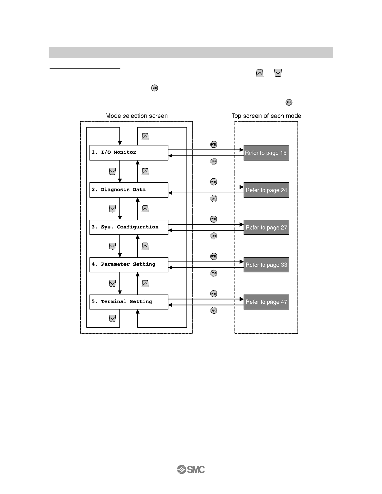
Follow of mode selection
1. In the mode selection screen, move the cursor up and down by pressing the or button and select
the next mode.
2. When the mode is selected and the button is pressed, the screen shifts to the top screen of each
mode.
3. To return to the mode selection screen from the top screen of the each mode, press the button.
: When each button is pressed, the mode shifts in the direction indicated by the arrow.
Page 16
-15-
No.EX※※-OML0011-C
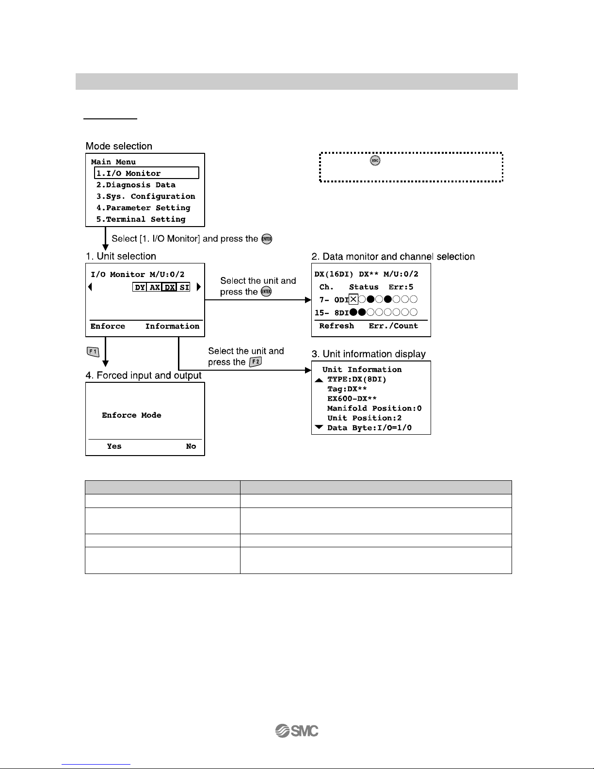
■1. I/O monitor
Mode levels
The I/O monitor mode is composed as shown in the diagram below.
Mode
Outline
1. Unit Selection
Select the unit to perform the operation from 2 to 4. (Refer to page 16)
2. Data monitor and channel selection
Input and output status of the unit, error information, and ON/OFF count
values are displayed. (Refer to page 17)
3. Unit information display
The information of the unit selected is displayed. (Refer to page 19)
4. Forced input and output
The input and output signal of the unit is forcibly operated with the
Handheld Terminal. (Refer to page 20)
Press the button in each screen to
return to the previous screen.
Page 17
-16-
No.EX※※-OML0011-C
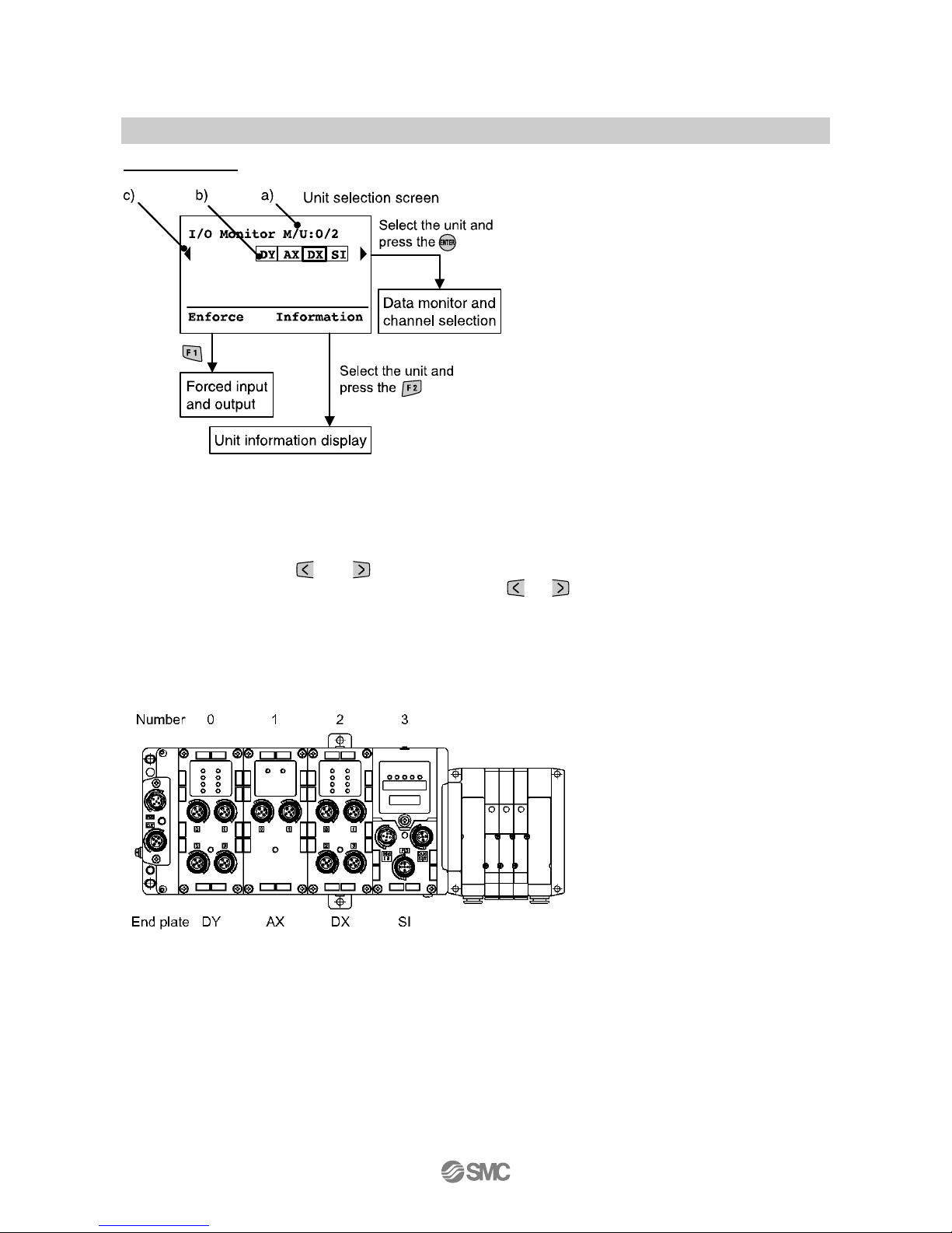
1. Unit selection
♦Explanation of screen
a) Manifold number
1
/Unit number
2
Displays the manifold number and unit number of the unit selected.
b) Unit symbol (Refer to page 52)
Select the unit with the and buttons.
c) The next unit structure will be displayed by pressing the or buttons (in case of 8 units or more).
1: The manifold number is function which will be used for extension in the future, so “0” is always display.
2: The unit positioned closest to the endplate is numbered as 0. An example is shown below.
•Example of unit number
Page 18

-17-
No.EX※※-OML0011-C
2. Data monitor and channel selection
•For Digital unit
♦Explanation of screen
a) Displayed unit symbol (Refer to page 52)
b) Tag name (Refer to page 28)
c) Manifold number/Unit number (Refer to page 16)
d) Channel number
e) Error code (Refer to page 51)
f) Channel selection cursor
Select the channel with the , , and buttons.
g) Other channels are displayed with the and buttons.
h) Display of channel status
○: OFF ●: ON ×: Error
i) The next error is displayed with the and buttons.
j) Error code details (Refer to page 51)
k) Counter value (SI, DX, DY, DM only)
The count ON/OFF counter values are displayed.
: The update interval of the ON/OFF counter value depends on the unit. When the power source is turned on, counting starts from the
counter value that was present at the time the power was switched OFF. The memory update interval of the units is as shown below.
•SI Unit
Updates from valve output 0 every 30 seconds.
•Digital unit (DX, DY, DM)
Updates for all channels every one hour.
Page 19

-18-
No.EX※※-OML0011-C
•For Analog unit
♦Explanation of screen
a) Displayed unit symbol (Refer to page 52)
b) Tag name (Refer to page 28)
c) Manifold number/Unit number (Refer to page 16)
d) Channel number
e) Error code (Refer to page 51)
f) Channel selection cursor
Select the channel with the and buttons.
g) Other channels are displayed with the and buttons.
h) Display of channel status
•When analog data format is set to other than Scaled.
±□□□mA: Input or output value (Current range)
±□□□V : Input or output value (Voltage range)
× : Error
•When analog data format is set to Scaled.
±□□•••: Input or output value
×: Error
The or button is pressed, the display changes as shown below.
±□□□mA: Input or output value (Current range)
±□□□V: Input or output value (Voltage range)
i) The next error is displayed with the and buttons.
j) Error code details (Refer to page 51)
Page 20

-19-
No.EX※※-OML0011-C
3. Unit information display
♦Explanation of screen
a) Displayed unit symbol (Refer to page 52)
b) Tag name (Refer to page 28)
c) Part number (Refer to page 52)
d) Manifold number (Refer to page 16)
e) Unit number (Refer to page 16)
f) Number of bytes that SI unit occupies (Input/Output)
g) Number of total input bytes
(Digital input + Analog input + Diagnostic data)
h) Number of total output bytes
(Digital output + Analog output)
i) Number of total digital input bytes
j) Number of total digital output bytes
k) Number of total analog input bytes
l) Number of total analog output bytes
m) Number of diagnostic information data bytes
Page 21

-20-
No.EX※※-OML0011-C
4. Forced input and output
Digital and analog input and output data is forcibly changed. When forced input is sent, the forced input data is
read regardless of the input signal sent from an input device. When forced output is sent, the forced output
data is set regardless of the output data from PLC.
Warning
■The forced input/output function is used to change the signal status forcibly. When operating this function,
be sure to check the safety of the surrounding and installation.
Otherwise, injury or equipment damage could result.
1. Press the button.
2. Enter the password.
3. [Enforce] at the top left starts flashing.
The display on the forced input and output units will be
displayed with white and black reversed.
Select the unit with the and buttons and press
the
button.
Page 22

-21-
No.EX※※-OML0011-C
•Forced input and output screen of the Digital unit
♦Explanation of screen
a) Displayed unit symbol (Refer to page 52)
b) Tag name (Refer to page 28)
c) Manifold number/Unit number (Refer to page 16)
d) Channel number
e) Channel selection cursor
f) Select the channel with the and buttons.
1. Select the channel with the , , and buttons.
2. Every time the button is pressed, the display switches between the three states as shown below.
3. Select the button [Set] or button [Cancel].
Set : Fix the data selected and send it to the unit.
Cancel: Reset all the forced input and output to the current value.
Page 23

-22-
No.EX※※-OML0011-C
•Forced input and output screen of the Analog unit
♦Explanation of screen
a) Displayed unit symbol (Refer to page 52)
b) Tag name (Refer to page 28)
c) Manifold number/Unit number (Refer to page 16)
d) Channel number
e) Channel selection cursor
f) Select the channel with the and buttons.
g) Display mode switch symbol
1. Select the channel with the and buttons and button pressed, the screen shifts to the value
input selection screen.
2. An underline is displayed under the digits to be input.
The underline is shifted to the digits to be set with the and buttons.
Values and ± are changed with the
and
buttons.
3. Press the button to fix the value and return the screen to the previous 53.
4. Select the button [Set] or button [Cancel].
Set: Fix the data selected and send it to the unit.
Cancel: Reset all the forced input and output data to the current value.
Page 24

-23-
No.EX※※-OML0011-C
Input of password
When settings are changed in each mode, the password needs to be entered for confirmation.
(The default setting is "0000".)
: When changing the settings after the unit has recovered from the POWER SAVE mode, it is necessary to enter the password again.
1. Press the
button.
2. Press the button.
3. Enter the password.
Select the digit to be entered with the and
buttons.
Select the characters with the and button.
Every time the button is pressed, the value will
change from A to Z and 0 to 9. When the button
is pressed, the value changes in the opposite
direction.
: If the password does not match, "wrong password" is displayed
on the input screen. In that case, enter the correct password
again.
Page 25

-24-
No.EX※※-OML0011-C
■2. Diagnosis Data
Mode levels
The diagnostic data check mode is composed as shown in the figure below.
Mode
Outline
1. Channel status display
Input and output status of channels and error information are displayed.
(Refer to page 17, 18)
2. Display of error details
Diagnostic error information is displayed per system and unit in detail.
(Refer to page 25)
3. Error log indication
The latest error log of the EX600 system is displayed in the order errors
were generated (30 errors max.). (Refer to page 26)
Press the button in each screen to return
to the previous screen.
1.Data monitor and channel selection
Page 26

-25-
No.EX※※-OML0011-C
2. Display of error details
♦Explanation of screen
a) Unit symbol (Refer to page 52)
b) Manifold number/Unit number (Refer to page 16)
c) The unit structure is displayed with the and buttons (in case of 8 units or more).
d) The next error is displayed with the and buttons (in case of multiple errors).
e) Error code (Refer to page 51)
f) Error code details (Refer to page 51)
: When the unit is selected and the button is pressed, the screen shift to the channel status display screen. (Refer to page 24)
Page 27

-26-
No.EX※※-OML0011-C
3. Error log indication
The errors that have been generated are displayed in order from the top.
♦Explanation of screen
a) Error log number
b) Manifold number/Unit number (Refer to page 16)
c) Channel number
d) Displayed unit symbol (Refer to page 52)
e) The next error log is displayed with the and buttons.
f) h: hour, m: minute, s: second
The time elapsed from when the power supply was applied until the time when error was generated is
displayed.
When the power supply of the SI unit is turned off, the time is reset.
g) Error code (Refer to page 51)
h) Error code details (Refer to page 51)
Page 28

-27-
No.EX※※-OML0011-C
■3. Sys. Configuration
Mode levels
The system operation setting mode is composed as shown in the figure below.
1. Select [3. Sys. Configuration] and press the button.
2. Enter the password.
3. Select items with the and buttons and press the
button.
Mode
Outline
1. Tag Input
The tag name of the unit is compiled. (Refer to page 28)
2. Re Register
The structure memory information of the unit is updated.
(Refer to page 29)
3. Hold/Clear
This mode is used to select whether the Hold/Clear function is set by the
switch on the SI unit or by the Handheld Terminal. (Refer to page 30)
4. Clr Counter Value
The ON/OFF counter value of each unit is cleared. (Refer to page 31)
5. Parameter Default
Parameters of each unit are reset to the default values.
(Refer to page 32)
6. Clear Error Log
All error logs are cleared. (Refer to page 32)
Page 29

-28-
No.EX※※-OML0011-C
1. Tag Input
It is possible to set an arbitrary name for each unit.
1. Select [1. Tag Input] and press the button.
2. Select the unit with the and buttons and press the
button.
3. Edit the tag name.
Refer to [Password input] (page 23) for how to edit the tag name.
4. Press the button.
The compilation of the tag name is completed.
Page 30

-29-
No.EX※※-OML0011-C
2. Re Register
It is possible to compare the unit structure stored in the memory with the current unit structure in EX600.
If the structure is different, a diagnostic error will be generated.
1. Select [2. Re Register] and press the button.
2. Press the button.
3. Press the
button.
The update of the structure memory is completed.
1: PROFIBUS DP compatible SI unit is not applicable to memory structure.
Page 31

-30-
No.EX※※-OML0011-C
3. Hold/Clear
This mode changes whether Hold/Clear function is set by the switch on the SI unit or by the Handheld
Terminal.
Caution
■Changing select Hold/Clear function mode switches the operation of I/O signals in an emergency. Carry
out settings paying attention to safety.
Otherwise, injury or equipment damage could result.
1. Select [3. Hold/Clear] and press the button.
2. Press the or
buttons to select [Handheld] or [Switch].
Handheld: Hold/Clear function is carried out using the Handheld
Terminal setting.
Switch: Hold/Clear function is carried out using the switch setting
of the SI unit.
3. Press the
button.
This selects the mode, and returns to the system operating
setting screen.
Page 32

-31-
No.EX※※-OML0011-C
4. Clr Counter Value
2. Select the unit with the and
buttons and press the button.
It is not possible to select the analog unit.
4. Press the button.
3. The counter value of each channel of the unit selected is displayed.
Select the channel with the and buttons.
(If all the channels are cleared, this operation is not necessary.)
1. Select [4. Clr Counter Value] and press the button.
5. Press the button.
The counter values of the channel
selected or all of the channels are
cleared.
Page 33

-32-
No.EX※※-OML0011-C
5. Parameter Default
1. Select [5. Parameter Default] and press the button.
2. Press the button.
Return all the parameter settings to the default values, and return
to the system operation setting screen.
Warning
■Incorrect setting of parameters can cause malfunction. Be sure to check the settings before use.
Otherwise, injury or equipment damage could result.
6. Clear Error Log
1. Select [6. Clear Error Log] and press the button.
2. Press the button.
Clears all the error logs, and returns to the system operation
setting screen.
Page 34

-33-
No.EX※※-OML0011-C
■4. Parameter Setting
Mode levels
The parameter setting mode is composed as shown in the figure below.
Mode
Outline
1. Selection of parameter
All the parameters of the unit selected are displayed. (Refer to page 34)
2. Explanation of parameter
Parameter details are explained. (Refer to page 34)
3. Unit parameter setting
Parameters of each unit are set. (Refer to page 35)
4. Channel parameter setting
Parameters of each channel are set. (Refer to page 41)
Press the button in each screen to return
to the previous screen.
Page 35

-34-
No.EX※※-OML0011-C
1. Selection of parameter
♦Explanation of screen
a) Name of each parameter to be set
b) The next parameter is displayed with the and buttons.
c) Parameters that can be set in each unit only.
d) Parameters that can be set in each channel only.
2. Explanation of parameter
♦Explanation of screen
a) Name of each parameter to be set
b) Parameter details
Page 36

-35-
No.EX※※-OML0011-C
3. Unit parameter setting
5. Press the
button to complete the setting.
To copy the set value to units of the same type in the manifold, press the
button.
6. Press the
button.
Copy is completed, and the screen returns to the unit parameter selection screen.
1. Press the button on the parameter selection
screen. Or select the parameters where the [unit] in the
[object] is selected, and press the button.
2. Enter the password.
3. Select the parameter with the and buttons and
press the button.
(Refer to Unit parameter setting for the details of setting.
(page 36 to 40))
4. Select the setting value with the , , and
buttons and press the button.
Page 37

-36-
No.EX※※-OML0011-C
No.
Parameter (Symbol)
Unit parameter selection screen
1
Analog data format
(D_Format)
Select with the and buttons.
2
Under range
detection
(Undr_Rng)
Select with the and buttons.
: Information on the parameters can be found in the manual for the SI unit.
Page 38

-37-
No.EX※※-OML0011-C
No.
Parameter (Symbol)
Unit parameter selection screen
3
Over range detection
(Over_Rng)
Select with the and buttons.
4
The power supply
short circuit detection
for the input or output
device
(SC_MonOp)
(SC_MonSs)
Op: Output
Ss: Sensor power
supply
Select with the and buttons.
: Information on the parameters can be found in the manual for the SI unit.
Page 39

-38-
No.EX※※-OML0011-C
No.
Parameter (Symbol)
Unit parameter selection screen
5
Restart after output
load short circuit
(SC_RstOp)
Select with the and buttons.
6
Power supply for
control and input
voltage monitor
(PWRC_Mon)
Select with the and buttons.
: Information on the parameters can be found in the manual for the SI unit.
Page 40

-39-
No.EX※※-OML0011-C
No.
Parameter (Symbol)
Unit parameter selection screen
7
Power supply for
output voltage monitor
(PWRO_Mon)
Select with the and buttons.
8
Inrush current filter
(Inrush)
Select with the and buttons.
: Information on the parameters can be found in the manual for the SI unit.
Page 41

-40-
No.EX※※-OML0011-C
No.
Parameter (Symbol)
Unit parameter selection screen
9
Input filtering time
(Filter_T)
Select with the and buttons.
10
Input extension time
(SigExt_T)
Select with the and buttons.
: Information on the parameters can be found in the manual for the SI unit.
Page 42

-41-
No.EX※※-OML0011-C
4. Channel parameter setting
7. Press the
button.
Copy is completed, and the screen returns to the channel parameter selection screen.
3. Enter the password.
4. Select the parameter with the and buttons and
press button.
(Refer to Channel parameter setting for the details of
setting. (page 42 to 46))
5. Select the setting value with the , , and
buttons and press button.
6. Press the button to complete the setting.
To copy the set value to channels of the same type in
the unit, press the button.
1. Press the on the parameter selection screen.
Or select the parameters where the [channel] in the
[object] is selected, and press the button.
2. Select the channel and press the button.
When the button is pressed, the information is
updated.
When the button is pressed, the screen shifts to
the screen that displays error/counter values.
Page 43

-42-
No.EX※※-OML0011-C
No.
Parameter (Symbol)
Channel parameter selection screen
1
Analog average filter
(Filter)
Select with the and buttons.
2
Analog range
(Range)
Select with the and buttons.
: Information on the parameters can be found in the manual for the SI unit.
Page 44

-43-
No.EX※※-OML0011-C
No.
Parameter (Symbol)
Channel parameter selection screen
3
Output ON/OFF
counter
(Counter)
Select with the and buttons.
Move the digit to input with the and
buttons.
Changes the values with the and
buttons.
4
User setting value
lower limit error
(Lwr_Lmt)
Select with the and buttons.
Move the digit to input with the and
buttons.
Changes the values with the and
buttons.
: Information on the parameters can be found in the manual for the SI unit.
Page 45

-44-
No.EX※※-OML0011-C
No.
Parameter (Symbol)
Channel parameter selection screen
5
User setting value
upper limit error
(Upr_Lmt)
Select with the and buttons.
Move the digit to input with the and
buttons.
Changes the values with the and
buttons.
6
Scale lower limit
setting
(LwLm/Scl)
Select with the and buttons.
Move the digit to input with the and
buttons.
Changes the values with the and
buttons.
: Information on the parameters can be found in the manual for the SI unit.
Page 46

-45-
No.EX※※-OML0011-C
No.
Parameter (Symbol)
Channel parameter selection screen
7
Scale upper limit
setting
(UpLm/Scl)
Select with the and buttons.
Move the digit to input with the and
buttons.
Changes the values with the and
buttons.
8
Open circuit detection
(OC_Mon)
Select with the and buttons.
: Information on the parameters can be found in the manual for the SI unit.
Page 47

-46-
No.EX※※-OML0011-C
No.
Parameter (Symbol)
Channel parameter selection screen
9
Output setting during
communication fault
(Fault_MD)
(Fault_MA)
MD: Digital output
MA: Analog output
Select with the and buttons.
10
Output setting for
communication idling
(Idle_MD)
(Idle_MA)
MD: Digital output
MA: Analog output
Select with the and buttons.
: Information on the parameters can be found in the manual for the SI unit.
Page 48

-47-
No.EX※※-OML0011-C
■5. Terminal Setting
Mode levels
The Terminal Setting mode is composed as shown in the diagram below.
1. Select [5. Terminal Setting] and press the button.
2. Selects items with the and buttons.
3. Changes the setting with the and buttons.
4. When the button is pressed, the setting will become
valid.
5. Press the button to return to the mode selection
screen.
Mode
Outline
Default setting
Contrast
The contrast the LCD display is set in 9 stages (0 to 8).
4
Bright
The brightness of the LCD display is set in 5 stages (0 to 4).
2
Key Sound
The button click sound volume is set in 5 stages (0 to 4).
2
PowerSave
The time until the unit goes into POWER SAVE mode when no button
operation is performed is set 5 stages (OFF, 1 min., 3 min., 7 min. and
10 min.).
1M
Default
All of the settings above are returned to the default settings.
-
Password Change
Change the password. (Refer to page 48)
0000
Page 49

-48-
No.EX※※-OML0011-C
Password Change
1. Select [Password Change] and press the button.
2. Input the current password.
Select the digit to be set with the and buttons.
Select the words with the and button.
Every time the button is pressed, the value changes from A to
Z and 0 to 9.
When the button is pressed, the value changes in the opposite
direction.
: If the password does not match, "wrong password" is displayed on the input
screen. In that case, enter the correct password again.
3. Enter a new password.
The method of entering the password is the same as above.
4. Press the button.
A new password is set, and the screen is returned to the terminal
setting screen.
Page 50

-49-
No.EX※※-OML0011-C
If you forget the password, enter "PASS" and then "WORD" in that order in the password change mode.
A new password can then be set.
1. Enter "PASS", and press the button.
"" is displayed on the lower right of the screen.
2. Enter "WORD", and press the button.
3. Enter a new password.
(The setting method is the same as in password change
mode.)
4. Press the
button.
A new password is set, and the screen is returned to the
terminal setting screen.
Page 51

-50-
No.EX※※-OML0011-C
Troubleshooting
No.
Failure
Possible cause
Troubleshooting
1
POWER LED is OFF.
Power supply error.
•Check whether "PWR" LED of the SI unit lights up in
green.
•Refer to the operation manual of the unit, and supply
a voltage of 24 VDC ±10% to the SI unit power supply
for control and input.
Connection failure of the
cable for Handheld
Terminal.
Check the cable for Handheld Terminal.
2
ERROR LED is ON.
EX600 diagnostic error.
Check the error in the diagnostic data check mode.
Refer to the error code list and Operation Manual for
the unit, and take the appropriate countermeasure for
the error.
3
LCD display does not turn
ON.
POWER SAVE mode.
Press the button and check whether the LCD
display turns ON.
LCD failure.
Stop using the product. Contact your sales
representative.
4
"Warning System access
is not completed.•••••"
is displayed.
Connection failure of the
cable for Handheld
Terminal.
Check the cable for Handheld Terminal.
EX600 units are not
connected properly.
If the "ST(M)" LED of the SI unit is flashing in red and
green alternately, check whether the units are
connected properly.
5
The unit displays "?".
Configuration memory
error.
Check that the layout of the manifold has not been
changed. Refer to the error code list and Operation
Manual for the unit, and take the appropriate
countermeasure for the error.
EX600 units are not
connected properly.
If the "ST(M)" LED of the SI unit is flashing in red and
green alternately, check whether the units are
connected properly.
6
Other Errors.
Failure of Handheld
Terminal.
Stop using the product. Contact your sales
representative.
Page 52

-51-
No.EX※※-OML0011-C
•Error code list
Error code
Content
0 - 1
Short circuit has occurred.
2
Analog input value has exceeded the lower limit of the range.
3
Analog input value has exceeded the upper limit of the range.
4 - 5 - 6
Broken wire is detected.
7
Analog value (value set by user) has exceeded the upper limit.
8
Analog value (value set by user) has exceeded the lower limit.
9
ON/OFF count has exceeded the set value.
10 to 15
-
16
Power supply voltage level for control and inputs is abnormal.
17
Power supply voltage level for output is abnormal.
18 - 19
Connection error between the units. (When operating)
20
Connection error between the units. (When power is supplied)
21
Configuration memory error.
22
System error.
23
Internal component has failed.
Page 53

-52-
No.EX※※-OML0011-C
Parameter Setting
Refer to the SI unit Operation Manual of protocol used.
•Unit type
Unit symbol and displayed unit symbol of each unit are displayed.
Unit type
Unit symbol
Displayed unit symbol
Part number
Digital input
DX
DX (8DI)
EX600-DX□B
EX600-DX□C
EX600-DX□C1
DX (16DI)
EX600-DX□D
EX600-DX□E
EX600-DX□F
Digital output
DY
DY (8DO)
EX600-DY□B
DY (16DO)
EX600-DY□E
EX600-DY□F
DY (24DO)
EX600-DY□E1
Digital I/O
DM
DM (8DI8DO)
EX600-DM□E
EX600-DM□F
Analog input
AX
AX (2AI)
EX600-AXA
Analog output
AY
AY (2AO)
EX600-AYA
Analog I/O
AM
AM (2AI2AO)
EX600-AMB
SI unit (Occupies 8 outputs)
SI
SI (8SOL)
EX600-SDN□, EX600-SDN□A
EX600-SPR□, EX600-SPR□A
EX600-SMJ□
EX600-SEN□
EX600-SEC□
EX600-SPN□
SI unit (Occupies 16 outputs)
SI (16SOL)
EX600-SDN□(A)
EX600-SPR□(A)
EX600-SMJ□
EX600-SEN□
EX600-SEC□
EX600-SPN□
SI unit (Occupies 24 outputs)
SI (24SOL)
EX600-SDN□(A)
EX600-SPR□(A)
EX600-SMJ□
EX600-SEN□
EX600-SEC□
EX600-SPN□
SI unit (Occupies 32 outputs)
SI (32SOL)
EX600-SDN□(A)
EX600-SPR□(A)
EX600-SMJ□
EX600-SEN□
EX600-SEC□
EX600-SPN□
Page 54

-53-
No.EX※※-OML0011-C
Specifications
Model
EX600-HT1-A
Communication type
RS232C
Communication speed
9600 bps
Power supply
24 VDC is supplied from the SI unit
Current consumption
50 mA or more
Display
LCD with back light
Resolution
128x64 dot
Connector
(Handheld Terminal)
14 pin connector
Connector (SI unit)
M12 connector
Environment
Enclosure
IP20
Operating temperature
range
-10 to 50 oC
Storage temperature range
-20 to 60 oC
Operating humidity range
35 to 85%RH (No condensation)
Standard
CE marking, RoHS
Weight
160 g
■Dimensions
Page 55

No.EX※※-OML0011-C
Revision history
A: Add the contents of function.
B: Limited warranty and Disclaimer are added.
C: Contents revised in several places.
[March 2017]
Note: Specifications are subject to change without prior notice and any obligation on the part of the manufacturer.
© 2010-2017 SMC Corporation All Rights Reserved
 Loading...