

SMC Networks EX600-HT1 Installation & Maintenance Manual
EX600-TFM07GB
Installation & Maintenance Manual
Fieldbus System - Handheld terminal
Type EX600-HT1
1. Safety Instructions
WARNING
CAUTION
Do not operate the product beyond the specification range.
Do not use the product for flammable or harmful gases or liquids.
Fire, malfunction, or damage to the product can result.
Please confirm the specifications before use.
Do not operate the product in an environment where flammable
or explosive gases may be present.
Fire or an explosion can result.
This product is not designed to be explosion proof.
The following instructions must be followed during maintenance:
• Turn off the power supply.
• Stop the air supply, exhaust the residual pressure and make sure that
the air is released to atmosphere before performing maintenance.
Otherwise injury can result.
Do not apply pressure to the LCD display.
This may cause damage or injury.
Do not operate the device with wet hands.
There is a risk of electric shock.
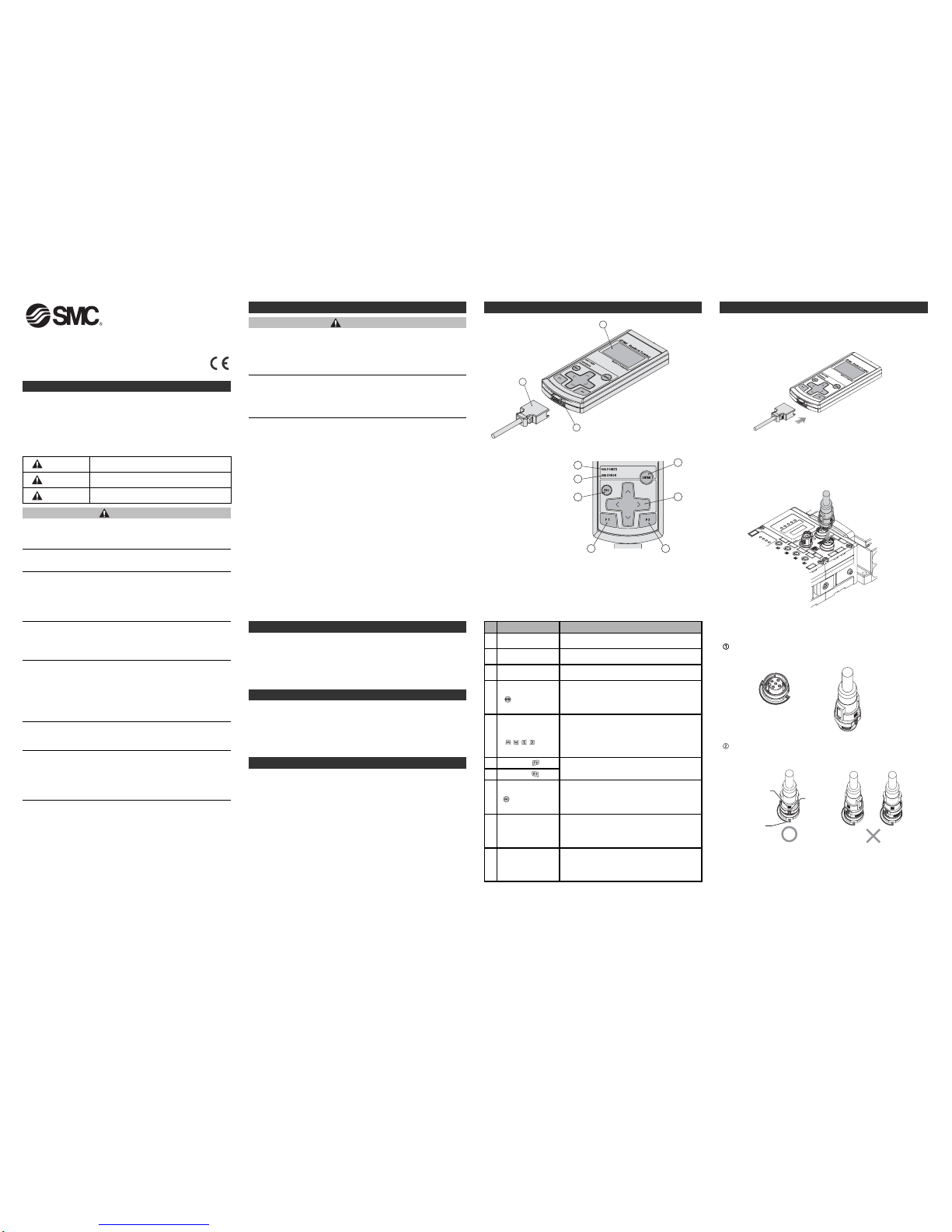
5. Names / Functions of individual Parts
No.
Name
Description
3
Handheld Terminal
cable
Cable to connect the SI Unit to the Handheld
Terminal.
5
Cursor move
button
()
,,,
This button is used to move the cursor in LCD
display upward/downward and right/left
direction. Select the required item using this
button. Use this button to increase/decrease or
turn ON/OFF the setting value.
10 Power LED
The Power LED (Green) turns ON when the
Handheld Terminal is connected with an EX600
SI Unit and power supply for Control/Input is
ON.
4
ENTER button
()
In selecting screen, this button is used for
selecting the required item. In setting screen,
pressing this button registers the selected
contents.
6
F2 button ( )
This button functions according to the indication
or instruction displayed on the screen.
7
F1 button ( )
8
Escape button
()
In selecting screen, this button is used to return
to the previous screen. Pressing this button
cancels the setting contents.
1
LCD display
2 Connector
Connector for Handheld Terminal cable.
Displays the operation items and information
about the unit.
9 Error LED
The Error LED (Red) turns ON when EX600
diagnostics error occurs. (Refer to the
"Troubleshooting" and "Error Code" section for
further details.)
Mark at cable end
Mark on the unit
Projected
portion
6. Wiring
2. How to Order
3. Specifications
4. Outline dimensions(mm)
<SPEEDCON Wiring method>
Set the projected portion of the cable connector metal ring (plug /
socket) to the mark at cable end.
Push the connector straight to insert it into the receptacle of the unit.
If inserted without aligning the mark, the connector will not mate with
the receptacle.
Refer to the catalogue or operation manual for this product.
Refer to the catalogue or operation manual for this product.
Refer to the catalogue or operation manual for this product.
The forced input/output function is used to change the signal
status forcibly.
When operating this function, be sure to check the safety of the
surroundings and the installation.
Otherwise injury or equipment damage could result.
Erroneous parameter setting can result in malfunction.
Be sure to confirm the settings.
Otherwise injury or equipment damage could result.
When setting the parameters to the factory defaults, unpredictable
operation of connected equipment may occur.
It is essential to carry out this operation paying attention to safety.
Otherwise injury or equipment damage could result.
1
3
2
4
5
67
8
9
10
1. Safety Instructions
(continued)
Perform a proper functional check after completing maintenance.
Stop operation if the equipment does not function properly.
Safety cannot be assured due to unexpected malfunction.
Switching the HOLD/ CLEAR function selection mode, will switch
the operation of the input / output signal and emergency stop, so
pay due attention to safety when setting.
There is a risk of injury and equipment damage.
Do not disassemble, modify (including change of printed circuit
board) or repair this product.
Injury or failure can result.
<Wiring Method
(connecting Handheld Terminal connector)
>
When inserting the connector into the Handheld Terminal, insert
the connector straight in until it clicks into place.
<Wiring Method (connecting to the SI Unit)>
The M12 cable connector is connected to the "connector for
Handheld Terminal" on the SI Unit. The method of connecting
the cable to the SI Unit is explained in the "<SPEEDCON Wiring
method>" section.
If instructions are not followed there is a
possibility of serious injury or loss of life.
If instructions are not followed there is a
possibility of injury or equipment damage.
In extreme conditions, there is a possible result
of serious injury or loss of life.
DANGER
WARNING
CAUTION
These safety instructions are intended to prevent hazardous situations
and/or equipment damage.
These instructions indicate the level of potential hazard by label of
"DANGER", "WARNING"or "CAUTION", followed by important safety
information which must be carefully followed.
To ensure safety of personnel and equipment the safety instructions in
this manual and the product catalogue must be observed, along with
other relevant safety practices.
EX600-TFM07GB
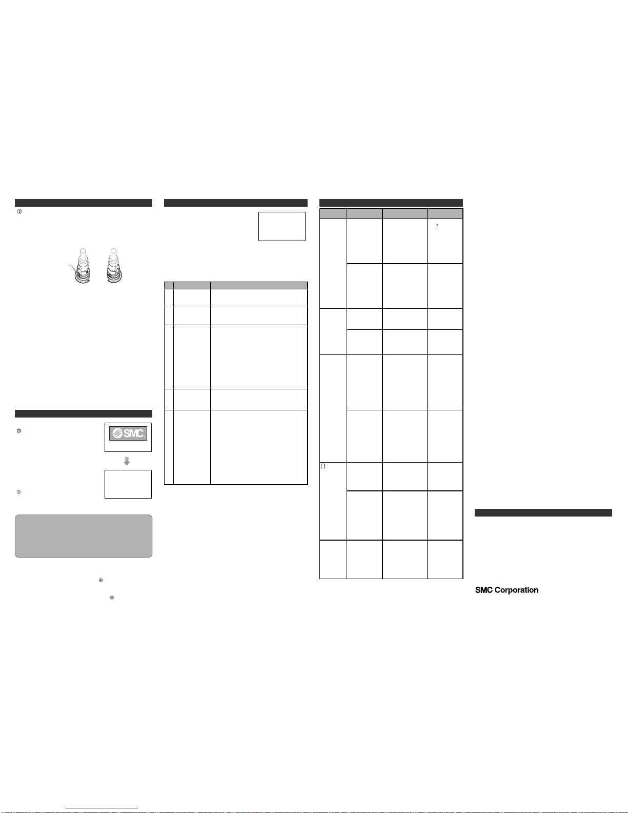
6. Wiring
(continued)
Turn-lock mechanism
of the connector
Turn the connector clockwise. It stops when turned 1/4 turn.Turn it
further. When the connector is turned 1/2 turn from the original position, the projected portion is set at the diagonal position to the mark
and the turn is completed. Check that the connector is securely
locked.
If the connector is turned excessively, it will become difficult to
remove.
<Basic Operation>
Turning ON the power
(1) When the SI Unit and the Handheld
Terminal are connected with the cable,
the power is supplied to the Handheld
Terminal.
(2) The POWER LED (green) turns ON
and the start up screen is displayed on
the LCD display.
(3) After about 2 seconds, the Main Menu
screen is displayed.
Turning off the Power
During Main Menu screen, remove the
cable connected to the SI Unit.
SI Interface
Ver.X.X.
After
2 seconds
Main Menu
1.I/O monitor
2.Diagnosis Data
3.Sys. Configuration
4.Parameter Setting
5.Terminal Setting
Notes
- Be sure to put seal caps on any unused connectors of the EX600 SI
Unit. Appropriate use of seal caps enables the unit to achieve IP67
protection.
- The cable can be removed only when the Handheld Terminal displays the Main Menu screen. Do not remove the cable while at any
other screen, or this may cause equipment malfunction.
<Power Saving>
When the power supply is ON, and the button is pressed for
2 seconds or more the Handheld Terminal will enter power
saving mode.
The LCD display will turn OFF. Pressing the button again will
recover from the power saving mode.
7. Setting
7. Setting
(continued)
<Main Menu>
The Handheld Terminal has five
modes for the various functions.
Each mode is composed of layers
with more detailed contents
enabling setting and checking of
each item.
Mode Selection Screen
Main Menu
1.I/O monitor
2.Diagnosis Data
3.Sys. Configuration
4.Parameter Setting
5.Terminal Setting
No.
1
2
3
4
5
Mode
I/O Monitor mode
Diagnosis Data
mode
System
Configuration
mode
Parameter Setting
mode
Terminal Setting
mode
Description
This mode displays the I/O status of the unit and
carries out forced I/O.
This mode displays the I/O status of the unit, the
detailed error contents and error log.
This mode is used to configure the following
system operations:
(1)Input the tag name of each unit.
(2)Update the memorized information of manifold
configuration.
(3)Change the hold/clear function to SW setting of
the SI unit or setting by the Handheld Terminal.
(4)Clear the ON/OFF counter of each I/O Unit.
(5)Reset the parameter of each unit to the factory
default value.
(6)Clear all error logs.
This mode is used to set each parameter type.
This mode is used to set the following:
(1)Set the contrast of the LCD display screen.
--> 9 levels
(2)Set the brightness of the LCD display screen.
--> 5 levels
(3)Set the click sound level for button operation.
--> 5 levels
(4)Set the time before entering power saving
mode when there is no operation.
--> None, 1 min, 3 min, 7 min, 10 min
(5)Cancel the operation settings of the Handheld
Terminal and return to the initial setting values.
(6)Change the password.
8.Trouble Shooting
Indication
Power LED
is OFF
LCD display
is not active
"Warning
System
access is not
completed" is
displayed on
the LCD
screen
is
displayed on
the LCD
screen.
?
ERROR LED
is ON
Problem
EX600 Power
supply voltage
level for control /
input is not within
specification.
The cable for the
handheld terminal
is defective.
Handheld terminal
is in power save
mode.
LCD is damaged.
The handheld
terminal cable is
defective.
A connection
between the units
is defective.
Manifold
configuration
memory error has
occurred.
Connection
between the units
is defective.
EX600 diagnostic
error has
occurred.
Investigation method
- Check if "PWR" LED
on the SI Unit is
green.
- Confirm that the
regulated power
supply voltage is
supplied to the
endplate.
- Confirm the
Handheld terminal
cable is connected
correctly.
- Confirm the integrity
of the connection of
the Handheld
terminal cable.
Press ESC button.
Confirm that the LCD
is active.
If LCD does not
become active after
initial checks above,
LCD is damaged.
- Confirm that the
Handheld terminal
cable is connected
correctly.
- Confirm there is no
loose connection in
the Handheld
terminal cable.
Confirm if SI Unit
"ST(M)" LED is green.
Confirm if configuration
memory is in active
state and manifold
configuration is
correct.
Confirm the SI Unit
"ST(M)" LED is green.
Confirm error content
through diagnostic
data mode.
Counter-measure
Supply voltage of
24V 10% to the
power supply for
control / input.
Refer to the
manual of the
corresponding
unit.
- Reconnect the
cable correctly.
- Ensure the cable
connections are
secure.
Same as left.
Stop operation
and contact SMC
sales office.
- Reconnect the
cable correctly.
- Ensure the cable
connections are
secure.
If LED is flashing
red and green,
there is a
connection fault
between the units.
Re-make and
then confirm the
connection
between the units.
Please refer to
respective unit's
operation manual
to clear the error.
If the LED is
flashing red and
green, there is a
connection fault
between the units.
Re-make and
then confirm the
connection
between the units.
Refer to error
code list and
respective unit's
operation manual
for counter
measure to the
error.
9. Contact
AUSTRIA (43) 2262 62280 NETHERLANDS (31) 20 531 8888
BELGIUM (32) 3 355 1464 NORWAY (47) 67 12 90 20
CZECH REP. (420) 541 424 611 POLAND (48) 22 211 9600
DENMARK (45) 7025 2900 PORTUGAL (351) 21 471 1880
FINLAND (358) 207 513513 SLOVAKIA (421) 2 444 56725
FRANCE (33) 1 6476 1000 SLOVENIA (386) 73 885 412
GERMANY (49) 6103 4020 SPAIN (34) 945 184 100
GREECE (30) 210 271 7265 SWEDEN (46) 8 603 1200
HUNGARY (36) 23 511 390 SWITZERLAND (41) 52 396 3131
IRELAND (353) 1 403 9000 UNITED KINGDOM (44) 1908 563888
ITALY (39) 02 92711
URL http://www.smcworld.com (Global) http://www.smceu.com (Europe)
Specifications are subject to change without prior notice from the manufacturer.
© SMC Corporation All Rights Reserved.
 Loading...