

Page 1
Fieldbus system
CC-Link Compatible GW unit
Operation Manual
EX510-GMJ1
Note: Specifications are subject to change without prior notice and any obligation on the part of the manufacturer.
© 2003-2017 SMC Corporation All Rights Reserved
EX※※-OMH0014-C
Akihabara UDX 15F, 4-14-1, Sotokanda, Chiyoda-ku, Tokyo 101-0021, JAPAN
Phone: +81 3-5207-8249 Fax: +81 3-5298-5362
URL http://www.smcworld.com
Page 2

1
Table of Contents
Thank you for purchasing an SMC fieldbus system EX510
series.
Please read this manual carefully before operating the product
and make sure you understand its capabilities and limitations.
Please keep this manual handy for future reference.
OPERATOR
•This operation manual has been written for those who have
knowledge of machinery and apparatuses that use fieldbus
system and have full knowledge of assembly, operation and
maintenance of such equipment.
•Please read this operation manual carefully and understand it
before assembling, operating or providing maintenance service
to the actuator.
Safety Instructions 2
Product Summary 6
Name of Parts/ Accessories 7
Dimensions 8
Settings 9
Specifications 11
Wiring 12
Display/ Switch Setting 19
Troubleshooting 23
Page 3
32
Safety Instructions
The product and this manual contain essential information to
protect users and others from possible injury and property
damage and to ensure correct handling.
Please check that you fully understand the definition of the
following messages (signs) before going on to read the text, and
always follow the instructions.
Please read the operation manual of related apparatus and
understand it before operating the actuator.
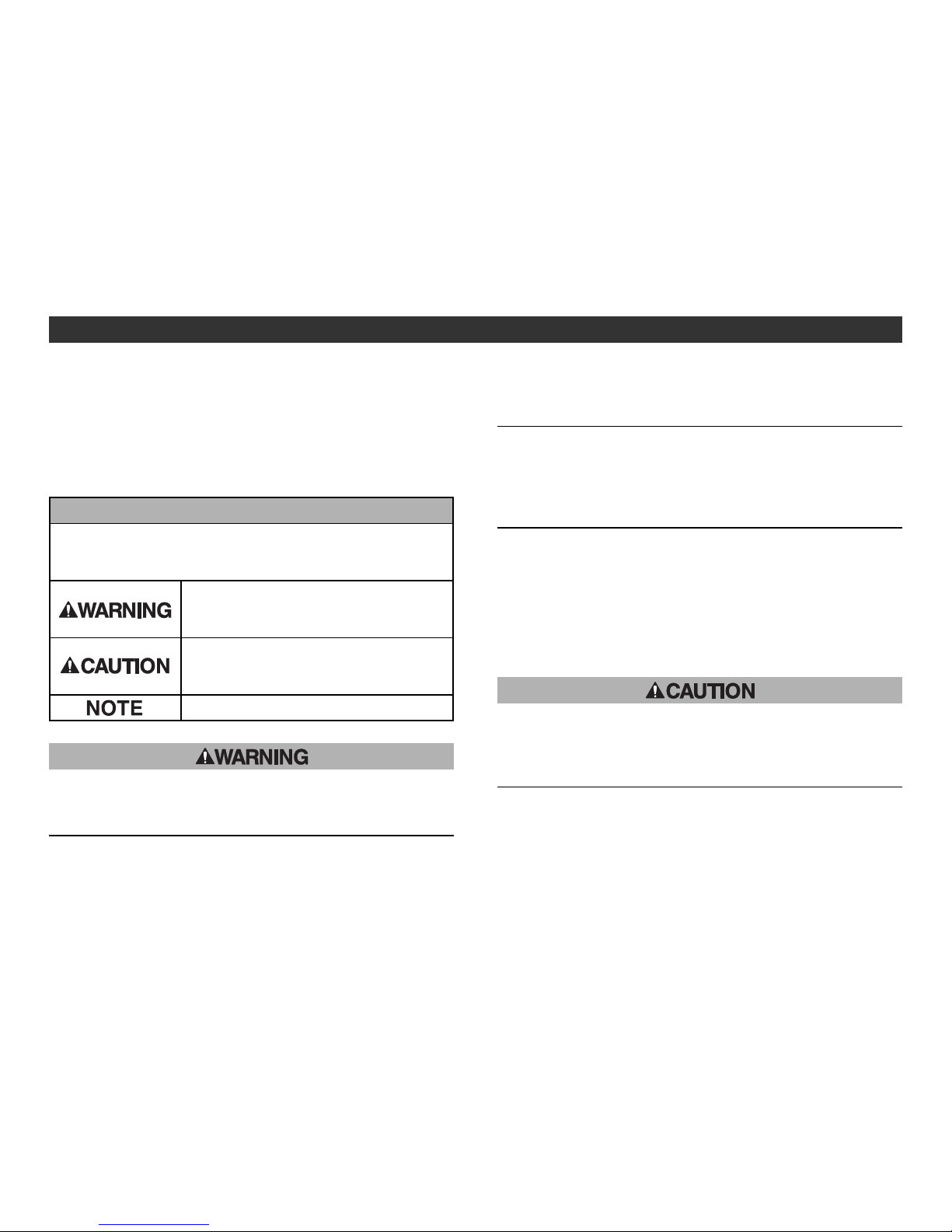
Read this manual and follow its instructions. Signal words such as
WARNING, CAUTION and NOTE, will be followed by important
safety information that must be carefully reviewed.
Indicates a potentially hazardous situation
which could result in death or serious
injury if you do not follow instructions.
Gives you helpful information.
Indicates a potentially hazardous situation
which if not avoided, may result in minor
injury or moderate injury.
Do not operate the product outside of the specifications.
Fire, malfunction, or damage to the product can result.
Verify the specifications before use.
Do not disassemble, modify (including change of printed
circuit board) or repair.
An injury or failure can result.
IMPORTANT MESSAGES
Do not operate in an atmosphere containing flammable or
explosive gases.
Fire or an explosion can result.
This product is not designed to be explosion proof.
If using the product in an interlocking circuit:
•Provide a double interlocking system, for example a
mechanical system.
•Check the product regularly for proper operation.
Otherwise malfunction can result, causing an accident.
The following instructions must be followed during
maintenance:
•Turn off the power supply.
•Stop the air supply, exhaust the residual pressure and
verify that the air is released before performing
maintenance.
Otherwise an injury can result.
After maintenance is complete, perform appropriate
functional inspections.
Stop operation if the equipment does not function properly.
Safety cannot be assured in the case of unexpected malfunction.
Provide grounding to assure the noise resistance of the
product.
Individual grounding should be provided close to the product with
a short cable.
Page 4

54
Safety Instructions (continued)
Note
•When conformity to UL is required, the SI unit should be used
with a UL1310 Class 2 power supply.
Follow the instructions given below when handling your product.
Or, it will have a risk of being damaged and operating failure.
•Operate product with the specified voltage.
•Reserve a space for maintenance.
•Do not remove labels.
•Do not drop, hit or apply excessive shock to the product.
•Follow the specified tightening torque.
•Never mount a product in a location that will be used as a
foothold.
•Do not bend or apply tensile force to cables, or apply force by
placing heavy load on them.
•Connect wires and cables correctly.
•Do not connect wires while the power is on.
•Do not lay wires or cables with power line or high-voltage line in
the same wiring route.
•Verify the insulation of wiring.
•Separate power line for solenoid valves from power line for
Input and control unit.
•Take appropriate measures against noise, such as using a
noise filter, when the product is incorporated into equipment.
•Select the proper type of protection according to the
environment of operation.
•Take sufficient shielding measures when installing at the
following place.
(1) A place where noise due to static electricity is generated
(2) A place where electric field strength is high
(3) A place where there is radioactive irradiation
(4) A place near power line
•Do not use the product near by a place where electric surges
are generated.
•When a surge-generating load such as a relay or solenoid is
driven directly, use an product with a built-in surge absorbing
element.
•The product is CE marked, but not immune to lightning strikes.
Take measures against lightning strikes in the system.
•Prevent foreign matter such as remnant of wires from entering
the product to avoid failure and malfunction.
•Mount the product in a place that is not exposed to vibration or
impact.
•Do not use the product in an environment that is exposed to
temperature cycle.
•Do not expose the product to direct sunlight.
•Keep the specified ambient temperature range.
•Do not expose the product to heat radiation from a heat source
located nearby.
•Set the switches by using a sharp-pointed screwdriver etc.
•Turn off the power supply, stop the supplied air, exhaust the
residual pressure and verify the release of air before performing
maintenance.
•Perform maintenance and check regularly.
•Perform a proper functional check.
•Do not use solvents such as benzene, thinner etc. to clean the
product.
Page 5
76
Product Summary
System structure
( )
( )
Power supply
for output
Power supply
for input and
controling GW
24 VDC
24 VDC
GW unit
Input unit
1 connector
2 inputs type
Input unit
1 connector
1 input type
connecting to
4 sets maximum
Branch cable
(EX510-FC )
Valve manifold
with SI unit
connecting to
4 sets maximum
Connecting to bus
at upper level
(CC-Link)
( )
( )
The system which realizes wiring saving and distributed
installation by connecting to CC-Link. The signal to CC-Link is
transmitted by GW unit, and the signal to input/output device
which is installed discretely is collected by GW unit.
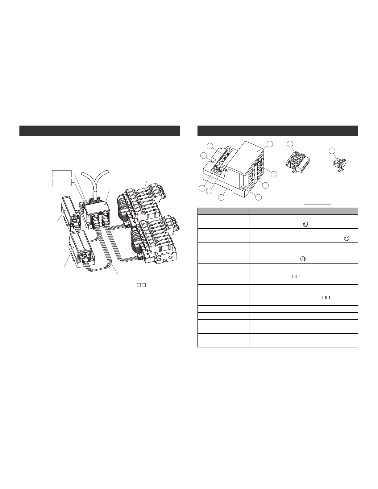
Name of Parts/ Accessories
Communication
connector for
CC-Link
(1 piece)
Power supply
connector
(2 pieces)
Accessory
10
11
8
4
7
5
1
6
9
2
3
No. Parts Purpose
1
Communication
socket (BUS)
Connect to CC-Link line with an accessory
connector for CC-Link ( ). ∗
2
Power supply
socket (PWR(V))
Supplying power for output instruments such as a
solenoid valve with an accessory connector ( ). ∗
3
Power supply
socket (PWR)
Supplying power for controlling GW and for
input instruments such as a sensor with an
accessory connector
()
. ∗
4
GW unit side
branch connector
(for input)
Connecting an input unit etc. by using branch
cables (EX510-FC ).
5
GW unit side
branch connector
(for output)
Connecting SI unit (manifold valve) etc. by
using branch cables (EX510-FC ).
6 FG terminal Used for grounding
7 Mounting hole
Used when a unit is mounted with two M4 screws.
8
DIN rail mounting
slot
Used when a unit is mounted to DIN rail.
9
Display/ switch
setting part
Sets up the switch on such as LED display and
address, I/O points.
∗: For wiring method, refer to "Wring" in the "Operation Manual".
Page 6

98
Dimensions (in mm)
64
25.7
COM A
COM B
COM C
COM D
O
UTPUTINPUT
60 80
16
PWR
(
V)
P
WR
B
US
Settings
Perspective drawing
(tolerance 0.2)
16
PWR
(
V)
PWR
B
US
OUTPUT
INPUT
70 5
54 5
2 × M4
∗: Tightening torque
: 0.8 Nm
DIN rail
PWR
(V)
PWR
BUS
Mounted by screw
Mounted on DIN rail
Page 7

1110
Mounting Removal
Claw 1
Claw 2
DIN rail fixing plate
1
2
3
4
Put Claw 1 of the body under DIN rail and push it upward.
Push down Claw 2 to the opposite rail until the claw clicks
securely on to rail.
(Mounting procedure and )
For removing, lever up the DIN rail fixing plate of the body with a
flat blade screwdriver, and remove it by tilting Claw 2 side forward.
(Removal procedure and )
Settings (continued)
Specifications
Basic specifications
Compatible system
Number of station occupied
CC-Link Ver.1.10
3 stations (it is possible to change for 2 stations)
Station type Remote device station
Rated voltage
Power supply
voltage
24 VDC
Power supply for input and controlling GW: 24 VDC ±10%
Power supply for output: 24 VDC+10%/-5%
(Warning for voltage drop is given at approx. 20 V)
Rated current
Input/ output
point
Power supply for input and controlling GW: Max. 4.1 A
(Inside GW unit: 0.1 A, input unit: 4 A)
Current for output: Max. 6 A
Input point: Max. 64/ Output point: Max. 64
(Changeable by switch settings)
Operation
temp. range
-10 to 50 oC
Higher-level bus
Communication speed
156 kbps
20 cm and more
625 kbps 2.5 Mbps
Cable length between stations
1200 m
900 m 400 m
5 Mbps 10 Mbps
160 m 100 m
Maximum extended cable length
Lower level bus
Number of branches for
input/ output
4 branches for input
4 branches for output
Communication type
Communication protocol: Dedicated for SMC
Communication speed : 750 kbps
Current for input branch
Max. 1 A per branch
Current for output
branch
Max. 1.5 A per branch
Branch cable length
At 0.75 A per branch: 20 m or less
At 1.0 A per branch : 16 m or less
At 1.5 A per branch : 10 m or less
∗1: Input terminals are not isolated from Power source.
∗2: Do not connect outside Power source to Input and Output terminals.
Page 8

1312
Internal circuit
DC-DC
converter
(Insulation)
+24 V
0 V
COM D
INPUTOUTPUT
+24 V
RD+
RD0 V
+24 V
0 V
Power supply
for output
Power supply
for input and
controlling GW
+24 V
TD+
TD0 V
COM A
INPUTOUTPUT
+24 V
RD+
RD0 V
+24 V
TD+
TD0 V
(Brown)
DA
DB
DG
SLD
FG
FG
Wiring
Internal circuit
Insulating cap
Brown
Black
White
Blue
Cover Body Branch cable
Pin no. display
Branch wiring
The wiring between each unit should use branch cables, and be
connected with branch connectors.
SI unit and Input unit have 2 branch connectors for each.
Pressure welding for branch connector
The method of pressure welding for branch connector is
explained.
(1)Components
(2)Working procedure
Set a branch cable to the cover.
1) Set the brown wire of the branch
cable so that it comes to the pin #1.
2) Meet the cable end to the insulating
cap at the cover.
3) Fold the cover so that the branch
cable can be put between the cover.
4) Fix the latch tip by inserting to
a hole for fixing latch.
Note) Check the color of wire written on a
branch connector and the color of
branch cable are same.
Fix to a body tentatively.
Fit 4 latches on a body to 4 ditches on
the cover, and press them until the
latch engages to the level 1.
Pin #1: Brown wire
Hold for
fixing latch
Latch
Page 9

1514
Wiring (continued)
Wiring of branch cables
4 branches for input
4 branches for output
To SI unit
To Input unit
COM D
COM C
COM B
COM A
Branch connector
at cable side
Branch cable
Branch connector
at GW unit side
Insert branch connector on the table side from the bottom
(COM A, B, C, D of branch connector of GW unit side).
Press fitting
Press the cover to the body with plier etc.
Confirmation
It is completed with a check on 4 latches
engaging.
NOTE
1. Select a branch cable length suitable to avoid stress
being applied to the branch connector and cable,
and provide sufficient cable length for maintenance.
2. Do not pull the branch connector and branch cable
after wiring. There is a risk of damage.
3. Do not open and close the branch connector hook
repeatedly. There is a risk of damage.
4. Cut the branch cable and replace the branch
connector when the branch connector hook is broken
or no longer functions.
5. Use SMC branch connector
(product No.: EX510-LC1) and branch cable
(product No.: EX510-FC ). Usage of other branch
connector or cable is out of the applicable range of
product guarantee.
DA DB DG
SLD
FG
White Yellow
Yellow
Shield
White Shield
Blue
Blue
Drawing 1
E
X
5
1
0
4
3
2
1
Communication wiring
Connect CC-Link dedicated cables to the communication
connector for CC-Link.
(1) Make sure to connect the signal cables to designated pins
(Refer to Drawing 1).
And tighten the connector surely to 0.5 to 0.6 Nm tightening
torque.
Page 10

1716
Communication connector
for CC-Link
Drawing 4
Wiring (continued)
(4) Refer to Drawing 4 about how to connect to the unit.(2) Make sure to connect a "terminating resistor" to the units at
the both ends of the system (Refer to Drawing 2).
DA
Terminal
resister
Master unit
CC-Link
dedicated
cable
CC-Link
dedicated
cable
(Blue)
(White)
(Yellow)
DB
DG
SLD
FG
Terminal
resister
DA
Remote unit
DB
DG
SLD
FG
DA
Local unit
DB
DG
SLD
FG
Drawing 2
Connect the terminal resistor between "DA-DB"
(Refer to Drawing 3).
DA DB DG
SLD
FG
Yellow
White ShieldBlue
Terminating resistor
Drawing 3
(3) The terminal resistor to connecct differs depending on a
cable to use at CC-Link system. Refer to table below.
Cable type Terminal resistor
110 Ω 1/2 W
(brown, brown, brown)
CC-Link dedicated cable
CC-Link dedicated cable compatible to Ver.1.10
130 Ω 1/2 W
(brown, orange, brown)
CC-Link dedicated high performance cable
NOTE
1. CC-Link dedicated high performance cable cannot
be mixed with other cables (CC-Link dedicated
cable, CC-Link dedicated cable compatible with
Ver.1.10).
If mixed, normal transmission of data cannot be
assured.
2. Connect the shield line of CC-Link dedicated cable to
"SLD" of each unit.
Page 11

1918
Wiring (continued)
A. For dual power
supply use
B. For single power
supply use
24 VDC
24 VDC
24 VDC
Display/ Switch Setting
SW1
OFF
ON
OFF
ON
COM C COM DCOM A COM B
SW2
L RUN L ERRPWR(V) PWR
INPUT
Setting for Display
Display
Meaning
PWR
(V)
The power for output is supplied at specified voltage: Lights up
The power for output is not supplied at specified voltage: Goes off
PWR
The power for input and GW unit controlling part is supplied: Lights up
The power for input and GW unit controlling part is not supplied: Goes off
L RUN
Normally communication: Lights up
Communication interrupted: Goes off
L ERR
Communication error: Lights up
Setting of station number and of transmitting speed setting
switch is changed during powered: Lights up
(Blink with 0.4 s interval)
Normally communicating: Goes off
COM A
COM A is receiving data: Lights up ∗
COM A is having no data to receive: Goes off
COM B
COM B is receiving data: Lights up ∗
COM B is having no data to receive: Goes off
COM C
COM C is receiving data: Lights up ∗
COM C is having no data to receive: Goes off
COM D
COM D is receiving data: Lights up ∗
COM D is having no data to receive: Goes off
∗: It is lit when input unit is connected and communicating normally.
Power supply wiring
Connect power supply wiring to the two power supply 2-pin
connectors. Power supply structure consists of 2 systems, but it
can be used with both single power supply and separate power
supply.
Individual power supply for other units is not necessary.
Make sure of connection with the designated pin. Tighten the
connector securely to 0.5 to 0.6 Nm tightening torque.
Power supply connector
Power supply
for output
Power supply
for input and
controlling GW
Power supply connector
PWR
(V)
PWR
0V
24V
24V
0V
Note: A secure earth connection (Protection class 3) should be
performed for FG terminal.
(SLD, FG and FG terminal in communication connector for
CC-Link are connected inside of GW unit.)
Page 12

2120
Station number setting (Switch No.1 to 7)
Set tens digit of station number 10, 20 and 40, and set ones digit
of station number 1, 2, 4 and 8.
All setting are turned OFF at shipment and no station number is set.
Make sure to set the station number in the range of 1 to 62
(with 3 stations occupied).
10987654321
2148102040
ON
SW1
OFF
ON
Tens digit Ones digit Transmission speed
Switch setting
Make sure that switch setting is performed with power supply turned off.
Open the cover, and set DIP switch with a small flat blade
screwdriver, etc.
Display/ Switch Setting (continued)
Setting of address and communication speed (SW1)
Setting of address and communication speed are performed with
SW1.
Swtting of transmission speed (Switch No.8 to 10)
Make sure to set the transmission speed in the range as follows.
All setting are turned OFF at shipment, set to 156 kbps.
Transmission speed
156 kbps
625 kbps
2.5 Mbps
5 Mbps
No.8
OFF
OFF
OFF
OFF
No.9
OFF
OFF
ON
ON
No.10
OFF
ON
OFF
ON
10 Mbps
ON OFF OFF
40
(No.1)
1
Station
number
2
3
4
:
10
11
:
62
63
∗
∗: Station number 63 can be set for 2 stations occupied type.
20
(No.2)
10
(No.3)
8
(No.4)
Tens digit (Switch No.) Ones digit (Switch No.)
4
(No.5)
2
(No.6)
OFF
OFF
OFF OFF OFF
OFF
OFF OFF
OFF
OFF OFF ON
OFF OFF
OFF
OFF OFF ON
OFF
OFF
OFF
OFF ON
OFF
:
:
: : :
:
OFF
OFF
ON OFF OFF
OFF
OFF
OFF
ON OFF OFF
OFF
: :
:
: : :
ON
ON
OFF OFF OFF
ON
ON
ON
OFF
OFF OFF
ON
1
(No.7)
ON
OFF
ON
OFF
:
OFF
ON
:
OFF
ON
Setting of HOLD/CLR, number of stations occupied
and mode (SW2)
Setting of HOLD/CLR, number of stations occupied and mode
are performed with SW2.
654321
ON
SW2
OFF
ON
Unused
∗
Mode setting
Setting of the number
of stations occupied
HOLD/CLR setting
∗: Switch No.5 and No.6 are unused. (Turn them OFF.)
HOLD/CLR No.1
Function
CLR
OFF
HOLD
ON
Output is cleared when an error occurs.
Output is held when an error occurs.
HOLD/CLR setting (Switch No.1)
The setting is as follows.
The setting at shipment is turned OFF, set to CLR.
Page 13

2322
Display/ Switch Setting (continued)
Troubleshooting
Overall system
1
2
3
Remedy/ Disposal
•Check the power for output (24 VDC) is supplied.
•Check the branch cable is connected to SI unit.
•Check the LED for power supply (PWR) and the
LED for communication (COM) at SI unit are ON.
•Ensure output branch current does not exceed the
specification range.
•Program it after checking the wiring specification
of manifold block assembly.
•Check the power for input and controlling GW
(24 VDC) is supplied.
•Check the input unit indication LED is ON.
•Ensure input branch current does not exceed the
specification range.
•Check the connection of UNLIT COM port branch
to input unit.
4
COM A-D is
not LIT
Signals
cannot be
received
even with a
sensor
Solenoid
valve is not
working
Valve is not
working as
program
directs
No. Item
Station setting
No.2
The max. available number
of I/O point
2 station-occupied
OFF
3 station-occupied
ON
No.3
ON
OFF
Input 32/ Output 32
Input 64/ Output 64
Setting of the number of stations occupied
(Switch No.2 to 3)
The setting of the number of stations occupied is performed with
switch No.2 to 3.
3 stations are occupied at shipment.
Mode
No.4
Number of branch
A OFF
B
ON
16 points per port
8 points per port
Valid port
COM A and B
COM A to D
Mode setting (Switch No.4)
Mode setting of each port is available only when 2 stations are
occupied.
No.4 is used for mode setting.
The default setting is mode A.
Page 14

2524
CC-Link compatible communication
No.
1
2
3
Item
PWR LED is
goes off
PWR(V) LED is
goes off
RUN LED is
goes off/
ERR LED is
lights up
Remedy/ Disposal
•Check the power supply for input and controlling
GW (24 VDC) is supplied.
•Check the power for output (24 VDC) is supplied.
•Check the power supply voltage for output is
getting as low as under 20 V.
•Check the signal line from PLC is correctly
connected.
•Check the wiring and pin numbers.
•Check the address setting is correct.
Troubleshooting (continued)
4
ERR LED is
flushing
•Check the communication speed setting/ station
number setting is changed halfway.
∗: Refer to "Operation Manual" for detail of troubleshooting.
<MEMO>
 Loading...