

SMC Networks EX510-GMJ1 Series Operation Manual
No.EX##-OMI0001-E
PRODUCT NAME
Fieldbus system
(CC-Link compliant)
MODEL / Series / Product Number
EX510-GMJ1 Series

-1-
No.EX##-OMI0001-E
Table of Contents
Safety Instructions 3
Model Indication and How to Order 8
Summary of Product Parts 9
Definition and terminology 10
Common Specifications 12
EX510 GW Unit
Summary of Product Parts 13
Mounting and Installation 14
Installation 14
Wiring 15
Setting 19
Specifications 25
Specifications 25
Dimensions 26
SI Unit
Summary of Product Parts 27
Mounting and Installation 29
Installation 29
Wiring 30
Setting 34
Specifications 34
Specifications 34
Dimensions 35
Output Unit
Summary of Product Parts 36
Mounting and Installation 37
Installation 37
Wiring 38
Specifications 41
Specifications 41
Dimensions 41

-2-
No.EX##-OMI0001-E
Input Unit
Summary of Product Parts 42
Mounting and Installation 43
Installation 43
Wiring 45
Specifications 48
Specifications 48
Dimensions 48
Maintenance 49
Troubleshooting 50
Option 55
-3-
No.EX##-OMI0001-E
Safety Instructions
These safety instructions are intended to prevent hazardous situations and/or equipment damage.
These instructions indicate the level of potential hazard with the labels of "Caution", "Warning" or
"Danger". They are all important notes for safety and must be followed in addition to International
standards (ISO/IEC)
∗1)
and other safety regulations.
∗1) ISO 4414: Pneumatic fluid power -- General rules relating to systems.
ISO 4413: Hydraulic fluid power -- General rules relating to systems.
IEC 60204-1: Safety of machinery -- Electrical equipment of machines. (Part 1: General requirements)
ISO 10218-1992: Manipulating industrial robots -Safety.
etc.
Caution :
CAUTION indicates a hazard with a low level of risk which, if not avoided,
could result in minor or moderate injury.
Warning :
WARNING indicates a hazard with a medium level of risk which, if not
avoided, could result in death or serious injury.
Danger :
DANGER indicates a hazard with a high level of risk which, if not avoided,
will result in death or serious injury.
Warning
1. The compatibility of the product is the responsibility of the person who designs the
equipment or decides its specifications.
Since the product specified here is used under various operating conditions, its compatibility with specific
equipment must be decided by the person who designs the equipment or decides its specifications based on
necessary analysis and test results. The expected performance and safety assurance of the equipment will be
the responsibility of the person who has determined its compatibility with the product. This person should also
continuously review all specifications of the product referring to its latest catalogue information, with a view to
giving due consideration to any possibility of equipment failure when configuring the equipment.
2. Only personnel with appropriate training should operate machinery and equipment.
The product specified here may become unsafe if handled incorrectly. The assembly, operation and
maintenance of machines or equipment including our products must be performed by an operator who is
appropriately trained and experienced.
3. Do not service or attempt to remove product and machinery/equipment until safety is confirmed.
1. The inspection and maintenance of machinery/equipment should only be performed after measures to prevent
falling or runaway of the driven objects have been confirmed.
2. When the product is to be removed, confirm that the safety measures as mentioned above are implemented
and the power from any appropriate source is cut, and read and understand the specific product precautions of
all relevant products carefully.
3. Before machinery/equipment is restarted, take measures to prevent unexpected operation and malfunction.
4. Contact SMC beforehand and take special consideration of safety measures if the product is
to be used in any of the following conditions.
1. Conditions and environments outside of the given specifications, or use outdoors or in a place exposed to direct
sunlight.
2. Installation on equipment in conjunction with atomic energy, railways, air navigation, space, shipping, vehicles,
military, medical treatment, combustion and recreation, or equipment in contact with food and beverages,
emergency stop circuits, clutch and brake circuits in press applications, safety equipment or other applications
unsuitable for the standard specifications described in the product catalogue.
3. An application which could have negative effects on people, property, or animals requiring special safety
analysis.
4. Use in an interlock circuit, which requires the provision of double interlock for possible failure by using a
mechanical protective function, and periodical checks to confirm proper operation.
-4-
No.EX##-OMI0001-E
Caution
The product is provided for use in manufacturing industries.
The product herein described is basically provided for peaceful use in manufacturing industries.
If considering using the product in other industries, consult SMC beforehand and exchange specifications or
a contract if necessary.
If anything is unclear, contact your nearest sales branch.
Limited warranty and Disclaimer/Compliance Requirements
The product used is subject to the following "Limited warranty and Disclaimer" and "Compliance
Requirements".
Read and accept them before using the product.
Limited warranty and Disclaimer
1. The warranty period of the product is 1 year in service or 1.5 years after the product is delivered.
∗2)
Also, the product may have specified durability, running distance or replacement parts. Please
consult your nearest sales branch.
2. For any failure or damage reported within the warranty period which is clearly our responsibility, a
replacement product or necessary parts will be provided.
This limited warranty applies only to our product independently, and not to any other damage
incurred due to the failure of the product.
3. Prior to using SMC products, please read and understand the warranty terms and disclaimers noted
in the specified catalogue for the particular products.
∗2) Vacuum pads are excluded from this 1 year warranty.
A vacuum pad is a consumable part, so it is warranted for a year after it is delivered.
Also, even within the warranty period, the wear of a product due to the use of the vacuum pad or failure due to
the deterioration of rubber material are not covered by the limited warranty.
Compliance Requirements
1. The use of SMC products with production equipment for the manufacture of weapons of mass
destruction (WMD) or any other weapon is strictly prohibited.
2. The exports of SMC products or technology from one country to another are governed by the
relevant security laws and regulation of the countries involved in the transaction. Prior to the
shipment of a SMC product to another country, assure that all local rules governing that export are
known and followed.
-5-
No.EX##-OMI0001-E
Operator
♦This operation manual is intended for those who have knowledge of machinery using pneumatic
equipment, and have sufficient knowledge of assembly, operation and maintenance of such
equipment. Only those persons are allowed to perform assembly, operation and maintenance.
♦Read and understand this operation manual carefully before assembling, operating or providing
maintenance to the product.
■Safety Instructions
Warning
■Do not disassemble, modify (including changing the printed circuit board) or repair.
An injury or failure can result.
■Do not operate the product outside of the specifications.
Do not use for flammable or harmful fluids.
Fire, malfunction, or damage to the product can result.
Verify the specifications before use.
■Do not operate in an atmosphere containing flammable or explosive gases.
Fire or an explosion can result.
This product is not designed to be explosion proof.
■If using the product in an interlocking circuit:
•Provide a double interlocking system, for example a mechanical system.
•Check the product regularly for proper operation.
Otherwise malfunction can result, causing an accident.
■The following instructions must be followed during maintenance:
•Turn off the power supply.
•Stop the air supply, exhaust the residual pressure and verify that the air is released before performing
maintenance.
Otherwise an injury can result.
Caution
■After maintenance is complete, perform appropriate functional inspections.
Stop operation if the equipment does not function properly.
Safety cannot be assured in the case of unexpected malfunction.
■Provide grounding to assure the safety and noise resistance of the GW unit.
Individual grounding should be provided close to the product with a short cable.

-6-
No.EX##-OMI0001-E
■NOTE
○Follow the instructions given below when designing, selecting and handling the product.
•The instructions on design and selection
(installation, wiring, environment, adjustment, operation,
maintenance, etc.)
described below must also be followed.
∗Product specifications
•When conformity to UL is necessary the SI unit must be used with a UL1310 Class2 power supply.
•Use the specified voltage.
Otherwise failure or malfunction can result.
•Reserve a space for maintenance.
Allow sufficient space for maintenance when designing the system.
•Do not remove any nameplates or labels.
This can lead to incorrect maintenance, or misreading of the operation manual, which could cause damage or
malfunction to the product.
•It may also result in non-conformity to safety standards.
•Product handling
∗Installation
•Do not drop, hit or apply excessive shock to the fieldbus system.
Otherwise damage to the product can result, causing malfunction.
•Tighten to the specified tightening torque.
If the tightening torque is exceeded the mounting screws may be broken.
•Never mount a product in a location that will be used as a foothold.
The product may be damaged if excessive force is applied by stepping or climbing onto it.
∗Wiring
•Avoid repeatedly bending or stretching the cables, or placing heavy load on them.
Repetitive bending stress or tensile stress can cause breakage of the cable.
•Wire correctly.
Incorrect wiring can break the product.
•Do not perform wiring while the power is on.
Otherwise damage to the fieldbus system and/or I/O device can result, causing malfunction.
•Do not route wires and cables together with power or high voltage cables.
Otherwise the fieldbus system and/or I/O device can malfunction due to interference of noise and surge voltage
from power and high voltage cables to the signal line.
Route the wires (piping) of the fieldbus system and/or I/O device separately from power or high voltage cables.
•
Confirm proper insulation of wiring.
Poor insulation (interference from another circuit, poor insulation between terminals, etc.) can lead to excess
voltage or current being applied to the product, causing damage.
•Take appropriate measures against noise, such as using a noise filter, when the fieldbus system is
incorporated into equipment.
Otherwise noise can cause malfunction.
•Separate the power line for output devices from the power line for input devices and controlling GW.
Otherwise noise or induced surge voltage can cause malfunction.

-7-
No.EX##-OMI0001-E
∗Environment
•Do not use the product in area that is exposed to corrosive gases, chemicals, sea water, water or
steam.
Otherwise failure or malfunction can result.
•Do not use in an area where surges are generated.
If there is equipment which generates a large amount of surge (solenoid type lifter, high frequency induction
furnace, motor, etc.) close to the fieldbus system, this may cause deterioration or breakage of the internal circuit of
the fieldbus system. Avoid sources of surge generation and crossed lines.
•When a surge-generating load such as a relay or solenoid is driven directly, use an fieldbus system with
a built-in surge absorbing element.
Direct drive of a load generating surge voltage can damage the fieldbus system.
•The product is CE marked, but not immune to lightning strikes. Take measures against lightning strikes
in the system.
•Prevent foreign matter such as remnant of wires from entering the fieldbus system to avoid failure and
malfunction.
•Mount the product in a place that is not exposed to vibration or impact.
Otherwise failure or malfunction can result.
•Do not use the product in an environment that is exposed to temperature cycle.
Heat cycles other than ordinary changes in temperature can adversely affect the inside of the product.
•Do not expose the product to direct sunlight.
If using in a location directly exposed to sunlight, shade the product from the sunlight.
Otherwise failure or malfunction can result.
•Keep within the specified ambient temperature range.
Otherwise malfunction can result.
•Do not operate close to a heat source, or in a location exposed to radiant heat.
Otherwise malfunction can result.
∗Adjustment and Operation
•Set the switches by using a sharp-pointed screwdriver etc.
It may damage set switches.
•Perform settings suitable for the operating conditions.
Incorrect setting can cause operation failure.
For details of each setting, refer to page 20 to 24 of this manual
•Please refer to the PLC manufacturer's manual etc. for details of programming and addresses.
For the PLC protocol and programming refer to the relevant manufacturer's documentation.
∗Maintenance
•Turn off the power supply, stop the supplied air, exhaust the residual pressure and verify the release of
air before performing maintenance.
There is a risk of unexpected malfunction.
•Perform regular maintenance and inspections.
There is a risk of unexpected malfunction.
•After maintenance is complete, perform appropriate functional inspections.
Stop operation if the equipment does not function properly.
Otherwise safety is not assured due to an unexpected malfunction or incorrect operation.
•Do not use solvents such as benzene, thinner etc. to clean the each unit.
They could damage the surface of the body and erase the markings on the body.
Use a soft cloth to remove stains.
For heavy stains, use a cloth soaked with diluted neutral detergent and fully squeezed, then wipe up the stains
again with a dry cloth.
-8-
No.EX##-OMI0001-E
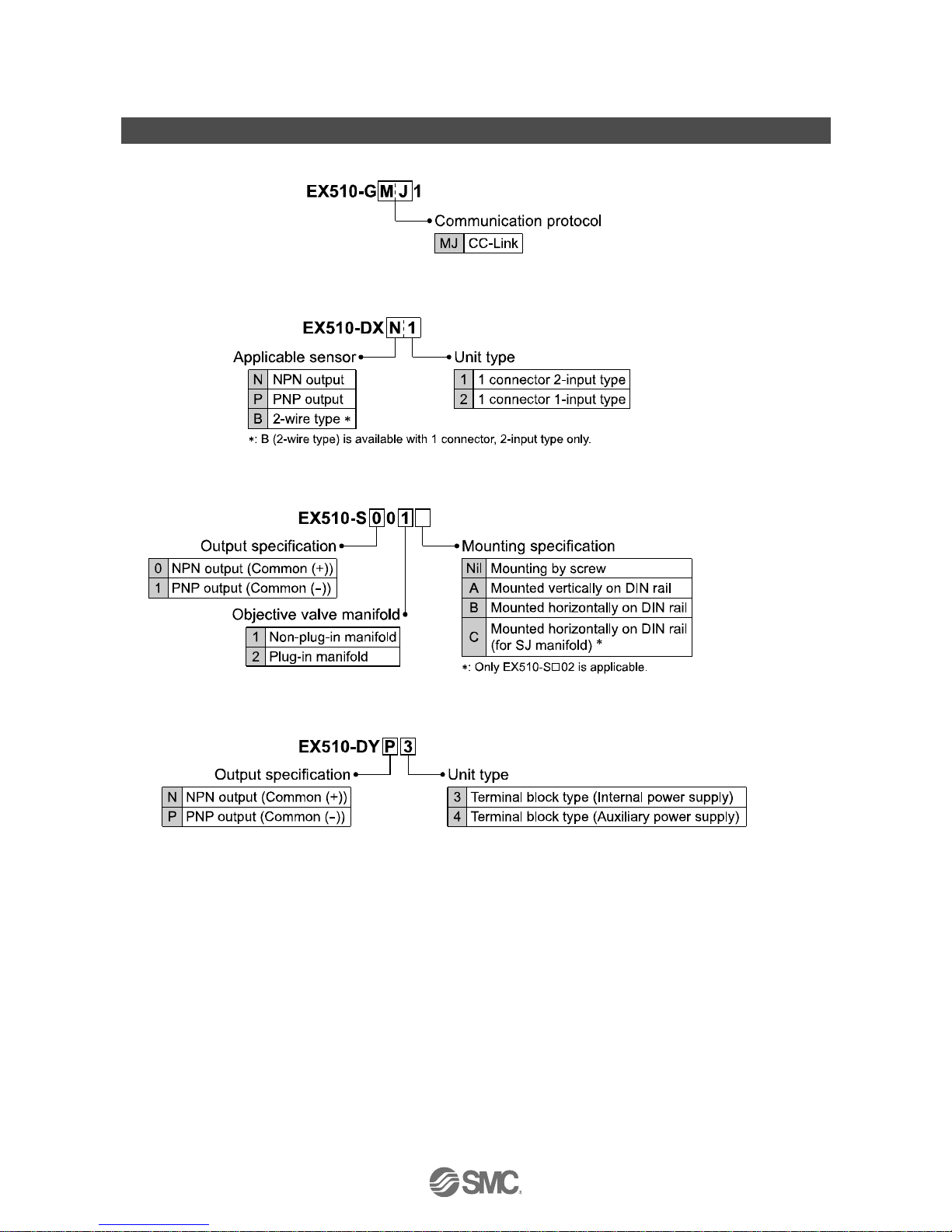
Model Indication and How to Order
•GW unit: CC-Link compatible
•Input unit
•SI unit
•Output unit
For the detail of part no. of solenoid valve manifold and independent solenoid valve with SI unit, refer to
Operation Manual or other equivalent documents of used solenoid valve.
-9-
No.EX##-OMI0001-E
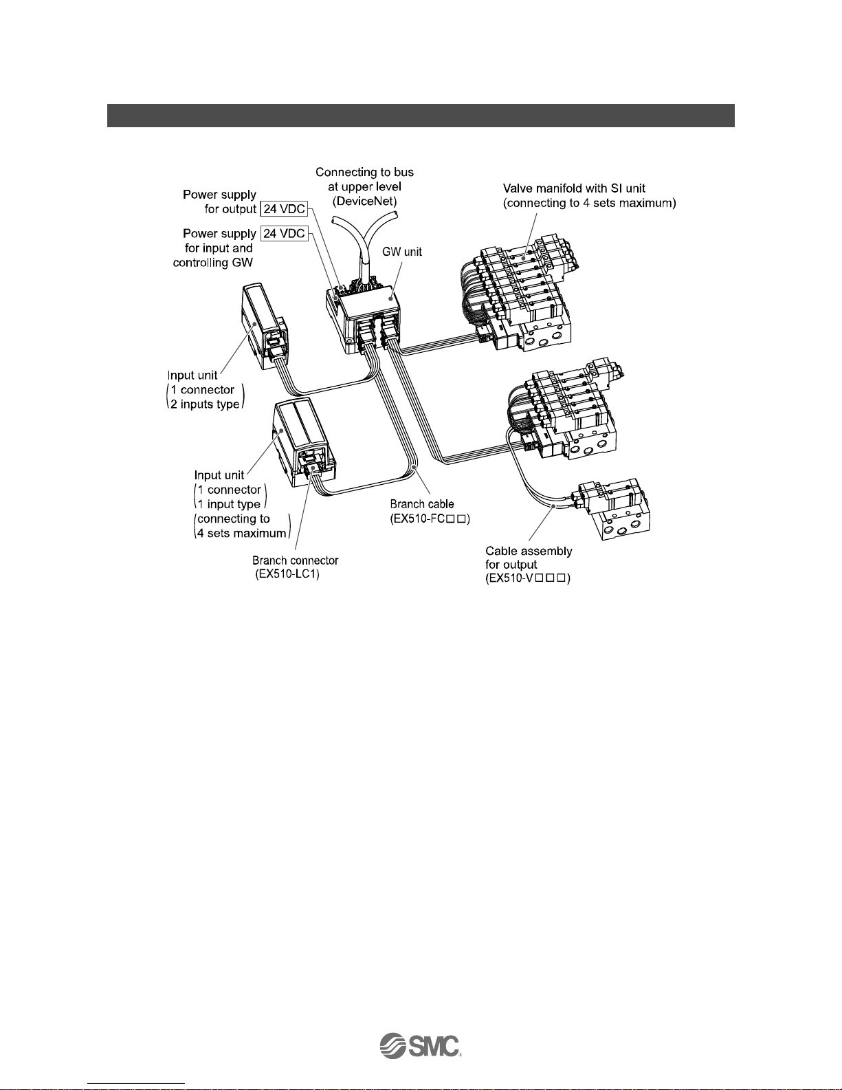
Summary of Product Parts
•System structure
•Capable of decentralized control of 64 input points/64 output points.
Decentralized control of 4 input branches (maximum points of 16 x 4 branches) and 4 output branches
(maximum points of 16 x 4 branches) per one GW unit is possible.
•Easy setting and wiring
Slave side does not need switch settings, but GW unit needs them such as address setting.
It is possible to adjust length of branch cable and crimp branch cable without dedicated tool.
Each slave does not need individual power supply because the branch cable is 4-core flat cable
including a power supply line.
•Compact design
Small and compact design is applied for all of GW unit which realizes decentralized control, Input unit which
connects input equipments such as sensor, and SI unit which connects output equipment such as solenoid
valve.
•Flexible setting of number of occupied station
Utilize I/O point effectively by setting number of occupied station of GW unit.
•Applicable to each type of solenoid valves
SMC’s solenoid valves can be easily wired for serial communication.
(See Manifold Valve for applicable valve.)
The extra output of SI unit can be used to actuate 2-port valve etc, with a cable assembly for output.
-10-
No.EX##-OMI0001-E
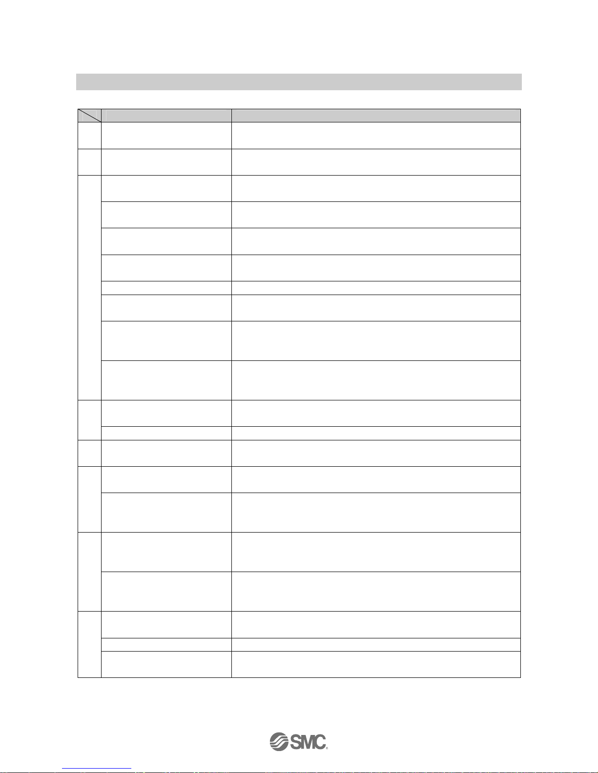
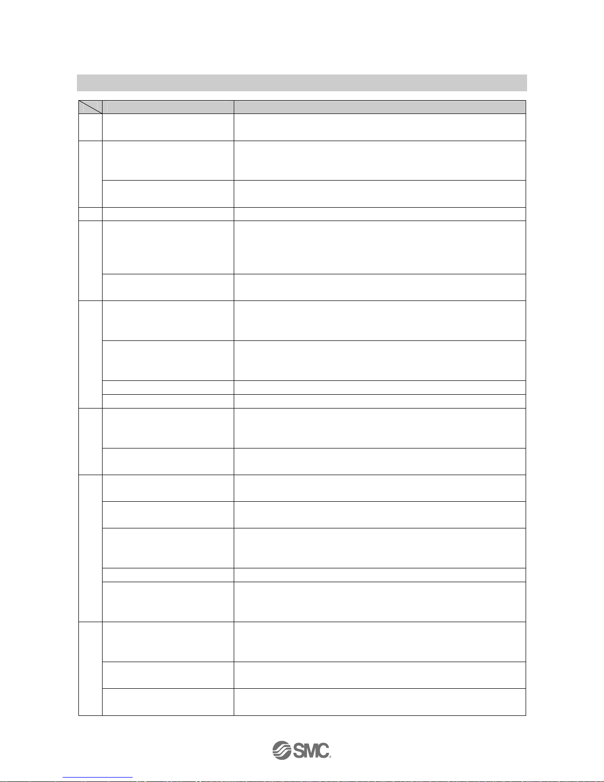
■Definition and terminology
Terms Meaning
A
Address
(Station address)
A number allocated to identify the unit connected on the CC-Link network. It
is not allowed to be duplicated.
B
Branch wiring
A method to branch and connect a communication line and power line from
GW unit to SI unit and Input unit.
Communication connector
A connecting part to transmit a communication signal which goes and returns
between equipments in field bus.
Communication port
A connection port to distribute a communication line and power line from GW
unit to SI unit and Input unit.
Communication speed
A speed at which data is sent and received in field bus etc. It depends on an
equipment (PLC etc.) at high side and is indicated by bps (bit per second).
Connector lock pin
A pin that prevents the connector for connecting load to be connected to SI
unit from coming off.
Conductor resistance A electric resistance of a conductor. It is a value to show ease of current flow.
Current consumption
A current necessary to operate a product normally. In this case, the current
applied to a load is not included.
Current sink type
(NPN output)
An output configuration of an input equipment which uses NPN transistor for
signal outputting part. It sinks current with input and that is the reason why it
is called sink.
C
Current source type
(PNP output)
An output configuration of an input equipment which uses PNP transistor for
signal outputting part. It sources current with input and that is the reason why
it is called source.
Data rate
An amount of data which can be sent from one equipment to the other
equipment. Referred to as transmission speed of data.
D
DIN rail A metallic rail conforming with DIN (German Federation) standard.
E
Enclosure (IP)
An abbreviation of Ingress Protection. It is a standard related to protection of
a product from foreign matters (hand, steel ball, steel wire, dust, water etc.).
FG
An abbreviation of frame ground meaning a body ground. Used to show a
ground simply.
F
Field bus
A standard which uses digital communication to transmit a signal between an
equipment running at factory and field (instrumentation and operation
equipment) and controller.
GND
An abbreviation of ground meaning reference voltage for signal. It has a
same potential level as a shield wire (sheath) of signal line and connector
and is referred to as a reference potential to transmit an electrical signal.
G
GW unit
A unit used to connect protocols conforming with different standards in one
network. In this system, it is regarded as a unit to adjust between CC-Link
protocol and SMC dedicated protocol and connect them.
Impedance
A resistance generated when alternating current is applied to a circuit.
Referred to as alternating current resistance.
Input delay time Refer to "Transmission delay".
I
Input point
The number of point which can receive information from an input equipment
(sensor, switch etc.).
-11-
No.EX##-OMI0001-E
Terms Meaning
L
LED
An abbreviation of Light Emitting Diode meaning a kind of semiconductor
element which emits light when current is applied.
NPN output
An output configuration which operates an output equipment by using NPN
transistor. Referred to as positive common type because positive potential is
applied to common wire of power supply.
N
Number of occupied slaves
Number of stations on a network used by a slave. Depending on the data, 1
to 4 stations can be set. Remote I/O occupies 1 station only.
M Manifold A component used to join many valves into one.
Opt-coupler insulation
A method for insulation by converting an electric signal to an optic signal once
and using an element called opt-coupler which shows "1" and "0" when turned
on and off. An opt-coupler has a part to convert an electric signal to an optic
signal or opposite of it and so can be separated electrically and insulated.
O
Output point
The number of point which can operate an output equipment (solenoid valve,
light and motor starter etc.)
PLC
(Programmable Logic Controller)
An abbreviation of Programmable Logic Controller. It controls timely along
with a program for logic algorithm, sequential operation and arithmetic
operation.
PNP output
An output configuration which operates an output equipment by using PNP
transistor. Referred to as negative common type because negative potential
is applied to common wire of power supply.
Power supply connector A connecting part to apply power to a product.
P
Power supply voltage range A range of power supply voltage to operate a product normally.
Rated voltage
A optimum value of power supply voltage applied to a product. It can ensure
normal operation of a product with this voltage in specified operating
environment.
R
Remote I/O
A slave which can only use bit data. Occupy 1 station only.
General description for slave such as a digital input and digital output.
Serial transmission
A method to enable large information to be sent and received sequentially in
one communication line by aligning them in line.
Short protection
A method to protect an internal circuit from being damaged when power
supply and GND terminal are shorted.
SI unit
An abbreviation of serial interface. It sends and receives data by bit through
a couple of signal lines, convert it to parallel and correspondingly control
connected load. (A serial-to-parallel converting unit)
Slave station General term for a station excepting the master station.
S
Station number
Numbers from 1 to 64, which are assigned to the slave stations. No. 0 is
assigned to the master of CC-Link. The slave stations must be assigned
concerning the number of occupied stations so that they will not duplicate.
Terminating resistor
A resistor mounted on both ends of wiring for connecting equipment to field
bus. It prevents reflection of a signal at the end and subsequent disturbance
of the signal.
Total of station
Total number of occupied stations among the all slave stations connected
with CC-Link.
T
Transmission delay
A time delay from when a specified input passes a reference point until when
an output reaches the reference point.
-12-
No.EX##-OMI0001-E
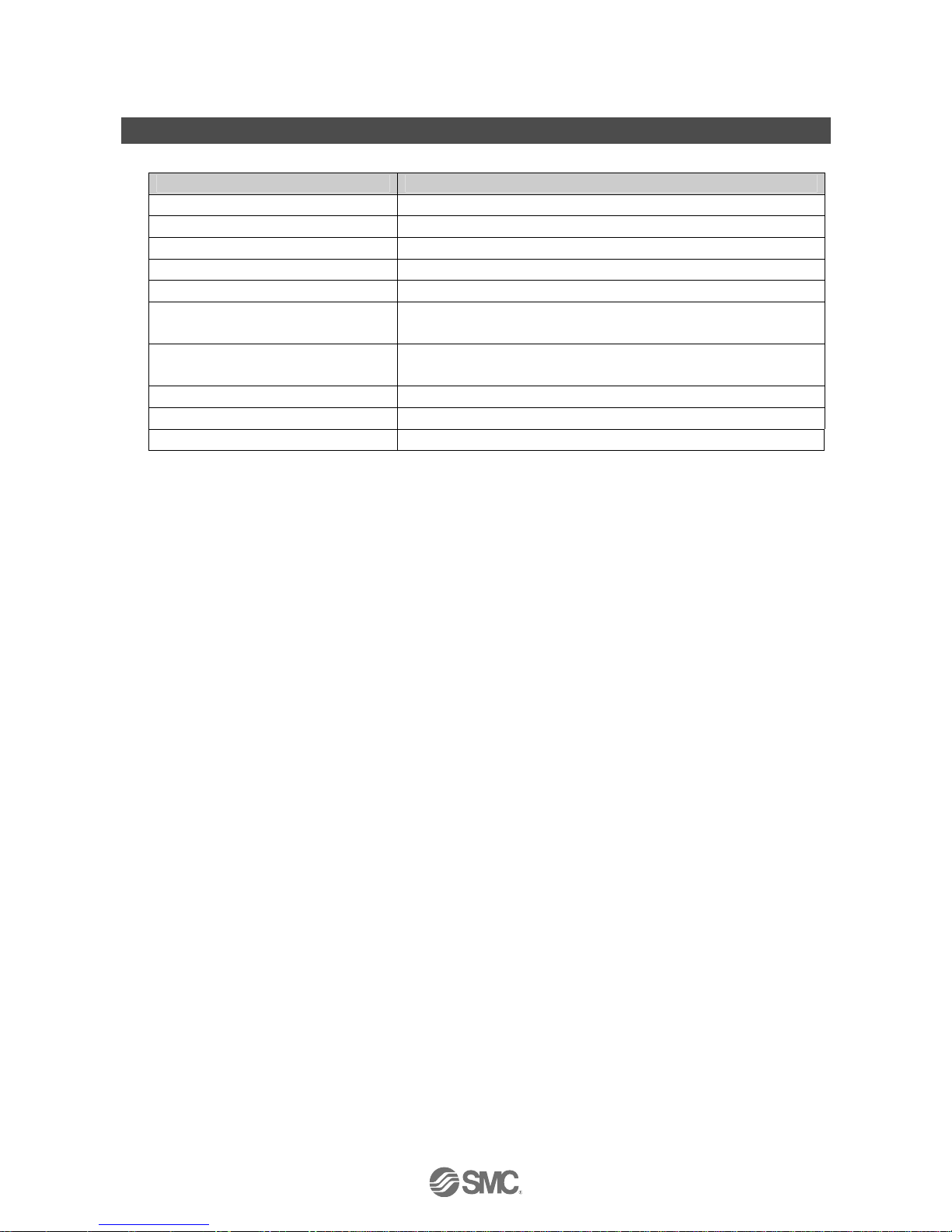
Common Specifications
•EX510 series common specifications
Item Specification
Rated voltage 24 VDC
Allowable instantaneous electrical stop 1 msec. or less
Enclosure IP20
Applicable standard UL/CSA, CE
Withstand voltage 500 VAC 1 minute (between FG and external terminal block)
Insulation resistance
10 MΩ or more
(500 VDC is given between FG and external terminal block)
Ambient temperature
Operating: -10 to 50
o
C
Storage: -20 to 60
o
C
Ambient humidity 35 to 85%RH (No dew condensation)
Operating atmosphere No corrosive gas
Pollution degree Pollution degree 3 ∗
∗: This product is IP20 rated.
When operating this product in a pollution degree 3 environment, mount it onto an IP54 rate or higher controller board etc.
-13-
No.EX##-OMI0001-E
EX510 GW unit
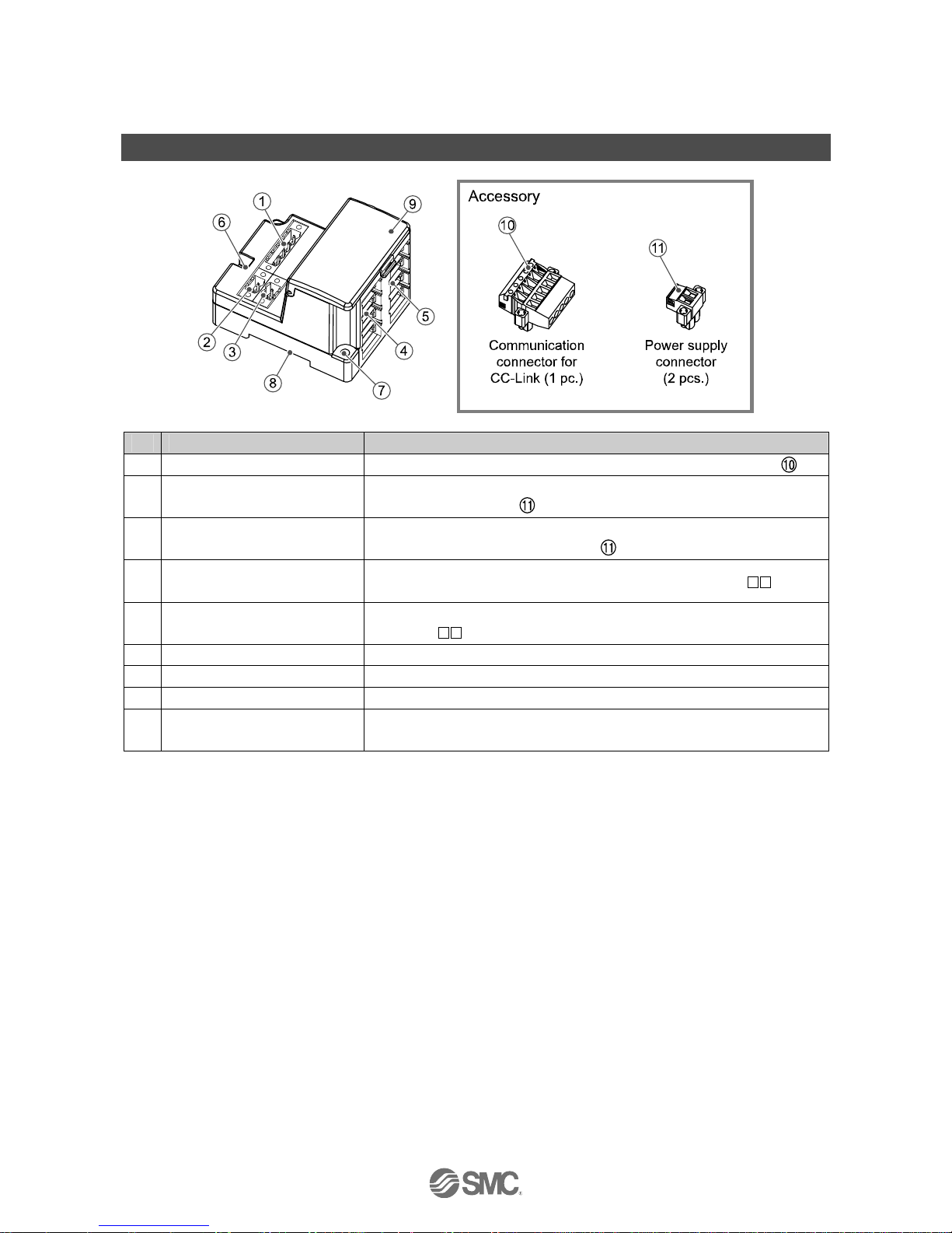
Summary of Product Parts
No. Element Description
1 Communication socket (BUS)
Connect to CC-Link line with a communication connector for CC-Link (
).
2 Power supply socket (PWR(V))
Supplying power for output instruments such as a solenoid valve with a
power supply connector (
).
3 Power supply socket (PWR)
Supplying power for controlling GW and for input instruments such as a
sensor with a power supply connector (
).
4
GW unit side branch connector
(for input)
Connecting an Input unit etc. by using branch cables (EX510-FC
).
5
GW unit side branch connector
(for output)
Connecting an SI unit (manifold valve) etc. by using branch cables
(EX510-FC
).
6 Ground terminal (FG) Used for grounding.
7 Mounting hole Used when an unit is mounted with two M4 screws.
8 DIN rail mounting slot Used when an unit is mounted to DIN rail.
9 Display/switch setting part
Switch setting such as LED display in unit state, transmission speed, and
occupied station number.
-14-
No.EX##-OMI0001-E
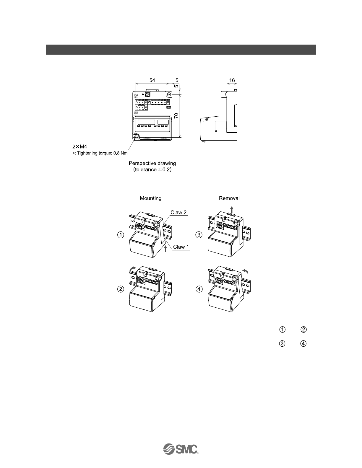
Mounting and Installation
■Installation
•Screw installation
•DIN rail installation
Put claw 1 of the body under DIN rail and push it upward. Push down Claw 2 to the opposite rail until the
claw clicks securely on to rail. (Mounting procedure
and )
For removing, lever up the DIN rail fixing plate of the body with a flat blade screwdriver, and remove it by
tilting Claw 2 side forward. (Removal procedure
and )
-15-
No.EX##-OMI0001-E
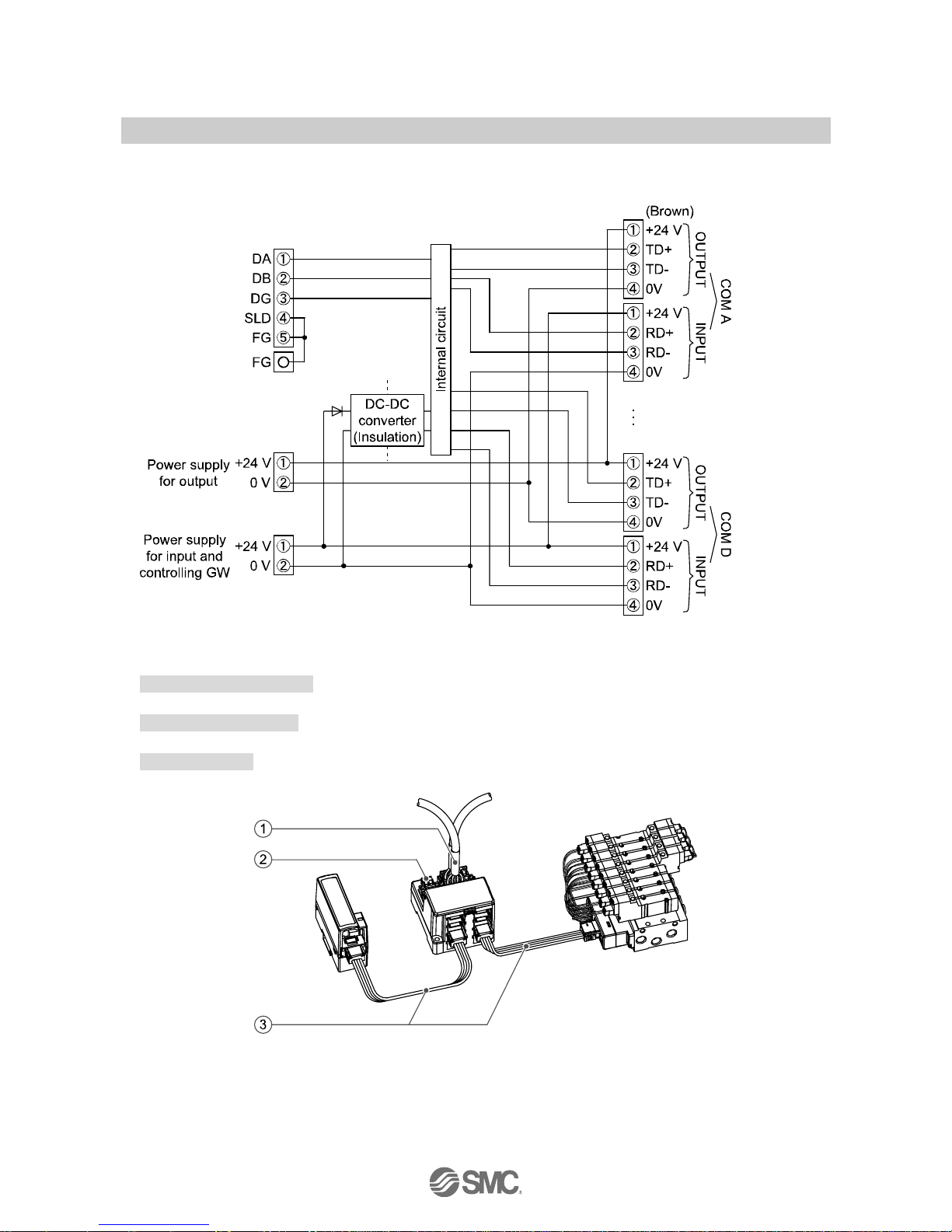
■Wiring
•Internal circuit and wiring
The wirings are described in the following order.
1. Communication wiring: Connection with CC-Link.
↓
2. Power supply wiring: Connections of power supplies for output and input devices and controlling GW.
↓
3. Branch wiring: Connection from GW unit to SI unit or Input unit.
-16-
No.EX##-OMI0001-E
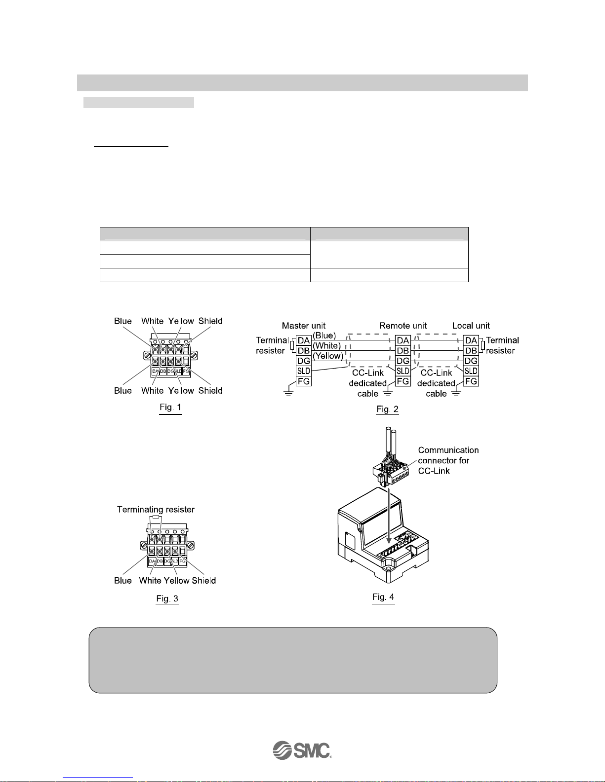
1. Communication wiring
The method to connect a CC-Link detected cable and a GW unit CC-Link communication connector is
shown below.
Connecting cable
•Make sure to connect the signal cables to designated pins (Refer to Fig. 1).
And tighten the connector surely to 0.5 to 0.6 Nm tightening torque.
•Make sure to connect "terminating resistor" between "DA"-"DB" to the units at the both ends of the
system.
(Refer to Fig. 3)
•The connected terminating resistor differs depending on used cable in system.
See the table below.
Cable type Terminal resistor
CC-Link dedicated cable
CC-Link dedicated cable compatible with Ver.1.10
110 Ω 1/2 W (brown, brown, brown)
CC-Link dedicated high performance cable 130 Ω 1/2 W (brown, orange, brown)
•Refer to Fig. 4 about how to connect to the unit.
Tighten the connector securely to 0.5 to 0.6 Nm tightening torque.
NOTE
1. CC-Link dedicated high performance cable cannot be mixed with other cables (CC-Link
dedicated cable, CC-Link dedicated cable compatible with Ver.1.10).
If mixed, normal transmission of data cannot be assured.
2. Connect the shield line of CC-Link dedicated cable to "SLD" of each unit.
-17-
No.EX##-OMI0001-E
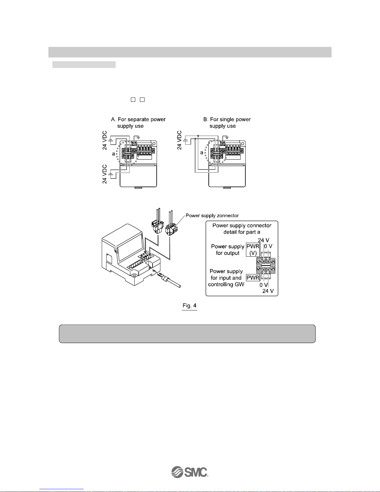
2. Power supply wiring
Connect power supply wiring to the two power supply 2-pin connectors. Power supply consists of
2 systems, but they it can be used with both of single power supply and separate power supplies.
Also, other units do not need individual power supply. Make sure of connection with the designated pin.
Tighten the connector securely to 0.5 to 0.6 Nm tightening torque. Refer to Fig. 4 about how to connecting.
When SI unit etc. (EX510-S 0 ) is used besides the external power supply type Output unit, it is
necessary to supply power for output to the GW unit and the Output unit.
NOTE
Ground the FG terminal.
 Loading...