

SMC Networks EX500-IE1, EX500-IB1 Installation & Maintenance Manual
Installation & Maintenance Manual
Reduced wiring system
EX500 Series Input Unit
EX500-IB1
EX500-IE
Indicates a potentially hazardous situation that
could result in death or severe injury if you do
not follow instructions.
Read this manual and follow its instructions. Signal words such as
WARNING, CAUTION and NOTE will be followed by important safety
information that must be carefully reviewed.
Gives you helpful information.
IMPORTANT MESSAGES
The body of unit and this manual contain the essential information for the
protection of users and others from possible injury and property damage
and to ensure correct handling.
Please check that you fully understand the definitions of the following
messages ( symbols ) before going on to read the body of this manual,
and always follow the instructions.
Please also read the instruction manuals etc. of related machines and
understand the contents before use.
Do not disassemble,
modify ( including modification of printed circuit board ) or
repair.
Otherwise injury or failure can result.
Do not operate beyond specification range.
Otherwise fire, malfunction or damage to the reduced wiring system can
result.
Confirm the specifications before operation.
Do not operate in atmosphere of
flammable/explosive/corrosive gas.
Otherwise fire, explosion or corrosion can result.
This reduced wiring system is not explosion-proof type.
Indicates a potentially hazardous situation that, if
not avoided, may result in minor injury or
moderate injury.
For use in interlock circuit:
• Provide double interlock system by adding different type
of protection
( such as mechanical protection ).
• Check that the interlock circuit is working normally.
Otherwise accident caused by malfunction can result.
Before performing maintenance:
• Turn off power supply.
• Stop air supply, exhaust compressed air in piping, and
confirm the release to atmosphere.
Otherwise injury can result.
Conduct proper functional inspection after completing
maintenance.
In the case of abnormality such as unit does not work normally, stop the
operation. Otherwise safety cannot be assured due to unintended
malfunction.
Provide grounding to improve safety and noise resistance of
reduced wiring system.
Provide grounding as close to the unit as possible to shorten distance for
grounding.
NOTE
H
andling precautions
Use the following UL-recognized DC power supply to combine with.
1. UL508-compatible limited voltage/current circuit
A circuit using the secondary coil of an insulating transformer that meets
following conditions as power source.
• Maximum voltage ( at no load ): 30Vrms ( 42.4Vpeak ) or below
• Maximum current: ( 1 ) 8A or less ( including when short-circuited )
( 2 ) When limited by the circuit protector ( such as
fuse ) having the following rating.
2. UL1310-compatible Class 2 power supply unit or circuit of max. 30Vrms
( 42.4Vpeak ) or less using a UL1585-compatible Class 2 transformer as
power source. ( Class 2 circuit )
Follow the instructions given below when handling your
reduced wiring system. Otherwise a damage or failure to cause
a malfunction can result.
• Operate the reduced wiring system at the specified voltage.
• Reserve space for maintenance.
• Do not remove any name plate or label.
• Do not drop, hit or apply an excessive shock to the unit.
• Follow the specified tightening torque.
• Do not apply any excessive force to cables by repeated bending, tensioning
or placing a heavy object on the cables.
• Connect wires and cables correctly.
• Do not perform any wiring work while the power is on.
• Do not use the reduced wiring system on the same wiring route as the
power line or high voltage line.
• Confirm the insulation of wiring.
• Perform the power supply wiring by dividing into two lines ---- one is for
power supply for output and the other is for power supply for input and
controlling GW/SI.
• Take sufficient measures against noise such as noise filter when
incorporating the reduced wiring system into a machine or equipment.
• Mount a terminal plug or a waterproof cap on each unused M12 connector
for input/output
( communication connector, communication ports A - D, and power supply
for input and controlling GW/SI ).
• Take sufficient shielding measures when operating the product in any of the
following places.
( 1 ) A place where noise due to static electricity etc. is generated
( 2 ) A place of high electric field strength
( 3 ) A place where exposure to radioactivity is possible
( 4 ) A place near power cable
• Do not operate the product in a place where there is a source of surge.
• Use a surge absorbing element built-in type to directly drive the load that
generates surge voltage such as solenoid valve.
• Prevent any foreign matter such as remnant of wires from getting inside the
product when opening the station number switch protective cover.
• Install the reduced wiring system in a place free from vibration and impact.
• Operate the product in the specified ambient temperature range.
• Do not use in a place to be affected by the radiant heat from a surrounding
heat source.
• Perform the maintenance regularly.
•
Conduct an appropriate functional inspection after completing the maintenance.
• Do not use chemicals such as benzin and thinner to clean the product.
Outline with Dimensions (in mm
)
Safety Instructions (continue)
Safety Instructions
W
hen only input blocks for M8 connector are connected
44.2
39.7
L3
(L4)
5
L1
L2 ( Rail mounting pitch: 12.5 )
DIN Rail
35
49
32.2
(7.5)
When only input blocks of 8-point-integrated type are
connected
L
1 [mm]: Rail length
L
2 [mm]: Mounting pitch
L3 [mm]:
Manifold length
L4 [mm]
Stations 1
When only input blocks for M12 connector are connected
(L4)
5
L3
L1
L2 ( Rail mounting pitch: 12.5 )
60
46.9
DIN Rail
44.2
35
32.2
(7.5)
2
345678
9
8
110.5 123 135.5 148 160.5 173 185.5
87.5
100 112.5 125 137.5 150 162.5 175
74
8
6 98 110 122 134 146 158
12
12 12.5 12.5 13 13 13.5 13.5
L1 [mm]: Rail length
L2 [mm]: Mounting pitch
L3 [mm]:
Manifold length
L4 [mm]
Stations 1
234 567 8
110.5
123 148 173 185.5 210.5 223 248
100
112.5 137.5 162.5 175 200 212.5 237.5
82
102 122 142 162 182 202 222
12
12 12.5 12.5 13 13 13.5 13.5
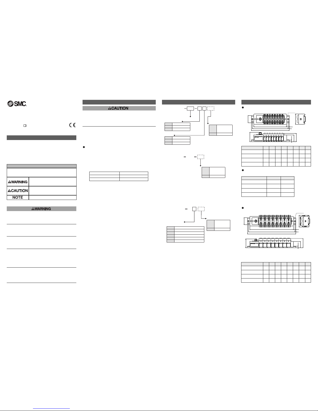
Model Indication Method
EEX500 IB1 E
Connector type
Input Unit Specification
8
E
T
M
M8 connector
M
12 connector
M8, M12 mixed
GW Unit compalible
Nil
-X1
D
eviceNet
P
ROFIBUS-DP
C
C-Link
Remote I/O(RIO)
Stations
1
8
1 station
8 stations
...
...
EX500 IB1
GW Unit compalible
Nil
-
X1
D
eviceNet
PROFIBUS-DP
C
C-Link
Remote I/O(RIO)
EX500 IE 1
Connector type
Input specification
1
2
3
4
5
6
M8 connector, PNP
M8 connector, NPN
M12 connector, PNP
M12 connector, NPN
8 point unit, M8 connector, PNP
8 point unit, M8 connector, NPN
GW Unit compalible
Nil
-X1
DeviceNet
PROFIBUS-DP
CC-Link
Remote I/O(RIO)
EX500-TFI70GB-A
L1 [mm]: Rail length
L2 [mm]: Mounting pitch
L3 [mm]: Manifold length
L4 [mm]
S
tations
1
2
135.5
185.5
125
175
110
158
12.5
13.5
No-Load Voltage (Vpeak) Max. Current Rating ( A )
0 to 20 [V] 5.0
20 [V] to 30 [V] 100/peak voltage
Installation ( unit : mm )
Wiring
Connect each connector of Input unit, input
blocks, and end block
( portion indicated by arrow in the figure to the
right ).
Holding with hands so that there will be no gap
between blocks, place the jointed unit and
blocks on DIN rail.
Tighten the bolts of Input unit and end block to
secure the jointed unit and blocks to DIN rail.
Be sure to tighten the bolts by proper
tightening torque.
( Tightening torque: 0.6Nm )
B
ranch wiring
For wiring method, refer to subsection "Wiring" in the Instruction Manual of
EX500.
To input devices such as sensor, the power is supplied through the branch
wiring ( branch cable with M12 connector ). Therefore, there is no need to
supply the power to them individually.
S
ensor connector "1"
Sensor connector "0"
M12 Block
1133
4
2
24
key
key
0
1
Input "0" (n) side Input "1" (n+1) side
Input "1" (n+1)
Input "0" (n)
Sensor wiring
Connect sensors to the
sensor connectors of input
block.
Pin layout of sensor connector
M8 connector ( 3-pin socket )
M
12 connector ( 4-pin socket )
Power supply
( 24VDC )
P
ower supply ( 0V )
Input
Power supply
( 24VDC )
(
Input ) ( Note )
Power supply ( 0V )
Input
1
2
4
3
1
4
3
Note: Internal wiring of M12 input block and key position for mounting sensor connector.
• No. 2 pins of M12 input block
connectors are wired to each other’s
sensor signal input pins ( No. 4 pins )
internally.
• This wiring enables direct input of
signals from two points combined into
one cable through concentric
connector etc.
• When connecting sensors, confirm the
specification of output signal carefully.
Otherwise malfunction can result.
• The key position for mounting sensor
connector is as shown to the right.
Consider this key position when
selecting sensor.
NOTE
Mount a waterproof cap on each unused connector of Input unit. The
proper use of waterproof cap can achieve IP65 Enclosure. The waterproof
caps are delivered together with each input block as accessories.
( Tightening torque: 0.05Nm for M8 and 0.1Nm for M12 )
Correspondence between input number and input block
Input block up to 8 can be connected ( 16 points ).
Input numbers are 0 - 15 from Input unit side.
0
010101010101010
1
2468
10
Unità d’entrata
12 14
13579
11 13 15
Display
S
ettings for display
Power LED
Indicator LED
Power
LED
Lights on: Power for input and controlling GW is supplied.
Flashing: Under short circuit protection ( abnormal status ).
A
s the short circuit protective function is operating,
the power is not supplied.
To cancel flashing, turn off and return the power to
GW unit.
Lights off: Power for input and controlling GW is not supplied.
Indicator
L
ED
L
ights on: Sensor signal input ON ( logical "1" )
Lights off: Sensor signal input OFF ( logical "0" )
Display Description
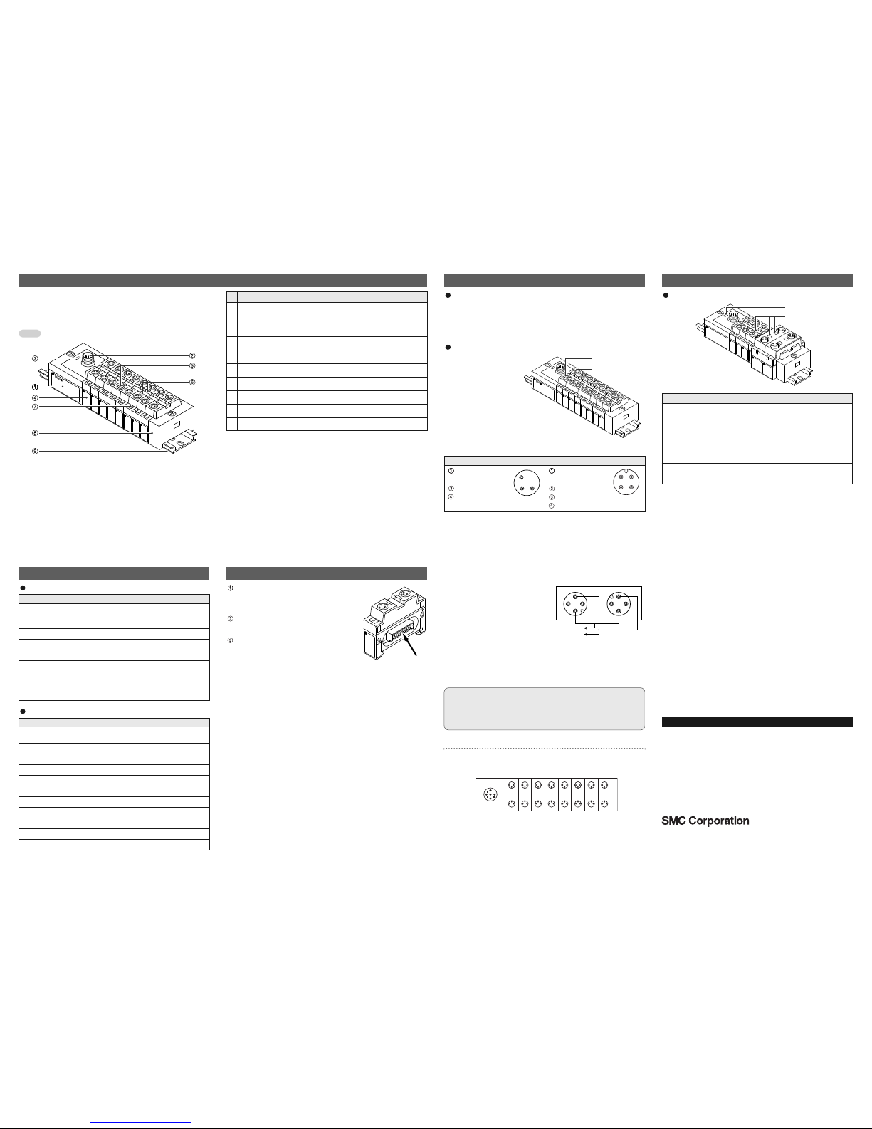
Names and Functions of individual parts
The Input unit manifold consists of Input unit, input block (s), end block
and DIN rail.
The input block up to 8 can be connected ( 16 points ).
Any combination of input blocks ( for M8 connector, M12 connector and
8-point-integrated type ) is acceptable.
Input unit1
N
ote1: For wiring method, refer to subsection "Wiring" in this manual.
N
ote2: For display, refer to "Display" in this manual.
Unit to communicate with GW unit or SI unit.
Communication
connector
2
To be connected with branch cables from GW
unit or SI unit ( branch cable with M12
connector ) ( Note1 )
Power LED3 Indicates the power supply status. ( Note2 )
Input block
4
Unit for sensor signal input.
Sensor connector5 Connects with sensor. ( Note1 )
Indicator LED6 Indicates sensor signal status. ( Note2 )
Marker7 To be used for writing input No. etc.
End block8 Composes the end of Input unit manifold.
D
IN rail9 To be mounted with Input unit manifold.
Part name
No.
A
pplication
Figure shows the configuration when only input blocks for M8 connector
are connected.
Do not mix sensor input specifications ( PNP and NPN ).
Note
Specification
Specifications for Input unit
Connected block
Current source type input block ( PNP input
block ) or Current sink type input block ( NPN
input block )
Connected block stations
Max. 8 blocks
Supply voltage for block 24VDC
Supply current for block
Current consumption
Max. 0.65A
100mA or less ( at rated voltage )
Short circuit protection
Operates at 1A Typ. ( Cuts power supply. )
Can be reset by returning the power after
cutting the power supply to input and control
section of GW unit.
Item Specification
Applicable sensor
Current source type
( PNP output )
Current sink type
( NPN output )
No. of input points 2 points/8 points ( for M8 connector only )
Rated voltage 24VDC
Logical "1" input voltage 15V - 26.4V 0V - 8V
Logical "0" input voltage 0V - 5V 19V - 26.4V
Logical "1" input current 5mA Typ. -5mA Typ.
Logical "0" input current 1.5mA
Input delay time 1msec. or less
Indicator LED Green LED
Insulation
Supply current to sensor
N/A
Max. 480mA/Input unit manifold
-1.5mA
Item Specification
Specifications for input block
EX500-TFI70GB-A
AUSTRIA (43) 2262 62280 NETHERLANDS (31) 20 531 8888
BELGIUM (32) 3 355 1464 NORWAY (47) 67 12 90 20
CZECH REP.
(420) 541 424 611
POLAND (48) 22 211 9600
DENMARK (45) 7025 2900 PORTUGAL (351) 21 471 1880
FINLAND (358) 207 513513 SLOVAKIA (421) 2 444 56725
FRANCE (33) 1 6476 1000 SLOVENIA (386) 73 885 412
GERMANY (49) 6103 4020 SPAIN (34) 945 184 100
GREECE (30) 210 271 7265 SWEDEN (46) 8 603 1200
HUNGARY (36) 23 511 390 SWITZERLAND (41) 52 396 3131
IRELAND (353) 1 403 9000 UNITED KINGDOM (44) 1908 563888
ITALY (39) 02 92711
URL http://www.smcworld.com (Global) http://www.smceu.com (Europe)
Specifications are subject to change without prior notice from the manufacturer.
© SMC Corporation All Rights Reserved.
Contact
 Loading...