

Page 1
Reduced wiring system
EX500-GDN1
Instruction Manual
DeviceNet Compatible GW Unit
URL http://www.smcworld.com
Page 2

Thank you for purchasing the SMC reduced wiring system EX500 series.
Please read this instruction manual carefully and understand the contents before
use so that you can operate this unit safely and correctly.
Please keep this manual handy for future reference.
SAFETY ..........................................................................................................2
Product Summary............................................................................................5
EX500
Part Names...................................................................................................6
Dimensions ...................................................................................................7
Installation.....................................................................................................7
Specification..................................................................................................8
Wiring..........................................................................................................11
Display/Switch setting.................................................................................18
SI Unit
Part Names.................................................................................................20
Dimensions .................................................................................................21
Mounting/Wiring..........................................................................................22
Specification................................................................................................23
Display ........................................................................................................24
Input Unit Manifold
Part Names.................................................................................................25
Dimensions .................................................................................................26
Installation...................................................................................................27
Specification................................................................................................28
Wiring..........................................................................................................29
Display ........................................................................................................30
EX9 Series General Purpose Output Block
Part Names.................................................................................................31
Dimensions .................................................................................................32
Mounting .....................................................................................................33
Wiring..........................................................................................................34
Specification................................................................................................36
Display .......................................................................................................37
Option............................................................................................................38
Troubleshooting.............................................................................................40
OPERATOR
This instruction manual has been written for those who have knowledge of
machines and equipments that use reduced wiring system as well as the
sufficient knowledge to assemble, operate, and maintain such devices.
Before performing assembly, operation and/or maintenance, please read
this manual carefully and understand the contents.
Contents
To facilitate recycling, this
manual is printed using
biodegradable soy ink, which
can easily be de-inked.
This manual is printed in the
"non-water system", which does
not output toxic liquid waste.
Page 3
2 3
SAFETY
The body of unit and this manual contain the essential information for the protection of
users and others from possible injury and property damage and to ensure correct
handling.
Please check that you fully understand the definitions of the following messages
( symbols ) before going on to read the body of this manual, and always follow the
instructions.
Please also read the instruction manuals etc. of related machines and equipments and
understand the contents before use.
IMPORTANT MESSAGES
Indicates a potentially hazardous situation that could result in
death or severe injury if you do not follow instructions.
Read this manual and follow its instructions. Signal words such as WARNING,
CAUTION and NOTE will be followed by important safety information that must be
carefully reviewed.
Indicates a potentially hazardous situation that, if not avoided,
may result in minor injury or moderate injury.
Gives you helpful information.
NOTE
Do not disassemble,
modify ( including modification of printed circuit board ) or repair.
Otherwise injury or failure can result.
Do not operate beyond specification range.
Otherwise fire, malfunction or damage to the reduced wiring system can result.
Confirm the specifications before operation.
Do not operate in atmosphere of flammable/explosive/corrosive gas.
Otherwise fire, explosion or corrosion can result.
This reduced wiring system is not explosion-proof type.
For use in interlock circuit:
Provide double interlock system by adding different type of protection
( such as mechanical protection ).
Check that the interlock circuit is working normally.
Otherwise accident caused by malfunction can result.
Before performing maintenance:
Turn off power supply.
Stop air supply, exhaust compressed air in piping, and confirm the release
to atmosphere.
Otherwise injury can result.
Conduct proper functional inspection after completing maintenance.
In the case of abnormality such as unit does not work normally, stop the operation.
Otherwise safety cannot be assured due to unintended malfunction.
Provide grounding to improve safety and noise resistance of reduced wiring
system.
Provide grounding as close to the unit as possible to shorten distance for grounding.
1. UL508-compatible limited voltage/current circuit
A circuit using the secondary coil of an insulating transformer that meets following conditions
as power source.
Maximum voltage ( at no load ):30Vrms ( 42.4Vpeak ) or below
Maximum current: ( 1 ) 8A or less ( including when short-circuited )
( 2 ) When limited by the circuit protector ( such as fuse )
having the following rating.
2. UL1310-compatible Class 2 power supply unit or circuit of max. 30Vrms ( 42.4Vpeak ) or less
using a UL1585-compatible Class 2 transformer as power source. ( Class 2 circuit )
No-Load Voltage ( Vpeak ) Max. Current Rating ( A )
0 to 20 [V] 5.0
Above 20 [V] to 30 [V] 100/peak voltage
Handling precautions
Use the following UL-recognized DC power supply to combine with.
Page 4
4 5
SAFETY ( continued )
Follow the instructions given below when handling your reduced wiring system.
Otherwise a damage or failure to cause a malfunction can result.
Operate the reduced wiring system at the specified voltage.
Reserve space for maintenance.
Do not remove any name plate or label.
Do not drop, hit or apply an excessive shock to the unit.
Follow the specified tightening torque.
Do not apply any excessive force to cables by repeated bending, tensioning or placing a
heavy object on the cables.
Connect wires and cables correctly.
Do not perform any wiring work while the power is on.
Do not use the reduced wiring system on the same wiring route as the power line or high
voltage line.
Confirm the insulation of wiring.
Perform the power supply wiring by dividing into two lines ---- one is for power supply for output
and the other is for power supply for input and controlling GW/SI.
Take sufficient measures against noise such as noise filter when incorporating the reduced
wiring system into a machine or equipment.
Mount a terminal plug or a waterproof cap on each unused M12 connector for input/output
( communication connector, communication ports A - D, and power supply for input and
controlling GW/SI ).
Take sufficient shielding measures when operating the product in any of the following places.
( 1 ) A place where noise due to static electricity etc. is generated
( 2 ) A place of high electric field strength
( 3 ) A place where exposure to radioactivity is possible
( 4 ) A place near power cable
Do not operate the product in a place where there is a source of surge.
Use a surge absorbing element built-in type to directly drive the load that generates surge
voltage such as solenoid valve.
Prevent any foreign matter such as remnant of wires from getting inside the product when
opening the station number switch protective cover.
Install the reduced wiring system in a place free from vibration and impact.
Operate the product in the specified ambient temperature range.
Do not use in a place to be affected by the radiant heat from a surrounding heat source.
Set the DIP switch and rotary switch by using a sharp-pointed watchmakers screwdriver etc.
Perform the maintenance regularly.
Conduct an appropriate functional inspection after completing the maintenance.
Do not use chemicals such as benzin and thinner to clean the product.
Product Summary
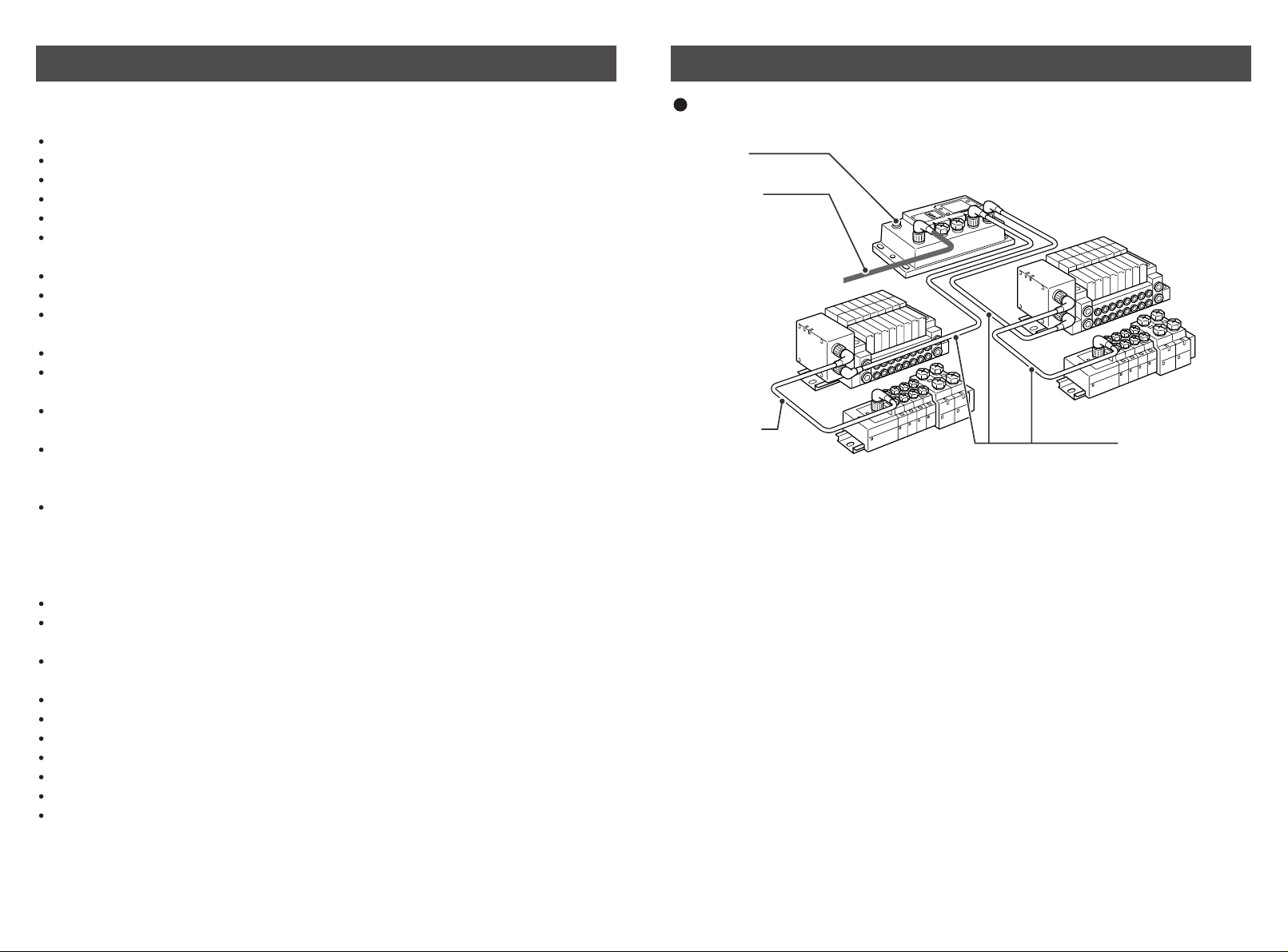
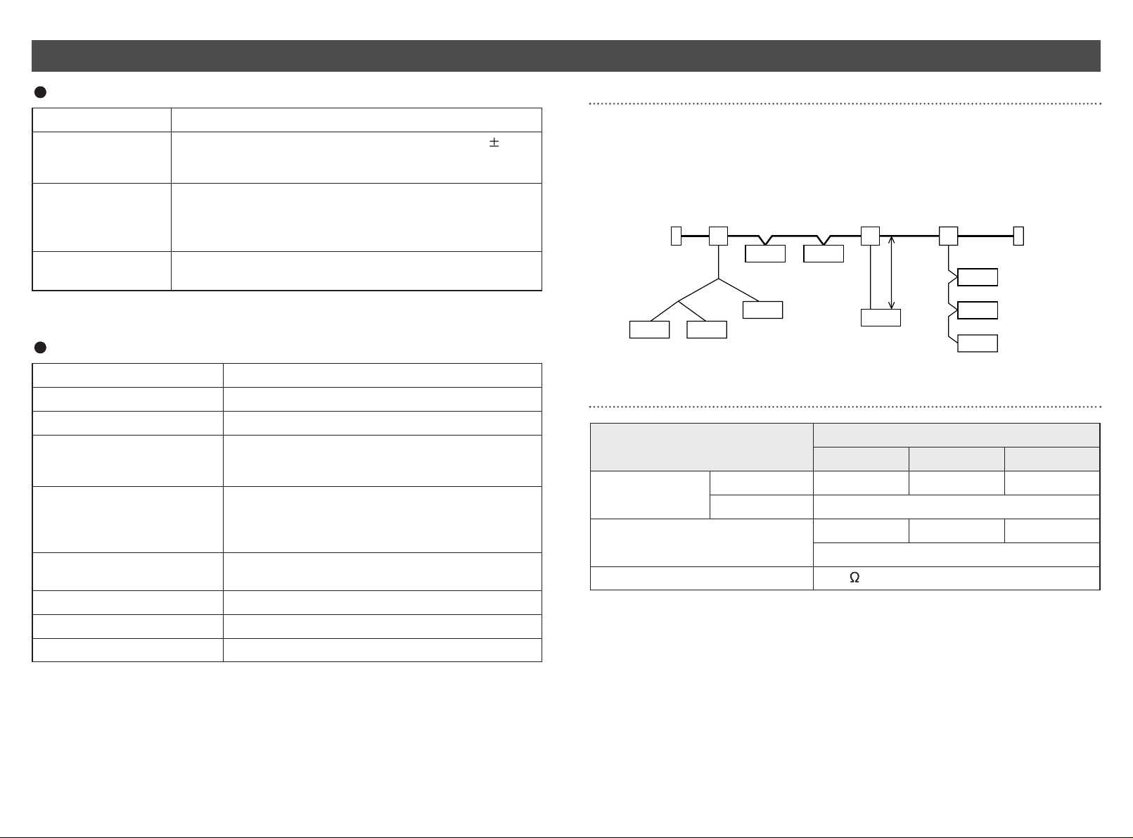
System configuration
The reduced wiring system is connected to various kinds of fieldbus realizes the
reduced wiring and decentralized installation of I/O devices . The signals to/from
fieldbus are exchanged by GW unit, and the signals to/from decentralized I/O devices
are collected and delivered by GW unit.
The maximum number of connections of manifold valve/Input unit manifold is
16/branch x 4 branches = 64 points each for output and input.
As the cables with connectors are used for all wirings among devices, the system
complies with the IP65 environment.
DeviceNet
communication connector
Power supply
connector cable
( DC24V for solenoid
valves/output, DC24V for
input and controlling GW/SI )
Manifold valve
with SI unit
( SV/VQC series )
Branch cable
with M12 connector
Input unit manifold
GW unit
Manifold valve
with SI unit
( SV/VQC series )
Input unit
manifold
Branch cable
with M12 connector
Page 5
6 7
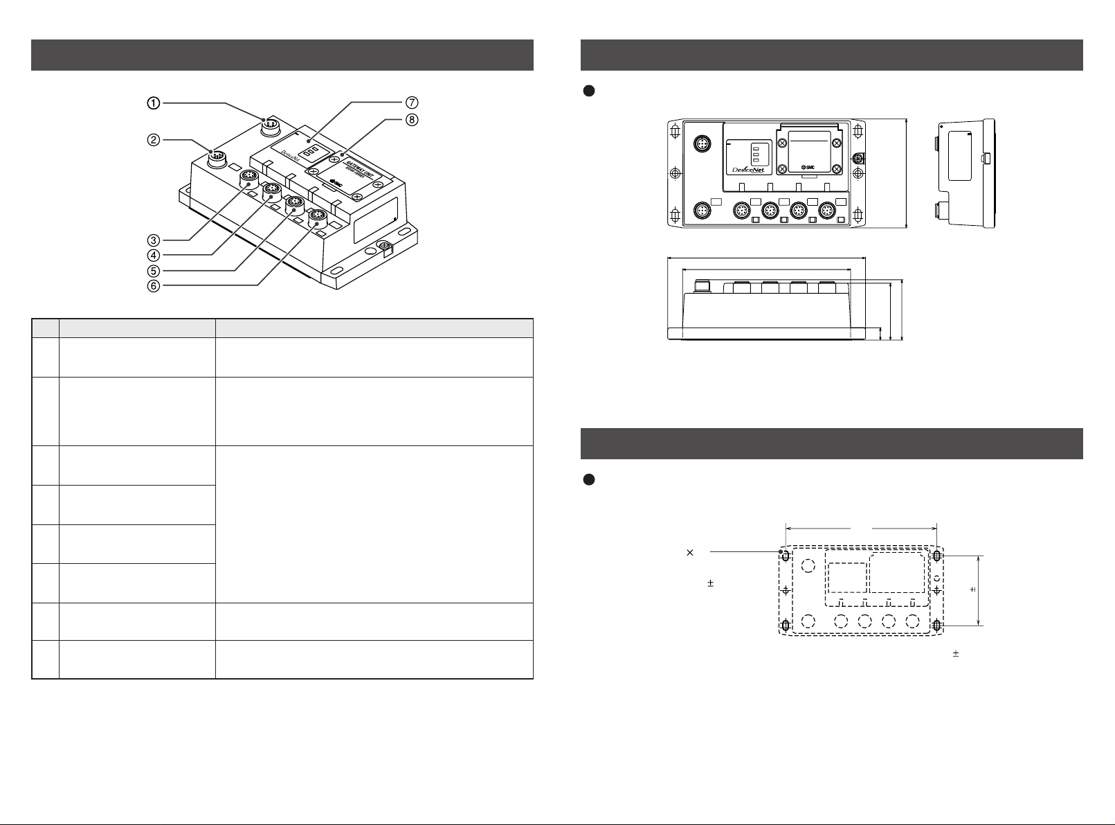
EX500 Part Names
M
S
N
S
S
O
L
B
U
S
EX500-GDN1
Communication
connector
1
2
3
4
5
6
7
8
Note1: For wiring method, refer to subsection "Wiring" ( page 11 ) of section "EX500" in this
manual.
Note2: For display and setting method, refer to subsection "Display/Switch Setting" ( page 18 )
of section "EX500" in this manual.
Power supply connector
Communication port A
( COM A )
Communication port B
( COM B )
Communication port C
( COM C )
Communication port D
( COM D )
Display
Connect with DeviceNet line. ( Note 1 )
Name
No.
Application
Supply power for output devices such as solenoid
valve, for input devices such as sensor, and for
controlling GW/SI by using power supply connector
cable. ( Note1 )
Display the power supply status and communication
status with PLC. ( Note2 )
Station number switch
protective cover
Set address and data rate by using the switches
under this cover. ( Note2 )
Connect SI unit ( manifold valve ) or Input unit by
using branch cable with M12 connectors. ( Note1 )
Dimensions ( unit: mm )
EX500-GDN1
24VDC COM A COM B COM C COM D
BUS
MS
NS
SOL
88
10
46
48.8
136
160
GATEWAY UNIT
EX500 SERIES
PE
EX500 body
Installation ( unit: mm )
Thread mounting
Secure at four positions with screws with head diameter of 5.2 or more and thread
length of 15mm or more.
148
4 M5
Tightening torque :
*
(1.5 0.2 ) Nm
68 5
Cutout Dimensions for Mounting ( Tolerance : 0.2 )
Page 6
8 9
Specification
Basic specifications
Rated voltage DC24V
Range of power
supply voltage
Power supply for input and controlling GW/SI: DC24V 10%
Power supply for output: DC24V+10%/-5% ( Voltage drop
warning at around 20V )
Rated current Power supply for input and controlling GW/SI: 3.0A
Inside GW unit: 0.2A
Input device and SI control section: 2.8A
Power supply for solenoid valves and output: 3A
Number of input/
output points
Input point: max. 64/Output point: max 64
Higher-level bus
Protocol
DeviceNet Release 2.0
Slave ( slave station ) type
MAC ID setting range
Group2 only server
0 - 63
Device information
Applicable message
I/O message size
Date rate
Vender code: 7 ( SMC Corp. )
Product type: 12 ( communication adapter )
Product code: 5001
Duplicate MAC ID check message
Group2 only unconnected explicit message
Explicit message
Poll I/O message
Input: 8 bytes
Output: 8 bytes
125kbps, 250kbps, 500kbps
Transmission distance
Insulation method
Refer to the next page.
Photocoupler
(
)
Transmission distance
Network length
Terminating
resistor
Node
NodeNode
Multi-branch
T-branch
Node
Terminating
resistor
Node
Node
Node
Trunk line
Multi-branch
Drop
line
Drop
line
Max.
6m
Drop line branch
Multi-
branch
Drop
line
Node Node
DeviceNet allows T-branch, multi-branch and drop line branch connections.
Total extended length of trunk line and drop lines depends on the date rate and the
thickness of communication cable. The connection type for EX500 series is
T-branch only.
Item
Maximum
network length
Total drop line length
Terminating resistor
Thick cable
Thin cable
Date rate ( kbps )
125 250 500
500m or less 250m or less 100m or less
100m or less
156m or less 78m or less 39m or less
Note: Maximum length per drop line is 6m.
121 , 1/2W ( brown/red/brown/black/brown )
Page 7
10 11
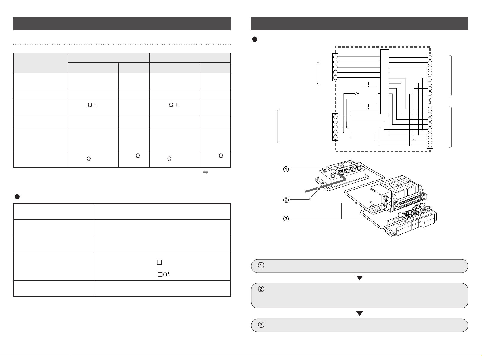
Wiring
Specification ( continued )
The wirings are described in the following order.
Communication wiring: Connection with DeviceNet
Power supply wiring: Connections of power supplies for
solenoid valves/output devices, and
for input devices and controlling GW/SI
Internal circuit
Branch wiring: Connection from GW unit to SI unit or Input unit
Lower-level bus
Number of branches for
input/output
4 branches ( 16 points/branch ) for input
4 branches ( 16 points/branch ) for output
Communication method Protocol: Dedicated for SMC
Speed: 750kbps
Branch current for input
( Note )
Max. 0.5 [A] per branch ( when SI unit and input
devices are connected )
Branch current for output Max. 0.65 [A] per branch
( when SI unit EX500-S 01 is connected )
Max. 0.75 [A] per branch
( when SI unit EX500-Q is connected )
Branch cable length 5m or less per branch
( total extended length: 10m or less )
Note: Total value of maximum current consumption and maximum load current of input devices
to connect.
1ft 0.3048m
Item
Conductor’s
cross-section area
Color
Impedance
Propagation delay (Max.)
Attenuation rate
(Max.)
Conductor
resistance (Max.)
Signal
0.82mm
2
1.65mm
2
0.20mm
2
0.33mm
2
Blue, white Red, black
1.36ns/ft
-
Blue, white Red, black
1.36ns/ft
-
125kHz: 0.29dB/ft
500kHz: 0.50dB/ft
1.00MHz: 0.70dB/ft
120 10%
(1MHz)
-
120 10%
(1MHz)
-
-
125kHz: 0.13dB/ft
500kHz: 0.25dB/ft
1.00MHz: 0.40dB/ft
-
Thick cable Thin cable
Power Signal Power
6.9 /1000ft
3.6
/1000ft
28 /1000ft
17.5
/1000ft
Cable specification
1
DRAIN
2
V
+
3
V
-
4
CAN H
CAN L
5
connector
Power
supply
connector
Communication
Power supply
for output
Power supply
for input and
controlling GW/SI
0V
+24V
0V
+24V
PE
1
2
3
4
5
DC-DC
converter
(insulation)
Internal circuit
1
2
3
4
5
6
7
8
1
2
3
4
5
6
7
8
RD+
RD TD+
TD +24V
0V
+24V
0V
RD+
RD TD+
TD +24V
0V
+24V
0V
COM A
COM D
Page 8

12 13
Wiring ( continued )
Communication wiring
Aligning the key groove with the communication connector
( 5-pin, plug ) of GW unit, plug the DeviceNet
communication cable ( socket ).
Tighten the lock nut on cable side by turning it
clockwise by hand.
Confirm that the connector portion does not move.
Pin layout and connection diagram of cable with DeviceNet communication connector
Cable connection
Connect the cable with DeviceNet communication connector to the communication
connector of GW unit.
21
5
34
Connect the communication cable with socket-type M12 connector to the
communication connector of GW unit.
2
43
5
1
Socket Connector Pin Layout
Connection of terminating resistor
To both ends of DeviceNet trunk line, be sure to connect terminating resistors.
For terminating resistor, refer to subsection "Specification" ( page 8 ) of section "EX500"
in this manual.
M12
14.9
EX500-AC0 -DN
Connection Diagram
DRAIN 1
V + 2
V
-
3 Black
CAN H
4 White
CAN L 5
Red
Blue
Core wire
Outside diameter
Sheath color
Cable specification
Signal wire AWG24 ( 41/0.08 ) Blue, white
Power wire
Drain wire
7
Light blue
AWG22 ( 19/0.16 )
AWG22 ( 19/0.16 )
Red, black
-
This cable is DeviceNet thin cable.
Note 1
Power supply wiring
Connect the power supply connector cable to the power supply connector of GW unit.
There are two types of cables different in connector shape ---- straight type and angle
type. With this cable, the power is supplied to the output devices such as solenoid valve,
and the input devices such as sensor, and for controlling GW/SI. Therefore, there is no
need to supply the power to other units individually.
When selecting the power supply, refer to "Handling precautions" ( page 3 ) in this manual.
Cable connection
Aligning the key groove with the power supply
connector ( plug ) of GW unit, plug the power supply
cable ( socket ).
Tighten the lock nut on cable side by turning it
clockwise by hand.
Confirm that the connector portion does not move.
Pin layout and connection diagram of power supply connector cable for ( unit: mm )
( Pin layout and connection diagram are common to all cables. )
2
43
5
1
Socket Connector Pin Layout
Straight connector Type Angle connector Type
EX500-AP -S EX500-AP -A
M12
M12
14.9
48
34
18
6
30 5
50
31.3
28.3
30 5
50
6
Pin No.
5
4
3
2
1
Cable color: Signal name
Brown: 0V ( for solenoid valves/output )
White: DC24V+10%/-5% ( for solenoid valves/output )
Blue: 0V ( for input and controlling GW/SI )
Black:
DC24V 10% ( power supply for input and controlling GW/SI )
Gray: Ground ( PE )
NOTE
Connect a ground cable of 100 or less to PE terminal.
( The DRAIN and PE terminal of DeviceNet are connected inside GW unit through
capacitor. )
Page 9

14 15
Wiring ( continued )
Separate wiring for power supply for solenoid valves/output and
for input and control of GW/SI
Both single power supply and two power supply systems can be adopted, however, the
wiring shall be made separately ( for solenoid valves/output and for input and controlling
GW/SI ) for either system.
24VDC
24VDC
Brown: 0V ( for solenoid valves/output )
White: DC24V ( for solenoid valves/output )
Gray: Ground ( PE )
Blue: 0V ( for input and controlling GW/SI )
Black: DC24V ( for input and controlling GW/SI )
Cable Part No. : EX500-AP -
24VDC
Brown: 0V ( for solenoid valves/output )
White: DC24V ( for solenoid valves/output )
Gray: Ground ( PE )
Blue: 0V ( for input and controlling GW/SI )
Black: DC24V ( for input and controlling GW/SI )
Cable Part No. : EX500-AP -
Power supply
connector
Power supply
connector
1
34
5
2
1
34
5
2
A. Two power supply system
B. Single power supply system
Branch wiring ( wiring to communication ports )
For wiring with solenoid valves or input devices, connect the branch cable with M12
connector to communication ports A - D.
There are two types of cables different in connector shape ---- straight type and angle
type. As each cable contains power supply wire, there is no need to supply the power to
solenoid valves or input devices individually.
Cable connection
Aligning the key groove with the
connector ( socket ) of GW unit, plug in
the cable ( plug ).
2
3
4
5
6
7
1
8
1
7
6
5
4
3
2
8
Socket Connector Pin Layout Plug Connector Pin Layout
Tighten the lock nut on cable side by
turning it clockwise by hand.
Confirm that the connector portion does
not move.
NOTE
Mount a waterproof cap on each unused connector of GW unit. The proper use of
waterproof cap can achieve IP65 Enclosure. ( Tightening torque: 0.1Nm for M12 )
Page 10

16 17
Wiring (continued )
For GW unit – Manifold valve – Input unit manifold configuration
Two communication connectors in SI unit and one communication connector in Input
unit are installed respectively.
To the communication connector ( C2 ) or ( 1 ) of SI unit, connect the branch cable with
M12 connector from GW. To the communication connector ( C1 ) or ( 0 ), connect the
branch cable with M12 connector from Input unit.
To the communication connector of Input unit, connect the branch cable with M12
connector from SI unit.
GW unit
Manifold valve with SI unit
( for SV/VQC series )
Connector (C1) / (0)
Branch cable
with M12 connector
Connector (C2) / (1)
Input unit manifold
NOTE
When no Input unit is connected
to the connector ( C1 ) or ( 0 ) of
SI unit, mount a terminal plug on
the connector.
For GW unit – Input unit manifold configuration
To the communication connector of Input unit, connect the branch cable with M12
connector from GW unit.
Branch cable
with M12 connector
GW unit
Input unit manifold
Type, pin layout and connection diagram of the branch cable with M12 connector ( EX500-AC - )
Manifold valve with SI unit
( for SV/VQC series )
L
M12
48
6
14.9
Straight Connector Type
EX500-AC -SSPS
52
16
M12
M12
Terminal plug
6
28.3
31.3
L
Angle Connector Type
EX500-AC -SAPA
L=300, 500, 1000, 3000, 5000 (mm)
M12
32.3
31.3
Page 11

SOL
NS
MS
BUS
GATEWAY UNIT
EX500 SERIES
COM A COM B COM C COM D
18 19
Display/Switch Setting
Settings for display
MS
NS
SOL
Lights on in green: Normal status.
Lights on in red: Fatal failure occurred.
Lights off: Offline/Power is OFF.
Blinks in green: Online/Communication is not established.
Lights on in green: Online/Communication is established.
Blinks in red: Minor communication error occurred.
Lights on in red: Fatal communication error occurred.
Lights on: Power is supplied to solenoid valves/output at specified
voltage.
Lights off:
Power is not supplied to solenoid valves/output at
specified voltage. ( Voltage dropped to lower than 20V. )
COM A
COM B
COM C
COM D
Lights on: COM A is receiving data.
Lights off: COM A has no received data.
Lights on: COM B is receiving data.
Lights off: COM B has no received data.
Lights on: COM C is receiving data.
Lights off: COM C has no received data.
Lights on: COM D is receiving data.
Lights off: COM D has no received data.
Display Description
NOTE
When connecting manifold valve only without connecting Input unit manifold, LEDs of
COM A - D do not light. To make them light, connect a terminal plug to the unused
connector of SI unit ( "C1" or "0" ).
Switch setting
Open the station number switch protective cover and set the switches with a
sharp-pointed watchmakers screwdriver etc.
NOTE
1. Be sure to turn off the power before setting the switches.
2. Be sure to set these switches before use.
3. After opening and closing the station number switch protective cover, tighten the
screws by proper tightening torque. ( Tightening torque: 0.6Nm )
Address setting switches
1 and 2 ( SW1 and SW2 )
These switches can set the node address.
SW1
0
1
2
3
4
5
9
8
7
6
SW2
0
1
2
3
4
5
9
8
7
6
SW1: Sets the second digit.
SW2: Sets the first digit.
110
Data rate setting switch (SW3)
This switch can set the data rate.
SW3
0
1
2
3
4
5
9
8
7
6
The settings of each switch are as shown in the table below:
( The initial settings are: SW1; 6, SW2; 3 and SW3; 0. )
00 0
0
0
...
...
...
...
...
1
2
1
2
63
64
99
63
PGM ( Note )
SW1 SW2 Node address
0 125kbps
1
2
250kbps
500kbps
3
...
9 PGM ( Note )
SW3 Data rate
Note: When PGM is selected, the node address or data rate will be set via DeviceNet network.
0
1
9
8
7
2
3
4
6
5
SW1
8
7
0
1
9
2
3
4
6
5
SW2
0
1
9
8
7
2
3
4
6
5
SW3
Page 12

20 21
SI Unit Part Names Dimensions ( unit: mm )
The SI unit is the unit to communicate with GW unit in combination with manifold valve.
It can be used with SV series valves and VQC series valves.
In addition, this unit is able to operate solenoid valves, relays. etc. in combination with
EX9 series general purpose output block. For how to use it, refer to section "EX9 Series
General Purpose Output Block" ( page 31 ) in this manual.
SI unit for
SV series
1. SI unit for SV series valves ( EX500-S 01 )
2. SI unit for VQC series valves ( EX500-Q )
Communication
connector "C1" or "0"
1 Connects the branch cable to Input unit ( branch cable
with M12 connector ). ( Note1 )
Communication
connector "C2" or "1"
2 Connects the branch cable from GW unit ( branch
cable with M12 connector ). ( Note1 )
Power LED3 Indicates the power supply status. ( Note2 )
Communication LED4
Indicates the communication status with GW unit: ( Note2 )
Name
No.
Application
Common to EX500-S 01/EX500-Q
Note1: For wiring method, refer to subsection "Wiring" ( page 11 ) of section "EX500" in this
manual.
Note2: For display, refer to "Display" ( page 24 ) in section "SI Unit" in this manual.
54.5
68.5
79.4
28.6
22.2
43.2
1. SI unit for SV series valves ( EX500-S 01 )
2. SI unit for VQC series valves
( EX500-Q 01 )
( EX500-Q 02 )
SI unit for
VQC series
( EX500-Q 01 )
PWR
COM
80.3
64.4
60
43.2
28
22.2
0
1
10.5
PWR
COM
66
64.4
84.8
80.3
series
36
0
60
43
22
13
10.5
1
44
Page 13

22 23
Mounting/Wiring Specification
The mounting and removing methods of SI unit are as shown below.
For branch wiring method, refer to subsection "Wiring" ( page 11 ) of section "EX500"
in this manual. As the power to output devices such as solenoid valve is supplied by
branch wiring ( branch cable with M12 connector ), there is no need to supply power
individually.
Note 1
For mounting/installation methods of solenoid valve, manifold, etc., refer to the
catalogs, instruction manuals, technical data, etc. of each valve series.
When connecting general purpose output block only, refer to subsection "Mounting"
( page 33 ) of section "EX9 Series General Purpose Output Block" in this manual.
Note 2
SI Unit for SV Series Valves ( EX500-S 01 )
M3 30: 4 pcs.
( Plus-minus slot
round head screw )
Supply/exhaust block
assembly
SI Unit for VQC Series Valves ( EX500-Q 01 )
Supply/exhaust block
assembly
M3 10: 2 pcs.
( Hexagon socket head cap
screw ( with spring washer ))
NOTE
Holding with hand so that there will be no gap between SI unit and Air supply/exhaust
block assembly, tighten the bolts. Be sure to tighten each bolt by specified tightening
torque. ( Tightening torque: 0.6Nm )
1. SI unit for SV series valve ( EX500-S 01 )
Connected block
Solenoid valve ( single, double )
Relay output module ( 1-point output, 2- point output )
Connected block
station
Double solenoid valve
Relay output module ( 2-point output )
Supply voltage for block
DC24V
Supply current for block
0.65A Max.
Current consumption 100mA or less ( at rated voltage )
Single solenoid valve
Relay output module ( 1-point output )
Max. 8 stations
Max. 16 stations
Item Specification
2. SI unit for VQC series valve ( EX500-Q )
Connected block
Solenoid valve ( single, double )
General purpose output block ( EX500-Q 02 only )
Connected block
station
Supply voltage for block
Supply current for block
Current consumption
Double solenoid valve
Item Specification
3. Applicable valve series
Cassette Tie-rod 40 50 63 80 100 125
Series
Manifold
Inner diameter of applicable cylinder tube ( mm )
Max. 8 stations
Single solenoid valve
General purpose output block
( EX500-Q 02 only )
Max. 16 stations
Max. 8 stations
DC24V
0.75A Max.
100mA or less ( at rated voltage )
SV1000
SV2000
SV3000
-
-
-
-
-
SV4000
VQC1000
VQC2000
VQC4000
For detailed specifications of solenoid valve and manifold, refer to the catalogs, instruction
manuals, technical data, etc. of each valve series.
Page 14

24 25
Display
Power LED
Communication LED
SI unit for SV series valves ( EX500-S 01 )
SI unit for VQC series valves ( EX500-Q )
Power LED Lights on: Power to solenoid valves/output is supplied at the
specified voltage.
Lights off: Power to solenoid valves/output is not supplied at
the specified voltage. ( Voltage dropped to lower
than 20V. )
Communication
LED
Lights on: Receiving data from GW
Lights off: No received data
Display Description
Input Unit Manifold Part Names
Common to EX500-S 01/EX500-Q
The Input unit manifold consists of Input unit, input block (s), end block and DIN rail.
The input block up to 8 can be connected ( 16 points ).
Any combination of input blocks ( for M8 connector, M12 connector and 8-pointintegrated type ) is acceptable.
Input unit1
Note1: For wiring method, refer to subsection "Wiring" ( page 29 ) of section "Input Unit
Manifold" in this manual.
Note2: For display, refer to "Display" ( page 30 ) in section "Input Unit Manifold" in this manual.
Unit to communicate with GW unit or SI unit.
Communication
connector
2
To be connected with branch cables from GW unit or
SI unit ( branch cable with M12 connector ) ( Note1 )
Power LED3 Indicates the power supply status. ( Note2 )
Input block4 Unit for sensor signal input.
Sensor connector5 Connects with sensor. ( Note1 )
Indicator LED6 Indicates sensor signal status. ( Note2 )
Marker7 To be used for writing input No. etc.
End block8 Composes the end of Input unit manifold.
DIN rail9 To be mounted with Input unit manifold.
Part name
No.
Application
Figure shows the configuration when only input blocks for M8 connector are connected.
Do not mix sensor input specifications ( PNP and NPN ) .
Note
Communication LED
Power LED
Page 15

26 27
Dimensions ( unit: mm )
When only input blocks for M8 connector are connected
When only input blocks of 8-point-integrated type are connected
L1 [mm]: Rail length
L2 [mm]: Mounting pitch
L3 [mm]:
Manifold length
L4 [mm]
98 110.5 123 135.5 148 160.5 173 185.5
87.5 100 112.5 125 137.5 150 162.5 175
74 86 98 110 122 134 146 158
12 12 12.5 12.5 13 13 13.5 13.5
Stations 12345678
L1 [mm]: Rail length
L2 [mm]: Mounting pitch
L3 [mm]: Manifold length
L4 [mm]
135.5 185.5
125 175
110 158
12.5 13.5
Stations 1 2
When only input blocks for M12 connector are connected
Connect each connector of Input unit, input blocks,
and end block ( portion indicated by arrow in the
figure to the right ).
Holding with hands so that there will be no gap
between blocks, place the jointed unit and blocks on
DIN rail.
Tighten the bolts of Input unit and end block to
secure the jointed unit and blocks to DIN rail.
Be sure to tighten the bolts by proper tightening
torque. ( Tightening torque: 0.6Nm )
Installation
L1 [mm]: Rail length
L2 [mm]: Mounting pitch
L3 [mm]:
Manifold length
L4 [mm]
110.5 123 148 173 185.5 210.5 223 248
100 112.5 137.5 162.5 175 200 212.5 237.5
82 102 122 142 162 182 202 222
12 12 12.5 12.5 13 13 13.5 13.5
Stations 12345678
DIN Rail
(L4)
5
(7.5)
32.2
49
39.7
35
44.2
L2 ( Rail mounting pitch: 12.5 )
L3
L1
DIN Rail
(L4)
5
(7.5)
60
46.9
32.2
35
44.2
L2 ( Rail mounting pitch: 12.5 )
L3
L1
Page 16

28 29
Specification Wiring
Specifications for Input unit
Connected block
Current source type input block ( PNP input block )
or
Current sink type input block ( NPN input block )
Connected block station Max. 8 blocks
Supply voltage for block DC24V
Supply current for block
Current consumption
0.65A Max.
100mA or less ( at rated voltage )
Short circuit protection
Operates at 1A Typ. ( Cuts power supply. )
Can be reset by returning the power after cutting the
power supply to input and control section of GW unit.
Item Specification
Applicable sensor
Current source type
( PNP output )
Current sink type
( NPN output )
No. of input points 2 points/8 points ( for M8 connector only )
Rated voltage DC24V
Logical "1" input voltage 15V - 26.4V 0V - 8V
Logical "0" input voltage 0V - 5V 19V - 26.4V
Logical "1" input current 5mA Typ. -5mA Typ.
Logical "0" input current 1.5mA
Input delay time 1msec. or less
Indicator LED Green LED
Insulation
Supply current to sensor
N/A
Max. 480mA/Input unit manifold
-1.5mA
Item Specification
Specifications for input block
Branch wiring
For wiring method, refer to subsection "Wiring" ( page 11 ) of section "EX500" in this
manual. To input devices such as sensor, the power is supplied through the branch
wiring ( branch cable with M12 connector ). Therefore, there is no need to supply the
power to them individually.
Sensor wiring
Connect sensors to the sensor
connectors of input block.
Pin layout of sensor connector
M8 connector ( 3-pin socket ) M12 connector ( 4-pin socket )
Power supply
( DC24V )
Power supply ( 0V )
Input
Power supply
( DC24V )
( Input ) ( Note )
Power supply ( 0V )
Input
12
43
1
43
Note: Internal wiring of M12 input block and key position for mounting sensor connector
No. 2 pins of M12 input block connectors are
wired to each other’s sensor signal input pins
( No. 4 pins ) internally.
This wiring enables direct input of signals from
two points combined into one cable through
concentric connector etc.
When connecting sensors, confirm the
specification of output signal carefully.
Otherwise malfunction can result.
The key position for mounting sensor
connector is as shown to the right. Consider
this key position when selecting sensor.
NOTE
Mount a waterproof cap on each unused connector of Input unit. The proper use of
waterproof cap can achieve IP65 Enclosure. The waterproof caps are delivered
together with each input block as accessories. ( Tightening torque: 0.05Nm for M8
and 0.1Nm for M12 )
Input "0" (n) side Input "1" (n+1) side
0
24
Input "1" (n+1)
Input "0" (n)
Sensor connector "1"
Sensor connector "0"
42
key
1133
key
M12 Block
1
Page 17

30 31
Wiring (continued )
EX9 Series General Purpose Output Block Part Names
Correspondence between input number and input block
Input block up to 8 can be connected ( 16 points ).
Input numbers are 0 - 15 from Input unit side.
0
010101010101010
1
2468
10
Input unit
12 14
13579
11 13 15
Display
Settings for display
Power LED Lights on: Power for input and controlling GW is supplied.
Blinks: Under short circuit protection ( abnormal status ).
As the short circuit protective function is operating, the
power is not supplied.
To cancel blinking, turn off and return the power to GW unit.
Lights off: Power for input and controlling GW is not supplied.
Indicator
LED
Lights on: Sensor signal input ON ( logical "1" )
Lights off: Sensor signal input OFF ( logical "0" )
Display Description
The EX9 series general purpose output block is the unit to operate solenoid valve, relay,
etc. in combination with VQC series valve and applicable SI unit.
There are two types ---- one type is for low wattage load ( EX9-OET1 or EX9-OET2 ) that
outputs signals by receiving power supply from SI unit, and the other type is for high
wattage load ( EX9-OEP1 or EX9-OEP2 ) that outputs signals by receiving power supply
from outside. The type for high wattage load is used in combination with the power block
( EX9-PE1 ) connected with external power supply. As the low-wattage-load type is
powered from SI unit, the wattage of load is limited to 1.0W ( Note1 ). For a load up to
12W, use the power block and the high-wattage-load type.
Note1: When connected with EX500 series.
1. EX9-OET1/EX9-OET2/EX9-OEP1/EX9-OEP2
VQC series
SI unit for
VQC series
( EX500-Q 02 )
Output connector1 Connects with output device. ( Note1 )
Indicator LED
2
Indicates the output status. ( Note2 )
Part name
No.
Application
Note1: For wiring method, refer to subsection "Wiring" ( page 34 ) of section "EX9 Series
General Purpose Output Block" in this manual.
Note2: For display, refer to subsection "Display" ( page 37 ) of section "EX9 Series General
Purpose Output Block" in this manual.
Power LED
Indicator LED
Page 18

32 33
EX9 Series General Purpose Output Block Part Names
(continued )
Mounting
2. EX9-PE1
VQC series
SI unit for
general purpose
output block
( EX500-Q 02 )
Dimensions ( unit: mm )
21.2
59.8
72.6
21
26.7
22.2
43.2
1. EX9-OET1/EX9-OET2/
EX9-OEP1/EX9-OEP2
21.2
59.8
80.3
22.2
43.2
21
26.7
PWRPWR
2. EX9-PE1
Power supply connector1 Unused
Power input connector
2
Supplies power for output devices. ( Note1 )
Power LED
3
Indicates the power supply status. ( Note2 )
Part name
No.
Application
Note1: For wiring method, refer to subsection "Wiring" ( page 34 ) of section "EX9 Series
General Purpose Output Block" in this manual.
Note2: For display, refer to subsection "Display" ( page 37 ) in section "EX9 Series General
Purpose Output Block" in this manual.
M3 18 : 2 pcs.
( Hexagon socket head
cap screw ( with spring washer ))
Supply/exhaust block assembly,
end plate R, power block, or other
EX9 series general purpose output block
Power block or EX9 series
general purpose output block
Tie-rod: 4 pcs.
SI unit for general purpose
output block ( EX500-Q 02 )
L dimensions
The mounting and removing methods of each SI unit are as shown below.
NOTE
Holding with hand so that there will be no gap between units and tighten the bolts.
Be sure to tighten each bolt by specified tightening torque.
( Tightening torque: 0.6Nm )
Dimensions when general purpose output block is connected
L1 [mm]
83 104 125 146 167 188 209 230
L2 [mm]
72 93 114 135 156 177 198 219
L3 [mm]
67 88 109 130 151 172 193 214
No. of output block stations
12345678
The above dimensions show those when one unit of power block ( width: 21mm ) is
combined. For details, refer to the instruction manuals, technical data, etc. of EX9
series general purpose output block.
Note
13
PWR
PWR
EX500
series
COM
0
1
PWR
L1
L2
L3
0101010101010
1.5
66
Mounting hole for:
M4 places
1
Page 19

34 35
Wiring
Output wiring
Connect output devices to the output connectors.
EX9-OET1/EX9-OET2/EX9-OEP1/EX9-OEP2 output connectors
M12, 5-pin, socket
Connector on cable side: Ex; OMRON Corp.,
XS2H, XS2G. etc., and Franz Binder GmbH,
Series 713 and 763.
NOTE
Mount a waterproof cap to each unused connector. The proper use of waterproof cap
can achieve IP65 Enclosure. ( Tightening torque for M12: 0.1Nm )
2
43
5
1
1
Output connector
No.0
Output connector
No.1
Output connector
No.0
Output connector
No.1
Model No.
Pin No.
EX9-OET2/EX9-OEP2 EX9-OET1/EX9-OEP1
NPN output
Power supply
( DC24V )
Power supply
( DC24V )
NC NC
2 Output ( OUT1 ) NC Output ( OUT 1 ) NC
3NCNC
Power supply
( GND )
Power supply
( GND )
4 Output ( OUT 0 ) Output ( OUT 1 ) Output ( OUT 0 ) Output ( OUT 1 )
5NCNCNCNC
PNP output
NC: Not connected
Two outputs are available with only output connector No. 0.
M12, 5-pin, reverse key, socket
Power supply wiring
When combining EX9-OEP1 ( or EX9-OEP2 ) and EX9-PE1 and using external power
supply, connect the power supply to the power input connector of EX9-PE1.
When selecting power supply, refer to "Handling precautions" ( page 3 ) in this manual.
EX9-PE1 power supply connector No.0
M12, 5-pin, reverse key, plug
Cable side: Hans Turck GmbH & Co., WAKW series
EX9-PE1 power input connector No.1
Note: Each signal of connector No.0 is connected to corresponding signal of connector No.1.
The pins whose applications are shown in brackets [ ], are prepared supplementarily and
not used normally.
2
5
3
1
4
1
5
4
2
3
Power supply
connector No.0
Power input
connector No.1
43
25.5
14
1
4
2
5
3
M12
1
Pin No.
Power input connector No.1 Power supply connector No.0
Power supply for output devices ( DC24V ) Power supply for output devices ( DC24V )
2
Power supply for output devices ( 0V )
[Power supply for output devices ( 0V ) ]
3
4
5
[Power supply for sensor ( DC24V ) ]
[Power supply for sensor ( 0V ) ]
Ground
[Power supply for sensor ( DC24V ) ]
[
Power supply for sensor ( 0V ) ]
[
Ground]
Keep the waterproof cap mounted on power supply connector No.0 while using
EX9-PE1. This connector is prepared supplementarily and not used normally.
Note
Page 20

36 37
Specification Display
1. EX9-OET1/EX9-OET2/ EX9-OEP1/EX9-OEP2
No. of output
points
2 points/unit
Output
method
N-ch MOS-FET
( open drain )
Insulation
method
Optical isolation ( with SI unit )
Optical isolation ( with this unit )
( Note )
Item
Model No.
Specification
EX9-OEP2
P-ch MOS-FET
( open drain )
EX9-OEP1
N-ch MOS-FET
( open drain )
EX9-OET2
P-ch MOS-FET
( open drain )
EX9-OET1
Note: To be used in combination with EX9-PE1.
For detailed specifications, refer to the instruction manuals, technical data, etc. of EX9
series general purpose output block.
Rated voltage DC24V+10%, -5%
Supply current 3A Max.
Item Specification
2. EX9-PE1
1. EX9-OET1/EX9-OET2/EX9-OEP1/EX9-OEP2
Settings for display
0
Lights on: Output ( OUT 0 ) is ON.
Lights off: Output ( OUT 0 ) is OFF.
1
Lights on: Output ( OUT 1 ) is ON.
Lights off: Output ( OUT 1 ) is OFF.
Display Description
PWRPWR
2. EX9-PE1
PWR Lights on: Power is supplied from external power
supply.
Lights off: Power is not supplied from external
power supply.
Display Description
Page 21

38 39
Branch cable with M12 connector
For details, refer to subsection "Wiring" ( page 11 ) in section "EX500" in this manual.
EX500-AC030-SSPS
How to order
Cable length (L)
Connector specification
003 0.3[m]
005 0.5[m]
010 1 [m]
030 3 [m]
050 5 [m]
SSPS Socket side: Straight, Plug side: Straight
SAPA Socket side: Angle, Plug side: Angle
NOTE
Tighten the waterproof cap by the specified tightening torque. ( 0.05Nm for M8,
0.1Nm for M12 )
Power supply connector cable
For details, refer to subsection "Wiring" ( page 11 ) of section "EX500" in this manual.
EX500-AP050-S
How to order
Cable length (L)
Connector specification
010 1[m]
050 5[m]
S Straight
A Angle
Terminal Plug
Connected to C1 ( or 0 ) of SI unit when Input unit manifold is unused. ( If this terminal plug
is not used, COM LED of GW unit does not light on. )
EX500-AC000-S
How to order
1
7
6
5
4
3
2
8
M12
16
44.7
Plug Connector Pin Layout
Waterproof cap
Mounted on unused ports of GW unit, input block, power block and output block.
The proper use of this waterproof cap can achieve IP65 Enclosure. ( The waterproof caps
are delivered together with each input block as accessories. )
EX500-AW
How to order
Connector specification
ES M8 connector ( socket ) /10 pcs.
TP M12 connector ( plug ) /1 pc.
TS M12 connector ( socket ) /10 pcs.
Option
Cable with DeviceNet communication connector
For details, refer to subsection "Wiring" ( page 11 ) in section "EX500" in this manual.
EX500-AC050-DN
How to order
Cable length (L)
010 1[m]
050 5[m]
Page 22

40 41
Troubleshooting
Solenoid valve
doesn't work
Solenoid valve doesn't
work as programmed
1
2
Check the power for solenoid valves/output ( DC24V )
is supplied.
Check the connection of the branch cable with M12
connector to SI unit.
Check Power LED and Communication LEDs of SI
unit light on.
Check the wiring specification for manifold block
assembly and modify the program.
Power LED of
Input unit is blinking
3 Short circuit of input sensor due to failure etc. is
possibly caused. Check the sensor.
A current larger than specified value is flowing
through the power line for input and controlling
GW/SI. Check the power supply section.
No signal is input even
though connected with
sensor(s)
4 Check the power for input and controlling GW/SI
( DC24V ) is supplied.
Check indicator LED of each block lights on.
COM A - D LED
doesn't light on
5 Check Input unit is connected to the branch of unlit
COM port, and the branch cable with M12 connector
is connected to the Input unit.
When connecting no Input unit, connect a terminal
plug.
Item
No.
Solution/Corrective action
MS LED status
Normal status: Lit in green
Fatal failure: Lit in red
1
Check the signal line from PLC is
connected.
Check the wiring and pin Nos.
Check the data rate and address
settings.
NS LED status
Offline/Power is OFF: Unlit
Online/Communication is not established:
Blinking in green
Online/Communication is established:
Lit in green
Minor communication error occurred:
Blinking in red
Fatal communication error occurred:
Lit in red
2
Check the signal line from PLC is
connected.
Check the wiring and pin Nos.
Check the data rate and address
setting.
SOL LED is unlit
3
Check the power for solenoid
valves/output (DC24V) is supplied.
Check the power supply voltage for
solenoid valves/output doesn't drop
under 20V.
Item
No.
Solution/Corrective action
Overall system DeviceNet compatible communication
 Loading...