

Page 1

TECHNICAL INSTRUCTION MANUAL
For EX500 SERIAL SYSTEM
Gateway ( GW ) Unit
Rockwell Automation Remote I/O ( RIO ) : EX500 - GAB1 - X1
DeviceNet : EX500 - GDN1
PROFIBUS-DP : EX500 - GPR1
NO. EX## - OME0008
Input Unit Manifold
Input Manifold : EEX500 - IB1 - □□ ( -X1 )
Input Unit : EX500 - IB1 ( -X1 )
M8 Input Block ( PNP ) : EX500 - IE1 ( -X1 )
M8 Input Block ( NPN ) : EX500 - IE2 ( -X1 )
M12 Input Block ( PNP ) : EX500 - IE3 ( -X1 )
M12 Input Block ( NPN ) : EX500 - IE4 ( -X1 )
8 point unit Input Block ( PNP, M8 ) : EX500 - IE5 ( -X1 )
8 point unit Input Block ( NPN, M8 ) : EX500 - IE6 ( -X1 )
SI Unit
SV series : EX500 - S001 ( -X1 )
VQC series ( NPN output ( + COM. )) : EX500 - Q001 ( -X1 )
VQC series ( PNP output ( - COM. )) : EX500 - Q101 ( -X1 )
SMC CORPORATION
Page 2
EX500 Serial System EX## - OME0008
●●●● Safety Instructions ●
( Read carefully before handling. )
Thoroughly read this handling manual and related manuals mentioned here to ensure the safety and proper
operation of the product.
These safety instructions are intended to prevent hazardous situations and / or equipment damage. These
instructions indicate the level of potential hazard by labeling “ CAUTION “ or “ WARNING“ .
・
・Level of potential hazard
・ ・
●
● ●
! CAUTION : Operator error could result in injury or equipment damage.
! WARNING : Operator error could result in serious injury or loss of life .
・・・・Safety instructions for pneumatic equipment
!!!! WARNING
1. The compatibility of pneumatic equipment is the responsibility of the person who designs the
pneumatic system or decides its specifications.
Since the products specified here are used in various operating conditions, their compatibility with the
specific pneumatic system must be based on specifications, or post analysis, and / or tests to meet your
specific requirements.
2. Only trained personnel should operate pneumatically operated machinery and equipment.
Compressed air can be dangerous if an operator is unfamiliar with it.
Assembly, handling or repair of pneumatic systems should be performed by trained and experienced
operators.
3. Do not service machinery / equipment or attempt to remove components until safety is confirmed.
1.Inspection and maintenance of machinery / equipment should only be performed after confirmation of safe
locked-out control positions.
2. When equipment is to be removed, confirm the safety process as mentioned above.
Cut the supply pressure for the equipment and exhaust all residual compressed air in the system.
3. Before machinery / equipment is re-started, take measures to prevent quick extensions of the cylinder
piston rod etc. ( Bleed air into the system gradually to create back-pressure. )
4. Contact SMC if the product is to be used in any of the following conditions:
1. Conditions and environments beyond the given specifications, or if product is used outdoors.
2. Installation on equipment in conjunction with atomic energy, railway, air navigation, vehicles, medical
equipment, food and beverage, recreation equipment, emergency stop circuits, press applications,
or safety equipment.
3. An application which has the possibility of having negative effects on people, property, or animals,
requires special safety analysis.
・・・・Safety instructions for electric equipment
!!!! WARNING
1. The product specified here is designed to be used in ordinary factory automation equipment.
Prevent the use in machinery and / or equipment where human life may be directly injured and malfunction
or failure may cause enormous loss.
2. Do not use in the explosive atmosphere, the atmosphere of flammable gas, the corrosive atmosphere.
In these atmospheres, it may cause injury or fire.
3. Only The person who has professional knowledge should implement work of the carriage, the establishment,
the piping, the wiring, the operation, the handling, the maintenance, the check.
If not, it will cause in being shocked, the injury, the fire and so on.
4. Install a direct stop circuit outside that to stop operation immediately and then to shut the power supply.
5. Do not disassemble the product for modifications.
It may injure the person or damage the property.
6. Do not wipe this product with any chemical solvent.
- 1 -
Page 3

EX500 Serial System EX## - OME0008
!!!! CAUTION
1. Read this manual thoroughly, and operate this product within the range of the specification after observing
notes strictly.
2. Do not drop nor apply force to the product.
It may damage the unit, and may cause failure or malfunction.
3. Take appropriate measures to ensure that the specified power is supplied regardless of the condition of
power supply.
Use within specified voltage range. To use outside of specified voltage will cause malfunction, damage
to unit, electric shock, and fire.
4. Do not touch the terminal or internal circuit board while they are energized. It may cause malfunction,
damage to unit, and electric shock.
Turn the power supply OFF when increasing / decreasing the number of Input Block or the Manifold Valve,
and disconnecting the power supply.
5. Use within operating ambient temperature. Do not use where temperatures can rapidly change even though
it is within the specifications.
6. Foreign objects should be prevented from entering the product. Contamination by foreign objects, such as
wire chips will cause fire, breakage, and malfunction.
7. Use within the operating environment of the protection structure.
IP65 is achieved by proper mounting of Input Unit / Input Block and Manifold Valve with SI Unit and
by processing properly a cable with the M12 connector which is wiring each unit, and a cable which is wiring
for power supply, and a connector which is setting for communication, and by processing properly with
the water - proof cap when there is an unused port.
Take measures such as the covers to be used in the environment in which water splashes always.
8. Operate within the specified tightening torque.
It will be possible to damage the screw when the screw is tightening exceeds the range of the tightening
torque.
9. Take appropriate and sufficient countermeasures when installing systems in the following locations.
・ Locations subject to static electricity or other forms of noise.
・ Locations subject to strong electromagnetic fields.
・ Locations subject to possible exposure to radioactivities.
・ Locations close to power supplies.
10. Take appropriate measures to noise such as the noise filter and so on, when installing this product
in equipment.
11. This product is a component, which is installed in the final equipment and used.
Please confirm the adaptability of EMC instruction when being installed in equipment by the customer.
12. Do not detach the nameplate.
13. Carry out periodical checks to confirm correct operation.
Safety may not be maintained by unintentional malfunction or incorrect operation.
・・・・Safety instructions for cables
!!!! CAUTION
1. Pay attention to wrong wiring.
It will cause malfunction, fire and damage to the unit.
2. Do not wire the power line with the high-voltage wire to prevent the signal line from the noise serge.
It will cause the malfunction.
3. Confirm the non-conductivity of wiring. It will cause the unit to be damaged by the excessive electric
current flowing and voltage's being impressed, when there is an insufficient insulation resistance.
4. Do not bend cable repeatedly, or pull the cable, or put a heavy object on the cable.
- 2 -
Page 4
EX500 Serial System EX## - OME0008
・・・・Safety instructions for power supply
!!!! CAUTION
1. Whether you use a single power supply or a dual power supply, two power lines have to be supplied
at all times ( for solenoid valve and for input and control ).
2. Choose UL recognized product for direct current power source to be mounted.
( 1 ) Limited voltage / current circuit complying with UL508
The power supply circuit made with the secondary winding of an isolating type transformer which satisfies
the following condition.
・ Max. voltage ( No load applied ) : 30Vrms ( 42.4V peak ) or less, and
・ Max. current : 8A or less ( Including a short circuit ), and restricted by the circuit protective device or
a fuse with rating in the table below
Open circuit volts ( V peak ) Amperes
0 to 20 [ V ] 5.0
Over 20 [ V ] to 30 [ V ]
* “ V ” is defined as the peak open circuit voltage.
( 2 ) Max. 30Vrms ( 42.4V peak ) or less circuit ( Class 2 circuit ) which is supplied by an isolating source
that complies with the requirements in the Standard for Class 2 Power Units, UL1310 or for Class 2
Transformers, UL1585.
100
V *
- 3 -
Page 5

EX500 Serial System EX## - OME0008
- INDEX -
1. Outline 6
2. System Structure 6
3. Specification and Product numbers 7
3 -1 General specification of EX500 series 7
3 -2 Gateway ( GW ) Unit 8
3 -3 Input Unit Manifold 11
3 -3 -1 Input Manifold 11
3 -3 -2 Input Unit 11
3 -3 -3 Input Block 12
3 -4 SI Unit 13
3 -5 Applicable Manifold Valve series 13
3 -6 Option 14
3 -6 -1 Communication Connector / Cable 14
3 -6 -2 Branch Cable with M12 Connector 15
3 -6 -3 Power Supply Connector Cable 16
3 -6 -4 Terminal Plug 16
3 -6 -5 Water Proof Cap 16
4. How to operate EX500 - GAB1 - X1 ( Rockwell Automation Remote I/O ( RIO)) 17
4 -1 Applicable PLC 17
4 -2 Parts description 17
4 -3 LED display 18
4 -4 Operation setting 18
4 -4 -1 Operation setting switch ( SW1 ) 19
4 -4 -2 Operation setting switch ( SW2 ) 19
4 -4 -3 Terminating resistance setting switch ( SW3 ) 20
4 -5 Layout of scanner I/O 20
5. How to operate EX500 - GDN1 ( DeviceNet ) 21
5 -1 Connection style 21
5 -2 Parts description 22
5 -3 LED display 23
5 -4 Operation setting 23
5 -4 -1 Address setting switch ( SW1, 2 ) 24
5 -4 -2 Data rate setting switch ( SW3 ) 24
5 -5 I/O memory map 24
6. How to operate EX500 - GPR1 ( PROFIBUS - DP ) 25
6 -1 Communication wiring 25
6 -2 Parts description 25
6 -3 LED display 26
6 -4 Operation setting 26
6 -4 -1 Address setting switch ( SW1, 2, 3 ) 27
6 -4 -2 Terminating resistance setting switch ( SW4 ) 27
6 -5 I/O memory map 27
- 4 -
Page 6

EX500 Serial System EX## - OME0008
7. Input Unit Manifold 29
7 -1 Parts description 29
7 -2 Correspondence of input number and Input Block 29
7 -3 Exploded view / Input Unit Manifold 30
8. Manifold Valve 31
8 -1 Parts description 31
8 -2 Correspondence of output number and Manifold Valve 32
8 -3 How to install the SI Unit 33
9. Wiring 34
9 -1 Source wiring 34
9 -2 Communication wiring 35
9 -2 -1 Communication wiring to PLC 35
9 -2 -2 Communication wiring to the SI Unit and the Input Unit 35
10. Dimension 36
10 -1 Gateway ( GW ) Unit 36
10 -2 Input Unit Manifold 36
10 -3 Manifold Valve 37
11. Trouble shooting 38
- 5 -
Page 7
EX500 Serial System EX## - OME0008
(
)
1. Outline
A. Gateway ( GW ) Unit
( 1 ) The Gateway ( GW ) Unit can be connected with a PLC.
At present, Gateway ( GW ) Unit with the following communication protocols are available:
・ Remote I/O ( RIO ) System slaves to Rockwell Automation PLC and SLC series unit.
・ DeviceNet
・ PROFIBUS-DP
( 2 ) The Gateway ( GW ) Unit can be connected with Manifold Valve / Relay Output Module with the SI Unit,
and Input Unit / Input Block can be controlled in a decentralized fashion.
It is not necessary to supply power to I/O unit individually because power supply line is built in the
communication port.
( 3 ) Transmission delay time problem will not occur because the communication with each branch is running
by separate asynchronized transmission form from upper transmission form.
( 4 ) 16 input points per input manifold and 16 output points per output manifold can be controlled in a
decentralized fashion per one branch ( 1CH ) of GW Unit. GW Unit communication ports and in / output
can control 128 decentralized I/O points.
!!!! CAUTION
Maximum number of I/O points depends on the communication protocol and the host PLC.
B. Input / Output Unit
( 1 ) Input Unit Manifold ( Input Unit / Input Block )
The Input Block can be increased or decreased by two points. A maximum of 8 blocks can be used on a
single input manifold.
( 2 ) Output Manifold Valve / Relay Output Module with the SI Unit ( SV series , VQC series )
The SV series and the VQC series Manifold Valve can be used with the EX500 series SI Unit.
The number of Solenoid Valve and Relay Output Module can be increased / decreased by the block alone.
A maximum of 8 Double Solenoid Valve and / or 2 point Relay Output Module can be connected.
And a maximum of 16 Single Solenoid Valve and / or 1 point Relay Output Module can be connected with
each channel.
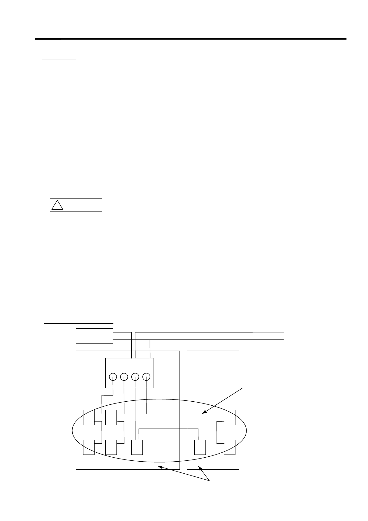
2. System Structure
Host
Remote I/O, DeviceNet, PROFIBUS-DP
Power source
Gateway (GW) Unit
24V DC
Communication line
+ Power supply line
A
B
A
B
A B
5m
A
5m
B
Tool
- 6 -
A : Manifold Valve / Relay Output
Module with the SI Unit
B : Input Unit / Input Block
Page 8
EX500 Serial System EX## - OME0008
3. Specification and Product numbers
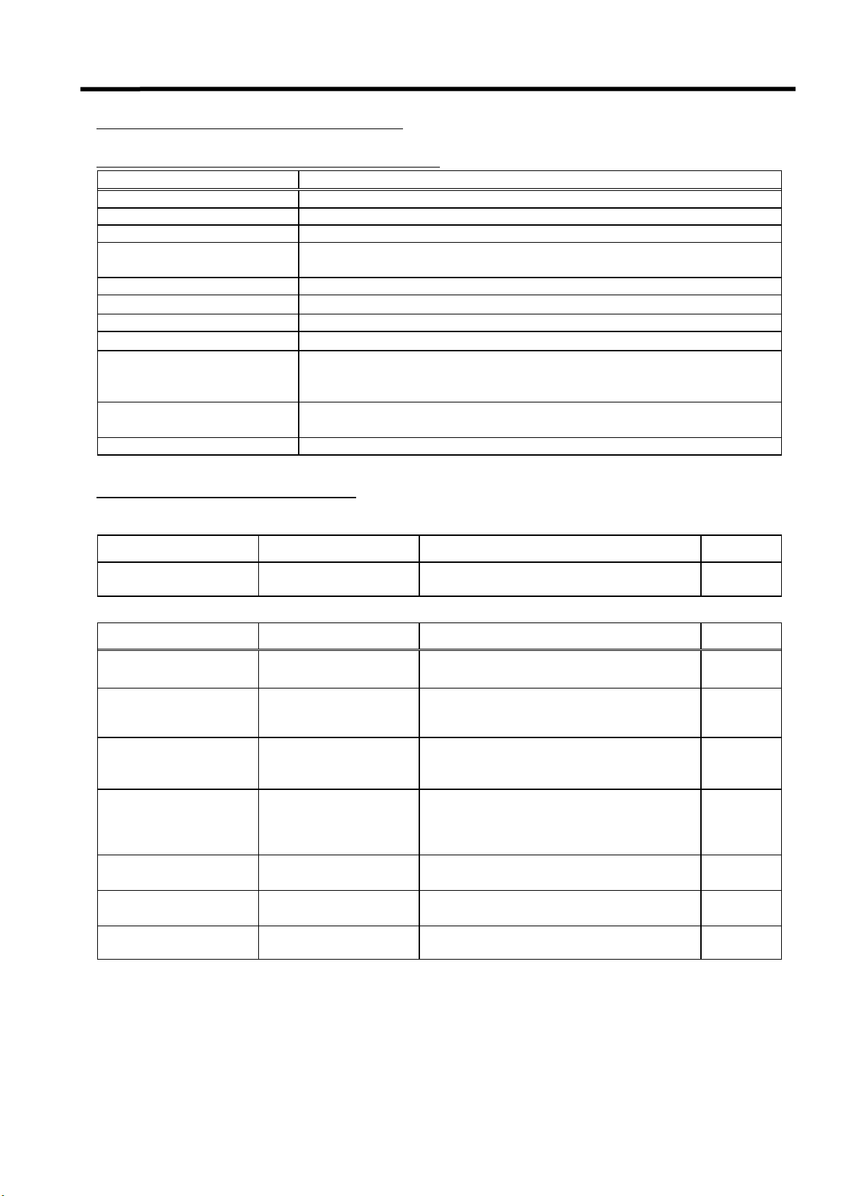
3 -1. General specification of EX500 series
Item Specification
Enclosure IP65
Standard UL,CSA,CE
Withstand voltage 1500V AC 1min. ( between PE - external terminal package )
Insulation resistance
Momentary power failure 1m sec. or less
Ambient temperature +5℃ to +45℃
Ambient humidity 35% to 85%RH ( without condensation )
Preservation temperature - 25℃ to 70℃
Vibration proof
Shock resistance
Applicable altitude Less than 1000m above sea
2MΩor more
( 500VDC meg. between PE - external terminal package )
10Hz to 57Hz 0.35mm ( constant amplitude )
57Hz to 150Hz 5G ( constant speed )
2 hours per each direction of ±X,Y and Z
Peak value : 15G
3 times per each direction of ±X,Y and Z
・・・・EMC Directive ( 89 / 336 / EEC )
EN50081-2 / 1993, EN55011 / 1998 +A1 : 1999, EN50082-2 / 1995, EN61000-6-2 / 1999
Electromagnetic Emission
Item Test Procedure Specification Criterion
Radiated Electric Field
Strength
Electromagnetic Susceptibility ( Immunity )
Item Test Procedure Specification Criterion
ESD
RS :
Radiated Susceptibility
( amplitude modulated)
RS :
Radiated Susceptibility
( pulse modulated )
CS :
Conductive
Susceptibility
( amplitude modulated)
EFT / Burst,
DC power lines
EFT / Burst,
control lines
Surge,
interface lines
EN55011 : 1998 +A1
: 1999
EN61000-4-2 : 1995 /
A1 : 1998
EN61000-4-3 : 1996 /
A1 : 1998
ENV50204 : 1995
EN61000-4-6 : 1996
EN61000-4-4 : 1995
EN61000-4-4 : 1995
EN61000-4-5 : 1995 ±1kV ( Common ) B
30MHz to 230MHz, 230MHz to 1GHz
( Distance : 10m )
±4kV contact
±8kV air discharge
80MHz to 1000MHz
10V / m ( 1kHz AM 80% )
900±5MHz
10V / m
( 200Hz Pulse Mod. Duty 50% )
0.15MHz to 80 MHz
10V ( 1kHz AM 80% )
±2kV
( 5 / 50ns, 5kHz )
±2kV
( 5 / 50ns, 5kHz )
Group 1
Class A
B
A
A
A
B
B
- 7 -
Page 9
EX500 Serial System EX## - OME0008
3 -2. Gateway ( GW ) Unit
How to Order
EX500-GDN1
Network communication
protocol
DN DeviceNet
PR PROFIBUS-DP PROFIBUS-DP
AB Remote I/O ( RIO ) -X1 Remote I/O ( RIO )
GW Unit compatible
DeviceNet
Nil
Gateway ( GW ) Unit
B
U
S
R
U
N
S
O
L
C
O
M
E
R
R
G
2
4
V
D
C
A
T
E
E
X
W
5
A
0
Y
0
U
S
N
E
I
T
R
I
E
S
S
S
S
S
M
M
M
M
C
C
C
C
S
E
R
I
A
L
I
P
N
O
C
M
.
A
O
D
D
I
E
E
N
P
I
U
N
T
/
V
J
O
O
A
I
U
L
P
P
T
T
6
A
P
A
5
N
U
G
T
E
6
2
4
E
4
/
V
X
6
D
4
C
5
/
0
2
0
0
0
m
-
A
G
A
C
B
O
M
1
-
D
X
C
T
Y
P
1
E
1
U
S
R
E
P
.
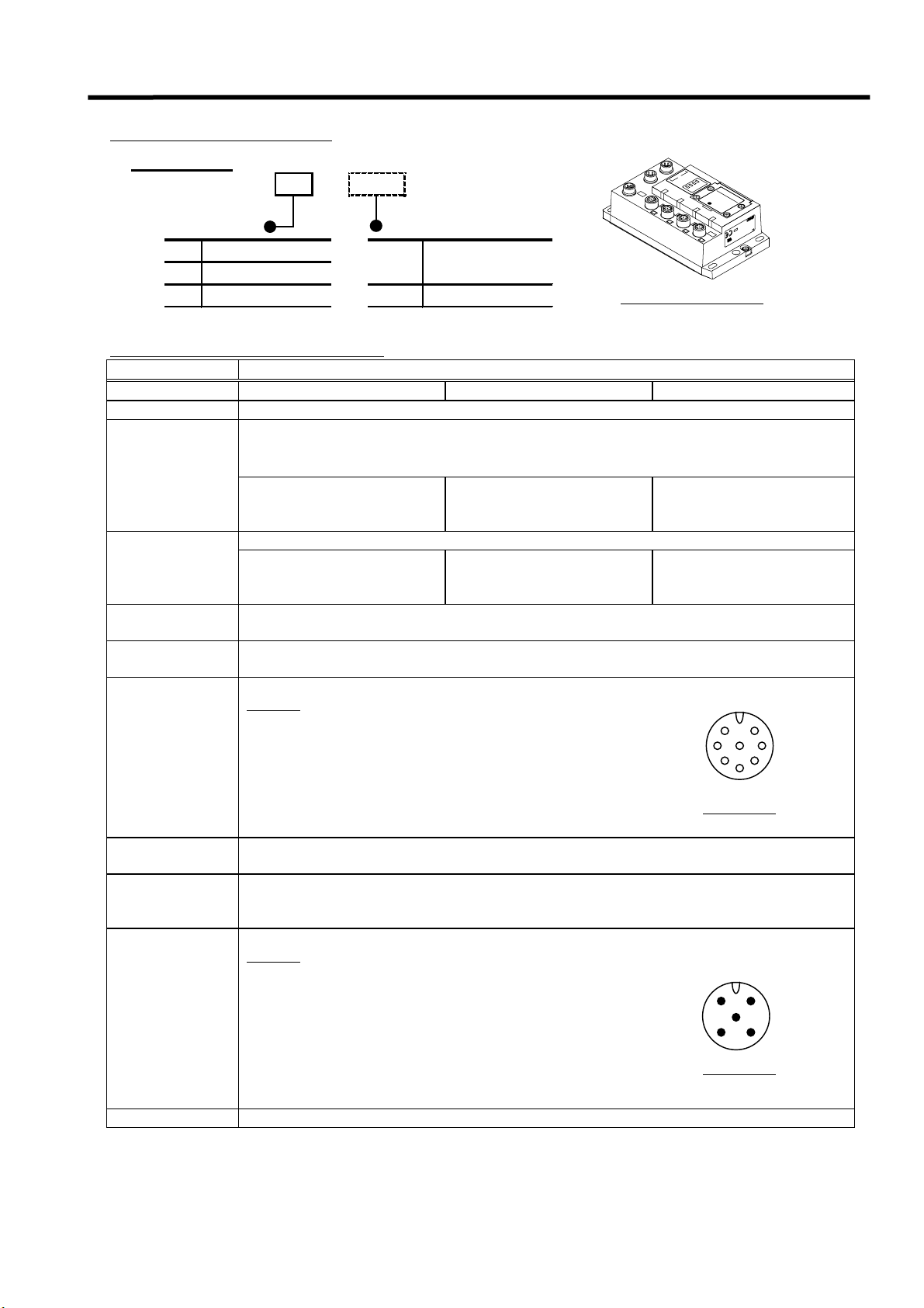
Gateway ( GW ) Unit specification
Item Specification
Models EX500 - GAB1 - X1 EX500 - GDN1 EX500 - GPR1
Rated voltage 24V DC
Input and control power supply : 24V DC ±10%
Solenoid valve power supply : 24V DC +10% / -5%
Power supply
voltage
Current
consumption
Input / Output
points
Input / Output
branches
Branch
connector
M12 connector ( 8 pin, socket )
Pin NO.
1. RD + 2. RD -
3. TD + 4. TD -
5. 24V DC ( for solenoid valve)
6. 0V DC ( for solenoid valve)
7. 24V DC ( for power source )
8. 0V DC ( for power source )
( Warning of voltage drop given lower than approx. 20V )
Communication power
-
supply for DeviceNet :
11V DC to 25V DC
200mA or less ( only GW Unit )
Communication power
-
supply for DeviceNet :
50mA or less
Maximum 64 inputs / Maximum 64 outputs
4 branches ( one branch 16 inputs / 16 outputs )
7
-
-
1
8
6
5
For GW Unit
2
3
Length of branch
cable
Communication
form
Less than 5m ( Less than 10m Max. Length )
Communication protocol : SMC original protocol
Communication speed : 750 k bit / sec. ( DeviceNet, PROFIBUS-DP )
: 500 k bit / sec. ( Remote I/O (RIO))
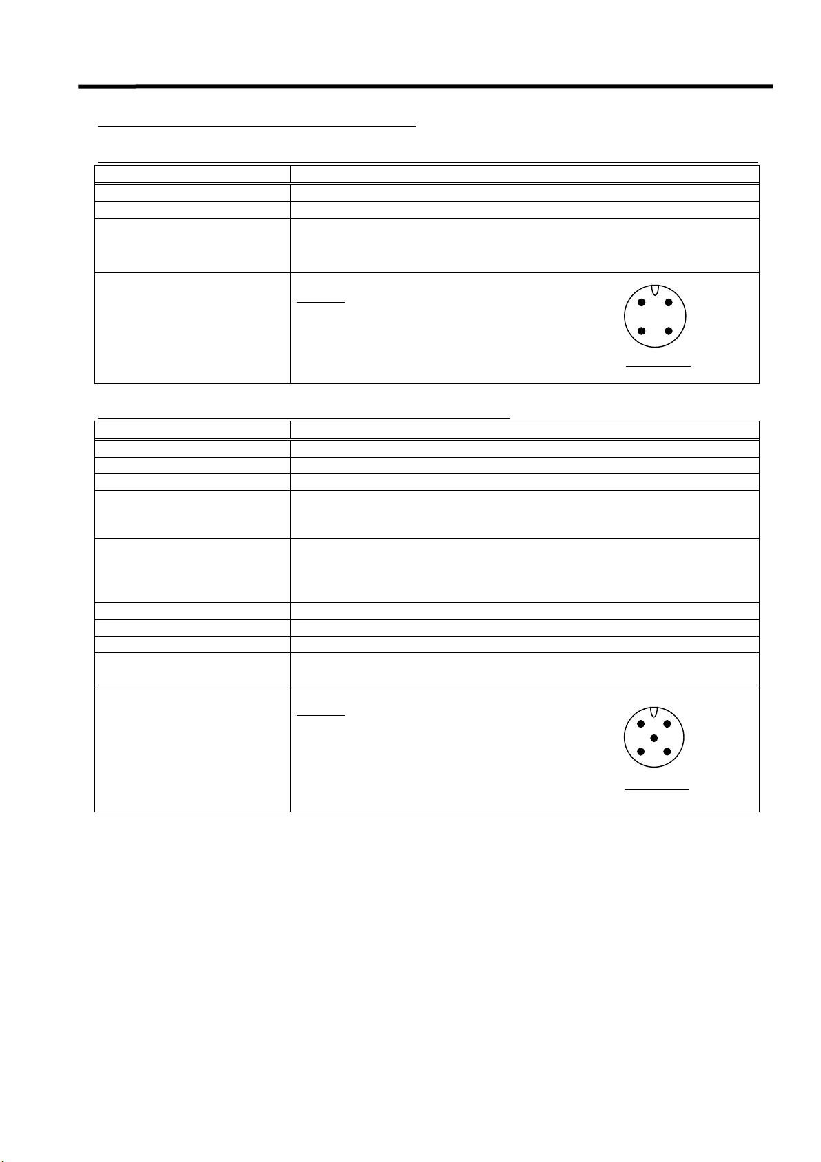
M12 connector ( 5 pin, plug )
Pin NO.
1. 0V ( for solenoid valve)
Power
Supply
connector
2. 24V DC + 10% / - 5% 3A Max.
( for solenoid valve)
3. 0V ( for power source ( input and control ) )
4. 24V DC±10% 3A Max.
( for power source ( input and control ) )
5. PE ( Protective earth )
Weight 470g
- 8 -
2
5
3
For GW Unit
1
4
Page 10
EX500 Serial System EX## - OME0008
・・・・Communication specification for each PLC
Rockwell Automation Remote I/O communication specification ( RIO ) ( EX500 - GAB1 - X1 )
Item Specification
Applicable PLC Rockwell Automation Remote I/O PLC
Communication speed 57.6 k bit / sec. , 115.2 k bit / sec. , 230.4 k bit / sec.
Cable distance
( Terminating resistor size )
57.6 k bit / sec. : 3048 m [ 10000 feet ] ( 150Ω)
115.2 k bit / sec. : 1524 m [ 5000 feet ] ( 150Ω)
230.4 k bit / sec. : 762 m [ 2500 feet ] ( 82Ω)
M12 connector ( 4 pin, plug )
Pin NO.
2
1
1. Line1 ( Blue )
Communication connector
2. N. C.
3. Line2 ( Clear )
4. Shield ( Shield )
3
For GW Unit
4
DeviceNet communication specification ( EX500 - GDN1 )
Item Specification
Communication protocol DeviceNet Release 2.0
Slave ( branch ) type Group2 Only Server
MAC ID setting range 0 to 63
Vender code : 7 ( SMC corp. )
Device information
Corresponding message
I/O message size Input : 8 byte , Output : 8 byte
Communication speed 125 k bit / sec. , 250 k bit / sec. , 500 k bit / sec.
Cable distance Refer to section 5 -1
Isolation
Communication connector
Product type : 12 ( Communication Adapter )
Product code : 5001
Duplicate MAC ID Check Message
Group2 Only Unconnected Explicit Message
Explicit Message
Poll I/O Message
Photo coupler
( between CAN transceiver - main circuit )
M12 connector ( 5 pin, plug )
Pin NO.
1. DRAIN
2. V+
3. V-
4. CAN_H
5. CAN_L
2
5
3
For GW Unit
1
4
- 9 -
Page 11
EX500 Serial System EX## - OME0008
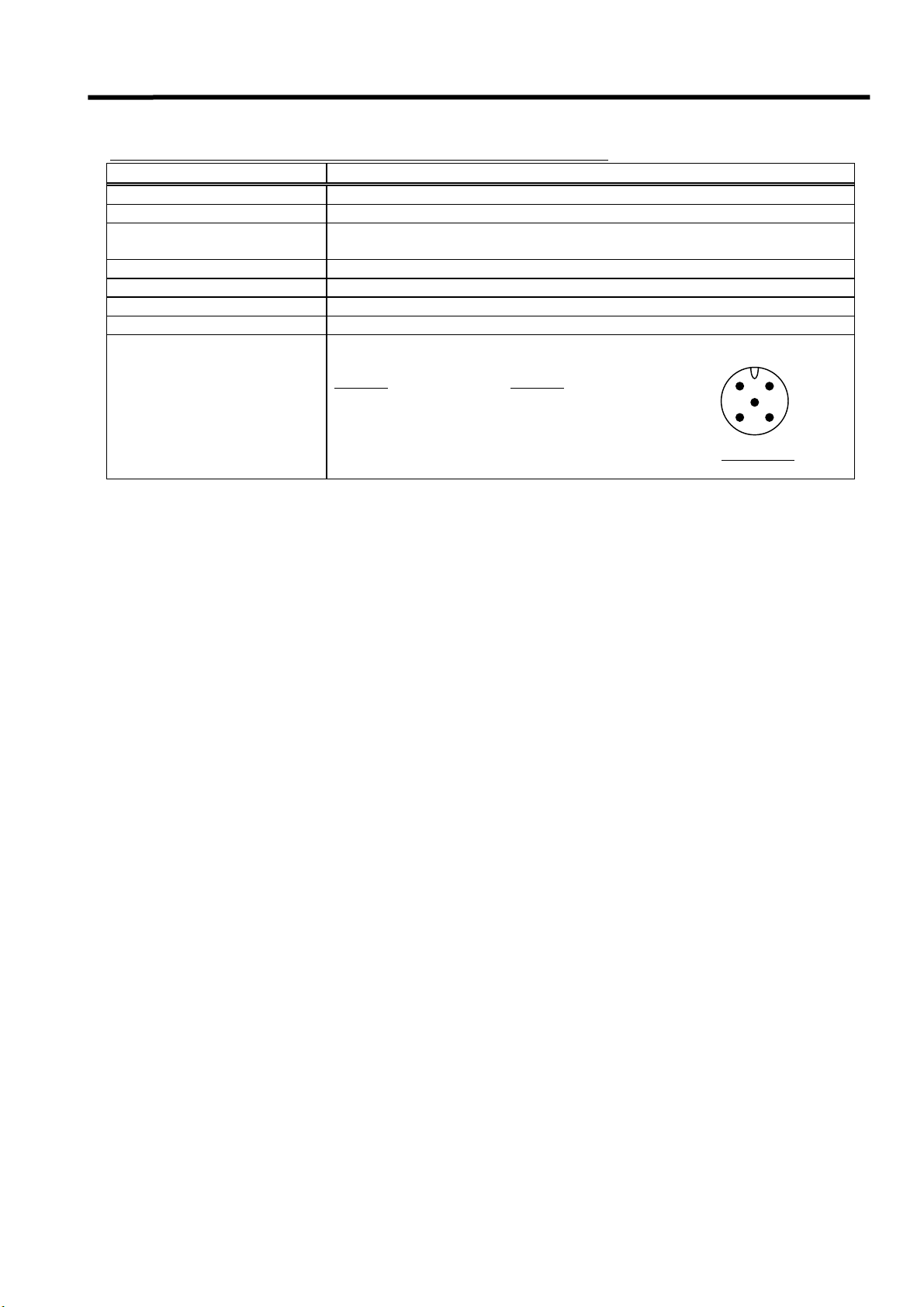
PROFIBUS-DP communication specification ( EX500 - GPR1 )
Item Specification
Protocol PROFIBUS-DP ( EN50170 )
Bus interface EIA RS - 485
Communication speed
Cable distance Refer to section 6 -1
Freeze function Available
Synchronous function Available
ID number 1405 hex
Communication connector
9.6 / 19.2 / 93.75 / 187.5 / 500 k bit / sec.
1.5 / 3 / 6 / 12 M bit / sec.
M12 connector ( 5 pin, plug )
IN
Pin NO.
1. VP
2. RxD / TxD ( N )
3. DGND
4. RxD / TxD ( P )
5. Shield
OUT
Pin NO.
1. N.C.
2. RxD / TxD ( N )
3. N.C.
4. RxD / TxD ( P )
5. Shield
2
5
3
For GW Unit
1
4
- 10 -
Page 12
EX500 Serial System EX## - OME0008
3 -3. Input Unit Manifold
The Input Unit Manifold can have various combinations depending on the number of stations and type of
the sensor connector.
When placing an order, the input manifold part number and the input block part number are entered together.
But only one sensor type has to be specified per manifold ( either NPN or PNP ).
M8 Input Block M12 Input Block M8 and M12 mixed
3 -3 -1. Input Manifold
The Input Manifold includes Input Unit ( EX500 - IB1 ( -X1 ) ), End Block and DIN rail.
How to Order
EEX5 0 0 - I B1-E8
E
X
V
Input Unit Specification
Connector type
E M8 connector
T M12 connector
M M8, M12 mixed Stations
1
:
8
GW Unit compatible
DeviceNet
Nil
PROFIBUS-DP
-X1 Remote I/O ( RIO )
1 station
:
8 stations
5
O
0
L
T
0
A
I
-
G
N
I
E
P
U
B
I
2
T
P
1
4
V
C
D
S
O
C
E
D
/
R
E
6
I
5
A
0
L
m
N
A
o
.
1
6
I
P
6
5
C
M
A
D
E
I
T
N
J
A
P
A
N
R
Y
U
P
S
E
1
Input Manifold
3 -3 -2. Input Unit
How to Order
EX500- IB1
GW Unit compatible
DeviceNet
Nil
PROFIBUS-DP
-X1 Remote I/O ( RIO )
Input Unit specification
Item Specification
Current source type Input Block ( PNP )
Connecting block
Current sink type input Block ( NPN )
Number of connecting block 8 blocks Max.
Power supply for block 24V DC
Current supply for block 0.65A Max.
Current consumption 100mA or less ( in case of rated voltage )
Short circuit protection
1A Typ. for each unit ( supply power cut )
Cut the power for power source once and then supply it again for return.
M12 connector ( 8 pin, plug )
Pin NO.
1. RD + 2. RD -
Communication connector
3. N. C. 4. N. C.
5. N. C. 6. N. C.
7. 24V DC ( for power source )
8. 0V DC ( for power source )
Weight 100g ( Input Unit + End Block )
or
E
X
V
5
O
0
L
T
0
A
I
-
N
G
I
E
P
U
B
I
2
T
P
1
4
V
C
D
S
O
C
E
D
/
R
E
6
I
5
A
0
L
m
N
A
o
.
1
6
I
P
6
5
M
A
D
E
I
N
J
A
Input Unit
C
R
T
Y
U
S
P
E
1
P
A
N
2
3
1
8
7
6
5
For Input Unit
- 11 -
Page 13

EX500 Serial System EX## - OME0008
3 -3 -3. Input Block
How to Order
EX5 00 - I E1
E
X
5
0
0
I
E
1
2
4
(
V
D
P
C
N
/
6
P
C
0
)
m
R
A
/
I
P
6
5
U
S
T
Y
P
E
1
M
A
D
E
I
Connector type GW Unit compatible
Input specification
1 M8 connector, PNP
2 M8 connector, NPN
DeviceNet
Nil
PROFIBUS-DP
-X1 Remote I/O ( RIO )
3 M12 connector, PNP
4 M12 connector, NPN
5 8 point unit, M8 connector, PNP
6 8 point unit, M8 connector, NPN
N
J
A
P
A
N
M8 Input Block
E
X
V
5
O
0
L
T
0
A
-
G
I
E
I
P
E
2
C
4
5
O
V
S
D
D
E
E
(
C
R
/
P
I
2
N
A
4
L
0
P
N
m
o
)
A
.
I
P
6
C
5
M
R
A
D
E
I
T
N
Y
U
S
P
J
E
A
P
1
A
N
E
X
5
0
0
V
-
O
L
I
T
E
A
G
3
I
E
(
P
P
C
O
N
D
P
E
2
)
4
V
D
C
/
6
C
0
R
m
A
T
I
P
Y
U
6
P
S
5
E
1
M
A
D
E
I
N
J
A
P
A
N
M12 Input Block
Input Block specification
8 point unit Input Block ( M8 )
Item Specification
Corresponding sensor Current source type ( PNP output ) Current sink type ( NPN output )
M8 connector ( 3 pin, socket )
Pin NO.
1. power supply (24V DC )
3. power supply ( 0V )
4. input
Sensor connector
For Input Block
M12 connector ( 4 pin, socket )
Pin NO.
1. power supply (24V DC )
2. ( input ) *Note
3. power supply ( 0V )
4. input
1
4
For Input Block
Input points 2 points / 8 points ( M8 only )
Rated voltage 24V DC
Logical ” 1 ” input voltage
Logical ” 0 ” input voltage
Logical ” 1 ” input current
Logical ” 0 ” allowable current
15V to 26.4V 0V to 8V
0V to 5V 19V to 26.4V
5mA Typ. - 5mA Typ.
1.5mA - 1.5mA
Input delay 1m sec. or less
Display LED ( green - colored ) light up
Insulation Nothing
Sensor supply current 30mA Max. / sensor
Weight [ M8 : 20g ] [ M12 : 40g ] [ 8 points ( M8) : 55g ]
2
3
Note) Internal circuit of the M12 Input Block and the position of the key for installing the sensor
connector of the M12 Input Block.
Each No.2 pin of each sensor connector of the M12 Input
Block is connected to the next No.4 pin which is the sensor
signal input pin of the connector.
Therefore, it is possible to incorporate the two input signals
of the sensor into one cable. ( just like a Y connection )
Input “0” ( n ) side
0
3
4
1
2
Key
Input “1” ( n + 1 ) side
Key
2
1
4
Confirm the specification of the output signal when
connecting the sensor. It will cause the malfunction.
The position of the key for installing the sensor connector
Input “1” ( n + 1 )
Input “0” ( n )
of the M12 Input Block refers to the right figure.
Confirm the type of the sensor connector when
selecting a sensor.
Figure of M12 Input Block ( the top of view )
- 12 -
1
3
Page 14

EX500 Serial System EX## - OME0008
3 -4. SI Unit
SI Unit for SV series Manifold Valve SI Unit for VQC series Manifold Valve
How to Order
EX500-S001
How to Order
EX500-Q101
GW Unit compatible
DeviceNet
Nil
PROFIBUS-DP
-X1 Remote I/O ( RIO )
Output specification
0 NPN output ( + COM. )
1 PNP output ( - COM. )
GW Unit compatible
DeviceNet
Nil
PROFIBUS-DP
-X1 Remote I/O ( RIO )
SI Unit specification
Item Specification
Models EX500 - S001 ( -X1 ) EX500 - Q□01 ( -X1 )
Connecting
block
Number
of
connecting block
Power supply for block
Current supply for block
Current consumption
Short circuit
protection
Communication
connector
Weight 115g 105g
Solenoid valve ( Single , Double )
Relay Output Module ( 1 output , 2 output )
Double solenoid valve , : 8 blocks Max.
Relay Output Module ( 2 output )
Single solenoid valve , : 16 blocks Max.
Relay Output Module ( 1 output )
Solenoid valve ( Single , Double )
Double solenoid valve : 8 blocks Max.
Single solenoid valve : 16 blocks Max.
24V DC
0.65A Max. 0.75A Max.
100mA or less ( in case of rated voltage )
Use current limit driver
Once the driver circuit is shorted, current is limited in order to de-energize the load.
Once the short circuit is fixed, the unit will self recover.
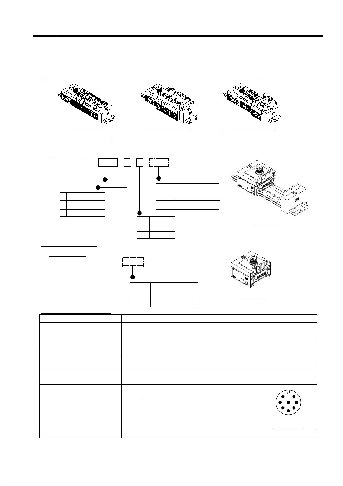
Connecting with Input Unit. M12 connector ( 8 pin, socket )
C1
Pin NO.
1. RD + 2. RD -
or
3. N. C. 4. N. C.
5. N. C. 6. N. C.
“ 0 “
7. 24V DC ( for power source )
8. 0V DC ( for power source )
Connecting with GW Unit. M12 connector ( 8 pin, plug )
C2
or
“ 1“
Pin NO.
1. RD + 2. RD -
3. TD + 4. TD -
5. 24V DC ( for solenoid valve)
6. 0V DC ( for solenoid valve)
7. 24V DC ( for power source )
8. 0V DC ( for power source )
1
7
6
For SI Unit
2
3
For SI Unit
2
8
3
5
1
8
7
6
5
3 -5. Applicable Manifold Valve series
Series
SV1000
SV2000
SV3000 -
SV4000 VQC1000 VQC2000 VQC4000 -
Refer to the Catalogues or Technical Instruction Manual of SV and VQC series Manifold Valve
for more details.
Manifold Applicable cylinder size ( mm )
Cassette
type
○○○○○
○○○○○
Tie-rod
type
○
○○
○
○○
40 50 63 80 100 125
○○○○
○○○○
○○○○
○○○○
○○○○
- 13 -
Page 15

EX500 Serial System EX## - OME0008
L
3 -6. Option
3 -6 -1. Communication Connector / Cable
1. Communication Connector for Remote I/O ( RIO ) ( EX500 - GAB1 -X1 )
How to Order
EX500 -AC000-AB
1
×
2
1
M
2
1
3
4
φ14.9
43.2
Applicable cable diameter
φ6 (φ5~φ6 )
Rated voltage 125V DC
Rated current 3A
Contact
resistance
( connector part )
φ14.2
.
Insulation
resistance
Withstand
voltage
( connector part )
Electric specification
40m ohms or less
( At 20mV DC or less, 100mA or less )
1000M ohms or more ( At 500V DC )
1500V AC 1min.
( Leak current 1mA or less )
2. Communication Connector Cable for DeviceNet ( EX500 - GDN1 )
How to Order
EX500 -AC050-DN
Rated voltage 125V DC
Electric specification
Rated current 3A
Contact
resistance
( connector part )
Insulation
resistance
Withstand
voltage
( connector part )
40m ohms or less
( At 20mV DC or less, 100mA or less )
1000M ohms or more ( At 500V DC )
1500V AC 1min.
( Leak current 1mA or less )
M12
L : Cable length
010 1m
050 5m
φ7
1
5
2
43
Socket connector
Pin assignment
Outside
diameter
Sheath color
φ14.9
40.7
L
Cable specification
Signal AWG24 ( 41 / 0.08 )
Power supply AWG22 ( 19 / 0.16 )
Drain AWG22 ( 19 / 0.16 ) -
Φ7
Light blue
- 14 -
50
Terminal NO.
1
2
3
4
5
Blue /
White
Red /
Black
Cable core
sheth color
: DRAIN
Red : V+
Black : V-
White : CAN H
Blue : CAN
Wiring
Terminal NO. Cable color / Signal name
1
2
3
4
5
Bare
Red
Black
White
Blue
DRAIN
V+
V-
CAN H
CAN L
Page 16

EX500 Serial System EX## - OME0008
3 -6 -2. Branch Cable with M12 Connector
How to Order
EX500-AC030-SSPS
L : Cable length Connector specification
003 0.3m
005 0.5m
010 1m
030 3m
050 5m
Electric specification
Rated voltage 36V DC
Rated current 1.5A
Contact
resistance
( connector part )
Insulation
resistance
Withstand
voltage
( connector part )
40m ohms or less
( At 20mV DC or less, 100mA or less )
1000M ohms or more ( At 500V DC )
1000V AC 1min.
( Leak current 1mA or less )
SSPS
SAPA
Socket side : Straight, Plug side : Straight
Socket side : Angled, Plug side : Angled
M12
M12
28.3
L
48
φ6
φ14.9
52
φ16
M12
Straight connector type
M12
φ6
32.3
31.3 31.3
L
Angled connector type
8
7
6
Socket connector Plug connector
2
1
3
4
5
Terminal NO.
11
22
33
44
55
66
77
88
Cable core
sheath color
White
Brown
Green
Yellow
Gray
Pink
Blue
Shield
8
1
2
3
4
5
Pin assignmentPin assignment
Wiring
- 15 -
7
6
Page 17

EX500 Serial System EX## - OME0008
A
W
3 -6 -3. Power Supply Connector Cable
How to Order
EX5 00 -AP050-S
L : Cable length
010 1m
050 5m
Connector
spesification
Straight
S
Angled
A
Rated voltage 125V DC
Rated current 3A
Contact
resistance
( connector part )
Insulation
resistance
Withstand
voltage
( connector part )
Electric specification
40m ohms or less
( At 20mV DC or less, 100mA or less )
1000M ohms or more ( At 500V DC )
1500V AC 1min.
( Leak current 1mA or less )
M12
φ6
28.3
31.3
M12
φ6
18
φ14.9
34
48
L
30 5
50
Straight connector type Angled connector type
Teminal NO.
1
5
43
Socket connector
Pin assignment
2
1
2
3
4
5
3 -6 -4. Terminal Plug
Wiring
Cable core
sheath color
Brown : 0V ( for solenoid valve )
White : 24V DC +10% / -5% ( for solenoid valve )
Blue : 0V ( for power source )
Black : 24V DC
Gray : PE
±
10% ( for power source )
Terminal NO. Cable color / Signal name
1 Brown 0V ( for solenoid valve)
2 White 24V DC +10% / -5%
3 Blue 0V ( for power source)
4Black
5Gray PE
When Input Unit Manifold is not required, a Terminal Plug should be hooked up with port C1 ( for SV Valve
Manifold ) or port 0 ( for VQC Valve Manifold ).
Without this plug, the communication LED of GW Unit will not light up.
How to Order
EX500 -AC000 - S
M12
8
2
1
3
4
5
Plug connector
Pin assignment
7
φ16
6
44.7
Rated voltage 36V DC
Rated current 1.5A
Contact
resistance
( connector part )
Insulation
resistance
Withstand
voltage
( connector part )
Electric specification
40m ohms or less
( At 20mV DC or less, 100mA or less )
1000M ohms or more ( At 500V DC )
1000V AC 1min.
( Leak current 1mA or less )
30 5
50L
( for solenoid valve)
24V DC ±10%
( for power source)
3 -6 -5. Water Proof Cap
To accommodate the product’s water proof feature, a Water Proof Cap is used for an open port in the GW Unit
and the Input Block. The Cap is supplied with the product when ordered.
Tighten the Water Proof Cap with the specified tightening torque. ( M8 : 0.05 N・
How to Order
EX500 -
Connector
specification
ES
M8 connector ( socket ) / 10 pcs.
TP
M12 connector ( plug ) / 1 pc.
TS
M12 connector ( socket ) / 10 pcs.
- 16 -
・m, M12 : 0.1 N・・・・m )
・・
Page 18

EX500 Serial System EX## - OME0008
4. How to operate EX500 - GAB1 - X1 ( Rockwell Automation Remote I/O ( RIO))
4 -1. Applicable PLC
Applicable PLCs in which Rockwell Automation Remote I/O ( RIO ) system is installed.
Please contact Rockwell Automation for more details.
・
・Representative PLC
・・
SLC500
PLC - 2 / 20 PLC - 2 / 30 PLC - 3 / 10
PLC - 5 / 11 PLC - 5 / 15 PLC - 5 / 20 PLC - 5 / 25
PLC - 5 / 30 PLC - 5 / 40 PLC - 5 / 40L PLC - 5 / 60
PLC - 5 / 60L PLC - 5 / 80
PLC - 5 / 250 PLC - 5 / VME PLC - 5 / V40B
4 -2. Parts description
Fieldbus connector
(1771 Remote I/O)
Power supply connector
Communication port A
Communication port B
Communication port C
Communication port D
B
U
S
R
U
N
S
O
L
C
O
M
E
R
2
4
V
D
C
R
LED display window
G
A
T
E
E
W
X
A
5
Y
0
0
U
N
S
I
E
T
R
I
E
S
S
S
S
S
M
M
M
M
C
C
C
C
J
A
P
A
N
C
O
M
D
C
X
T
Y
P
E
1
1
U
S
R
Station switch protection cover
S
E
R
I
A
L
I
P
N
O
C
M
.
O
A
D
D
I
E
N
E
P
U
I
T
N
/
V
O
O
I
U
L
P
T
T
6
P
A
5
U
G
T
E
6
2
E
4
4
/
V
X
6
D
4
C
5
/
0
2
0
0
0
m
-
A
G
A
B
1
-
E
P
a. Fieldbus connector : Port for PLC connection.
b. Power supply connector : The power source for Input Unit, SI Unit, and control and
for the solenoid valve is connected through this port.
c. Communication port : Input Unit Manifold or the Manifold Valve with the SI Unit
is connected through this port.
d. LED display window : The state of the power source supply and the PLC
communication is displayed. ( Refer to section 4 -3 )
e. Station switch protection cover : Switches for the operation setting are inside.
( Refer to section 4 -4 )
!!!! CAUTION
The station switch protection cover should be tightened with specified tightening torque
after it is opened. ( Tightening torque : 0.6 N・m )
- 17 -
Page 19

EX500 Serial System EX## - OME0008
4 -3. LED display
GATEWAY UNIT
RUN
BUS
SOL
COM
ERR
COM A COM B COM C COM D
Display Content
RUN
SOL
COM
ERR
COM A
COM B
COM C
COM D
Source ON : Lights
Source OFF : Lights off
Solenoid valve source voltage is normal :Lights
Voltage lowered to 20V or less :Lights off
RIO communication is normal : Lights
RIO communication is abnormal : Lights off
RIO communication is abnormal : Lights
RIO communication is normal : Lights off
Communication port A is receiving data : Lights
Communication port A has no data : Lights off
Communication port B is receiving data : Lights
Communication port B has no data : Lights off
Communication port C is receiving data : Lights
Communication port C has no data : Lights off
Communication port D is receiving data : Lights
Communication port D has no data : Lights off
EX500 SERIES
!!!! CAUTION
When the Input Unit Manifold is not connected, the respective COM LED of the GW Unit will not light up.
To monitor the status of COM port, it is necessary to use a Terminal Plug.
The COM LED will light up when a Terminal Plug is used. ( Refer to section 3 -6 -4 )
4 -4. Operation setting
Turn the power supply OFF when setting switches.
Open the station switch protection cover and set the dip switch with a flat blade screw driver.
ON
12345678
SW1 SW2 SW3
ON
1234
- 18 -
Page 20

EX500 Serial System EX## - OME0008
)
A
)
O
4 -4 -1. Operation setting switch ( SW1 )
This switch sets RACK Address / Starting Quarter.
( 1 ) RACK Address ( 6 bit setting )
0 to 74 ( OCT : octal number ) 61 types
of setting are available.
SW1
( 2 ) Starting Quarter ( 2 bit setting )
Three types of setting
( First, Second, Third )
are available.
4 -4 -2. Operation setting switch ( SW2 )
( 1 ) Last RACK ( 1 bit setting )
With Last RACK, the switch is set as “ 1 ” ( ON ).
RACK
ON ( 1 )
OFF ( 0 )
SW1 NO.
RACK 2000010
Address |
Starting Second 0 1
Quarter Third 1 0
N
12345678
32 16 8 4 2 1
0000000
1000001
73111011
74111100
Last RACK ( 1bit ) Mode ( 1bit
ddress ( 6bit
EX.)
111100b→74o
First 0 0
Fourth - -
Data Rate
( 2bit )
Starting Quarter ( 2bit )
01→ Second
( 2 ) Data Rate ( 2 bit setting )
Set data communication rate.
57.6 k bit / sec. : 00
115.2 k bit / sec. : 01
230.4 k bit / sec. : 1X
Data Rate 57.6 k bit / sec. 0 0
( 3 ) Mode ( 1 bit setting )
Setting Operation
0
Clear
1
Hold
If “ 0 ” ( OFF ) set , output status is cleared and held temporarily when Remote I/O ( RIO )
has communication error.
When returned to normal signal, the communication will automatically be recovered.
If “ 1 ” ( ON ) set , operation held temporarily holding the last normal output signal when
Remote I/O ( RIO ) has communication error.
When returned to normal signal, the communication will automatically be recovered.
ON ( 1 )
SW2
OFF ( 0 )
SW2 NO. 1234
Last
RACK
Mode Clear 0
ON
1234
NO 0
YES 1
115.2 k bit / sec. 0 1
230.4 k bit / sec. 1 X
Hold 1
- 19 -
Page 21

EX500 Serial System EX## - OME0008
4 -4 -3. Terminating resistance setting switch ( SW3 )
Set termination resistance.
①150Ω ②82Ω ③No resistance
Data Rate
57.6 k bit / sec. : 150Ω
115.2 k bit / sec. : 150Ω
230.4 k bit / sec. : 82Ω
State of SW3
4 -5. Layout of scanner I/O
I/O mapping image at the Gateway (GW ) Unit communication port is shown in examples 1 and 2.
In this product, regardless of the quantity of the I/O equipment, continuous 4 Groups are automatically
occupied. ( 1/2 RACK occupation ).
Each communication port occupies all of 16 points in corresponding Group.
Ex.1 ) RACK Address = 0
Starting Quarter = First
Bit Number( decimal ) 15 14 13 12 11 10 9 8 7 6 5 4 3 2 1 0
RACK0 Group0
RIO RACK0 Group1
LOGICAL RACK0 Group2
RACK0 RACK0 Group3
RACK0 Group4
RACK0 Group5
RACK0 Group6
RACK0 Group7
RACK1 Group0
RIO RACK1 Group1
LOGICAL RACK1 Group2
RACK1 RACK1 Group3
RACK1 Group4
RACK1 Group5
RACK1 Group6
RACK1 Group7
COM A occupied
COM B occupied
COM C occupied
COM D occupied
Ex.2 ) RACK Address = 1
Starting Quarter = Third
Bit Number( decimal ) 15 14 13 12 11 10 9 8 7 6 5 4 3 2 1 0
RACK0 Group0
RIO RACK0 Group1
LOGICAL RACK0 Group2
RACK0 RACK0 Group3
RACK0 Group4
RACK0 Group5
RACK0 Group6
RACK0 Group7
RACK1 Group0
RIO RACK1 Group1
LOGICAL RACK1 Group2
RACK1 RACK1 Group3
RACK1 Group4
RACK1 Group5
RACK1 Group6
RACK1 Group7
- 20 -
COM A occupied
COM B occupied
COM C occupied
COM D occupied
Page 22

EX500 Serial System EX## - OME0008
5. How to operate EX500 - GDN1 ( DeviceNet )
5 -1. Connection style
DeviceNet unit can be connected by T branch, Multi branch and Branch line branch.
Total extension length of trunk and stay is different depending on communication speed and thickness of
communication cable.
EX500 series can be connected only by T branch.
Terminating resistance
Multi branch
Branch line
Node Node
・・・・Wiring length
of
Network
Total length of branch line
Terminating resistance 121 ohms, 1/2W ( TURCK p / n = RSM57TR2 )
Multi branch
T branch
Node Node
Max. 6m
Branch line
Node
Node
Branch line
125 250 500
Communication speed ( k bit / sec. )
Thick cable 500m or less 250m or less 100m or less Max. length
Thin cable 100m or less
156m or less 78m or less 39m or less
Note : Max. length of a branch line is up to 6m.
Main
Multi
Terminating resistance
Branch line branch
Node
Node
Node
・
・Cable specification
・・
Item
Conductor
section area
Color
Signal Power Signal Power
0.82mm
Blue ( CAN-L )
White ( CAN-H )
Thick cable Thin cable
2
1.65mm
Red ( 24VDC ),
Black ( 0VDC )
2
0.20mm
2
Blue, W hite Red, Black
Impedance 120 ohms±10% - 120 ohms±10% -
Propagation
delay
1.36ns / ft - 1.36ns / ft -
( Maximum )
Attenuation
rate
( Maximum )
500kHz : 0.25dB / ft 500kHz : 0.50dB / ft
125kHz : 0.13dB / ft 125kHz : 0.29dB / ft
1.00MHz : 0.40dB / ft
-
1.00MHz : 0.70dB / ft
Conductor
resistance
6.9 ohms / 1000ft 3.6 ohms / 1000ft 28 ohms / 1000ft 17.5 ohms / 1000ft
( Maximum )
1ft ≒ 0.3048m
0.33mm
-
2
- 21 -
Page 23

EX500 Serial System EX## - OME0008
5 -2. Parts description
Fieldbus connector
(DeviceNet)
Power supply connector
B
U
S
D
e
V
2
4
V
D
C
M
S
N
S
S
i
O
c
L
e
N
C
O
N
F
O
e
R
M
A
N
C
t
E
T
E
S
T
T
M
E
D
C
Communication port A
Communication port B
Communication port C
Communication port D
a. Fieldbus connector : Port for PLC connection.
b. Power supply connector : The power source for Input Unit, SI Unit, and control and
for the solenoid valve is connected through this port.
c. Communication port : Input Unit Manifold or the Manifold Valve with
the SI Unit is connected through this port.
d. LED display window : The status of power source supply and the PLC
communication is displayed here. ( Refer to section 5 -3 )
e. Station switch protection cover : Rotary switches for the operation setting are inside.
( Refer to section 5 -4 )
LED display window
G
A
T
E
E
W
X
A
5
Y
0
0
U
N
S
I
E
T
R
I
E
S
S
S
S
S
M
M
M
M
C
C
C
C
I
N
J
A
P
A
N
6
4
0
m
O
M
D
A
1
T
Y
P
E
C
1
U
S
R
Station switch protection cover
S
E
R
I
A
I
L
P
N
C
M
O
O
A
I
.
D
D
N
E
E
P
U
T
V
/
O
O
L
U
I
T
T
P
A
P
6
G
U
E
5
T
E
2
6
X
4
4
V
5
/
D
0
C
/
0
2
-
0
G
D
N
E
P
!!!! CAUTION
The station switch protection cover should be tightened with specified tightening torque
after it is opened. ( Tightening torque : 0.6 N・m )
- 22 -
Page 24

EX500 Serial System EX## - OME0008
5 -3. LED display
GATEWAY UNIT
BUS
MS
NS
SOL
COM A COM B COM C COM D
Display Content
MS
Operating in a normal condition : Green lights
Recoverable fault ( Memory is abnormal ) : Red lights
Not online : Lights off
Online , Not Allocated : Green flashing
NS
Online , Allocated : Green lights
Connection Time - Out : Red flashing
Critical Link Failure : Red lights
SOL
COM A
COM B
COM C
COM D
Solenoid valve source voltage is normal : Lights
Voltage lowered to 20V or less : Lights off
Communication port A is receiving data : Lights
Communication port A has no data : Lights off
Communication port B is receiving data : Lights
Communication port B has no data : Lights off
Communication port C is receiving data : Lights
Communication port C has no data : Lights off
Communication port D is receiving data : Lights
Communication port D has no data : Lights off
EX500 SERIES
!!!! CAUTION
When the Input Unit Manifold is not connected, the respective COM LED of the GW Unit will not light up.
To monitor the status of COM port, it is necessary to use a Terminal Plug.
The COM LED will light up when a Terminal Plug is used. ( Refer to section 3 -6 -4 )
5 -4. Operation setting
Turn the power supply OFF when setting switches.
Open the station switch protection cover and set the rotary switch with a flat blade screw driver.
0
1
2
3
4
5
SW1 SW3SW2
9
8
7
6
Figure of setting switch
- 23 -
Page 25

EX500 Serial System EX## - OME0008
5 -4 -1. Address setting switch ( SW1, 2 )
These switches set node address. The setting is shown in Table 1.
5 -4 -2. Data rate setting switch ( SW3 )
This switch set data rate. The setting is shown in Table 2.
The factory default address and data rate are 63 and 125 k bit / sec. respectively.
X10 X1
SW1
SW1 SW2 NODE ADDRESS
00 0
01 1
02 2
||
63 63
64
|PGM
99
SW2
Table 1 Table 2
SW3
SW3 DATA RATE
0 125 k bit / sec.
1 250 k bit / sec.
2 500 k bit / sec.
3
|PGM
9
When PGM mode is chosen, the address
and data rate are set through network.
5 -5. I/O memory map
The GW Unit can control 128 input / output points in total. Regardless of I/O points of the equipment,
it always occupies each data memory area for 64 inputs and 64 outputs.
Once the address is assigned in the GW Unit, every port then corresponds to a specific “Word” respectively.
So “Word (n)” always corresponds to COM A, “Word (n+1)” corresponds to COM B, and so on.
Ex.) n = 1
In case of the input data, the sensor signal data of the Input Manifold which was connected with
the COM A port, occupies "Word1" of the I/O memory mapping.
If a sensor signal is stored in the "0 bit" of the Input Manifold, it becomes like the Figure below.
In the same way, in the case of the output data, the contents displayed in "Word1" of the
I/O memory mapping is output by the COM A port.
( m,n=0 - )
Word ( n ) COM A 1
Word ( n+1 ) COM B
Word ( n+2 ) COM C
Word ( n+3 ) COM D
:
:
Branch
connector
:
:
MSB LSB MSB LSB
15 8 7 0
Byte (m+1) Byte (m)
Byte (m+3) Byte (m+2)
Byte (m+5) Byte (m+4)
Byte (m+7) Byte (m+6)
Data ( 2 byte )
!!!! CAUTION
Read carefully the user manual of PLC which is used as a master.
The method of PLC setup, reading from or writing to memory differ from one PLC manufacturer to another.
- 24 -
Page 26

EX500 Serial System EX## - OME0008
6. How to operate EX500 - GPR1 ( PROFIBUS-DP )
6 -1. Communication wiring
・・・・Cable specification
A twisted pair cable with shield is used in the
communication wiring of PROFIBUS- DP.
A maximum length of cable depend on
communication speed.
The specification of cable length is based on
TYPE A cable which has parameters shown below.
・
・Communication speed and Longest wiring length
・・
Communication
speed
Wiring
length
9.6
[k bit/sec]
19.2
[k bit/sec]
1200
[m]
93.75
[k bit/sec]
[k bit/sec]
・・・・Terminating resistance
It is necessary to attach terminating
resistance to the units located at the
Data Line
ends of transmission line.
Refer to section 6 -4 -2, for setting
the terminating resistance.
Data Line
6 -2. Parts description
Fieldbus connector
(PROFIBUS-DP)
Impedance 135 ohms to 165 ohms
Capacitance between
conductors
30 pF / m or less
Conductor resistance 110 ohms / km
Cable diameter 0.64 mm
Conductor area 0.34 mm2 or more
187.5
1000
[m]
VP
390 ohms
RxD/TxD-P
220 ohms
RxD/TxD-N
390 ohms
DGND
500
[k bit/sec]
400
[m]
1.5
[M bit/sec]12[M bit/sec]
200
[m]
100
[m]
LED display window
Station switch protection cover
Power supply connector
I
N
P
R
P
R
O
B
C
E
O
S
S
F
U
I
E
L
F
D
B
U
S
S
I
R
B
U
S
O
U
Communication port A
T
2
4
V
D
C
R
U
S
N
O
L
B
F
D
I
A
G
A
T
E
E
W
X
A
5
Y
0
0
U
S
N
E
I
T
R
I
E
S
S
S
S
S
M
M
M
M
C
C
C
C
S
E
R
I
A
I
P
L
C
N
M
O
O
I
A
N
D
.
D
P
E
E
U
T
I
V
N
/
O
I
O
P
J
L
U
A
6
T
5
T
P
A
P
A
G
U
N
E
E
T
2
X
6
4
4
V
5
/
D
6
0
C
4
0
/
2
-
C
O
M
D
0
0
G
m
A
P
T
R
Y
C
P
1
E
1
U
S
R
E
P
Communication port B
Communication port C
Communication port D
a. Fieldbus connector : Port for PLC connection.
b. Power supply connector : The power source for Input Unit, SI Unit, and control and
for the solenoid valve is connected through this port.
c. Communication port : Input Unit Manifold or the Manifold Valve with
the SI Unit is connected through this port.
d. LED display window : The state of the power source supply and the PLC
communication is displayed. ( Refer to section 6 -3 )
e. Station switch protection cover : Switches for the operation setting are inside.
( Refer to section 6 -4 )
!!!! CAUTION
The station switch protection cover should be tightened with specified tightening torque
after it is opened. ( Tightening torque : 0.6 N・m )
- 25 -
Page 27

EX500 Serial System EX## - OME0008
6 -3. LED display
GATEWAY UNIT
EX500 SERIES
IN
OUT
BUS
PROCESS FIELD B US
BUS
OI
FRP
R
RUN
SOL
BF
DIA
COM A COM B COM C COM D
Display Content
RUN
SOL
BF
DIA
COM A
COM B
COM C
COM D
Source ON : Lights
Source OFF : Lights off
Solenoid valve source voltage is normal :Lights
Voltage lowered to 20V or less :Lights off
PROFIBUS-DP communication is normal : Lights off
PROFIBUS-DP communication is abnormal : Lights
DIA is abnormal : Lights
DIA is normal : Lights off
Communication port A is receiving data : Lights
Communication port A has no data : Lights off
Communication port B is receiving data : Lights
Communication port B has no data : Lights off
Communication port C is receiving data : Lights
Communication port C has no data : Lights off
Communication port D is receiving data : Lights
Communication port D has no data : Lights off
!!!! CAUTION
When the Input Unit Manifold is not connected, the respective COM LED of the GW Unit will not light up.
To monitor the status of COM port, it is necessary to use a Terminal Plug.
The COM LED will light up when a Terminal Plug is used. ( Refer to section 3 -6 -4 )
6 -4. Operation setting
Turn the power supply OFF when setting switches.
Open the station switch protection cover and set the dip switch with a flat blade screw driver.
0
1
4
5
ON
12
SW3SW4
9
8
7
SW1SW2
6
Figure of setting switch
2
3
- 26 -
Page 28

EX500 Serial System EX## - OME0008
6 -4 -1. Address setting switch ( SW1, 2, 3 )
These switches set node address. The setting is shown in the following figure.
The address per one segment can be set in 32 node in case of no Repeater used and is set a maximum
of 126 node in case of a Repeater used.
ON
X100
X10
X1
12
SW3
SW3
12
ON 1
OFF
N.C
0
SW2
SW1
SW2 SW 1
0
|
9
0
|
9
6 -4 -2. Terminating resistance setting switch ( SW4 )
This switch is to set the terminating resistance.
The setting is shown in three figures on right.
①resistance
ON OFF OFF
② No resistance
ON OFF OFF
State of SW4
③ No resistance
ON OFF OFF
6 -5. I/O memory map
The GW Unit can control 128 input / output points in total. Regardless of I/O points of the equipment,
it always occupies each data memory area for 64 inputs and 64 outputs.
Once the address is assigned in the GW Unit, every port then corresponds to a specific “Word” respectively.
So “Word (n)” always corresponds to COM A, “Word (n+1)” corresponds to COM B, and so on.
Ex.) n = 1
In case of the input data, the sensor signal data of the Input Manifold which was connected with
the COM A port, occupies "Word1" of the I/O memory mapping.
If a sensor signal is stored in the "0 bit" of the Input Manifold, it becomes like the Figure below.
In the same way, in the case of the output data, the contents displayed in "Word1" of the
I/O memory mapping is output by the COM A port.
・・・・In case of corresponding with “ Word “
( m,n=0 - )
Branch
connector
MSB LSB MSB LSB
15 8 7 0
Word ( n ) COM A 1
Word ( n+1 ) COM B
Word ( n+2 ) COM C
Word ( n+3 ) COM D
:
:
:
:
Byte (m+1) Byte (m)
Byte (m+3) Byte (m+2)
Byte (m+5) Byte (m+4)
Byte (m+7) Byte (m+6)
Data ( 2 byte )
- 27 -
Page 29

EX500 Serial System EX## - OME0008
・・・・In case of corresponding with “ Double Word “
( m,n=0 - )
Branch
connector
MSB LSB MSB LSB MSB LSB MSB LSB
7 0 7 0 7 0 7 0
Data ( 4 byte )
Double Word
( n, n+1 )
Double Word
( n+2, n+3 )
:
:
COM A
/ COM B
COM C
/ COM D
:
:
Byte (m) Byte (m+1) Byte (m+2) Byte (m+3)
Byte (m+4) Byte (m+5) Byte (m+6) Byte (m+7)
1
!!!! CAUTION
Read carefully the user manual of PLC which is used as a master.
The method of PLC setup, reading from or writing to memory differ from one PLC manufacturer to another.
- 28 -
Page 30

EX500 Serial System EX## - OME0008
0000000
0
7. Input Unit Manifold
7 -1. Parts description
The Input Unit Manifold is composed of Input Unit ( EX500 - IB1 ( -X1 ) ), Input Block ( EX500 - IE□ ( -X1 ) ),
End Block and DIN rail.
The Input Unit Manifold can have various combinations depending on the number of input and type of the
sensor connector.
Input Block of different sensor specification can not be mixed. All blocks should be either PNP type
or NPN type.
Power LED
Communication connector
Sensor connector
Indicator LED
E
X
V
Input Unit
5
O
0
L
T
0
A
I
-
G
N
I
P
E
U
B
I
T
2
1
P
4
V
D
C
S
C
O
E
/
D
R
E
6
I
5
A
0
L
m
N
A
o
.
1
6
I
P
6
5
M
A
D
E
I
N
J
A
P
A
N
M8 Input Block
C
R
E
X
5
T
0
0
Y
-
U
I
S
P
E
1
2
E
4
(
V
D
1
P
C
N
/
6
P
0
)
C
m
R
A
/
I
P
6
5
E
U
S
X
T
5
Y
0
P
0
E
-
1
I
E
1
2
4
(
V
D
P
C
N
/
6
P
0
)
m
C
R
A
/
I
P
6
M
5
A
U
D
E
I
N
J
A
E
S
X
T
5
Y
0
P
0
E
-
1
I
E
P
A
N
1
2
4
(
V
D
P
C
N
/
6
P
0
)
m
C
R
A
/
I
P
6
M
5
A
U
D
E
I
N
J
A
E
S
X
T
5
Y
0
P
0
E
-
1
I
E
P
A
N
1
2
4
(
V
D
P
C
N
/
6
P
0
)
C
m
A
R
/
I
P
6
M
5
A
D
E
I
N
J
A
P
E
U
S
X
T
5
Y
0
P
0
E
-
1
I
E
1
2
4
A
N
(
V
D
P
C
N
/
6
P
0
)
C
m
A
R
/
I
P
6
M
5
A
U
D
E
I
N
J
A
P
E
S
X
T
5
Y
0
P
0
E
-
1
I
E
1
2
4
A
N
(
V
D
P
C
N
/
6
P
0
)
C
m
R
A
/
I
P
6
M
5
A
U
D
E
I
N
J
A
P
E
S
X
T
5
Y
0
P
0
E
-
1
I
E
1
2
4
A
N
(
V
D
P
C
N
/
6
P
0
)
C
m
R
A
/
I
P
6
M
5
A
D
E
I
N
J
A
E
U
S
X
T
5
Y
0
P
0
E
-
1
I
E
P
A
N
1
2
4
(
V
D
P
C
N
/
6
P
0
)
m
C
R
A
/
I
P
6
M
5
A
U
D
S
E
T
Y
I
P
N
E
1
J
A
P
A
N
M
A
D
E
I
N
J
A
P
A
N
Marker
End Block
a. Communication connector : GW Unit or Manifold Valve with SI Unit is connected here.
b. Power LED : Lights up when power source is ON.
Flashing LED indicates the presence of a short circuit.
Power supply must be reset after fixing the short circuit.
Lights off when power source is OFF.
c. Sensor connector : Sensor is connected.
d. Indicator LED : Lights up when sensor signal is ON. ( logical “ 1 “ )
Lights off when sensor signal is OFF. ( logical “ 0 “ )
e. Marker : Can be used for identifying input number.
7 -2. Correspondence of input number and Input Block
Each Input Unit Manifold can have up to 8 Input Blocks (16 input points ).
The first Input Block is always next to Input Unit.
Refer to section 3 -3 for pin out of connectors used on Input Unit and Input Block.
Input Unit
0
2
1111 1111
6
4
14
1
3
7
5
981110131215
- 29 -
Page 31

EX500 Serial System EX## - OME0008
7 -3. Exploded view / Input Unit Manifold
2
a
E
X
V
5
O
0
L
T
0
I
A
-
N
G
P
I
E
U
B
I
T
2
P
1
4
V
C
D
O
S
C
D
E
/
R
6
E
5
I
0
A
m
L
N
A
o
.
1
6
I
P
6
5
C
M
R
A
D
E
I
T
N
Y
U
S
P
J
E
A
P
1
A
N
4
E
X
V
5
O
0
L
T
0
A
-
G
I
I
E
P
E
2
C
5
4
O
V
D
S
D
E
(
E
C
R
/
P
I
2
N
A
4
L
P
0
N
m
)
o
A
.
I
P
6
C
5
M
R
A
D
E
I
T
N
Y
U
S
P
J
A
E
P
1
A
N
1
3
E
X
5
0
0
-
I
E
1
2
4
(
V
D
P
C
N
/
6
P
0
C
)
m
R
A
/
I
P
6
5
U
S
T
Y
P
E
1
M
A
D
E
I
N
J
A
P
A
N
E
X
5
0
0
V
-
O
I
L
T
E
A
G
3
I
(
E
P
P
C
N
O
D
P
E
2
)
4
V
D
C
/
6
C
0
R
m
A
T
I
P
Y
U
6
P
S
5
E
1
M
A
D
E
I
N
J
A
P
A
N
E
X
5
0
0
-
I
E
2
1
4
V
(
D
P
C
/
N
6
P
0
C
m
)
R
A
/
I
P
6
5
E
U
S
X
T
5
Y
0
P
0
E
-
1
I
E
2
1
4
V
(
D
P
C
/
N
6
P
0
m
C
)
R
A
/
I
P
M
6
5
A
U
D
S
E
T
Y
I
P
N
E
1
J
A
P
A
N
M
A
D
E
I
N
J
A
P
A
N
a
5
E
X
5
0
0
-
V
O
I
L
T
E
A
3
G
I
E
(
P
P
C
N
O
D
P
2
E
)
4
V
D
C
/
6
C
0
R
m
A
E
X
T
I
5
P
0
Y
U
6
P
S
5
0
E
V
-
O
1
I
L
T
E
A
G
3
I
(
E
P
P
C
N
O
D
P
E
2
)
4
V
D
C
M
/
6
A
C
D
0
R
m
E
A
I
N
J
T
I
A
P
Y
P
U
A
6
P
S
5
N
E
1
M
A
D
E
I
N
J
A
P
A
N
6
・・・・Parts list
NO. Parts name
Input Unit EX500 - IB1 EX500 - IB1 -X1
①
Input Block
②
( M8 connector )
Input Block
③
( M12 connector )
8 point unit Input Block
④
( M8 connector )
End Block EX500 - EB1
⑤
DIN rail VZ1000 - 11 - 1 - □
⑥
For standard For RIO
EX500 - IE□ EX500 - IE□ -X1 PNP … □: 1, NPN … □: 2
EX500 - IE□ EX500 - IE□ -X1 PNP … □: 3, NPN … □: 4
EX500 - IE□ EX500 - IE□ -X1 PNP … □: 5, NPN … □: 6
・・・・Addition of the Input Block
Loose two screws a which are holding the End Block and the Input Unit until they rotate freely.
1
Add a new Input Block on a desired location on DIN rail.
2
Press the whole assembly together to make a good connection between Input Blocks.
3
Tight the two screws a to secure the assembly on DIN rail connected together.
4
Parts number
Note
□ : Length
( Refer to the Valve Catalogues )
!!!! CAUTION
Tight the screws with specified tightening torque. ( Tightening torque : 0.6 N・m )
- 30 -
Page 32

EX500 Serial System EX## - OME0008
8. Manifold Valve
8 -1. Parts description
Refer to the Catalogues or Technical Instruction Manual of SV and VQC series Manifold Valve
for more details.
SV series
P
W
R
C
O
Power LED
Communication LED
M
1
E
X
V
O
5
L
T
0
A
O
G
U
E
0
T
P
2
U
4
-
I
T
V
P
D
S
C
C
/
O
0
S
6
D
E
5
E
R
0
0
I
m
A
A
1
L
N
O
.
1
6
I
P
6
5
C
M
A
D
E
T
I
Y
N
J
A
P
A
N
C
R
P
U
E
2
S
1
C
Communication connector ( C1 )
Communication connector ( C2 )
M
O
C
R
W
P
VQC series
Communication LED
Power LED
E
X
5
V
O
L
T
O
U
T
P
I
P
C
S
E
R
I
SI Unit for VQC series Manifold
a. Communication connector : “C1“ or “0“ port … Input Unit is connected here.
b. Power LED : Lights up when power source is ON.
c. Communication LED : Lights up when receiving data from the GW Unit.
SI Unit for SV series Manifold
s
e
0
i
r
0
e
5
s
C
X
E
M
S
M
O
C
R
W
T
P
I
N
U
I
S
S
I
U
N
0
I
0
T
-
Q
*
*
*
(
N
A
G
P
E
N
2
)
4
U
V
T
D
C
7
1
5
0
O
6
D
m
A
E
I
A
P
L
6
5
N
o
.
C
R
T
Y
U
P
S
E
1
M
A
D
E
I
N
J
A
P
A
N
Communication connector ( 0 )
“C2“ or “1“ port … GW Unit is connected here.
Lights off when power source is OFF.
( communication ON )
Lights off when there is no communication from the GW Unit.
( communication OFF )
Communication connector ( 1 )
SV1000 series
0
0
5
X
E
s
e
i
r
e
s
VQC1000 series
- 31 -
Page 33

EX500 Serial System EX## - OME0008
8 -2.Correspondence of output number and Manifold Valve
The output number to the Manifold Valve of the SI Unit is shown in the following figure.
The SI Unit has output of 16 points.
In case of the Relay Output Module ( 1 output ), it becomes like the Single solenoid valve.
In case of the Relay Output Module ( 2 output ), it becomes like the Double solenoid valve.
15
13
11
U
side
D
side
B
A
15 Single
14 Single
13 Single
12 Single
11
10 Single
5
4
3
2
1
0
Single
Single8
Single6
Double
Double
Double
U
side
Wired
for
single
solenoid
Wired
for
double
solenoid
D
side
B
A
U
side
D
side
15
11
14
10
9
8
4
3
1
0
Double
Single13
Single12
Double
Double
Single7
Single6
Single5
Double
Single2
Double
B
A
14
12
10
9
8
7
6
5
4
3
2
1
0
Double
Double
Double
Double
Double
Double
Double
Double
SI Unit
Example 1 : 8 stations double
solenoid valve
!!!! CAUTION
The Manifold Valve combination of Example “ 2 “shows the single solenoid valve using the Manifold
Block Ass'y wired for single solenoid and the double solenoid valve using Manifold Block Ass'y wired
for double wiring.
Confirm the Manifold Block assembly configuration i.e. wired for single solenoid or wired for double
solenoid before making a control program and so on.
SI Unit
SI Unit
Example 2 : Single and double solenoid
valves are mixed
- 32 -
Page 34

EX500 Serial System EX## - OME0008
8 -3. How to install the SI Unit
The following figure shows how to install / remove the SI Unit with / from the Manifold Valve.
Refer to the Catalogues or Technical Instruction Manual of SV and VQC series Manifold Valve
for more details.
M3×30 : 4 pcs.
SUP / EXH Block Ass'y
M3×10 : 2 pcs.
SI Unit for SV series Manifold
0
0
5
X
E
s
e
i
r
e
s
SUP / EXH Block Ass'y
SI Unit for VQC series Manifold
!!!! CAUTION
Tight the screws which hold the SI Unit with SUP / EXH Block Ass’y with specified tightening torque.
( Tightening torque : 0.6 N・m )
- 33 -
Page 35

EX500 Serial System EX## - OME0008
9. Wiring
!!!! CAUTION
Wire each cables after turning the power supply OFF.
9 -1. Source wiring
Wiring from power supply to GW’s power supply connector is called Source wiring.
( Refer to section 4 -2, 5 -2, 6 -2 )
For pin out of this connector refer to section 3 -2. It is not necessary to supply power to SI Unit, Valve Manifold
Block and Input Unit Manifold Block individually.
Power to these units will be supplied from GW Unit’s power supply connector.
Refer to “ Safety instructions for power supply ” when selecting a power supply.
It is recommended to use SMC specified cable for source wiring. ( Refer to section 3 -6 -3 )
!!!! CAUTION
As shown in the following two figures a single power supply or 2 individual power supplies can be used
to supply power to SI Unit and Solenoid Valve Manifold.
A. Individual power supply
24V DC
24V DC
B. Single power supply
24V DC
Brown : 0V ( for solenoid valve)
White : 24V DC +10% / -5% ( for solenoid valve)
Gray : PE
Blue : 0V ( for power source)
Black : 24V DC ±10% ( for power source)
P/N : EX500 - AP
Brown : 0V ( for solenoid valve)
White : 24V DC +10% / -5% ( for solenoid valve)
Gray : PE
Blue : 0V ( for power source)
Black : 24V DC ±10% ( for power source)
P/N : EX500 - AP
※※※
※※※
※※※※※※
※※※
※※※
※※※※※※
-
-
※※※※
※※※※
2
3
Power connector for GW Unit
2
3
Power connector for GW Unit
1
5
4
1
5
4
- 34 -
Page 36

EX500 Serial System EX## - OME0008
9 -2. Communication wiring
9 -2 -1. Communication wiring to PLC
A. Remote I/O ( EX500 - GAB1 -X1 ) communication wiring
Remote I/O communication cable can be connected with any of the two M12, 4 pin connectors on GW Unit.
( Refer to section 4 -2 )
For pin out of M12 connector refer to section 3 -2.
Communication system has two connectors on the GW Unit and they are connected together inside the unit,
therefore, either one of them can be use to connecting a PLC with the GW Unit and second one could be used
for daisy chaining another GW Unit.
It is recommended to use SMC specified cable to connect a PLC with GW Unit. ( Refer to section 3 -6 -1 )
Rockwell Automation specified Remote I/O cable can be used too.
!!!! CAUTION
1. If more than 1 GW Units are desired in the system, connect the units together one by one using
a communication cable.
2. Set the terminating resistance at the last GW Unit. ( Refer to section 4 -4 -3 for detail )
3. Use the Water Proof Cap on an unused Communication connector. ( Refer to section 3 -6 -5 )
B. DeviceNet ( EX500 - GDN1 ) communication wiring
Communication between a DeviceNet GW Unit and PLC is accomplished through a M12, 5 pin connector.
Refer to section 5 -2 for detail. For pin out of this connector refer to section 3 -2.
It is recommended to use SMC specified Communication Connector Cable. ( Refer to section 3 -6 -1 for detail )
!!!! CAUTION
1. Follow the communication cable specification. ( Refer to section 5 -1 )
2. Use a terminal resistor at both ends of main truck line to absorb the reflection. ( Refer to section 5 -1 )
C. PROFIBUS-DP ( EX500 - GPR1 ) communication wiring
Communication between a PROFIBUS-DP GW Unit and PLC is accomplished through a M12, 5 pin connector.
Refer to section 6 -2 for detail. For pin out of this connector refer to section 3 -2.
Be careful to wire the communication connector for PROFIBUS-DP, because there are for input and for output.
!!!! CAUTION
1. Follow the communication cable specification. ( Refer to section 6 -1 )
2. It is necessary to set the terminating resistance to the units located at the ends of transmission line.
( Refer to section 6 -4 -2 )
9 -2 -2. Communication wiring to the SI Unit and the Input Unit
GW Unit is connected with SI Unit or the Input Unit through a M12, 8pin connector.
Refer to sections 4 -2, 5 -2, 6 -2, 7 -1, 8 -1 for detail.
For pin out of this 8pin connector refer to sections 3 -2, 3 -3 -2, 3 -4.
Refer to section 3 -6 -2 for Cable part number to connect a GW Unit with SI Unit or Input Unit.
!!!! CAUTION
If Input Unit Manifold is not connected with the SI Unit, a Terminal Plug should be hooked up with port C1
( for SV series valve manifold ) or port 0 ( for VQC series valve manifold ). Without this plug COM LED on
the GW Unit will not light up. ( Refer to section 3 -6 -4 )
- 35 -
Page 37

EX500 Serial System EX## - OME0008
10. Dimension
10 -1. Gateway ( GW ) Unit
10 -2. Input Unit Manifold
・・・・In case of M8 Input Block
31
8
5.5
35
EX500-IB1
44.2
Stations 12345678
DIN rail length [ mm ]
( L1 )
Rail mounting pitch [ mm ]
( L2 )
Manifold length [ mm ]
( L3 )
L4 [ mm ]
VOLTAGE
INPUT
IP CODE
SERIAL NO.
47
( Pitch )
P=12 21
DIN rail
49
( Rail mounting pitch : 12.5 )
EX500-IE1
EX500-IE1
(PNP)
(PNP)
R
24VDC/60mA/IP65
24VDC/650mA
MADE IN JAPAN
16
IP65
24VDC/60mA/IP65
R
R
USC
TYPE 1
TYPE 1
CUS USC
TYPE1
MADE IN JAPAN
MADE IN JAPAN
EX500-IE1
24VDC/60mA/IP65
MADE IN JAPAN
L3
L2
L1
EX500-IE1
EX500-IE1
EX500-IE1
EX500-IE1
(PNP)
(PNP)
(PNP)
24VDC/60mA/IP65
24VDC/60mA/IP65
R
R
R
TYPE 1
TYPE 1
TYPE 1
USC
USC
USC
MADE IN JAPAN
MADE IN JAPAN
24VDC/60mA/IP65
MADE IN JAPAN
EX500-IE1
(PNP)
(PNP)
(PNP)
24VDC/60mA/IP65
24VDC/60mA/IP65
R
R
R
TYPE 1
TYPE 1
TYPE 1
USC
USC
USC
MADE IN JAPAN
MADE IN JAPAN
5
( L4 )
39.7
(7.5)
32.2
98 110.5 123 135.5 148 160.5 173 185.5
87.5 100 112.5 125 137.5 150 162.5 175
74 86 98 110 122 134 146 158
12 12 12.5 12.5 13 13 13.5 13.5
- 36 -
Page 38

EX500 Serial System EX## - OME0008
・・・・In case of M12 Input Block
47
31
8
( Pitch )
P=20 25
DIN rail
5.5
35
L3
( Rail mounting pitch :12.5 )
EX500-IE3
EX500-IB1
24VDC/650mA
44.2
VOLTAGE
INPUT
IP CODE
SERIAL NO.
MADE IN JAPAN
EX500-IE3
(PNP)
VOLTAGE
24VDC/60mA
IP CODE
IP65
R
CUS
TYPE1 TYPE1
MADE IN JAPAN
(PNP)
24VDC/60mA
VOLTAGE
IP CODE
R
USC
MADE IN JAPAN
R
USC
16
TYPE1
IP65
L2
L1
EX500-IE3
EX500-IE3
EX500-IE3
EX500-IE3
EX500-IE3
(PNP)
(PNP)
(PNP)
24VDC/60mA
VOLTAGE
IP65
IP CODE
24VDC/60mA
VOLTAGE
IP65
IP65
IP CODE
R
R
USC
USC
TYPE1
TYPE1
MADE IN JAPAN
MADE IN JAPAN
(PNP)
24VDC/60mA
VOLTAGE
IP CODE
24VDC/60mA
VOLTAGE
IP65
IP65
IP CODE
R
R
USC
USC
TYPE1
TYPE1
MADE IN JAPAN
MADE IN JAPAN
EX500-IE3
(PNP)
(PNP)
24VDC/60mA
VOLTAGE
IP CODE
24VDC/60mA
VOLTAGE
IP65
IP65
IP CODE
R
R
USC
USC
TYPE1
TYPE1
MADE IN JAPAN
MADE IN JAPAN
31
60
(L4)
5
46.9
(7.5)
32.2
Stations 12345678
DIN rail length [ mm ]
( L1 )
Rail mounting pitch [ mm ]
( L2 )
Manifold length [ mm ]
( L3 )
L4 [ mm ]
110.5 123 148 173 185.5 210.5 223 248
100 112.5 137.5 162.5 175 200 212.5 237.5
82 102 122 142 162 182 202 222
12 12 12.5 12.5 13 13 13.5 13.5
10 -3. Manifold Valve
Refer to the Catalogues or Technical Instruction Manual of SV and VQC series Manifold Valve
for more details.
- 37 -
Page 39

EX500 Serial System EX## - OME0008
11. Trouble shooting
・・・・Whole system
NO.
1 The solenoid valve does not work.
2 The solenoid valve does not work
as in the program.
3 The Power LED of the Input Unit
is flashing.
4 Connecting sensor does not start
signal.
5 COM A - D does not light.
Item Remedies
・ Check the power supply for the solenoid valve is supplying
24VDC. ( Refer to section 9 -1 )
・Check the Branch Cable with M12 Connector is properly
connected with the SI Unit. ( Refer to section 8 -1 )
・Check the Power LED and the Communication LED of
the SI Unit light up. ( Refer to section 8 -1 )
・Check the wiring specification of Manifold Block Ass'y.
( Refer to section 8 -2 )
・There is possibility that the input sensor has a short-circuit .
Check that the sensor is not bad.
・Check the power supply for a possibility that the current in
power supply line is above the specification.
・Check the power supply to make sure that 24VDC is
supplied. ( Refer to section 9 -1 )
・Check whether or not the Indicator LED of each block
lights up. ( Refer to section 7 -1 )
・Check whether or not the Input Unit is connected with the
branch of the COM port which does not light up.
Check the Branch Cable with M12 Connector is properly
connected with the Input Unit. ( Refer to section 7 -1 )
・Check that a Terminal Plug is connected with port C1 or C0
if Input Unit Manifold, is not connected.
( Refer to section 9 -2 -2 )
・・・・Remote I/O communication
NO.
1 RUN LED lights off.
2 COM LED lights off.
ERR LED lights.
3 SOL LED lights off.
Item Remedies
・Check the power supply is supplying 24VDC.
( Refer to section 9 -1 )
・Check the signal line from PLC is properly connected.
( Refer to section 4 -2 )
・Check wiring and pin out. ( Refer to section 3 -2 )
・Check the RACK Address is correctly set.
( Refer to section 4 -4 -1 )
・Check Starting Quarter is correctly set.
( Refer to section 4 -4 -1 )
・Check Data Rate is correctly set.
( Refer to section 4 -4 -2 )
・Check Last RACK is correctly set.
( Refer to section 4 -4 -2 )
・Check the terminating resistance is correctly set.
( Refer to section 4 -4 -3 )
・Check the power supply for 24VDC ( Refer to section 9 -1 )
・Check the power supply for the solenoid valve is not less
than 20V.
- 38 -
Page 40

EX500 Serial System EX## - OME0008
・・・・DeviceNet communication
NO.
1
The status of MS LED
Operating in a normal condition
: Green lights
Recoverable fault
( Memory is abnormal ) : Red lights
2
The status of NS LED
Not online : Lights off
Online , Not Allocated
: Green flashing
Online , Allocated : Green lights
Connection Time - Out
: Red flashing
Critical Link Failure : Red lights
3 SOL LED lights off.
Item Remedies
・Check the signal line from PLC is properly connected.
( Refer to section 5 -2 )
・Check Wiring and pin out.
( Refer to section 3 -2, 3 -6 -1 )
・Check communication speed and Address setting switch
are correctly set.
( Refer to section 5 -4 )
・Check the signal line from PLC is properly connected.
( Refer to section 5 -2 )
・Check wiring and pin out.
( Refer to section 3 -2, 3 -6 -1 )
・Check communication speed and Address setting switch
are correctly. ( Refer to section 5 -4 )
・Check power supply to make sure that 24VDC is supplied
to solenoid valve. ( Refer to section 9 -1 )
・Check power supply to solenoid valves is not less
than 20VDC.
・・・・PROFIBUS-DP communication
NO.
1 RUN LED lights off.
2 BF LED lights.
3 DIA LED lights.
4 SOL LED lights off.
Item Remedies
・Check the power supply is supplying 24V DC.
( Refer to section 9 -1 )
・Check the signal line from PLC is properly connected.
( Refer to section 6 -2 )
・Check wiring and pin out.
( Refer to section 3 -2 )
・Check Address setting switch is correctly set.
( Refer to section 6 -4 -1 )
・Check the terminating resistance is correctly set.
( Refer to section 6 -4 -2 )
・Check the power supply for the solenoid valve is supplying.
( Refer to section 9 -1 )
・Check the power supply for the solenoid valve is not less
than 20VDC.
・Check the power supply for the solenoid valve is supplying.
( Refer to section 9 -1 )
・Check the power supply for the solenoid valve is not less
than 20VDC.
This technical instruction manual is the day of March, 2001 present one.
Specifications are subjected to change without any notice. Manufacture does not assume any liability
arising out of application of any product specified in this manual.
- 39 -
 Loading...