

SMC Networks EX260-SPR1/3, EX260-SPR2/4, EX260-SPR5/7, EX260-SPR6/8, EX260-SDN1/3 Quick Start Manual
...Page 1
®
RoHS
IP67IP67 IP67 IP40
Top ported valve Bottom ported valve
Side ported valve
Mixed valve sizes manifold
7 mm width valve
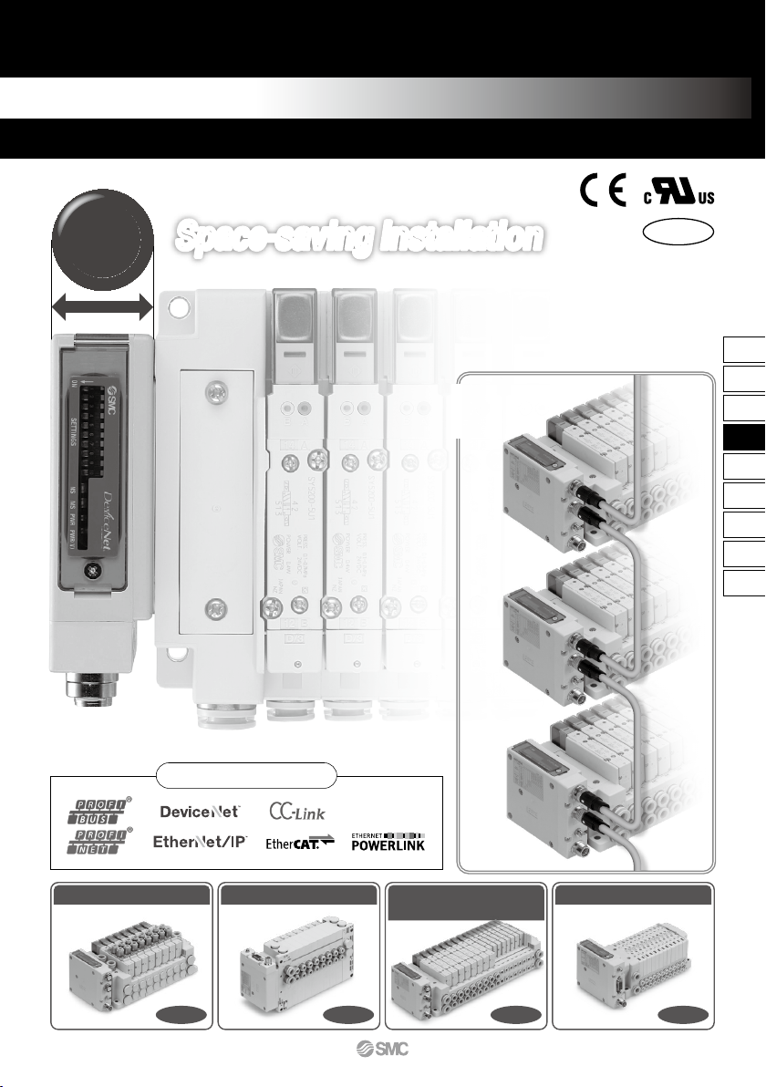
Applicable Fieldbus protocols
EX260 Series
Fieldbus System
(Output device for driving 5 port solenoid valves)
Daisy-chain wiring
communication
Space-saving InstallationSpace-saving Installation
Compact
28
mm
IP67
∗
∗
For units with D-sub connector, and when connect ed to S0700 manifolds, it is IP40 .
Drives up to 32 solenoids
789
EX12
EX140
EX180
EX260
EX250
EX600
EX500
EX510
PCA
EX
EX260
A
Page 2
PWR
BUS IN
BUS OUT
E
3/5
1P
E
3/5
1P
B4A2 B4A2 B4A2 B4A2 B4A2
PWR
BUS IN
BUS OUT
E
3/5
1P
E
3/5
1P
B4A2 B4A2 B4A2 B4A2 B4A2
Product Specification Variations
M12 communication
connector
(PROFIBUS DP)
D-sub communication
connector
(PROFIBUS DP)
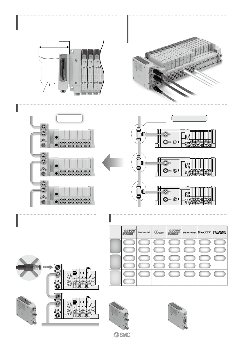
28.2 mm
81 mm
Communication connector examples
Fieldbus
EX260
Manifold length is shortened by the small
fieldbus output module (SI unit).
Wiring and piping from the same direction is possible.
(for side ported)
Effective for installation in locations where space is
limited above the valve.
Current model EX250
External branch connector is not necessary. Daisy-chain wiring is possible. Reduced wiring space
Branch connector
Current model (EX250)
External terminating resistor is not necessary.
(Only available for M12 PROFIBUS DP, CC-Link communication connectors)
ON/OFF switching is possible with an
internal terminating resistor. External
terminating resistor is not necessary.
External terminating resistor
Internal terminating
resistor
SI unit
16
32
PNP
NPN
M12
D-sub
16
32
PNP
NPN
M12
16
32
PNP
NPN
M12
16
32
PNP
NPN
M12
16
32
PNP
NPN
M12
Number of
outputs
Output
polarity
Communication
connector
16
32
PNP
NPN
M12
16
32
PNP
M12
790
A
Page 3
SY3000
SY5000
SY7000
S0700
SV1000
SV2000
SV3000
VQC1000
VQC2000
VQC4000
VQC5000
0.19
0.17
0.20
0.39
0.35
0.18
0.21
0.30
0.30
0.38
0.31
1.6
3.6
5.9
0.37
1.1
2.4
4.3
1.0
3.2
7.3
17
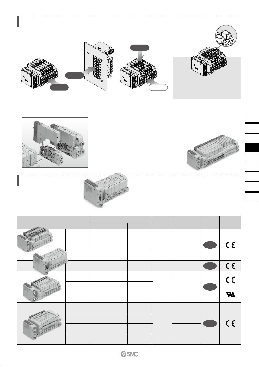
Series
Power
consumption
(W)
Enclosure Standards
Flow rate characteristics (4/2→5/3)
C [dm
3
/(s·bar)] b
Maximum
number of
solenoids
Applicable Valve Series
Note) For units with D-sub communication connector, it is IP40.
32
32
32
24
0.35 (standard)
0.1 (with powersaving circuit)
[Starting 0.4,
Holding 0.1]
0.6
0.95 (standard)
0.4 (Low wattage type)
0.4 (standard)
0.35
®
IP67
IP40
IP67
IP67
Side ported
Side ported
Bottom ported
Top ported
<Example of Use>
Valve piping direction variations
SY3000/5000/7000 Series
Pressure switch
Piping is possible from 3 directions.
Mixed mounting of top ported and side ported is possible.
By mounting top ported valves on side
ported and bottom ported type manifolds,
it is possible to detect the output of the
A/B port with a pressure switch.
Valves can be freely connected up to 24 stations.
Mixed valve sizes manifold
Valves with different sizes,
SY3000 and SY5000 or SY5000
and SY7000, can be mounted
on the same
manifold.
It is possible to connect only
the number of valves required,
from 1 to 24 stations, to suit
the application.
(Maximum number of
solenoids connected: 32)
7 mm width valves
can be connected.
It is possible to connect only the number of 7 mm
width valves required, from 1 to 24 stations.
(Maximum number of solenoids connected: 32)
S0700 Series
791
EX12
EX140
EX180
EX260
EX250
EX600
EX500
EX510
PCA
EX
EX260
Page 4
M12
DN1
DN2
DN3
DN4
PR1
PR2
PR3
PR4
PR5
PR6
PR7
PR8
MJ1
MJ2
MJ3
MJ4
EC1
EC2
EC3
EC4
PN1
PN2
PN3
PN4
EN1
EN2
EN3
EN4
PL1
PL3
DeviceNet™
PROFIBUS DP
EtherCAT
PROFINET
POWERLINK
SI unit output polarity
32
16
32
16
32
16
32
16
32
16
32
16
32
16
32
16
M12
M12
D-sub
Note)
M12
M12
EtherNet/IP™
M12
M12
Source/PNP (Negative common)
Sink/NPN (Positive common)
Source/PNP (Negative common)
Sink/NPN (Positive common)
Source/PNP (Negative common)
Sink/NPN (Positive common)
Source/PNP (Negative common)
Sink/NPN (Positive common)
Source/PNP (Negative common)
Sink/NPN (Positive common)
Source/PNP (Negative common)
Sink/NPN (Positive common)
Source/PNP (Negative common)
Sink/NPN (Positive common)
Source/PNP (Negative common)
Sink/NPN (Positive common)
Source/PNP (Negative common)
Sink/NPN (Positive common)
Source/PNP (Negative common)
Sink/NPN (Positive common)
Source/PNP (Negative common)
Sink/NPN (Positive common)
Source/PNP (Negative common)
Sink/NPN (Positive common)
Source/PNP (Negative common)
Sink/NPN (Positive common)
Source/PNP (Negative common)
Sink/NPN (Positive common)
Source/PNP (Negative common)
QAN
QA
QBN
QB
NAN
NA
NBN
NB
NCN
NC
NDN
ND
VAN
VA
VBN
VB
DAN
DA
DBN
DB
FAN
FA
FBN
FB
EAN
EA
EBN
EB
GAN
GBN
Communication protocol
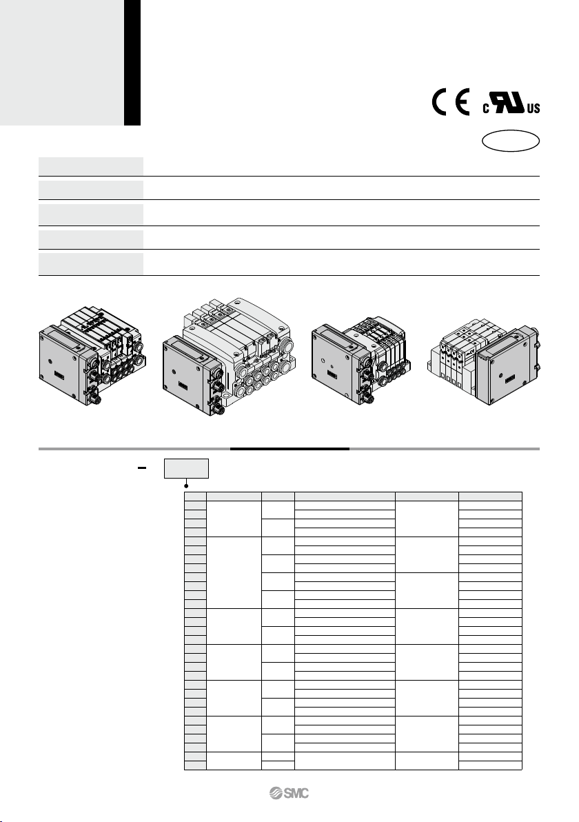
Compact design
Compact design for space saving
Number of outputs
Each 32/16 digital output type available in the series
Enclosure
IP67 (For units with D-sub connector, and when connected with S0700 manifolds, it is IP40.)
Output polarity
Each negative common (PNP) / positive common (NPN) type available in the series
(SI Unit compatible with POWERLINK is only negative common (PNP) type.)
Internal terminating resistor
ON/OFF switching is possible with an internal terminating resistor for communication.
(Only for units compatible with M12 PROFIBUS DP, CC-Link communication connectors)
SY3000/5000/7000 VQC1000/2000/4000/5000 S0700 SV1000/2000/3000
D
D
D
D
How to Order SI Units
PR1
EX260 S
Note)
Note) The SY3000/5000/7000, VQC1000/2000/4000/5000, and S0700 are not yet UL-compatible.
CC-Link
®
RoHS
Protocol
Symbol
Number of outputs
Communication connector
Manifold symbol
EX260 Series
SI Unit/For Output
Note) Enclosure is IP40 when the communication connector is D-sub.
792
A
Page 5
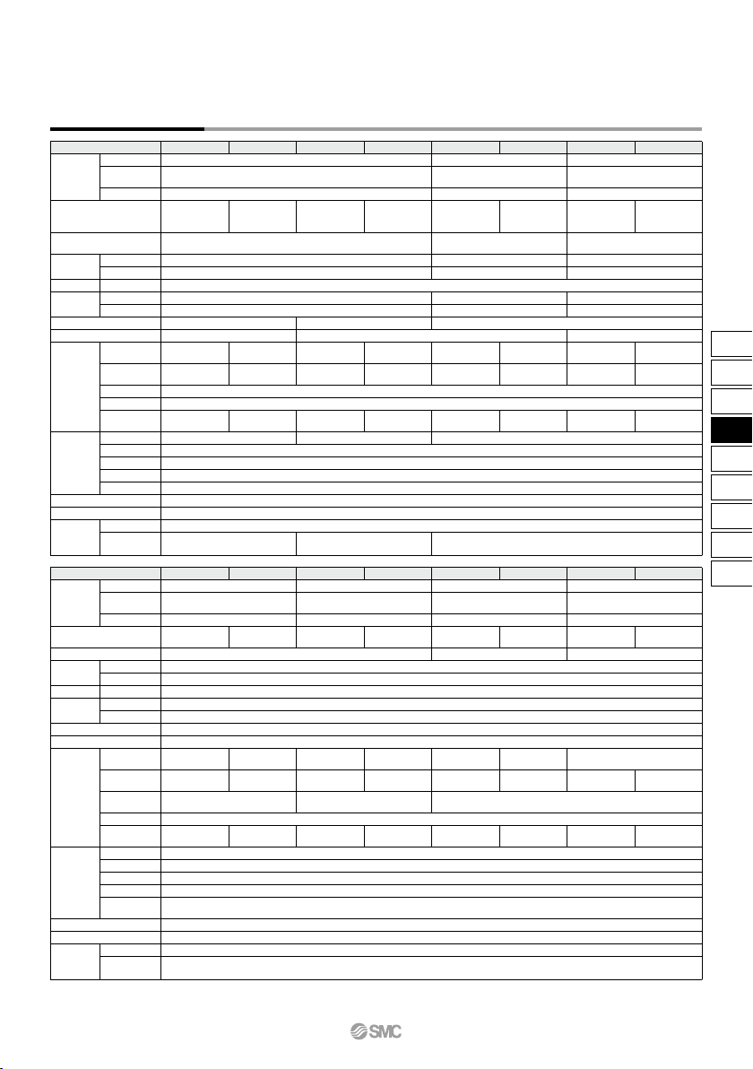
SI Unit Specifications
Model
EX260-SPR1/3 EX260-SPR2/4 EX260-SPR5/7 EX260-SPR6/8 EX260-SDN1/3 EX260-SDN2/4 EX260-SMJ1/3 EX260-SMJ2/4
125 k/250 k/500 kbps
156 k/625 k/
2.5 M/5 M/10 Mbps
M12
Built-in
—
—
22.8 to 26.4 VDC
11 to 25 VDC
100 mA or less
Applicable
system
I/O occupation area
(Inputs/Outputs)
Communication speed
Power supply
for control
Power supply for output
Communication connector specification
Terminating resistor switch
Power supply for
communication
Output
Environmental
resistance
Standards
Weight
Mounting screw
Accessories
IP67 IP40 IP67
–10 to 50°C
35 to 85%RH (No condensation)
500 VAC for 1 minute between terminals and housing
10 MΩ or more (500 VDC measured via megohmmeter) between terminals and housing
CE marking, UL (CSA) compatible
200 g
2 pcs.
24 VDC
Power supply voltage
Internal current consumption
Power supply voltage
Power supply voltage
Internal current consumption
Protocol
Version
Note 1)
Configuration file
Note 3)
Supplied current
Output type
Number of outputs
Load
Supplied voltage
Enclosure
Operating temperature range
Operating humidity range
Withstand voltage
Insulation resistance
Seal cap (for M12
connector socket)
Source/PNP
(Negative common)
Sink/NPN
(Positive common)
Source/PNP
(Negative common)
Sink/NPN
(Positive common)
Source/PNP
(Negative common)
Sink/NPN
(Positive common)
SPR1: 32 points
SPR3: 16 points
SPR2: 32 points
SPR4: 16 points
SPR5: 32 points
SPR7: 16 points
SPR6: 32 points
SPR8: 16 points
SDN1: 32 points
SDN3: 16 points
SDN2: 32 points
SDN4: 16 points
SPR1: 0/32
SPR3: 0/16
SPR2: 0/32
SPR4: 0/16
SPR5: 0/32
SPR7: 0/16
SPR6: 0/32
SPR8: 0/16
SDN1: 0/32
SDN3: 0/16
SDN2: 0/32
SDN4: 0/16
SMJ1: 32/32
SMJ3:
32/32
(1 station, remote I/O stations)
SMJ2: 32/32
SMJ4:
32/32
(1 station, remote I/O stations)
SPR1: Max. 2.0 A
SPR3: Max. 1.0 A
SPR2: Max. 2.0 A
SPR4: Max. 1.0 A
SPR5: Max. 2.0 A
SPR7: Max. 1.0 A
SPR6: Max. 2.0 A
SPR8: Max. 1.0 A
SDN1: Max. 2.0 A
SDN3: Max. 1.0 A
SDN2: Max. 2.0 A
SDN4: Max. 1.0 A
EX9-AWTS (1 pc.) — EX9-AWTS (1 pc.)
D-sub M12
None Built-in
Volume 1(Edition 3.5)
Volume 3(Edition 1.5)
9.6 k/19.2 k/45.45 k/93.75 k/
187.5 k/500 k/1.5 M/3 M/6 M/12 Mbps
21.6 to 26.4 VDC
100 mA or less
—
—
—
—
21.6 to 26.4 VDC
100 mA or less
PROFIBUS DP
DeviceNet™
CC-Link
DP-V0 Ver.1.10
—
GSD file EDS file
Source/PNP
(Negative common)
Sink/NPN
(Positive common)
SMJ1: 32 points
SMJ3: 16 points
SMJ2: 32 points
SMJ4: 16 points
SMJ1: Max. 2.0 A
SMJ3: Max. 1.0 A
SMJ2: Max. 2.0 A
SMJ4: Max. 1.0 A
Solenoid valve with protective circuit for surge voltage of 24 VDC/1.5 W or less (SMC)
Model
EX260-SEC1/3 EX260-SEC2/4 EX260-SPN1/3 EX260-SPN2/4 EX260-SEN1/3 EX260-SEN2/4
Applicable
system
I/O occupation area
(Inputs/Outputs)
Communication speed
Power supply
for control
Power supply for output
Communication connector specification
Terminating resistor switch
Power supply for
communication
Output
Environmental
resistance
Standards
Weight
Mounting screw
Accessories
IP67
–10 to 50°C
35 to 85%RH (No condensation)
500 VAC for 1 minute between terminals and housing
CE marking, UL (CSA) compatible
200 g
2 pcs.
10 MΩ or more (500 VDC measured via megohmmeter) between terminals and housing
24 VDC
Power supply voltage
Internal current consumption
Power supply voltage
Power supply voltage
Internal current consumption
Protocol
Version
Note 1)
Configuration file
Note 3)
Supplied voltage
Output type
Number of outputs
Load
Supplied voltage
Enclosure
Operating temperature range
Operating humidity range
Withstand voltage
Insulation
resistance
Seal cap (for M12
connector socket)
Source/PNP
(Negative common)
Sink/NPN
(Positive common)
Source/PNP
(Negative common)
Sink/NPN
(Positive common)
Source/PNP
(Negative common)
Sink/NPN
(Positive common)
SEC1: 32 points
SEC3: 16 points
SEC2: 32 points
SEC4: 16 points
SPN1: 32 points
SPN3: 16 points
SPN2: 32 points
SPN4: 16 points
SEN1: 32 points
SEN3: 16 points
SEN2: 32 points
SEN4: 16 points
SEC1: 0/32
SEC3: 0/16
SEC2: 0/32
SEC4: 0/16
SPN1: 0/32
SPN3: 0/16
SPN2: 0/32
SPN4: 0/16
SEN1: 16/32
SEN3: 16/16
SEN2: 16/32
SEN4: 16/16
SEC1: Max. 2.0 A
SEC3: Max. 1.0 A
SEC2: Max. 2.0 A
SEC4: Max. 1.0 A
SPN1: Max. 2.0 A
SPN3: Max. 1.0 A
SPN2: Max. 2.0 A
SPN4: Max. 1.0 A
SEN1: Max. 2.0 A
SEN3: Max. 1.0 A
SEN2: Max. 2.0 A
SEN4: Max. 1.0 A
EX9-AWTS (1 pc.)
Volume 1(Edition 3.8)
Volume 2(Edition 1.9)
21.6 to 26.4 VDC
100 mA or less
22.8 to 26.4 VDC
—
—
M12
None (Not required)
10 M/100 Mbps
Note 2)
100 Mbps
Note 2)
EtherCAT
Note 2)
EtherNet/IP™
Note 2)
Conformance
Test Record V.1.1
XML file
PROFINET
Note 2)
PROFINET Specification
Version 2.2
GSD file EDS file
Solenoid valve with protective circuit for surge
voltage of 24 VDC/1.5 W or less (SMC)
Solenoid valve with protective circuit for surge
voltage of 24 VDC/1.0 W or less (SMC)
Solenoid valve with protective circuit for surge
voltage of 24 VDC/1.5 W or less (SMC)
EX260-SPL1 EX260-SPL3
Source/PNP
(Negative common)
32 16
16/32 16/16
Max. 2 A Max. 1 A
EPSG DS 301 Version 1.2.0
100 Mbps
Note 2)
POWERLINK
XDD file
Note 1) Please note that the version is subject to change.
Note 2) Use a CAT5 or higher transmission cable for EtherCAT, PROFINET, EtherNet/IP™, POWERLINK.
Note 3) Each file can be downloaded from the SMC website, http://www.smcworld.com
For Output EX260 Series
793
EX12
EX140
EX180
EX260
EX250
EX600
EX500
EX510
PCA
EX
EX260
A
Page 6

D-sub communication connector typeM12 communication connector type
90.9
28.2
102.4
90.9
102.4
28.2
21 20.6 16.4 9
76.5
28.75 29.25 9
76.5
SI Unit Dimensions
Part no.
Communication protocol
EX260-SPR1/-SPR2
-SPR3/-SPR4
PROFIBUS DP
5 pins, socket, B code
5 pins, plug, B code
5 pins, plug, A code
Note) The setting switch varies depending on the model.
Refer to the operation manual for details.
Please download it via the SMC website, http://www.smcworld.com
EX260-SDN
DeviceNet™
5 pins, socket, A code
5 pins, plug, A code
4 pins, plug, A code
EX260-SMJ
CC-Link
EX260-SEC
EX260-SPN
EX260-SEN
EX260-SPL
EtherCAT
PROFINET
EtherNet/IP™
POWERLINK
M3
Communication connector (M12) BUS OUT
Communication connector (M12) BUS IN
Ground terminal
Power connector (M12)
<Setting switch>
• Address switch
• Communication speed switch
• Terminating resistor switch
• Others
<LED indication>
• Communication state
• Unit power supply state
• Valve power supply state
Part no.
Communication protocol
EX260-SPR5/-SPR6/-SPR7/-SPR8
PROFIBUS DP
M3
9 pins, socket
5 pins, plug, A code
Ground terminal
Communication connector (D-sub) BUS IN/OUT
Power connector (M12)
D-sub communication connector type
Functions of SI Unit Parts
<Connector>
M12 communication connector type
<LED indication and setting switch>
5 pins, socket, A code
Note1)
4 pins, plug, A code
5 pins, plug, B code
4 pins, socket, D code
4 pins, socket, D code
5 pins
Note2)
, 4 pins
Note3)
,
plug, A code
EX260 Series
Note 1) Recommended mating M12
4-pin plug, part no.
PCA-1567717.
Note 2) For EtherCAT, PROFINET,
POWERLINK
Note 3) For EtherNet/IP™
794
A
Page 7

White/Orange
Orange
White/Green
Green
Accessories
q Communication cable with connector
For SI units compatible with
PROFIBUS DP, DeviceNet™, CC-Link
For SI units compatible with EtherCAT, PROFINET, EtherNet/IP™, POWERLINK
Refer to page 907 for details.
020EX9 AC EN
Cable length (L)
1000 [mm]
2000 [mm]
3000 [mm]
5000 [mm]
10000 [mm]
010
020
030
050
100
PSRJ
M12 plug (straight) ⇔ RJ-45 connector
PSRJ
Plug connector
pin arrangement
D code
Connections (Straight cable)
M12
RJ-45
Plug connector
pin arrangement
1
2
3
4
5
6
7
8
Terminal
no.
1
2
3
4
1
2
3
4
5
6
7
8
Terminal
no.
Shield
Pair
Pair
Core wire
colors
Connector specification
For SI units compatible with EtherCAT, PROFINET, EtherNet/IP™, POWERLINK
PCA 1446566
For SI units compatible with EtherCAT, PROFINET, EtherNet/IP™, POWERLINK
PCA 1446553
5000 [mm]
1446566
Cable length
Fieldwireable connector
(ø
6.5)
50500047.3
ø14.8
Plug connector
pin arrangement
D code
12
3 4
M12
SPEEDCON
ø
17.5
ø
19
≈ 61
Width across
flats 16
M12
For Output EX260 Series
12
3 4
Plug connector
pin arrangement
D code
12
3 4
1
2
3
4
White: RD+
Blue: RD–
Yellow: TD+
Orange: TD–
Connections
Terminal
no.
Wire guide color
Width across
flats 13
ø6.4
(47.3) (44)
L
ø14.8
Item Specifications
Cable O.D.
Nominal cross section
Wire diameter (Including insulator)
Min. bending radius
ø6.5 mm
AWG22
1.5 mm
45.5 mm
Applicable cable
Cable O.D.
Cable cross section (Stranded wire)
4.0 to 8.0 mm
0.14 to 0.34 mm
2
/AWG26 to 22
Note) The table above shows the specifications for the applicable
cable. Adaptation for the connector may vary on account of
the conductor construction of the electric wire.
795
EX12
EX140
EX180
EX260
EX250
EX600
EX500
EX510
PCA
EX
EX260
A
Page 8

w Power cable with connector (for SI units)
Accessories
EX500 AP
2
4 3
Socket connector
pin arrangement
A code
Socket connector
pin arrangement
A code
1
1
2
3
4
5
Terminal
no.
Core wire
colors
M12
Connections (PROFIBUS DP/EtherCAT/PROFINET/POWERLINK)
Cable length (L)
1000 [mm]
5000 [mm]
010
050
Connector specification
Straight
Angle
S
A
S
050
For SI units compatible with PROFIBUS DP, DeviceNet™, EtherCAT, PROFINET, EtherNet/IP™, POWERLINK
Brown: 24 VDC +10%/–5% (Solenoid valve power supply)
White: 0 V (Solenoid valve power supply)
Blue: 24 VDC ±10% (Control power supply)
Black: 0 V (Control power supply)
Green/Yellow: Not connected
1
2
3
4
5
Terminal
no.
Core wire
colors
Connections (DeviceNet™, EtherNet/IP™)
Brown: Not connected
Note 1)
, 24 VDC ±10% (Control power supply)
Note 2)
White: 24 VDC +10%/–5%
(Solenoid valve power supply)
Blue: Not connected
Note 1)
, 0 V (Control power supply)
Note 2)
Black: 0 V (Solenoid valve power supply)
Green/Yellow: Not connected
Straight connector type
2
4 3
5
1
M12
Angle connector type
5
SPEEDCON
PCA
Cable length (L)
1500 [mm]
3000 [mm]
5000 [mm]
1401804
1401805
1401806
1401804
4 3
21
ø14.8
M12
SPEEDCON
44.5 L 50
ø5.0
5
Socket connector
pin arrangement
A code
Note 1) For DeviceNet™
Note 2) For EtherNet/IP™
1
2
3
4
5
Terminal
no.
Core wire
colors
Connections (PROFIBUS DP/EtherCAT/PROFINET/POWERLINK)
Brown: 24 VDC +10%/–5% (Solenoid valve power supply)
White: 0 V (Solenoid valve power supply)
Blue: 24 VDC ±10% (Control power supply)
Black: 0 V (Control power supply)
Gray: Not connected
1
2
3
4
5
Terminal
no.
Core wire
colors
Connections (DeviceNet™, EtherNet/IP™)
Brown: Not connected
Note 1)
, 24 VDC ±10% (Control power supply)
Note 2)
White: 24 VDC +10%/–5%
(Solenoid valve power supply)
Blue: Not connected
Note 1)
, 0 V (Control power supply)
Note 2)
Black: 0 V (Solenoid valve power supply)
Gray: Not connected
Note 1) For DeviceNet™
Note 2) For EtherNet/IP™
EX260 Series
ø14.9
25.3
28.3
30
5
50
L
ø6
ø14.9
40.7
27
L
ø6
30
5
50
Item Specifications
Cable O.D.
Nominal cross section
Wire diameter (Including insulator)
Min. bending radius
ø6 mm
AWG22
1.5 mm
40 mm
Item Specifications
Cable O.D.
Nominal cross section
Wire diameter (Including insulator)
Min. bending radius
ø6 mm
AWG22
1.5 mm
40 mm
Item Specifications
Cable O.D.
Nominal cross section
Wire diameter (Including insulator)
Min. bending radius
ø5.0 mm
AWG22
1.27 mm
21.7 mm
796
B
Page 9

w Power cable with connector (for SI units)
Accessories
e Seal cap: For M12 connector socket
EX9 AW
Use this on ports that are not being used for communication connector (M12
connector socket).
Use of this seal cap maintains the integrity of the IP67 enclosure.
Note) Tighten the seal cap with the prescribed tightening torque. (For M12: 0.1 N·m)
TS
Connector type
For M12 connector socket (10 pcs.)
For M12 connector socket
M12 x 1
14
10.2
14
For
SI units compatible with
CC-Link
Straight connector type
TS
EX9 AC 1
Cable length (L)
1000 [mm]
3000 [mm]
5000 [mm]
010
030
050
050
SPEEDCON
PCA
Cable length (L)
1500 [mm]
3000 [mm]
5000 [mm]
1401807
1401808
1401809
1401807
2
4 3
5
1
Socket connector
pin arrangement
B code
M12
48.1
L
30505
ø6.4
Connections
1
2
3
4
5
Terminal
no.
Cable core
wire colors
4 3
21
M12
SPEEDCON
ø14.8
50L44.5
ø5.0
5
Socket connector
pin arrangement
B code
Brown: 24 VDC +10%/–5% (Solenoid valve power supply)
White: 0 V (Solenoid valve power supply)
Blue: 24 VDC ±10% (Control power supply)
Black: 0 V (Control power supply)
Green/Yellow: Not connected
Connections
1
2
3
4
5
Terminal
no.
Cable core
wire colors
Brown: 24 VDC +10%/–5% (Solenoid valve power supply)
White: 0 V (Solenoid valve power supply)
Blue: 24 VDC ±10% (Control power supply)
Black: 0 V (Control power supply)
Gray: Not connected
For Output EX260 Series
Item Specifications
Cable O.D.
Nominal cross section
Wire diameter (Including insulator)
Min. bending radius
ø6.4 mm
AWG22
1.65 mm
59 mm
Item Specifications
Cable O.D.
Nominal cross section
Wire diameter (Including insulator)
Min. bending radius
ø5.0 mm
AWG22
1.27 mm
21.7 mm
797
EX12
EX140
EX180
EX260
EX250
EX600
EX500
EX510
PCA
EX
EX260
A
Page 10

Design/Selection
1. Use this product within the specification range.
Using beyond the specified specifications range can cause
fire, malfunction, or damage to the system.
Check the specifications before operation.
2. When using for an interlock circuit:
• Provide a multiple interlock system which is
operated by another system (such as mechanical
protection function).
• Perform an inspection to confirm that it is working
properly.
This may cause possible injury due to malfunction.
Warning
Mounting
4. When lifting a large size manifold solenoid valve
unit, take care to avoid causing stress to the valve
connection joint.
The connection parts of the unit may be damaged. Because
the unit may be heavy, carrying and installation should be
performed by more than one operator to avoid strain or injury.
5. When placing a manifold, mount it on a flat surface.
Torsion in the whole manifold can lead to trouble such as air
leakage or defective insulation.
Wiring
1. Check the grounding to maintain the safety of the
reduced wiring system and for anti-noise
performance.
Provide a specific grounding as close to the unit as possible to
minimize the distance to grounding.
2. Avoid repeatedly bending or stretching the cable
and applying a heavy object or force to it.
Wiring applying repeated bending and tensile stress to the
cable can break the circuit.
3. Avoid miswiring.
If miswired, there is a danger of malfunction or damage to the
reduced wiring system.
4. Do not wire while energizing the product.
There is a danger of malfunction or damage to the reduced
wiring system or output device.
5. Avoid wiring the power line and high pressure line
in parallel.
Noise or surge produced by signal line resulting from the power
line or high pressure line could cause malfunction.Wiring of the
reduced wiring system or output device and the power line or
high pressure line should be separated from each other.
6. Check the wiring insulation.
Defective insulation (contact with other circuits, improper
insulation between terminals, etc.) may cause damage to the
reduced wiring system or output device due to excessive
voltage and current.
7. When a reduced wiring system is installed in
machinery/equipment, provide adequate protection
against noise by using noise filters, etc.
Noise in signal lines may cause malfunction.
1. When applicable to UL, use a Class 2 power supply unit
conforming to UL1310 for direct current power supply.
2. Use this product within the specified voltage range.
Using beyond the specified voltage range is likely to cause the
units and connecting devices to be damaged or to malfunction.
3. Do not install a unit in a place where it can be used
as a foothold.
Applying any excessive load such as stepping on the unit by
mistake or placing a foot on it, will cause it to break.
4. Keep the surrounding space free for maintenance.
When designing a system, take into consideration the amount
of free space needed for performing maintenance.
5. Do not remove the name plate.
Improper maintenance or incorrect use of operation manual
can cause failure and malfunction. Also, there is a risk of
losing conformity with safety standards.
1. When handling and assembling units:
• Do not apply excessive force to the unit when
disassembling.
The connecting portions of the unit are firmly joined with
seals.
• When joining units, take care not to get fingers
caught between units.
Injury can result.
2. Do not drop, bump, or apply excessive impact.
Otherwise, the unit can become damaged, malfunction, or fail
to function.
3. Observe the tightening torque range.
Tightening outside of the allowable torque range will likely
damage the screw.
IP67 cannot be guaranteed if the screws are not tightened to
the specified torque.
Mounting
EX260 Series
Specific Product Precautions 1
Be sure to read this before handling the products. Refer to back page 50 for Safety
Instructions and pages 3 to 9 for 3/4/5 Port Solenoid Valve Precautions.
Caution
Caution
Caution
Caution
798
Page 11

Wiring
Operating Environment
1. Do not use in an atmosphere containing an
inflammable gas or explosive gas.
Use in such an atmosphere is likely to cause a fire or
explosion. This system is not explosion-proof.
Operating Environment
2. Provide adequate protection when operating in
locations such as the following.
Failure to do so may cause damage or malfunction.
The effect of countermeasures should be checked in individual
equipment and machine.
1) Where noise is generated by static electricity, etc.
2) Where there is a strong electric field
3) Where there is a danger of exposure to radiation
4) When in close proximity to power lines or high voltage lines
3. Do not use in an environment where oil and chemicals
are used.
Operating in environments with coolants, cleaning solvents,
various oils or chemicals may cause adverse effects (damage,
malfunction) to the unit even in a short period of time.
4. Do not use in an environment where the product
could be exposed to corrosive gas or liquid.
This may damage the unit and cause it to malfunction.
5. Do not use in locations with sources of surge
generation.
Installation of the unit in an area around the equipment
(electromagnetic lifters, high frequency induction furnaces,
welding machine, motors, etc.), which generates the large
surge voltage could cause to deteriorate an internal circuitry
element of the unit or result in damage. Implement
countermeasures against the surge from the generating
source, and avoid touching the lines with each other.
6. The product is CE marked, but not immune to
lightning strikes. Take measures against lightning
strikes in your system.
7. Keep dust, wire scraps and other extraneous
material from getting inside the product.
This may cause malfunction or damage.
8. Mount the unit in such locations, where no vibration
or shock is affected.
This may cause malfunction or damage.
9. D o not use in places where there are cyclic
temperature changes.
In case that the cyclic temperature is beyond normal
temperature changes, the internal unit is likely to be adversely
effec-ted.
10. Do not use in direct sunlight.
Do not use in direct sunlight. It may cause malfunction or
damage.
11. Use this product within the specified ambient
temperature range.
This may cause malfunction.
12. Do not use in places where there is radiated heat
around it.
Such a place is likely to cause malfunction.
1. Select the proper type of enclosure according to the
environment of operation.
IP67 is achieved when the following conditions are met.
1) Provide appropriate wiring between all units using electrical
wiring cables, communication connectors and cables with
M12 connectors.
2) Suitable mounting of each unit and manifold valve.
3) Be sure to mount a seal cap on any unused connectors.
If using in an environment that is exposed to water splashes,
please take measures such as using a cover.
When the enclosure is IP40, do not use in an operating
environment or atmosphere where it may come in contact with
corrosive gas, chemical agents, seawater, water, or water vapor.
When connected to the EX260-SPR5/6/7/8, manifold
enclosure is IP40.
Caution
Caution
Caution
Warning
8. When connecting wires of output device, prevent
water, solvent or oil from entering inside the
connector section.
This can cause damage, equipment failure or malfunction.
9. Avoid wiring patterns in which excessive stress is
applied to the connector.
This may cause malfunction or damage to the unit due to
contact failure.
10. Select connectors that are ø16 or less if mounting
manifolds directly using fieldwireable connectors
for SI unit power supply wiring.
Using large diameter connectors causes interference with the
mounting surface.
The following cables with connectors are recommended.
For EX260-SPR/-SDN/-SEC/-SPN/-SEN/-SPL
<Cable with connector>
EX500-AP-
PCA-1401804/-1401805/-1401806
For EX260-SMJ
<Cable with connector>
EX9-AC-1
PCA-1401807/-1401808/-1401809
EX260 Series
Specific Product Precautions 2
Be sure to read this before handling the products. Refer to back page 50 for Safety
Instructions and pages 3 to 9 for 3/4/5 Port Solenoid Valve Precautions.
799
EX12
EX140
EX180
EX260
EX250
EX600
EX500
EX510
PCA
EX
EX260
A
Page 12

Adjustment/Operation
Warning
1. Do not perform operation or setting with wet hands.
There is a risk of electrical shock.
Maintenance
1. Do not disassemble, modify (including circuit board
replacement) or repair this product.
Such actions are likely to cause injuries or breakage.
2. When an inspection is performed,
• Turn off the power supply.
• Stop the air supply, exhaust the residual pressurein
piping and verify that the air is released before
performing maintenance work.
Unexpected malfunction of system components and injury
can result.
Trademark
DeviceNet™ is a trademark of ODVA.
EtherNet/IP™ is a trademark of ODVA.
EtherCAT
®
is registered trademark and patented technology, licensed by Beckhoff Automation GmbH, Germany.
1. Use a watchmakers’ screwdriver with thin blade for
the setting of each switch of the SI unit.
When setting the switch, do not touch other unrelated
parts.
This may cause parts damage or malfunction due to a short
circuit.
2.
Provide adequate setting for the operating conditions.
Failure to do so could result in malfunction.
Refer to the operation manual for setting of the switches.
3. For details on programming and address setting,
refer to the manual from the PLC manufacturer.
The content of programming related to protocol is designed by
the manufacturer of the PLC used.
4. For the EX260-SPN, the side of the SI unit may
become hot.
It may cause burns.
1. When handling and replacing the unit:
• Do not apply excessive force to the unit when
disassembling.
The connecting portions of the unit are firmly joined with
seals.
• When joining units, take care not to get fingers
caught between units.
Injury can result.
2. Perform periodic inspection.
Unexpected malfunction in the system composition devices is
likely to occur due to malfunction of machinery or equipment.
3. A fter maintenance, make sure to perform an
appropriate functionality inspection.
In cases of abnormality such as faulty operation, stop
operation. Unexpected malfunction in the system composition
devices is likely to occur.
4. Do not use benzene and thinner for cleaning units.
Damage to the surface or erasure of the display can result.
Wipe off any stains with a soft cloth.
If the stain is persistent, wipe off with a cloth soaked in a
dilute solution of neutral detergent and wrung out tightly,
and then finish with a dry cloth.
Other
1. Refer to the catalog of each series for Common
Precautions and Specific Product Precautions on
manifold solenoid valves.
Caution
Caution
Caution
Warning
EX260 Series
Specific Product Precautions 3
Be sure to read this before handling the products. Refer to back page 50 for Safety
Instructions and pages 3 to 9 for 3/4/5 Port Solenoid Valve Precautions.
800
Page 13

Contact our sales office for delivery dates
and prices as this is a special model.
Specialized Product
IO-Link Compatible SI Unit
EX260-SIL1-X207/X210
IO-Link communication enables users to check
Features
PLC
unit information and monitor unit status, in
addition to ON/OFF valve control.
PC
Point to Group
P. G . information
IO-Link is an open communication interface technology between the sensor/actuator and the I/O terminal that is an international standard IEC61131-9.
Various fieldbusses
IO-Link master
IO-Link communication
IO-Link Compatible Device:
SI Unit
EX260-SIL1-X207/X210
Send and receive ON/OFF signals + unit information/status
Sending and receiving of unit information, error
detection, or condition monitoring data
<Unit Information> Manufacturer’s name, product number, version information
<Error Detection> Output wiring disconnection, short circuit
<Conditioning Monitoring> Number of valve operations, operation threshold exceeded
Application Example
Supporting periodic cylinder maintenance
The replacement time of the cylinder connected to the valve
can be predicted by counting the number of valve operation
instructions. This enables periodic maintenance to be
performed before any unexpected cylinder failure occurs.
Currently at 10 million
operations
Currently at 5 million
operations
Port class B compliant: X210
Port class A compliant: X207
Supports data update cycles of 1 ms or less
Shortest data update cycle: 0.8 ms
The data update cycle can be set for the IO-Link master based
on the SI unit’s shortest data update cycle of 0.8 ms.
IO-Link master and SI unit can be connected with one cable
Signal wire and valve power supply wire can be connected
with the same cable.
Also applicable to the types in which the signal wire and valve
power supply wire are connected with individual cables.
(Port class A compliant: X207 specifications)
(Port class B compliant: X210 specifications)
Uses 4-wire or 5-wire unshielded cables
Special communication cables are not necessary.
A conventional 4-wire or 5-wire unshielded cable can be used
for input and output of sensors, switches, etc.
(Recommended specifications: Conductor resistance 3 Ω, Wireto-wire capacitance 3 nF or less, 20 m or less)
Caution
©2017 SMC Corporation All Rights Reserved
To ensure the safest possible operation of this product, please be sure to thoroughly read the
“Safety Instructions” in our “Best Pneumatics” catalog before use.
4-14-1, SOTO-KANDA, CHIYODA-KU, TOKYO 101-0021, JAPAN
URL: http://www.smcworld.com
SP165X-022E
P: VS
Page 14

IO-Link Compatible SI Unit
EX260-SIL1-X207/X210
Specifications
Specialized Product
Point to Group
P. G . information
Item
Protocol IO-Link version 1.1
Communication speed COM2 (38.4 kbps)/COM3 (230.4 kbps) (Selected by DIP switch)
IO-Link port class
(Communication connector)
IO-Link type Device
Vendor ID 131
Process data size 0 byte input/4 bytes output
Number of outputs 32 outputs
Output type PNP (Negative common)/Source
Connected load Solenoid valve with surge voltage suppressor of 24 VDC and 1.5 W or less (manufactured by SMC)
Output
Solenoid valve power supply
Residual voltage 0.4 VDC or less
Control unit power supply
Weight 200 g or less
Standards CE marking, UL/CSA
(Valve power supplied from the valve power supply connector)
EX260-SIL1-X207 EX260-SIL1-X210
Class A
(Valve power supplied from the communication connector)
22.8 to 26.4 VDC
2 A or less (according to the solenoid valve station specification)
18 to 30 VDC
0.1 A or less
Class B
IODD files are required to configure this product.
Please contact SMC for the IODD files.
Also, please contact SMC for the operation manual.
Wiring Specifications
Suffix Communication connector Power supply connector for solenoid valve
M12 4-pin plug, A-coded M12 5-pin plug, A-coded
No.
X207
X210
No.
1
2
3
4
M12 5-pin plug, A-coded
No.
1
2
3
4
5
Designation
L+ +24 V for control unit
— Unused
L− 0 V for control unit
C/Q IO-Link communication data
Designation
L+ +24 V for control unit
SV24V +24 V for solenoid valve
L− 0 V for control unit
C/Q IO-Link communication data
SV0V 0 V for solenoid valve
Description
Description
Designation
— Unused
1
SV24V +24 V for solenoid valve
2
— Unused
3
— Unused
4
SV0V 0 V for solenoid valve
5
Description
Page 15

Output connector (34 pins, Receptacle)
Output common (0 V)
Solenoid output 0
Solenoid output 2
Solenoid output 4
Solenoid output 6
Solenoid output 8
Solenoid output 10
Solenoid output 12
Solenoid output 14
Solenoid output 16
Solenoid output 18
Solenoid output 20
Solenoid output 22
Solenoid output 24
Solenoid output 26
Solenoid output 28
Solenoid output 30
Output common (0 V)
Solenoid output 1
Solenoid output 3
Solenoid output 5
Solenoid output 7
Solenoid output 9
Solenoid output 11
Solenoid output 13
Solenoid output 15
Solenoid output 17
Solenoid output 19
Solenoid output 21
Solenoid output 23
Solenoid output 25
Solenoid output 27
Solenoid output 29
Solenoid output 31
DescriptionDesignationNo. DescriptionDesignationNo.
Communication connector
Ground terminal (M3)
Power supply connector (PWR)
Output connector (34 pins)
IO-Link Compatible SI Unit
EX260-SIL1-X207/X210
How to Order
Specialized Product
Point to Group
P. G . information
EX260
Communication protocol
IL
Output specification
32 outputs, PNP (Negative common)/Source
1
IO-Link
1S IL
X207
IO-Link port class
X207
X210
IO-Link port Class A, Valve power
supplied from another connector
IO-Link port Class B
Dimensions [mm]
EX260-SIL1-X207 (The X210 is not provided with a power supply connector.)
Caution
• For dimensions when combined with the valve manifold, use the
dimensions of the valve manifold where the standard EX260 series unit
is mounted.
• Order the valve manifold separately. Specify “no SI unit” and “negative
common” for the valve manifold specifications.
 Loading...