

SMC Networks EX260-SPR1/3, EX260-SPR2/4, EX260-SPR5/7, EX260-SPR6/8, EX260-SDN1/3 Quick Start Manual
...
®
RoHS
IP67IP67 IP67 IP40
Top ported valve Bottom ported valve
Side ported valve
Mixed valve sizes manifold
7 mm width valve
Applicable Fieldbus protocols
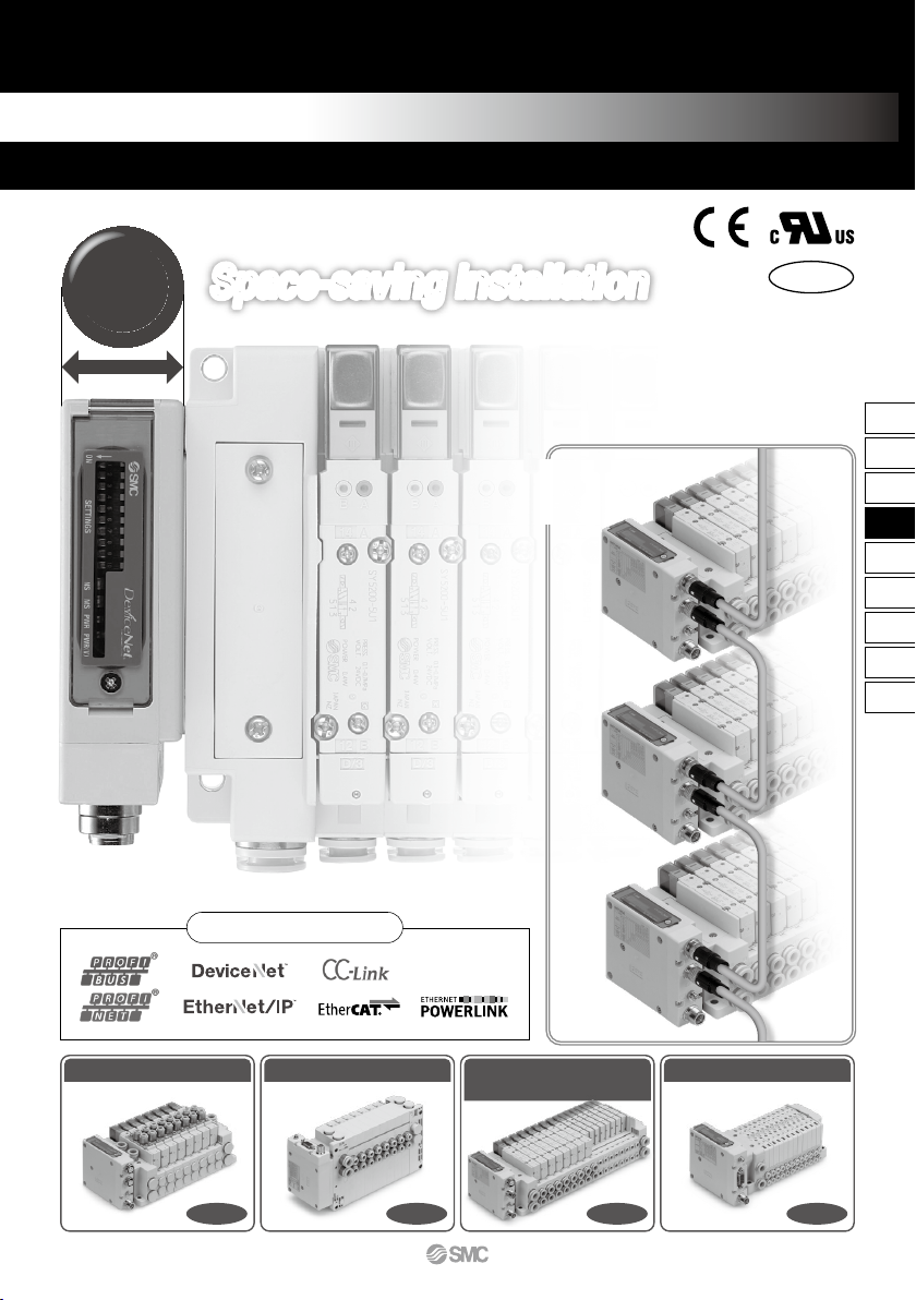
EX260 Series
Fieldbus System
(Output device for driving 5 port solenoid valves)
Daisy-chain wiring
communication
Space-saving InstallationSpace-saving Installation
Compact
28
mm
IP67
∗
∗
For units with D-sub connector, and when connect ed to S0700 manifolds, it is IP40 .
Drives up to 32 solenoids
789
EX12
EX140
EX180
EX260
EX250
EX600
EX500
EX510
PCA
EX
EX260
A
PWR
BUS IN
BUS OUT
E
3/5
1P
E
3/5
1P
B4A2 B4A2 B4A2 B4A2 B4A2
PWR
BUS IN
BUS OUT
E
3/5
1P
E
3/5
1P
B4A2 B4A2 B4A2 B4A2 B4A2
Product Specification Variations
M12 communication
connector
(PROFIBUS DP)
D-sub communication
connector
(PROFIBUS DP)
28.2 mm
81 mm
Communication connector examples
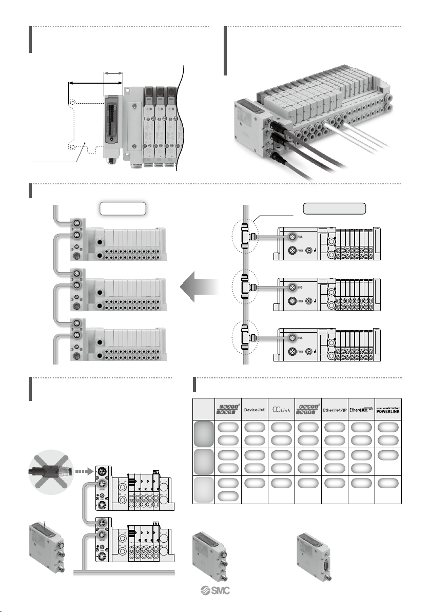
Fieldbus
EX260
Manifold length is shortened by the small
fieldbus output module (SI unit).
Wiring and piping from the same direction is possible.
(for side ported)
Effective for installation in locations where space is
limited above the valve.
Current model EX250
External branch connector is not necessary. Daisy-chain wiring is possible. Reduced wiring space
Branch connector
Current model (EX250)
External terminating resistor is not necessary.
(Only available for M12 PROFIBUS DP, CC-Link communication connectors)
ON/OFF switching is possible with an
internal terminating resistor. External
terminating resistor is not necessary.
External terminating resistor
Internal terminating
resistor
SI unit
16
32
PNP
NPN
M12
D-sub
16
32
PNP
NPN
M12
16
32
PNP
NPN
M12
16
32
PNP
NPN
M12
16
32
PNP
NPN
M12
Number of
outputs
Output
polarity
Communication
connector
16
32
PNP
NPN
M12
16
32
PNP
M12
790
A
SY3000
SY5000
SY7000
S0700
SV1000
SV2000
SV3000
VQC1000
VQC2000
VQC4000
VQC5000
0.19
0.17
0.20
0.39
0.35
0.18
0.21
0.30
0.30
0.38
0.31
1.6
3.6
5.9
0.37
1.1
2.4
4.3
1.0
3.2
7.3
17
Series
Power
consumption
(W)
Enclosure Standards
Flow rate characteristics (4/2→5/3)
C [dm
3
/(s·bar)] b
Maximum
number of
solenoids
Applicable Valve Series
Note) For units with D-sub communication connector, it is IP40.
32
32
32
24
0.35 (standard)
0.1 (with powersaving circuit)
[Starting 0.4,
Holding 0.1]
0.6
0.95 (standard)
0.4 (Low wattage type)
0.4 (standard)
0.35
®
IP67
IP40
IP67
IP67
Side ported
Side ported
Bottom ported
Top ported
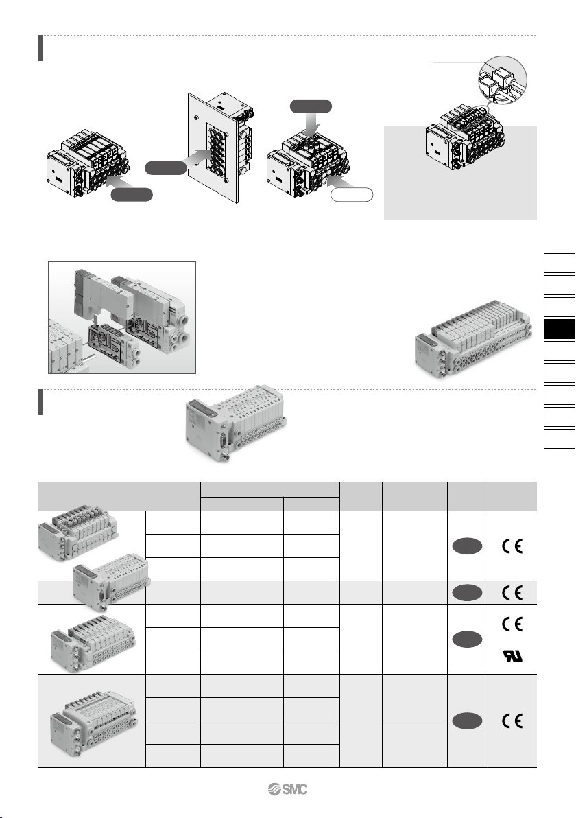
<Example of Use>
Valve piping direction variations
SY3000/5000/7000 Series
Pressure switch
Piping is possible from 3 directions.
Mixed mounting of top ported and side ported is possible.
By mounting top ported valves on side
ported and bottom ported type manifolds,
it is possible to detect the output of the
A/B port with a pressure switch.
Valves can be freely connected up to 24 stations.
Mixed valve sizes manifold
Valves with different sizes,
SY3000 and SY5000 or SY5000
and SY7000, can be mounted
on the same
manifold.
It is possible to connect only
the number of valves required,
from 1 to 24 stations, to suit
the application.
(Maximum number of
solenoids connected: 32)
7 mm width valves
can be connected.
It is possible to connect only the number of 7 mm
width valves required, from 1 to 24 stations.
(Maximum number of solenoids connected: 32)
S0700 Series
791
EX12
EX140
EX180
EX260
EX250
EX600
EX500
EX510
PCA
EX
EX260
M12
DN1
DN2
DN3
DN4
PR1
PR2
PR3
PR4
PR5
PR6
PR7
PR8
MJ1
MJ2
MJ3
MJ4
EC1
EC2
EC3
EC4
PN1
PN2
PN3
PN4
EN1
EN2
EN3
EN4
PL1
PL3
DeviceNet™
PROFIBUS DP
EtherCAT
PROFINET
POWERLINK
SI unit output polarity
32
16
32
16
32
16
32
16
32
16
32
16
32
16
32
16
M12
M12
D-sub
Note)
M12
M12
EtherNet/IP™
M12
M12
Source/PNP (Negative common)
Sink/NPN (Positive common)
Source/PNP (Negative common)
Sink/NPN (Positive common)
Source/PNP (Negative common)
Sink/NPN (Positive common)
Source/PNP (Negative common)
Sink/NPN (Positive common)
Source/PNP (Negative common)
Sink/NPN (Positive common)
Source/PNP (Negative common)
Sink/NPN (Positive common)
Source/PNP (Negative common)
Sink/NPN (Positive common)
Source/PNP (Negative common)
Sink/NPN (Positive common)
Source/PNP (Negative common)
Sink/NPN (Positive common)
Source/PNP (Negative common)
Sink/NPN (Positive common)
Source/PNP (Negative common)
Sink/NPN (Positive common)
Source/PNP (Negative common)
Sink/NPN (Positive common)
Source/PNP (Negative common)
Sink/NPN (Positive common)
Source/PNP (Negative common)
Sink/NPN (Positive common)
Source/PNP (Negative common)
QAN
QA
QBN
QB
NAN
NA
NBN
NB
NCN
NC
NDN
ND
VAN
VA
VBN
VB
DAN
DA
DBN
DB
FAN
FA
FBN
FB
EAN
EA
EBN
EB
GAN
GBN
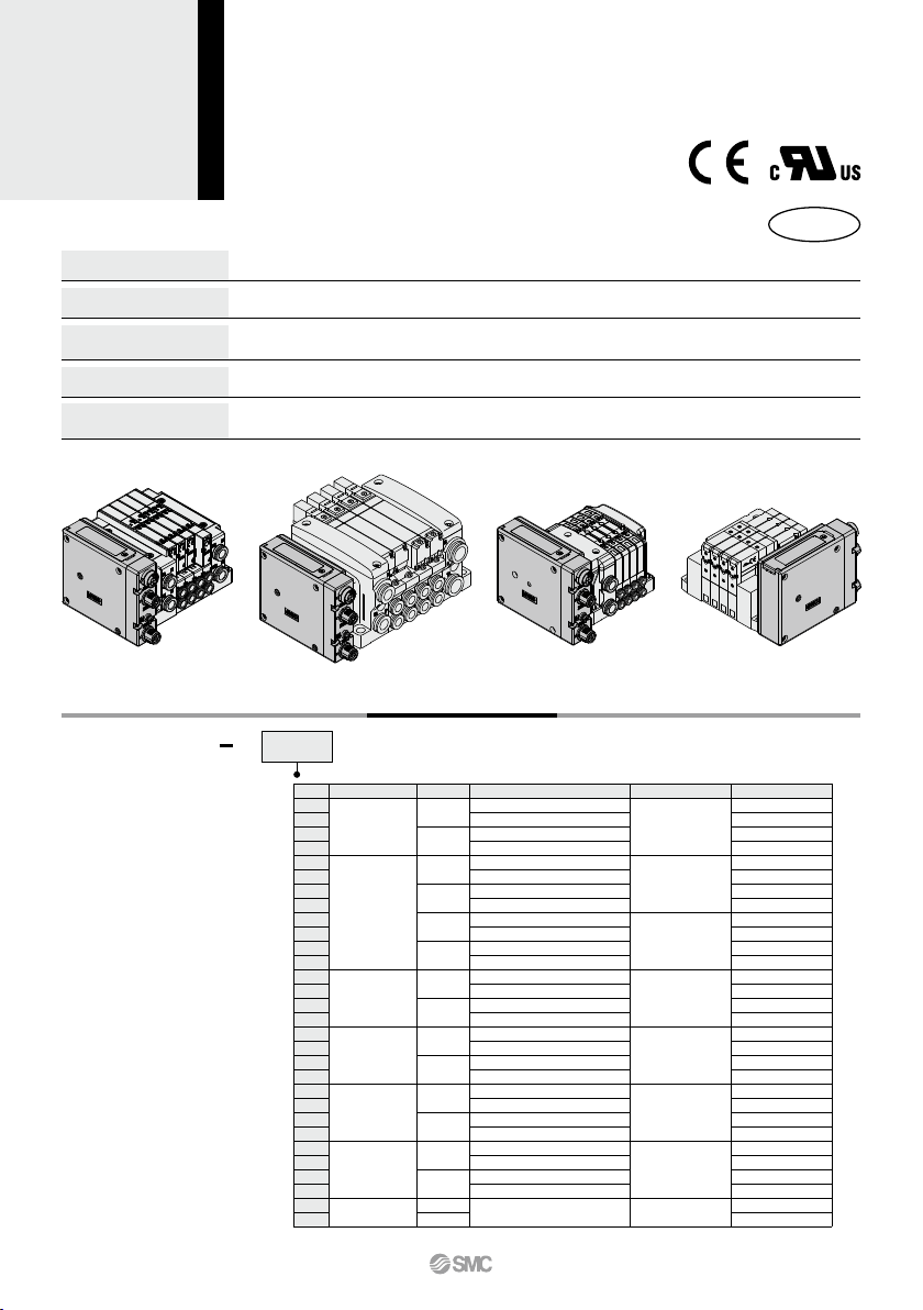
Communication protocol
Compact design
Compact design for space saving
Number of outputs
Each 32/16 digital output type available in the series
Enclosure
IP67 (For units with D-sub connector, and when connected with S0700 manifolds, it is IP40.)
Output polarity
Each negative common (PNP) / positive common (NPN) type available in the series
(SI Unit compatible with POWERLINK is only negative common (PNP) type.)
Internal terminating resistor
ON/OFF switching is possible with an internal terminating resistor for communication.
(Only for units compatible with M12 PROFIBUS DP, CC-Link communication connectors)
SY3000/5000/7000 VQC1000/2000/4000/5000 S0700 SV1000/2000/3000
D
D
D
D
How to Order SI Units
PR1
EX260 S
Note)
Note) The SY3000/5000/7000, VQC1000/2000/4000/5000, and S0700 are not yet UL-compatible.
CC-Link
®
RoHS
Protocol
Symbol
Number of outputs
Communication connector
Manifold symbol
EX260 Series
SI Unit/For Output
Note) Enclosure is IP40 when the communication connector is D-sub.
792
A
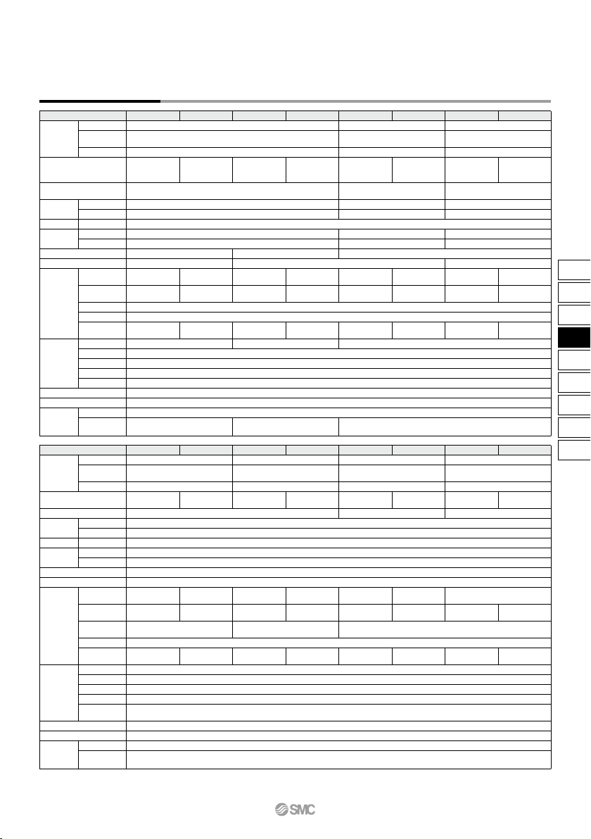
SI Unit Specifications
Model
EX260-SPR1/3 EX260-SPR2/4 EX260-SPR5/7 EX260-SPR6/8 EX260-SDN1/3 EX260-SDN2/4 EX260-SMJ1/3 EX260-SMJ2/4
125 k/250 k/500 kbps
156 k/625 k/
2.5 M/5 M/10 Mbps
M12
Built-in
—
—
22.8 to 26.4 VDC
11 to 25 VDC
100 mA or less
Applicable
system
I/O occupation area
(Inputs/Outputs)
Communication speed
Power supply
for control
Power supply for output
Communication connector specification
Terminating resistor switch
Power supply for
communication
Output
Environmental
resistance
Standards
Weight
Mounting screw
Accessories
IP67 IP40 IP67
–10 to 50°C
35 to 85%RH (No condensation)
500 VAC for 1 minute between terminals and housing
10 MΩ or more (500 VDC measured via megohmmeter) between terminals and housing
CE marking, UL (CSA) compatible
200 g
2 pcs.
24 VDC
Power supply voltage
Internal current consumption
Power supply voltage
Power supply voltage
Internal current consumption
Protocol
Version
Note 1)
Configuration file
Note 3)
Supplied current
Output type
Number of outputs
Load
Supplied voltage
Enclosure
Operating temperature range
Operating humidity range
Withstand voltage
Insulation resistance
Seal cap (for M12
connector socket)
Source/PNP
(Negative common)
Sink/NPN
(Positive common)
Source/PNP
(Negative common)
Sink/NPN
(Positive common)
Source/PNP
(Negative common)
Sink/NPN
(Positive common)
SPR1: 32 points
SPR3: 16 points
SPR2: 32 points
SPR4: 16 points
SPR5: 32 points
SPR7: 16 points
SPR6: 32 points
SPR8: 16 points
SDN1: 32 points
SDN3: 16 points
SDN2: 32 points
SDN4: 16 points
SPR1: 0/32
SPR3: 0/16
SPR2: 0/32
SPR4: 0/16
SPR5: 0/32
SPR7: 0/16
SPR6: 0/32
SPR8: 0/16
SDN1: 0/32
SDN3: 0/16
SDN2: 0/32
SDN4: 0/16
SMJ1: 32/32
SMJ3:
32/32
(1 station, remote I/O stations)
SMJ2: 32/32
SMJ4:
32/32
(1 station, remote I/O stations)
SPR1: Max. 2.0 A
SPR3: Max. 1.0 A
SPR2: Max. 2.0 A
SPR4: Max. 1.0 A
SPR5: Max. 2.0 A
SPR7: Max. 1.0 A
SPR6: Max. 2.0 A
SPR8: Max. 1.0 A
SDN1: Max. 2.0 A
SDN3: Max. 1.0 A
SDN2: Max. 2.0 A
SDN4: Max. 1.0 A
EX9-AWTS (1 pc.) — EX9-AWTS (1 pc.)
D-sub M12
None Built-in
Volume 1(Edition 3.5)
Volume 3(Edition 1.5)
9.6 k/19.2 k/45.45 k/93.75 k/
187.5 k/500 k/1.5 M/3 M/6 M/12 Mbps
21.6 to 26.4 VDC
100 mA or less
—
—
—
—
21.6 to 26.4 VDC
100 mA or less
PROFIBUS DP
DeviceNet™
CC-Link
DP-V0 Ver.1.10
—
GSD file EDS file
Source/PNP
(Negative common)
Sink/NPN
(Positive common)
SMJ1: 32 points
SMJ3: 16 points
SMJ2: 32 points
SMJ4: 16 points
SMJ1: Max. 2.0 A
SMJ3: Max. 1.0 A
SMJ2: Max. 2.0 A
SMJ4: Max. 1.0 A
Solenoid valve with protective circuit for surge voltage of 24 VDC/1.5 W or less (SMC)
Model
EX260-SEC1/3 EX260-SEC2/4 EX260-SPN1/3 EX260-SPN2/4 EX260-SEN1/3 EX260-SEN2/4
Applicable
system
I/O occupation area
(Inputs/Outputs)
Communication speed
Power supply
for control
Power supply for output
Communication connector specification
Terminating resistor switch
Power supply for
communication
Output
Environmental
resistance
Standards
Weight
Mounting screw
Accessories
IP67
–10 to 50°C
35 to 85%RH (No condensation)
500 VAC for 1 minute between terminals and housing
CE marking, UL (CSA) compatible
200 g
2 pcs.
10 MΩ or more (500 VDC measured via megohmmeter) between terminals and housing
24 VDC
Power supply voltage
Internal current consumption
Power supply voltage
Power supply voltage
Internal current consumption
Protocol
Version
Note 1)
Configuration file
Note 3)
Supplied voltage
Output type
Number of outputs
Load
Supplied voltage
Enclosure
Operating temperature range
Operating humidity range
Withstand voltage
Insulation
resistance
Seal cap (for M12
connector socket)
Source/PNP
(Negative common)
Sink/NPN
(Positive common)
Source/PNP
(Negative common)
Sink/NPN
(Positive common)
Source/PNP
(Negative common)
Sink/NPN
(Positive common)
SEC1: 32 points
SEC3: 16 points
SEC2: 32 points
SEC4: 16 points
SPN1: 32 points
SPN3: 16 points
SPN2: 32 points
SPN4: 16 points
SEN1: 32 points
SEN3: 16 points
SEN2: 32 points
SEN4: 16 points
SEC1: 0/32
SEC3: 0/16
SEC2: 0/32
SEC4: 0/16
SPN1: 0/32
SPN3: 0/16
SPN2: 0/32
SPN4: 0/16
SEN1: 16/32
SEN3: 16/16
SEN2: 16/32
SEN4: 16/16
SEC1: Max. 2.0 A
SEC3: Max. 1.0 A
SEC2: Max. 2.0 A
SEC4: Max. 1.0 A
SPN1: Max. 2.0 A
SPN3: Max. 1.0 A
SPN2: Max. 2.0 A
SPN4: Max. 1.0 A
SEN1: Max. 2.0 A
SEN3: Max. 1.0 A
SEN2: Max. 2.0 A
SEN4: Max. 1.0 A
EX9-AWTS (1 pc.)
Volume 1(Edition 3.8)
Volume 2(Edition 1.9)
21.6 to 26.4 VDC
100 mA or less
22.8 to 26.4 VDC
—
—
M12
None (Not required)
10 M/100 Mbps
Note 2)
100 Mbps
Note 2)
EtherCAT
Note 2)
EtherNet/IP™
Note 2)
Conformance
Test Record V.1.1
XML file
PROFINET
Note 2)
PROFINET Specification
Version 2.2
GSD file EDS file
Solenoid valve with protective circuit for surge
voltage of 24 VDC/1.5 W or less (SMC)
Solenoid valve with protective circuit for surge
voltage of 24 VDC/1.0 W or less (SMC)
Solenoid valve with protective circuit for surge
voltage of 24 VDC/1.5 W or less (SMC)
EX260-SPL1 EX260-SPL3
Source/PNP
(Negative common)
32 16
16/32 16/16
Max. 2 A Max. 1 A
EPSG DS 301 Version 1.2.0
100 Mbps
Note 2)
POWERLINK
XDD file
Note 1) Please note that the version is subject to change.
Note 2) Use a CAT5 or higher transmission cable for EtherCAT, PROFINET, EtherNet/IP™, POWERLINK.
Note 3) Each file can be downloaded from the SMC website, http://www.smcworld.com
For Output EX260 Series
793
EX12
EX140
EX180
EX260
EX250
EX600
EX500
EX510
PCA
EX
EX260
A
 Loading...