

Page 1
Summary of Product elements
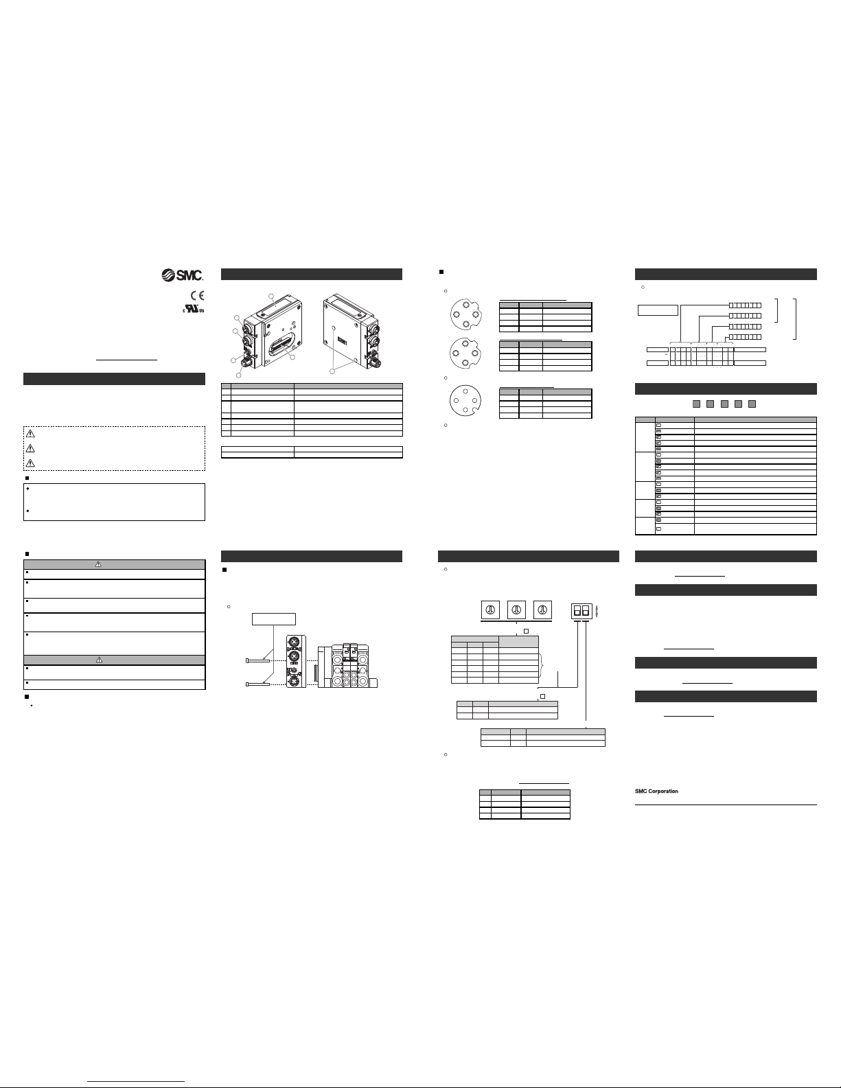
<EX260-SEN1/-SEN2/-SEN3/-SEN4>
1
3
4
5
2
6
Installation
7
General instructions on installation and maintenance
Connect valve manifold to the SI unit.
Connectable valve manifolds are the same as for EX250 series SI unit.
Refer to the EX250 series valve manifold section in the valve catalogue for valve
manifold dimensions.
1
2
3
4
1
2
3
4
P
ower supply connector layout
1
432
G
round terminal
C
onnect the ground terminal to ground.
R
esistance to ground should be 100 ohms or less.
Setting
M3 hexagon screw
Tightening torque 0.6 Nm
Valve manifold
∗: Thread size: M3 x 30
Replacement of the SI unit
•Remove the M3 hexagon screws from the SI unit and release the SI unit from the
valve manifold.
•Replace the SI unit.
•Tighten the screws with the specified tightening torque. (0.6 Nm)
Precautions for maintenance
•Be sure to switch off the power.
•Check there is no foreign matter inside the SI unit.
•Check there is no damage and no foreign matter on the gasket.
•Be sure to tighten the screws with the specified torque.
If the SI unit is not assembled properly, inside PCBs may be damaged or liquid and/or
dust may enter into the unit.
Connecting cables
S
elect the appropriate cables to mate with the connectors mounted on the SI unit.
Troubleshooting
Technical documentation giving detailed troubleshooting information can be found on the
SMC website (URL http://www.smcworld.com
).
Specifications
Connected load: 24 VDC Solenoid valve with surge voltage suppressor of 1.5 W or less
(manufactured by SMC)
Current consumption of power supply for SI unit operation: 0.1 A max.
Ambient temperature for operation: -10 to 50
o
C
Ambient temperature for storage: -20 to 60
o
C
Pollution degree 3: (UL508)
Technical documentation giving detailed specification information can be found on the SMC
website (URL http://www.smcworld.com
).
Outline Dimensions
Technical documentation giving detailed outline dimensions information can be found on
the SMC website (URL http://www.smcworld.com
).
Accessories
Technical documentation giving detailed accessories information can be found on the SMC
website (URL http://www.smcworld.com
).
Assembly and disassembly of the SI unit
NOTE
The direct current power supply to combine should be UL1310 Class2 power
supply when conformity to UL is necessary.
Safety Instructions
Do not operate the product outside of the specifications.
Do not use for flammable or harmful fluids.
Fire, malfunction, or damage to the product can result.
Verify the specifications before use.
Do not disassemble, modify (including changing the printed circuit board) or repair.
An injury or failure can result.
Do not operate in an atmosphere containing flammable or explosive gases.
Fire or an explosion can result.
This product is not designed to be explosion proof.
If using the product in an interlocking circuit:
•
Provide a double interlocking system, for example a mechanical system.
•Check the product regularly for proper operation.
Otherwise malfunction can result, causing an accident.
The following instructions must be followed during maintenance:
•Turn off the power supply.
•Stop the air supply, exhaust the residual pressure and verify that the air is released before performing
maintenance.
Otherwise an injury can result.
Fieldbus device
Operation Manual
EX260 Series for EtherNet/IP
TM
T
hank you for purchasing an SMC EX260 Series Fieldbus device (Hereinafter
referred to as "SI unit" ).
Please read this manual carefully before operating the product and make sure you
u
nderstand its capabilities and limitations.
Please keep this manual handy for future reference.
T
o obtain more detailed information about operating this product, please
refer to the SMC website (URL http://www.smcworld.com
) or contact SMC
directly.
Safety Instructions
These safety instructions are intended to prevent hazardous situations and/or
equipment damage.
These instructions indicate the level of potential hazard with the labels of
"Caution", "Warning" or "Danger". They are all important notes for safety and must
be followed in addition to International standards (ISO/IEC) and other safety
regulations.
Warning
Caution
After maintenance is complete, perform appropriate functional inspections.
Stop operation if the equipment does not function properly.
Safety cannot be assured in the case of unexpected malfunction.
C
AUTION indicates a hazard with a low level of risk which, if
not avoided, could result in minor or moderate injury.
Caution:
Warning:
Danger:
W
ARNING indicates a hazard with a medium level of risk
which, if not avoided, could result in death or serious injury.
D
ANGER indicates a hazard with a high level of risk which, if
n
ot avoided, will result in death or serious injury.
Fieldbus interface connector (BUS OUT)
E
lement
D
escription
EtherNet/IPTMconnection PORT 2 (M12 4-pin socket, D-coded)
F
ieldbus interface connector (BUS IN)EtherNet/IP
T
M
c
onnection PORT 1 (M12 4-pin socket, D-coded)
G
round terminal
F
unctional earth (M3 screw)
Output connector Output signal interface for valve manifold
1
N
o.
2
4
5
2
pcs. M3 x 30 screw for connection to the valve manifold
Seal cap
1 pc. seal cap for unused fieldbus interface connector (BUS OUT)
Accessories
L
ED
B
us status−specific and SI unit−specific LEDs
Mounting hole Mounting hole for connection to the valve manifold
6
7
Power supply connector
P
ower supply with load voltage for valves and operating voltage for SI unit
(M12 4-pin plug, A-coded)
3
H
exagon socket head cap screw
BUS OUT: M12 4-pin socket D-coded
TD+
Designation Description
Transmit Data +
RD+ Receive Data +
TD- Transmit Data -
1
N
o.
2
3
RD-R
eceive Data -
4
BUS IN: M12 4-pin socket D-coded
TD+
D
esignationDescription
Transmit Data +
RD+ Receive Data +
TD- Transmit Data -
1
No.
2
3
RD- Receive Data -4
PWR: M12 4-pin plug A-coded
S
I24 V
Designation Description
+
24 V for SI unit operation
S
V24 V+24 V for solenoid valve
SI0 V 0 V for SI unit operation
1
No.
2
3
SV0 V 0 V for solenoid valve4
Note: Specifications are subject to change without prior notice and any obligation on the part of the manufacturer.
EtherNet/IPTMis a trademark of ODVA.
© 2012 SMC Corporation All Rights Reserved
Akihabara UDX 15F, 4-14-1, Sotokanda, Chiyoda-ku, Tokyo 101-0021, JAPAN
Phone: +81 3-5207-8249 Fax: +81 3-5298-5362
URL http://www.smcworld.com
Provide grounding to assure the safety and noise resistance of the Serial system.
Individual grounding should be provided close to the product with a short cable.
LED indication
F
ieldbus interface connector layout
Switch setting
The switches should only be set with the power supply turned off.
Open the cover and set the rotary switches and DIP switch with a small flat blade
screwdriver.
Operator
This operation manual is intended for those who have knowledge of machinery
using pneumatic equipment, and have sufficient knowledge of assembly,
operation and maintenance of such equipment. Only those persons are
allowed to perform assembly, operation and maintenance.
Read and understand this operation manual carefully before assembling,
operating or providing maintenance to the product.
Configuration
In order to configure the SI unit for the EtherNet/IP
TM
network, the appropriate device
master file (EDS file) for the SI unit will be required.
Technical documentation giving detailed configuration information and the EDS file can
be found on the SMC website (URL http://www.smcworld.com
).
Setting
Bit: 70
Bit: 7
0
Bit: 70
Bit: 70
012
46
357
891
6
17
3
0
31
2
8
29
64
64
1
3571 1 57
Output No.
Output No.
B
it No.
B
it No.
Valve manifold
Solenoid on side A
Solenoid on side B
Side D
0: Solenoid valve: OFF
1: Solenoid valve: ON
Byte
0 Offset
Byte
1 Offset
Byte
2 Offset
Byte
3 Offset
(SI unit side)
2000
16 outputs
t
ype
3
2 outputs
type
EX260-SEN1
Model number EDS file
ex260_sen1_24_v∗∗.eds
EX260-SEN2
1
2
EDS file
O
utput number assignment
O
utput numbering starts at zero and refers to the solenoid position on the manifold.
x100
IP address x
×10 ×1
0
5
2
7
8
3
9
4
1
6
0
5
2
7
8
3
9
4
1
6
0
5
2
7
8
3
9
4
1
6
12
DIP SW
∗: The values of 256 or more are not used.
0
0
0
Setting
2
:
1
Remote control
X
:
254
DHCP mode
1
2
0
:
554
5
01OFF
ON
The IP address is set to “192.168.0.X.
The IP address is set to “192.168.1.X.
Y No.1 Description
CLEAR
HOLD
OFFONClear all outputs.
Hold the last state before communication error.
HOLD/CLEAR No.2 Description
×10
0
0
0
:
2
2
×100 ×1
ON
OFF
Manual set up
of IP address
IP address
192.168. Y . X
IP address
192.168. Y . X
HOLD/CLEAR setting
MSNS
L/A1 L/A2
PWR(V)
N
S
LED LED Status
OFF
G
reen flashing
TheSI unit operating voltage is not supplied or the IP address is not set.
EtherNet/IPTMcommunications not established.
MS
O
FF
G
reen ON
TheSI unit operating valtage is not supplied.
Operatingnormally.
Red ON
Unrecoverableerror.
L
/A1
OFF
G
reen ON
BUS IN side: No Link, No Activity
B
US IN side: Link, No Activity
PWR(V)
Green ON
OFF
Load voltage for the valve is supplied
Load voltage for the valve is not supplied or is outside the tolerance range
(
19 V or less)
Description
L/A2
O
FF
Green ON
B
US OUT side: No Link, No Activity
BUS OUT side: Link, No Activity
Green flashing
BUS IN side: Link, Activity
Green flashing
Settingerror.
Red flashing
Recoverableerror.
Green flashing
BUS OUT side: Link, Activity
Green ON
EtherNet/IPTMcommunications established.
Red flashing
EtherNet/IP
T
M
communications time out.
R
ed ON
IPaddress duplicated.
ex260_sen2_24_v**.eds
EX260-SEN3 ex260_sen3_22_v**.eds
EX260-SEN4
3
4
ex260_sen4_22_v**.eds
 Loading...