

Page 1
Summary of Product element
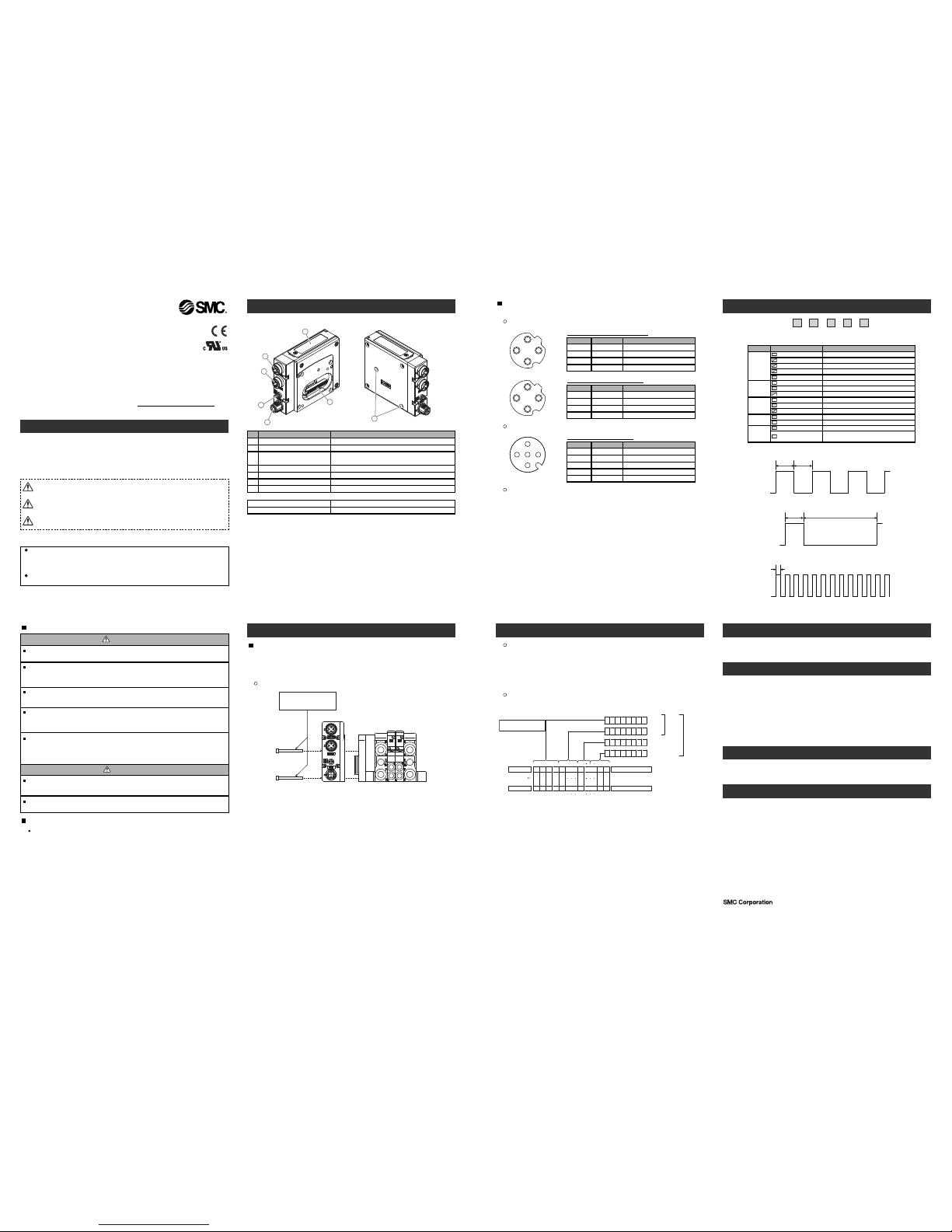
<EX260-SEC1/-SEC2/-SEC3/-SEC4>
1
3
4
5
2
6
Installation
Configuration
Auto-increment addressing can be used to address each slave device via its physical
position in the communication ring, and not require local address setting.
To configure the EX260 SI unit with the EtherCAT master, XML Device Description File
is required.
The technical document states detail configuration information and the XML file can be
found on the SMC website (http://www.smcworld.com.)
Output number assignment
Output number starts at zero and refers to the solenoid position on the manifold.
7
General instructions on installation and maintenance
Connect valve manifold to the SI unit.
Connectable valve manifolds are same as for EX250 series SI unit.
Refer to the EX250 series valve manifold section in the valve catalogue for valve
manifold dimension.
1
2
3
4
1
2
3
4
P
ower supply connector layout
1
4
5
3
2
Ground terminal
Connect the ground terminal to the ground.
R
esistance to ground should be 100 ohms or less.
Setting
M3 hexagon screw
Tightening torque 0.6 Nm
Valve manifold
*: Thread size: M3×30
Replacement of the SI unit
•Remove the M3 hexagon screw from the SI unit and release the SI unit from the
valve manifold.
•Replace the SI unit.
•Tighten the screws with the specified tightening torque. (0.6 Nm)
Precautions for maintenance
•Be sure to switch off the power.
•Check there is no foreign matter inside the SI unit.
•Check there is no damage and no foreign matter being stuck to the gasket.
•Be sure to tighten the screw with the specified torque.
If the SI unit is not assembled properly, inside PCBs may be damaged or liquid and/or
dust may enter into the unit.
Connecting cables
S
elect the appropriate cables to fit with the connectors mounted on the SI unit.
F
ieldbus interface connector layout
Troubleshooting
The technical document states detail troubleshooting information can be found on
the SMC website (URL http://www.smcworld.com)
Specifications
Connected load: 24 VDC Solenoid valve with light and surge voltage suppressor of 1.5 W
or less (manufactured by SMC)
Current consumption of power supply for SI unit operation: 0.1 A max.
Ambient temperature for operation: -10 to 50 ℃
Ambient temperature for storage: -20 to 60 ℃
Pollution degree 2: (UL508)
The technical document states detail specification information can be found on the
SMC website (URL http://www.smcworld.com)
Akihabara UDX 15F, 4-14-1, Sotokanda, Chiyoda-ku, Tokyo 101-0021, JAPAN
Phone: +81 3-5207-8249 Fax: +81 3-5298-5362
URL http://www.smcworld.com
Outline Dimensions
The technical document states detail outline dimensions information can be found
on the SMC website (URL http://www.smcworld.com)
Accessories
The technical document states detail accessories information can be found on the
SMC website (URL http://www.smcworld.com)
Bit: 7 0
Bit: 7
0
Bit: 7
0
Bit: 7
0
01246
35789161730312829
64 64
13571 1 57
Output No.
Output No.
Bit No.
Bit No.
Valve manifold
Solenoid on side A
Solenoid on side B
Side D
0: Solenoid valve: OFF
1: Solenoid valve: ON
Byte
0 Offset
Byte
1 Offset
Byte
2 Offset
Byte
3 Offset
(SI unit side)
200
0
16 outputs
type
32 outputs
type
RUNL
/A IN L/A OUTPWR(V)PWR
RUN
LED Status
OFF
Green blinking
※1
G
reen single flash
※2
Green flickering
※3
Green ON
INIT
P
RE-OPERATIONAL
SAFE-OPERATIONAL
BOOTSTRAP
OPERATIONAL
L
/A IN
OFF
Green ON
Green flickering
※3
BUS IN side: No Link, No Activity
B
US IN side: Link, No Activity
BUS IN side: Link, Activity
L
/A OUT
O
FF
Green ON
Green flickering
※3
BUS OUT side: No Link, No Activity
BUS OUT side: Link, No Activity
B
US OUT side: Link, Activity
P
WR(V)
Green ON
OFF
Load voltage for the valve is supplied
Load voltage for the valve is not supplied or
o
utside tolerance range (19 V or less)
PWR
Green ON
OFF
SI unit operating voltage is supplied
SI unit operating voltage is not supplied
50 ms
ON
OFF
*2: Single flash pattern
*1: Blinking pattern
200 ms 200 ms
O
N
OFF
2
00 ms 1000 ms
ON
OFF
Assembly and disassembly of the SI unit
*3: Flickering pattern
LED indication
NOTE
When conformity to UL is necessary the SI unit must be used with a UL 1310
Class2 power supply.
Safety Instructions
Do not operate the product outside of the specifications.
Do not use for flammable or harmful fluids.
F
ire, malfunction, or damage to the product can result.
V
erify the specifications before use.
Do not disassemble, modify (including changing the printed circuit board) or repair.
An injury or failure can result.
Do not operate in an atmosphere containing flammable or explosive gases.
Fire or an explosion can result.
This product is not designed to be explosion proof.
If using the product in an interlocking circuit:
•Provide a double interlocking system, for example a mechanical system.
•Check the product regularly for proper operation.
Otherwise malfunction can result, causing an accident.
The following instructions must be followed during maintenance:
•Turn off the power supply.
•Stop the air supply, exhaust the residual pressure and verify that the air is released before performing maintenance.
Otherwise an injury can result.
Provide grounding to assure the safety and noise resistance of the Fieldbus system.
Individual grounding should be provided close to the product with a short cable.
Fieldbus device
Operation Manual
EX260 Series for EtherCAT
T
hank you for purchasing an SMC EX260 Series Fieldbus device (Hereinafter
referred to as "SI unit" ).
Please read this manual carefully before operating the product and make sure you
u
nderstand its capabilities and limitations.
Please keep this manual handy for future reference.
To obtain more detailed information about operating this product,
p
lease refer to the SMC website (URL http://www.smcworld.com
)
or
contact SMC directly.
Safety Instructions
T
hese safety instructions are intended to prevent hazardous situations and/or
equipment damage.
These instructions indicate the level of potential hazard with the labels of
"Caution", " Warning" or "Danger". They are all important notes for safety and
must be followed in addition to International standards (ISO/IEC), Japan Industrial
Standards (JIS) and other safety regulations.
Warning
Caution
After maintenance is complete, perform appropriate functional inspections.
Stop operation if the equipment does not function properly.
Safety cannot be assured in the case of unexpected malfunction.
C
AUTION indicates a hazard with a low level of risk which, if
not avoided, could result in minor or moderate injury.
Caution:
Warning:
Danger:
WARNING indicates a hazard with a medium level of risk
w
hich, if not avoided, could result in death or serious injury.
DANGER indicates a hazard with a high level of risk which, if
n
ot avoided, will result in death or serious injury.
Operator
This operation manual is intended for those who have knowledge of machinery
using pneumatic equipment, and have sufficient knowledge of assembly,
operation and maintenace of such equipment. Only those persons are allowed
to perform assembly, operation and maintenance.
Read and understand this operation manual carefully before assembling,
operating or providing maintenance to the product.
Note: Specifications are subject to change without prior notice and any obligation on the part of the manufacturer.
EtherCAT
®
is registered trademark and patented technology, licensed by Beckhoff Automation GmbH, Germany.
© 2010 SMC Corporation All Rights Reserved
Fieldbus interface connector (BUS OUT)
E
lement
D
escription
EtherCAT connection (M12 4-pole socket, D-coded)
Fieldbus interface connector (BUS IN) EtherCAT connection (M12 4-pole socket, D-coded)
G
round terminal
F
unctional earth (M3 screw)
Output connector Output signal interface for valve manifold
1
N
o.
2
4
5
2pcs. M3x30 screw for connection to the valve manifold
Seal cap 1
pc. seal cap for unused fieldbus interface connector (BUS OUT)
Accessories
L
ED
B
us status−specific and SI unit−specific LEDs
Mounting hole
Mounting hole for connection to the valve manifold
6
7
Power supply connector
P
ower supply with load voltage for valves and operating voltage for SI unit
(M12 5-pole plug, A-coded)
3
Hexagon socket head cap screw
BUS OUT: M12 4-pole Socket D-coded
TD+
Designation Description
Transmission Data +
RD+R
eceiving Data +
TD- Transmission Data -
1
No.
2
3
RD- Receiving Data -4
BUS IN: M12 4-pole Socket D-coded
TD+
Designation Description
Transmission Data +
RD+ Receiving Data +
TD- Transmission Data -
1
No.
2
3
RD- Receiving Data -4
PWR: M12 5-pole Plug A-coded
S
V24 V
D
esignation
D
escription
+
24 V for solenoid valve
SV0 V 0 V for solenoid valve
S
I24 V+24 V for SI unit operation
1
N
o.
2
3
SI0 V 0 V for SI unit operation4
- U
nused
5
Description
 Loading...