

SMC Networks EX260-SDN1, EX260-SDN2, EX260-SDN3, EX260-SDN4 Installation & Maintenance Manual
Installation & Maintenance Manual
Fieldbus device (SI unit)
EX260 Series for DeviceNet
T
M
E
X260-TFN21
Safety Instructions
This manual contains essential information for the protection of users
and others from possible injury and/or equipment damage.
•Read this manual before using the product, to ensure correct handling,
and read the manuals of related apparatus before use.
•Keep this manual in a safe place for future reference.
•These instructions indicate the level of potential hazard with the labels
of "Caution", "Warning" or "Danger", followed by important safety
information which must be carefully followed.
•To ensure safety of personnel and equipment the safety instructions in
this manual and the product catalogue must be observed, along with
other relevant safety practices.
WARNING indicates a hazard with a medium level
of risk which, if not avoided, could result in death or
serious injury.
DANGER indicates a hazard with a high level of risk
which, if not avoided, will result in death or serious
injury.
CAUTION indicates a hazard with a low level of risk
which, if not avoided, could result in minor or
moderate injury.
Caution
Warning
Danger
S
ummary of Product element
This product is class A equipment that is intended for use in an industrial
environment.
There may be potential difficulties in ensuring electromagnetic
compatibility in other environments due to conducted as well as radiated
disturbances.
NOTE
•When conformity to UL is necessary the SI unit must be used with a
UL 1310 Class2 power supply.
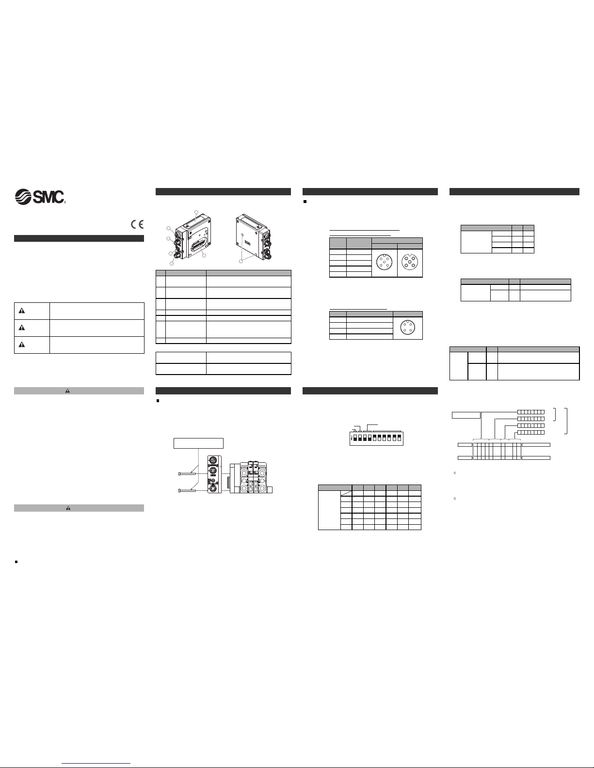
<EX260-SDN1/-SDN2/-SDN3/-SDN4>
1
3
4
2
5
6
7
Fieldbus interface
connector (BUS OUT)
Element Description
DeviceNetTMconnection
(M12 5-pole socket, A-coded)
Fieldbus interface
connector (BUS IN)
DeviceNetTMconnection
(M12 5-pole plug, A-coded)
Ground terminal Functional earth (M3 screw)
Output connector Output signal interface for valve manifold
1
No.
2
4
5
2 pcs. M3x30 screw for connection to the valve
manifold
Seal cap
1 pc. seal cap for unused fieldbus interface
connector (BUS OUT)
Accessories
LED and switch
Bus status−specific and SI unit−specific LEDs
Switches for setting of node address and
operating mode
Mounting hole
Mounting hole for connection to the valve manifold
6
7
Power supply
connector
Power supply with load voltage for valves
(M12 4-pole plug, A-coded)
3
Hexagon socket head cap
screw
•Do not disassemble, modify (including changing the printed circuit
board) or repair.
An injury or failure can result.
•Do not operate the product outside of the specifications.
Do not use for flammable or harmful fluids.
Fire, malfunction, or damage to the product can result.
Verify the specifications before use.
•Do not operate in an atmosphere containing flammable or
explosive gases.
Fire or an explosion can result.
This product is not designed to be explosion proof.
•If using the product in an interlocking circuit:
•Provide a double interlocking system, for example a mechanical
system.
•Check the product regularly for proper operation.
Otherwise malfunction can result, causing an accident.
•The following instructions must be followed during maintenance:
•Turn off the power supply.
•Stop the air supply, exhaust the residual pressure and verify that the
air is released before performing maintenance.
Otherwise an injury can result.
•After maintenance is complete, perform appropriate functional
inspections.
Stop operation if the equipment does not function properly.
Safety cannot be assured in the case of unexpected malfunction.
•Provide grounding to assure the safety and noise resistance of the
Fieldbus system.
Individual grounding should be provided close to the product with a
short cable.
Installation
General instructions on installation and maintenance
Connect valve manifold to the SI unit.
Connectable valve manifolds are the same as for EX250 series SI unit.
Refer to the EX250 series valve manifold section in the valve catalogue
for valve manifold dimensions.
M3 hexagon screw
Tightening torque 0.6 Nm
Valve manifold
∗: Thread size: M3×30
Replacement of the SI unit
•Remove the M3 hexagon screws from the SI unit and release the
SI unit from the valve manifold.
•Replace the SI unit.
•Tighten the screws with the specified tightening torque. (0.6 Nm)
Precautions for maintenance
•Be sure to switch off the power.
•Check there is no foreign matter inside the SI unit.
•Check there is no damage and no foreign matter being stuck to the
gasket.
•Be sure to tighten the screws with the specified torque.
If the SI unit is not assembled properly, inside PCBs may be damaged or
liquid and/or dust may enter into the unit.
Assembly and disassembly of the SI unit
I
nstallation (Continued)
Connecting cables
Select the appropriate cables to mate with the connectors mounted on the
SI unit.
Fieldbus interface connector layout
Warning
Caution
BUS OUT: M12 5-pole socket A-coded
DRAIN
Designation
Contact layout
BUS IN
V+
V-
CAN_L
1
No.
2
3
5
CAN_H4
2
5
43
1
1
5
4
3
2
BUS OUT
BUS IN: M12
5-pole plug A-coded
Note: To avoid causing disruption of “downstream” devices whilst
replacing SI unit, use a DeviceNetTMtap rather than making
connections to the BUS OUT connector.
Power supply connector layout
Ground terminal
Connect the ground terminal to ground.
Resistance to ground should be 100 ohms or less.
−
Designation
Contact layout
+24 V for solenoid valve
−
1
No.
2
3
0 V for solenoid valve4
1
3
4
2
PWR: M12 4-pole plug A-coded
Switch setting
Set the DeviceNet
TM
node address (MAC ID), DeviceNetTMcommunication
speed and fail safe mode of the SI unit using the 10-element switch.
Communication speed
Address
HW/SW
HOLD/CLEAR
9 107 85 63 41 2
ON
Setting
Note: Be sure to switch off the power supply before setting the switches.
MAC ID
Switch No. No.6No.5 No.8No.7 No.10No.9
Address setting (switch No. 5 to 10)
The DeviceNet
TM
address (MAC ID) is binary coded and can be set from
0 to 63
Note: Factory default setting is 63.
1632 4
8
12
00 00 000
00 00 101
00 00 012
:: :: :::
11 11 0162
11 11 1163
0: OFF, 1: ON
S
etting (Continued)
Communication speed setting (switch No. 3 to 4)
The DeviceNetTMcommunication speed is binary coded and can be
set to 125 kbps, 250 kbps and 500 kbps.
N
ote: Factory default setting is 125 kbps.
Communication
speed
Switch No. No.4No.3
00
10250 kbps
01500 kbps
11
-
0: OFF, 1: ON
125 kbps
Note: Each output can be set individually over the network.
HOLD/CLEAR setting (switch No.2)
Set the reaction of outputs to the communication error
(All outputs will be set under the same conditions)
N
ote: Factory default setting is CLEAR.
HOLD/CLEAR
Switch No. DescriptionNo.2
0
Hold the last state before
communication error
1
HOLD
CLEAR
Clear all outputs
0: OFF, 1: ON
HW/SW mode setting (switch No.1)
Modifications to the address and speed can be made locally or over
the network.
Local setting: Hardware mode (Hereinafter referred to as “HW mode”)
Network setting: Software mode (Hereinafter referred to as “SW mode”)
Note: Factory default setting is "HW mode".
HW/SW
Switch No. DescriptionNo.1
0
Set the address and speed over the
DeviceNetTMnetwork
(Switch setting is invalid)
1SW
HW
Set the address and speed locally using the
SI unit switches
0: OFF, 1: ON
Output number assignment
The output number refers to the solenoid position on the manifold and
starts at zero.
Bit: 7 0
Bit: 7
0
Bit: 7
0
Bit: 7
0
01246
35789161730312829
64
・・・・・・
・・・
・・・
・・・
・・・
64
13571 1 57
Output No.
Output No.
Bit No.
Bit No.
→
Valve manifold
Solenoid on side A
Solenoid on side B
Side D
0
: Solenoid valve: OFF
1: Solenoid valve: ON
Byte
0 Offset
Byte
1 Offset
Byte
2 Offset
Byte
3 Offset
(SI unit side)
200
0
16 outputs
t
ype
32 outputs
type
Setting over the DeviceNetTMnetwork
Technical documentation giving detailed information about setting
the unit over the DeviceNetTMnetwork can be found on the SMC
website (URL http://www.smcworld.com)
Diagnostic information
Technical documentation giving detailed diagnostic information can
be found on the SMC website (URL http://www.smcworld.com)
E
X260-TFN21
Contacts
AUSTRIA (43) 2262 62280 NETHERLANDS (31) 20 531 8888
BELGIUM (32) 3 355 1464 NORWAY (47) 67 12 90 20
CZECH REP. (420) 541 424 611 POLAND (48) 22 211 9600
DENMARK (45) 7025 2900 PORTUGAL (351) 21 471 1880
FINLAND (358) 207 513513 SLOVAKIA (421) 2 444 56725
FRANCE (33) 1 6476 1000 SLOVENIA (386) 73 885 412
GERMANY (49) 6103 4020 SPAIN (34) 945 184 100
GREECE (30) 210 271 7265 SWEDEN (46) 8 603 1200
HUNGARY (36) 23 511 390 SWITZERLAND (41) 52 396 3131
IRELAND (353) 1 403 9000 UNITED KINGDOM (44) 1908 563888
ITALY (39) 02 92711
URL http://www.smcworld.com (Global) http://www.smceu.com (Europe)
Specifications are subject to change without prior notice from the manufacturer.
© 2010 SMC Corporation All Rights Reserved.
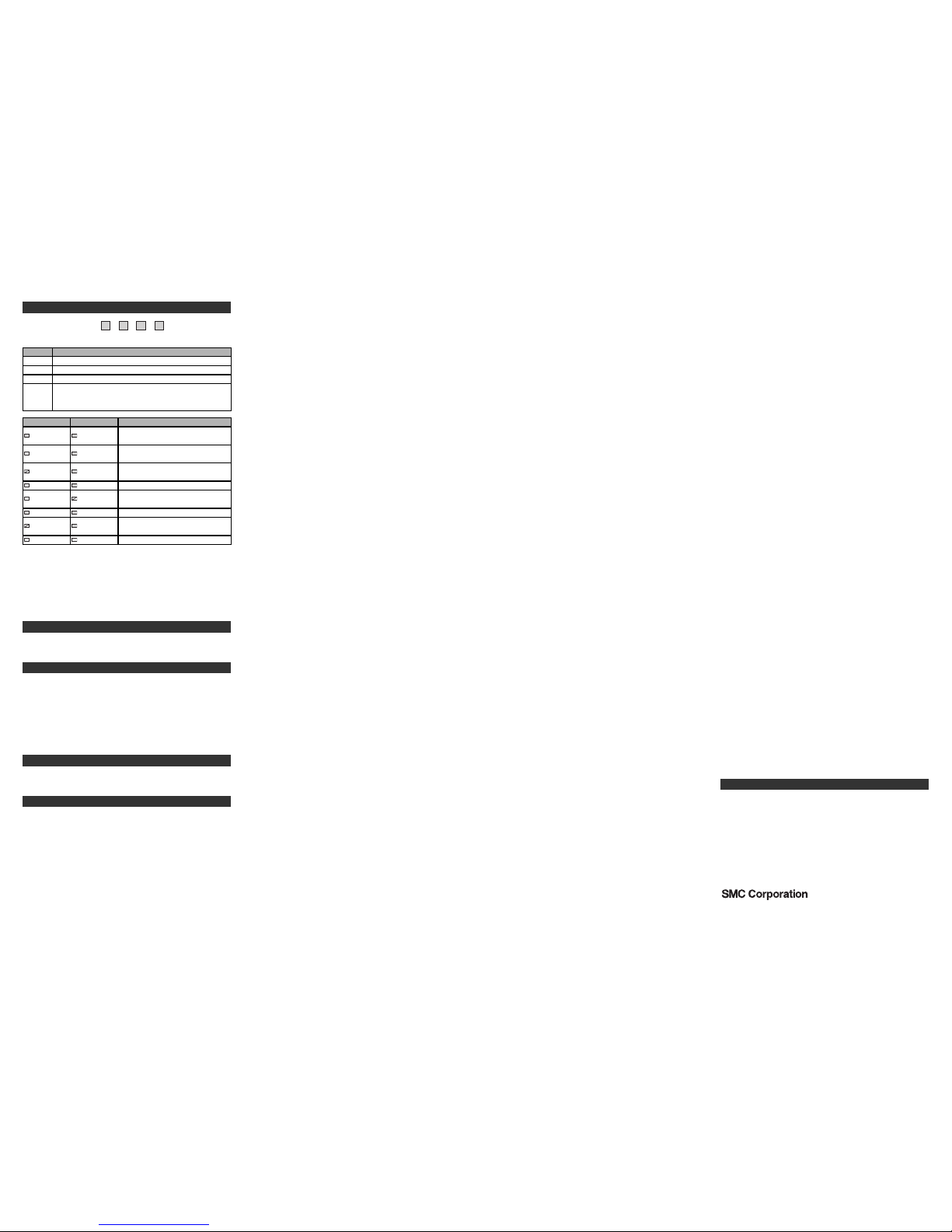
L
ED indication
N
S
M
S PWR PWR(V)
PWR (V)
LED Description
Turns ON in green when load voltage for the valve is supplied
Turns OFF when load voltage for the valve is not supplied or
outside tolerance range (19 V or less)
PWR Turns ON in green when network power is supplied
NS Network status (See the table below for details)
MS SI unit status (See the table below for details)
Green On
MS status
Description
On-line state, The device has
connections in the established state
Green On
Off-line state, The device has not
completed the Dup_MAC_ID test yet
Green On
On-line state, The device has no
connections in the established state
Green On
NS status
Off
Green flashing
Red On Off-line state, Watchdog timer error
Red flashing
Wrong switch setting, Parameter
writing error
Green On Bus-off state, Duplicate MAC ID
Off
Off
Red On
Green On
I/O Connection is in the Timed-Out
state
Off No network power present
Red flashing
Off
Troubleshooting
Technical documentation giving detailed troubleshooting information can
be found on the SMC website (URL http://www.smcworld.com).
Specifications
Connected load: 24 VDC Solenoid valve with light and surge voltage
suppressor of 1.5 W or less (manufactured by SMC)
Current consumption of power supply for SI unit operation: 0.1 A max.
Ambient temperature for operation: -10 to 50 ℃
Ambient temperature for storage: -20 to 60 ℃
Pollution degree 2: (UL508)
Technical documentation giving detailed specifications can be found on
the SMC website (URL http://www.smcworld.com).
Technical documentation giving detailed outline dimensions can be
found on the SMC website (URL http://www.smcworld.com).
Technical documentation giving detailed accessories information can be
found on the SMC website (URL http://www.smcworld.com).
Outline Dimensions
Accessories
 Loading...