

SMC Networks EX250-SMJ2 Installation & Maintenance Manual
Installation & Maintenance Manual
SI unit - CC-Link compatible
Type EX250-SMJ2
The unit and this manual contain essential information to protect
users and others from possible injury and property damage and to
ensure correct handling.
P
lease confirm that you fully understand the meaning of the
following messages (signs) before reading the text, and always
follow the instructions.
Please read the Installation & Maintenance Manual for related
apparatus and understand it before operating the actuator.
Read this manual and follow the instructions.
Signal words such as WARNING, CAUTION and NOTE, will be
followed by important safety information that must be reviewed
carefully.
IMPORTANT MESSAGES
Indicates a potentially hazardous situation
which could result in death or serious
injury if you do not follow instructions.
Provides you helpful information.
Do not disassemble, modify (including change of printed
circuit board) or repair.
An injury or failure can result.
Do not operate outside of the specification range.
Fire, malfunction or damage can result.
Please use it after confirming the specification.
Do not use the product in environments with possible
presence of flammable, explosive or corrosion gas.
Otherwise fire, explosion or corrosion can result.
The product is not designed to be explosion proof.
• Connect wires and cables correctly.
• Do not connect wires while the power is on.
• Do not lay wires or cables with the same wiring route as a power line
or high-voltage line.
• Verify the insulation of the wiring.
• Take proper measures against noise such as a noise filter when the
product is incorporated in equipment or devices.
• Select an operation environment according to enclosure(IP67).
• Take sufficient shielding measures when installing the product at the
following place.
(1)A place where a noise due to static electricity etc. is generated
(2)A place of high electric field strength
(3)A place possibly exposed to radioactivity
(4)A place near power cable
• Do not use the product nearby a place where an electric surge is
generated.
• Use the product equipped with a surge absorber when a surgegenerating load such as a solenoid valve is driven directly.
• Prevent foreign matter such as remnant of wires from entering the
product.
• Do not expose the product to vibration and impact.
• Keep the specified ambient temperature range (+5 to +45
o
C).
• Do not expose the product to heat radiation from a heat source
located nearby.
• Use a precision screw driver with small flat blade when setting rotary
switch and DIP switch.
• Perform maintenance and check at regular intervals.
• Perform a proper functional check.
• Do not clean the product with chemicals such as benzine and thinner.
Safety Instructions
Indicates a potentially hazardous situation
which if not avoided, may result in minor
injury or moderate injury.
Do not apply voltages exceeding 250V between a lead
wire and a metal fitting.
Pay attention to perform an insulation test because it could damage
the insulation of the lead wire and cause failure.
These instructions must be followed when using the
product in an interlocking circuit:
• Provide double interlocking through another system
such as mechanical protection.
• Check the product regularly to ensure proper operation.
Otherwise malfunction can cause an accident.
These instructions must be followed when performing
maintenance work:
• Turn off the power supply
• Stop the air supply, exhaust the residual pressure and
verify that the air is released before performing
maintenance work.
Otherwise it can cause injury.
Perform a proper functional check after completing
maintenance work.
Stop operation when an abnormality is observed or the product is not
working properly.
Safety cannot be assured due to unexpected malfunctions.
NOTE
The direct-current power supply should be a UL authorized power
supply.
1.Limited voltage current circuit in accordance with UL508
A circuit to which power is supplied by the secondary coil of a
transformer that meets the following conditions.
• Max. voltage(with no load): less than 30Vrms (42.4V peak)
• Max. current: (1)less than 8A(including when short circuited)
(2)limited by circuit protector (such as fuse) with the
following ratings
2.UL1310 compatible class 2 power supply unit or circuit of max.
30Vrms (42.4V peak) or less using a UL1585 compatible class 2
transformer as power supply. (Class 2 circuit)
Follow the instructions given below when handling the product.
Failure to follow instructions may damage the unit.
• Operate the product within the specified voltage range.
• Reserve a space around the unit for maintenance.
• Do not remove labels.
• Do not drop, hit or apply excessive shock to the product.
• Do not bend or apply tensile force to cables, or apply a force by
placing a heavy load on them.
No load voltage (V peak)
0 to 20 [V]
20 to 30 [V]
Max.current rating (A)
5.0
100 / peak voltage
Specification
Item Specification
Operating ambient temp. +5 to +45 oC
Operating ambient humidity 35 to 85% RH (No dew condensation)
Storage ambient temp. -20 to +60 oC
Vibration proof
10 to 57Hz 0.35mm (Constant amplitude)
57 to 150Hz 50m/s2(Constant acceleration)
Impact proof
150m/s2(peak), 11ms three times in each
direction ± X, Y and Z
Noise immunity
Normal mode : ±1500V Pulse duration 1us
Common mode : ±1500V Pulse duration 1us
Radiation : ±1000V Pulse duration 1us
Withstand voltage 500V AC for 1min.
Insulation resistance 500V DC min10M ohm
Operating environment No corrosive gas and no dust
General specification
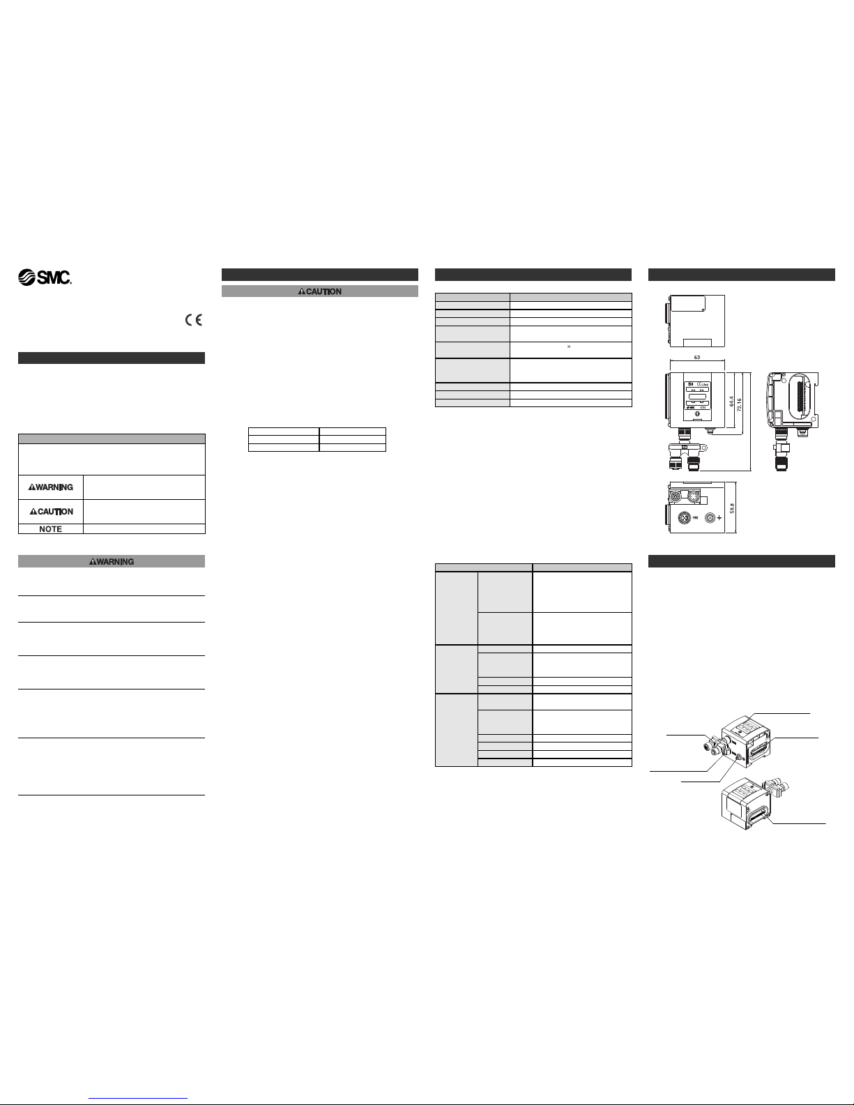
Outline with Dimensions (in mm)
Item Specification
Power voltage
range Current
consumption
Power for SI/Input
Block Current
consumption
19.2 to 28.8V DC
Max. 1.1A or less
Depending on the number of Input
Block stations and sensor
specifications
Power for solenoid
valve Current
consumption
22.8 to 26.4V DC
Max 2.0A or less
Depending on the number of solenoid
valve stations and specifications
Solenoid valve
connection
spec.
Output type N-ch MOS-FET Open drain type
Connection load
Solenoid valve with protection circuit
for 24V DC and 1.5W or less surge
voltage (made by SMC)
Insulation type Opto coupler type
Electrical and network
Residual voltage 0.3V DC or less
Body
• Communication connector
To send and receive communication signals through CC-Link line.
• Power supply connector for output equipment, SI unit and Input
block
To supply power to the output equipment such as a solenoid
valve, and output block, SI unit and Input block.
• Output equipment connector
To connect the output equipment such as a solenoid valve and
output block.
• Input block connector
To connect the Input block.
• Indication and address setting panel
To provide LED's to indicate the condition of the unit and the
address setting.
• Ground terminal
To be connected to the ground.
S
afety Instructions
(continue)
Solenoid valve
connection
spec.
station No.
assignment range
1 to 63
(assigend by the rotary switch)
Baud rate setting
range
156kbps, 625kbps, 2.5Mbps, 5Mbps,
10Mbps,
(Assigned by the rotary switch)
Applicable system CC-Link Ver.1.10
Occupied station 2 stations
Station type Remote device station
I/O points Input/32 points Output/32 points
Names and Functions of Individual Parts
EX250-TFI74GB-A
Communication
connector
Ground terminal
Power supply connector
for output equipment,
SI unit and Input block
Indication and address
setting panel
Output equipment
connector
Input block connector
(Max. 118)
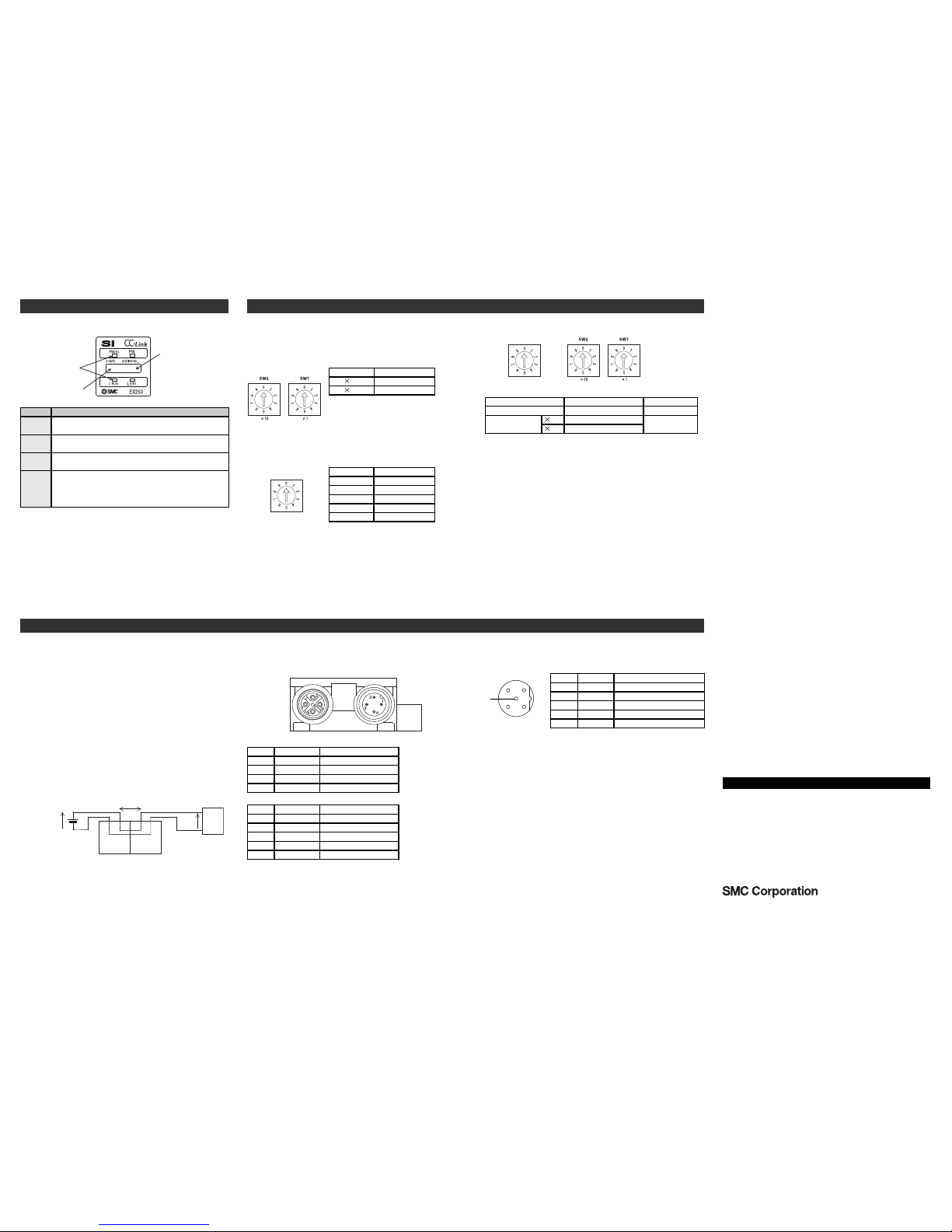
SW Setting
Wiring
N
ames and Functions of Individual Parts.
(continue)
x10 x1
Indication Contents
PW
Light ON : Input and control power is ON.
Light OFF: Input and control power is OFF.
PW (V)
Light ON : When power supply for solenoidvalves is turned on.
Light OFF: When supply voltage decreases below 19V.
IN : M12 4pins(male)
OUT : M12 5pins (female)
Example of connected cable : CORRENS VA-4DSB∗CCG etc.
Pin No. Description Function
1 SLD Shield
2 DB Communication wire DB
3 DG Communication wire DG
4 DA Communication wire DA
SW Setting
The Station No. and Baud rate are set by the rotary switch inside of the
SI unit cover.
Set parameters while the power of SI unit is off.
LED indication
L RUN
Light ON : Communication is normal.
Light OFF: Communication terminated. (Time over error)
L ERR
Light ON : Communication error.
Flashing : Assignment of station no. and baud rate are made
during communication .(Flashing every 0.4 s)
Light OFF: Communication is normal.
Communication connector (Bus adapter)Wiring power supply
The Power supply connection inside the unit has individual supplies
for solenoid valve actuation (SV power supply) and for Control parts
and Sensor (SI • SW power supply). Supply 24V DC for each of
them.
23V DC
+
-
Power for a sensor is supplied to the sensor connected to an input
Block.
There will be a voltage drop of up to approx. 1V inside the SI unit,
therefore select a sensor which will operate with the resultant
voltage.
If sensor requires 24V, it is necessary to lower power supply voltage
for sensor slightly or secure a power supply for sensor separately
without going through the SI unit so that sensor input voltage can
be 24V with actual loading (allowable voltage of power supply :
19.2V to 28.8 V).
IN side
Pin No. Description Function
1 SLD Shield
Communication wire DB
Communication wire DG
2 DB
3 DG
4 DA Communication wire DA
OUT side
5 - Unused
M12 5pins reverse (male)
Example of connected cable : P5032-66-∗ etc.
Power supply connector
32
1
4
5
Pin No. Description
Function
1 SV24V
+24V for solenoid valve
0V for solenoid valve
+24V for SI unit and Input Block
2 SV0V
3 SW24V
4 SW0V
0V for SI unit and Input Block
5 E
Earth
Station No. Setting
Setting Setting range
10 0 to 6
0 to 91
∗: Set stations within 01 to 63.
"L ERR" display lights if 00 and station 64
or larger is selected.
Turn off the power and select correct
station.
∗
: "L ERR" display blinks if the switch is
operated when the power is on.
Setting Baud rate
0 156 kpbs
625 kpbs1
∗: Set baud rate within 0 to 4.
"L ERR" display lights if the setting is out
of 0 to 4.
Set correct value after cutting the power
supply.
∗: "L ERR" display blinks if the switch is
operated when the power is on.
∗: Select baud rate the same as master
station.
2.5 Mbps2
10 Mbps4
5 Mbps3
Adjustment when shipped
Setting of rotary switch contents
0 156kbps
-
0
Please refer the table below for setting at the time of shipment from the factory.
B
aud rate Setting
Set parameters
B RATE(baud rate)
10
1
STATION NO.
0
"PW", "PW(V)", "L RUN" light while data link is normal.
EX250-TFI74GB-A
Rotary switch for
baud rate setting
Rotary switch for
Station no. setting
LED
Voltage reduction of max. 1V
SI unit
Input Block
Sensor
Si-SW power
24V DC
S
TATION NO.
B RATE
STATION NO.
B RATE
OUT
I
N
AUSTRIA (43) 2262 62280 NETHERLANDS (31) 20 531 8888
BELGIUM (32) 3 355 1464 NORWAY (47) 67 12 90 20
CZECH REP.
(420) 541 424 611
POLAND (48) 22 211 9600
DENMARK (45) 7025 2900 PORTUGAL (351) 21 471 1880
FINLAND (358) 207 513513 SLOVAKIA (421) 2 444 56725
FRANCE (33) 1 6476 1000 SLOVENIA (386) 73 885 412
GERMANY (49) 6103 4020 SPAIN (34) 945 184 100
GREECE (30) 210 271 7265 SWEDEN (46) 8 603 1200
HUNGARY (36) 23 511 390 SWITZERLAND (41) 52 396 3131
IRELAND (353) 1 403 9000 UNITED KINGDOM (44) 1908 563888
ITALY (39) 02 92711
URL http://www.smcworld.com (Global) http://www.smceu.com (Europe)
Specifications are subject to change without prior notice from the manufacturer.
© SMC Corporation All Rights Reserved.
Contact
 Loading...