

SMC Networks EX250-SDN1-X102, EX250-SDN1 Installation & Maintenance Manual
Installation & Maintenance Manual
SI unit - DeviceNet compatible
Type EX2 50-SDN1/ EX250-SDN1-X102
The unit and this manual contain essential information
to protect users and others from possible injury and property
damage and to ensure correct handling.
Please confirm that you fully understand the meaning of the
following messages (signs) before reading the text, and always
f
ollow the instructions.
Please read the Installation & Maintenance Manual for related
apparatus and understand it before operating the actuator.
Read this manual and follow the instructions.
Signal words such as WARNING, CAUTION and NOTE,
will be followed by important safety information that must
be reviewed carefully.
IMPORTANT MESSAGES
Indicates a potentially hazardous situation
which could result in death or serious injury
if you do not follow instructions.
Provides you helpful information.
Do not disassemble, modify (including change of printed
circuit board) or repair.
An injury or failure can result.
Do not operate outside of the specification range.
Fire, malfunction or damage can result.
Please use it after confirming the specification.
Do not use the product in environments with possible
presence of flammable, explosive or corrosion gas.
Otherwise fire, explosion or corrosion can result.
The product is not designed to be explosion proof.
.
Connect wires and cables correctly.
.
Do not connect wires while the power is on.
.
Do not lay wires or cables with the same wiring route as a power line or
high-voltage line.
.
Verify the insulation of the wiring.
.
Take prop er measur es agains t noise such as a n oise filt er when the
product is incorporated in equipment or devices.
.
Select an operation environment according to enclosure(IP67).
.
Take sufficient shielding measures when installing the product at the
following place.
(1)A place where a noise due to static electricity etc. is generated
(2)A place of high electric field strength
(3)A place possibly exposed to radioactivity
(4)A place near power cable
.
Do not use the product nearby a place where an electric surge is
generated.
.
Use the product equipped with a surge absorber when a surgegenerating load such as a solenoid valve is driven directly.
.
Prevent foreign matter such as remnant of wires from entering the
product.
.
Do not expose the product to vibration and impact.
.
Keep the specified ambient temperature range (+5 to +45 ).
.
Do not expose the product to heat radiation from a heat source
located nearby.
.
Use a precision screw driver with small flat blade when setting
rotary switch and DIP switch.
.
Perform maintenance and check at regular intervals.
.
Perform a proper functional check.
.
Do not clean the product with chemicals such as benzine and
thinner.
Specification
Safety Instructions
Indicates a potentially hazardous situation
which if not avoided, may result in minor
injury or moderate injury.
Do not apply voltages exceeding 250V between a lead
wire and a metal fitting.
Pay attention to perform an insulation test because it could
damage the insulation of the lead wire and cause failure.
These instructions must be followed when using the
product in an interlocking circuit:
.Provide double interlocking through another system
such as mechanical protection.
.Check the product regularly to ensure proper operation.
Otherwise malfunction can cause an accident.
These instructions must be followed when performing
maintenance work:
.Turn off the power supply
.Stopthe air supply, exhaustthe residual pressure and verify
that the air is releasedbefore performing maintenance work.
Otherwise it can cause injury.
Perform a proper functional check after completing
m
aintenance work.
S
top operation when an abnormality is observed or the product is
not working properly.
Safety cannot be assured due to unexpected malfunctions.
NOTE
The direct-current power supply should be a UL authorized power
s
upply.
1.Limited voltage current circuit in accordance with UL508
A circuit to which power is supplied by the secondary coil of
a transformer that meets the following conditions.
.
Max. voltage(with no load): less than 30Vrms(42.4V peak)
.
Max. current:(1)less than 8A(including when short circuited)
(2)limited by circuit protector (such as fuse) with
the following ratings
2.UL1310 compatible class 2 power supply unit or circuit of
max. 30Vrms (42.4V peak) or less using a UL1585 compatible
class 2 transformer as power supply. (Class 2 circuit)
Follow the instructions given below when handling the product.
Failure to follow instructions may damage the unit.
.
Operate the product within the specified voltage range.
.
Reserve a space around the unit for maintenance.
.
Do not remove labels.
.
Do not drop, hit or apply excessive shock to the product.
.
Do not bend or apply tensile force to cables, or apply a force by placing
a heavy load on them.
Noloadvoltage (Vpeak)
0 to 20 [V]
20 to 30 [V]
Max.current rating (A)
5.0
100 / peak voltage
Item Specification
Operating ambient temp. +5 to +45
Operatingambient humidity 35 to 85% RH (No dew condensation)
Storage ambient temp. -20 to +60
Vibration proof
10 to 57Hz 0.35mm(Constant amplitude)
57 to 150Hz 50m/s
2
(Constant acceleration)
Impact proof
150m/s2(peak), 11ms three times in each
direction±X, Y and Z.
Noise immunity
Normal mode :±1500V Pulse duration 1us
Common mode :
±
1500V Pulse duration 1us
Radiation :
±
1000V Pulse duration 1us
Withstand voltage 500V AC for 1min.
Insulation resistance 500V DC min10M ohm
Operating environment No corrosive gas and no dust
General specification
Item Specification
Applicable system DeviceNet Release 2.0
Power voltage
range
Current
consumption
Powerfor SI unit
Current consumption
11 to 25V DC
100mA or less
Power for Input
BlockCurrent
consumption
19.2 to 28.8V DC
Depending on the number of Input
Block stations and sensor
specifications. Max 1A or less
Powerfor solenoid
valve
Current consumption
21.6 to 26.4V DC (Power reduction
alarm occurs at approx. 19V DC.)
Depending on number of Solenoid
valve station and specifications Max
2.5A or less
Solenoid valve
connectionspec.
Output type
P-ch MOS-FET Open drain type
Connection load
Solenoid valve with protection circuit for
24V DC and 1.5W or less surge
voltage. (made by SMC)
Insulation type Optocoupler type
Residual voltage 0.3V DC or less
Network connection spec.
MAC ID setting range
0 to 63
(Set by DIP/ retain addressinformation
when setting power is shut off via
network.)
Baud Rate
(Transmission speed)
500kbps, 250kbps, 125kbps
(Setby DIP / hold address information
when setting power is shut off via
network.)
Slave (branch station) type Group 2 only server
Connection type T branch type, Multi drop type
Device type 27
Product code 2401
Revision Refer to EDS file
Vendor ID 7
Consumed connection size
(Receiving byte)
4(PolledI/Oconnection: Occupy4 byte)
Produced connection size
(Sending byte)
4
(PolledI/Oconnection
:Occupy4byte)
Correspond message
Polled command (I/O message),
Explicit message.
Electrical and network
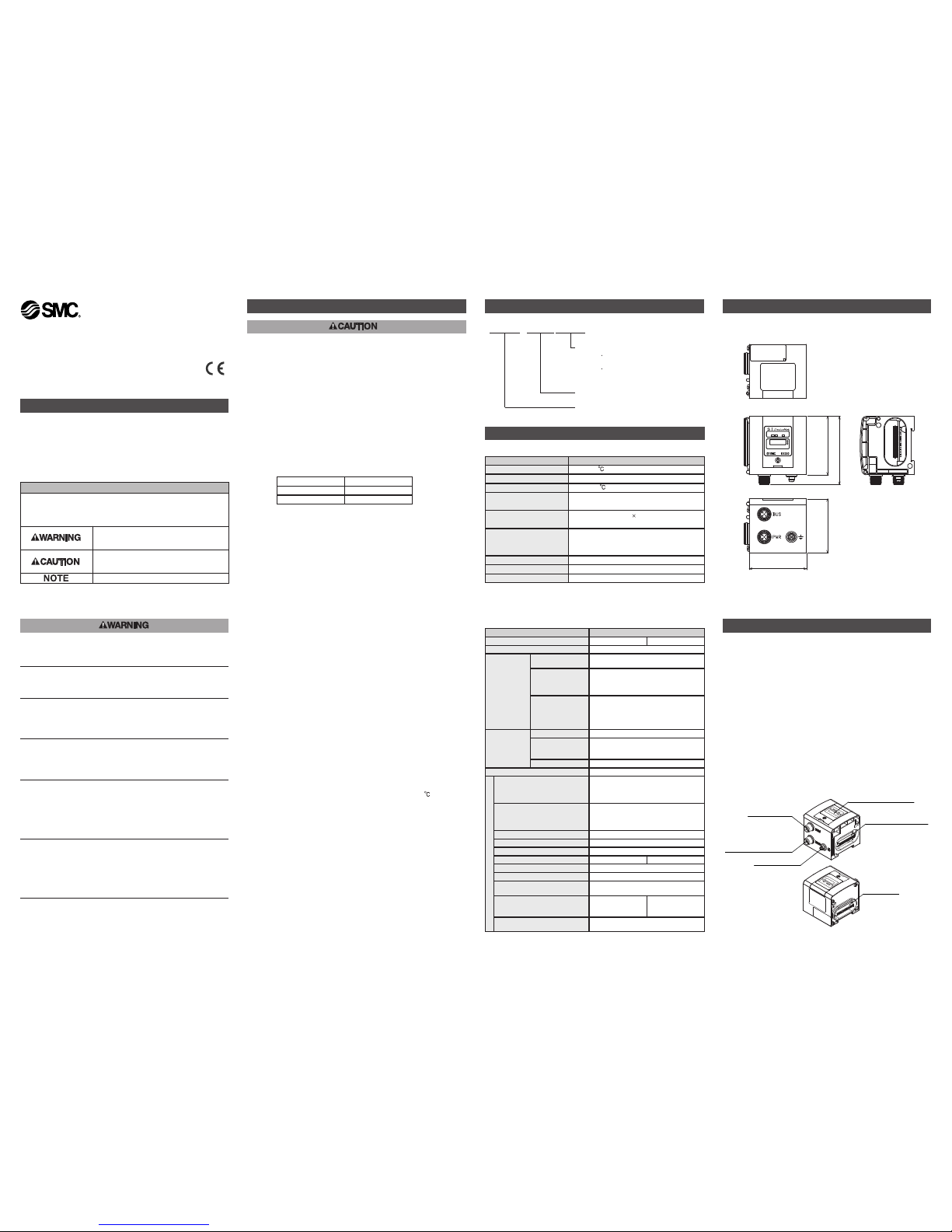
Names and Functions of Individual Parts
Output equipment
connector
Indication and address
setting panel
Communication
connector
Ground terminal
Power supply connector
for output equipment,
SI unit and Input block
Input block
connector
Body
.
Communication connector
To send and receive communication signals through DeviceNet line.
.
Power supply connector for output equipment, SI unit and Input block
To supply power to the output equipment such as a solenoid
valve, and output block, SI unit and Input block.
.
Output equipment connector
To connect the output equipment such as a solenoid valve
and output block.
.
Input block connector
To connect the Input block.
.
Indication and address setting panel
To provide LED's to indicate the condition of the unit,
and the setting of address and HOLD/CLEAR functions.
.
Ground terminal
To be connected to the ground.
Outline with Dimensions (in mm)
64.4
74.9
59.8
63
Safety Instructions
(continue)
Model Indication Method
EX250 - SDN1 (X102)
SI Unit for DeviceNet
SI Unit Series
Special specification
X102 :
Without function to monitor supply
voltage for solenoid valve.
Number of occupied bytes is 6 for
input and 4 for output.
2404
Part No. EX250-SDN1
EX250-SDN1-X102
6
(PolledI/Oconnection
:Occupy6byte)
EX250-TFI73GB-A

Wiring
W
iring of power supply
T
he Power supply connection inside the unit has individual power
supplies for solenoid valve actuation (SV power supply) and for Sensor
(SW power supply). Supply 24V DC for each of them.
Either single or dual power supply is available. Wiring is not necessary
for SW power supply when no Input Blocks are used.
*
In case of single power supply, pay attention to the range of each
supply voltage.
Names and Functions of Individual Parts
(continue)
P
WR
(V)
PWR
MOD/NET
SETTINGS
1
0
PWR(V):
Power LED for
output equipment
PWR:
Power LED for SI unit
and Input block
MOD/NET
Indication Contents
PWR (V) Light ON when power for solenoid valve is supplied.
PWR Light ON when power for DeviceNet line is supplied.
MOD /
NET
Light OFF Power off,off line or Duplicate MAC ID.
Green
flashing
Waiting for connection (ON line)
Green
Light ON
Connection completed (ON line)
Red
flashing
Connection timed out (Minor communication
error)
Red
Light ON
MAC ID duplication error or BUS OFF error
(Major communication error)
Voltage reduction of approx.1V
2
4V DC
SI unit Input Block
2
3V DC Sensor
P
ower for a sensor is supplied to the sensor connected to an Input Block.
T
here will be a voltage drop of up to approx. 1V inside the SI unit,
therefore select a sensor which will operate with the resultant voltage.
I
f a sensor requires 24V, it is necessary to lower power supply voltage
f
or sensor slightly or secure a power supply for sensor separately without
going through the SI unit so that sensor input voltage can be 24V with
actual loading (allowable voltage of sensor power supply : 19.2V to
28.8V).
P
ower supply connector
M
12 5pin (Plug)
Communication connector
M12 5pin (Plug) [Special for DeviceNet]
32
14
5
32
1
4
5
No. Description Function
1 SV 24V For solenoid valve +24V
2 SV 0V For solenoid valve 0V
3 SW24V Forsensor unit +24V
4 SW 0V For sensor unit 0V
5 E Earth
No. Description Function
1 Drain Drain / Shield
2 V + Power supply + for circuit
3 V - Power supply - for circuit
4 CAN_H Signalwire H
5 CAN_L Signal wire L
SW Setting
Address setting
When DIP switch is to be set, turn OFF power supply to SI unit.
Position of DIP switch
DIP switch
M3 pan head screw
Tightening torque : 0.6N .m
SW1
1.Default value of address and baud rate.
Node address and baud rate are preset to 63, 125kbps respectively at
the shipment in either HWmode or SW mode.
2.In SW mode, setting value of address and baud rate are retained even
after power supply is off.
3.In HW mode, once power supply is turned off and turned on again,
then setting value of address and baud rate in S/W mode are erased.
Address and baud rate can be set again by setting switch SW1.
Example
4.Output with communication stopped is set to 0 (full output clear mode)
at shipment from factory. It is possible to change setting of single
output when communication stopped. In this case,setting of SW1-9
becomes invalid.
SW mode
Address : 63
Baud rate : 125kbps
HW mode
Address : 0
Baud rate : 500kbps
SW mode
Address : 0
Baud rate : 500kbps
L
ED indication
0
Set address and Baud rate
by SW1 to 8
Set address and Baud rate
by network.
SW1 to 8 are invalid.
HW mode
1
SW mode
Mode setting
Setting of solenoid output state in communication fault
Solenoid output state:Communication stops (I/O connection time out)
or fault message is received.
Solenoid output state
All solenoid valve outputs are held before communication fault.
(Fault state=1 , Fault value=0)
All solenoid outputs are reset to zero.
(Fault state=0 ,Fault value=0)
HOLD
CLEAR
SW9
1
0
Setting of address
Address
#0
#1
#2
#62
#63
SW1
1
0
1
0
0
1
SW2
2
0
0
1
1
1
SW3
4
0
0
0
1
1
SW4
8
0
0
0
1
1
SW5
16
0
0
0
1
1
SW6
32
0
0
0
1
1
Setting of Baud rate
SW7 SW8
Baud rate
(kbps)
0
1
0
1
0
0
1
1
Setting
125
250
500
Not used
...
1 2 3 4 5 6 7 8 9 10
ON
1
0
Error Display Function
MOD/NET LED Cause & Countermeasure
Light OFF
PWR LED Light OFF
<Countermeasure>
Confirm that power for SI unit circuit is supplied.
Confirm correct wiring for circuit.
If above countermeasures do not improve status, please
exchange SI unit.
PWR LED Light ON
<Countermeasure>
Confirm that baud rate is set correctly.
If MOD/NET LED light is OFF in spite of baud rate is set
correctly, exchange SI unit.
Green flashing
Connection waiting
Shows communication waiting status between SI unit and
master.
<Countermeasure>
Confirm master is operating correctly.
If using scan list, ensure slave is recorded to scan list
correctly.
Red flashing
Communication wire disconnected error
Warning for SV supply voltage drop
(Except for EX250-SDN1-X102)
<Countermeasure>
Confirm communication wire is connected.
Confirm SV power supply voltage is according to
specification. (21.6 to 26.4V)
(Except for EX250-SDN1-X102)
<Remark>
Red flashing if master power source is turned off during
communication.
Red Light ON
Node address overlapping error
<Countermeasure>
Confirm there is no overlapping on the node address.
BUS OFF error
Detects communication error.
<Countermeasure>
Case 1
Communication error due to noise.
Confirm there is no component or high voltage cable that
generates noise around communication wire.
Make some distances between communication wire and
noise source.
Case2
Communication cable problem
Confirm terminal resistance (121ohm) is connected to
both ends of DeviceNet communication wire.
If red MOD/NET LED is still ON despite above
countermeasures, exchange SI unit.
When red MOD/NET LED is ON, even if cause is solved, the SI unit
does not perform auto-recovery. In this case, please reset the power
to SI unit circuit (Communication/Internal power supply).
E
rror Display Function
(continue)
EX250-TFI73GB-A
AUSTRIA (43) 2262 62280 NETHERLANDS (31) 20 531 8888
BELGIUM (32) 3 355 1464 NORWAY (47) 67 12 90 20
CZECH REP.
(420)541 424 611
POLAND (48) 22 211 9600
DENMARK (45) 7025 2900 PORTUGAL (351) 21 471 1880
FINLAND (358) 207 513513 SLOVAKIA (421)2 444 56725
FRANCE (33) 1 6476 1000 SLOVENIA (386) 73 885 412
GERMANY (49) 6103 4020 SPAIN (34) 945 184 100
GREECE (30) 210 271 7265 SWEDEN (46) 8 603 1200
HUNGARY (36) 23 511 390 SWITZERLAND (41) 52 396 3131
IRELAND (353) 1 403 9000 UNITED KINGDOM (44) 1908 563888
ITALY (39) 02 92711
URL http://www.smcworld.com (Global) http://www.smceu.com (Europe)
Specifications are subject to change without prior notice from the manufacturer.
© SMC Corporation All Rights Reserved.
Contact
 Loading...