

SMC Networks EX250-SCA1A Installation & Maintenance Manual
Installation & Maintenance Manual
SI unit-CANopen compatible
Type EX250-SCA1A
The unit and this manual contain essential information
to protect users and others from possible injury and property
damage and to ensure correct handling.
Please confirm that you fully understand the meaning of the
following messages (signs) before reading the text, and always
follow the instructions.
Please read the Installation & Maintenance Manual for related
apparatus and understand it before operating the actuator.
Do not disassemble, modify (including change of printed
circuit board) or repair.
An injury or failure can result.
Do not operate outside of the specification range.
Fire, malfunction or damage can result.
Please use it after confirming the specification.
Do not use the product in environments with possiblepresence of flammable, explosive or corrosion gas.
Otherwise fire, explosion or corrosion can result.
The product is not designed to be explosion proof.
.
Connect wires and cables correctly.
.
Do not connect wires while the power is on.
.
Do not lay wires or cables with the same wiring route as a power line or
high-voltage line.
.
Verify the insulation of the wiring.
.
Take proper measures against noise such as a noise filter when the
product is incorporated in equipment or devices.
.
Select an operation environment according to enclosure(IP67).
.
Take sufficient shielding measures when installing the product at the
following place.
(1)A place where a noise due to static electricity etc. is generated
(2)A place of high electric field strength
(3)A place possibly exposed to radioactivity
(4)A place near power cable
.
Do not use the product nearby a place where an electric surge is
generated.
.
Use the product equipped with a surge absorber when a surgegenerating load such as a solenoid valve is driven directly.
.
Prevent foreign matter such as remnant of wires from entering the
product.
.
Do not expose the product to vibration and impact.
.
Keep the specified ambient temperature range (-10 to +50
ºC).
.
Do not expose the product to heat radiation from a heat source located
nearby.
.
Use a precision screw driver with small flat blade when setting rotary
switch and DIP switch.
.
Perform maintenance and check at regular intervals.
.
Perform a proper functional check.
.
Do not use the product with chemicals such as benzine and thinner.
Specification
Safety Instructions
Do not apply voltages exceeding 250V between a lead
wire and a metal fitting.
Pay attention to perform an insulation test because it could
damage the insulation of the lead wire and cause failure.
These instructions must be followed when using the
product in an interlocking circuit:
.Provide double interlocking through another system
such as mechanical protection.
.Check the product regularly to ensure proper operation.
Otherwise malfunction can cause an accident.
These instructions must be followed when performing
maintenance work:
.Turn off the power supply
.Stop the air supply, exhaust the residual pressure and
verify that the air is released before performing
maintenance work.
Otherwise it can cause injury.
Perform a proper functional check after completing
maintenance work.
Stop operation when an abnormality is observed or the product is
not working properly.
Safety cannot be assured due to unexpected malfunctions.
NOTE
The direct-current power supply should be a UL authorized power
supply.
1.Limited voltage current circuit in accordance with UL508
A circuit to which power is supplied by the secondary coil of a
transformer that meets the following conditions.
.
Max. voltage(with no load): less than 30Vrms(42.4V peak)
.
Max. current:(1)less than 8A(including when short circuited)
(2)limited by circuit protector (such as fuse) with the
following ratings
2.UL1310 compatible class 2 power supply unit or circuit of max.
30Vrms (42.4V peak) or less using a UL1585 compatible class 2
transformer as power supply. (Class 2 circuit)
Follow the instructions given below when handling the product.
Failure to follow instructions may damage the unit.
.
Operate the product within the specified voltage range.
.
Reserve a space around the unit for maintenance.
.
Do not remove labels.
.
Do not drop, hit or apply excessive shock to the product.
.
Do not bend or apply tensile force to cables, or apply a force by placing
a heavy load on them.
General specification
Electrical and network specifications
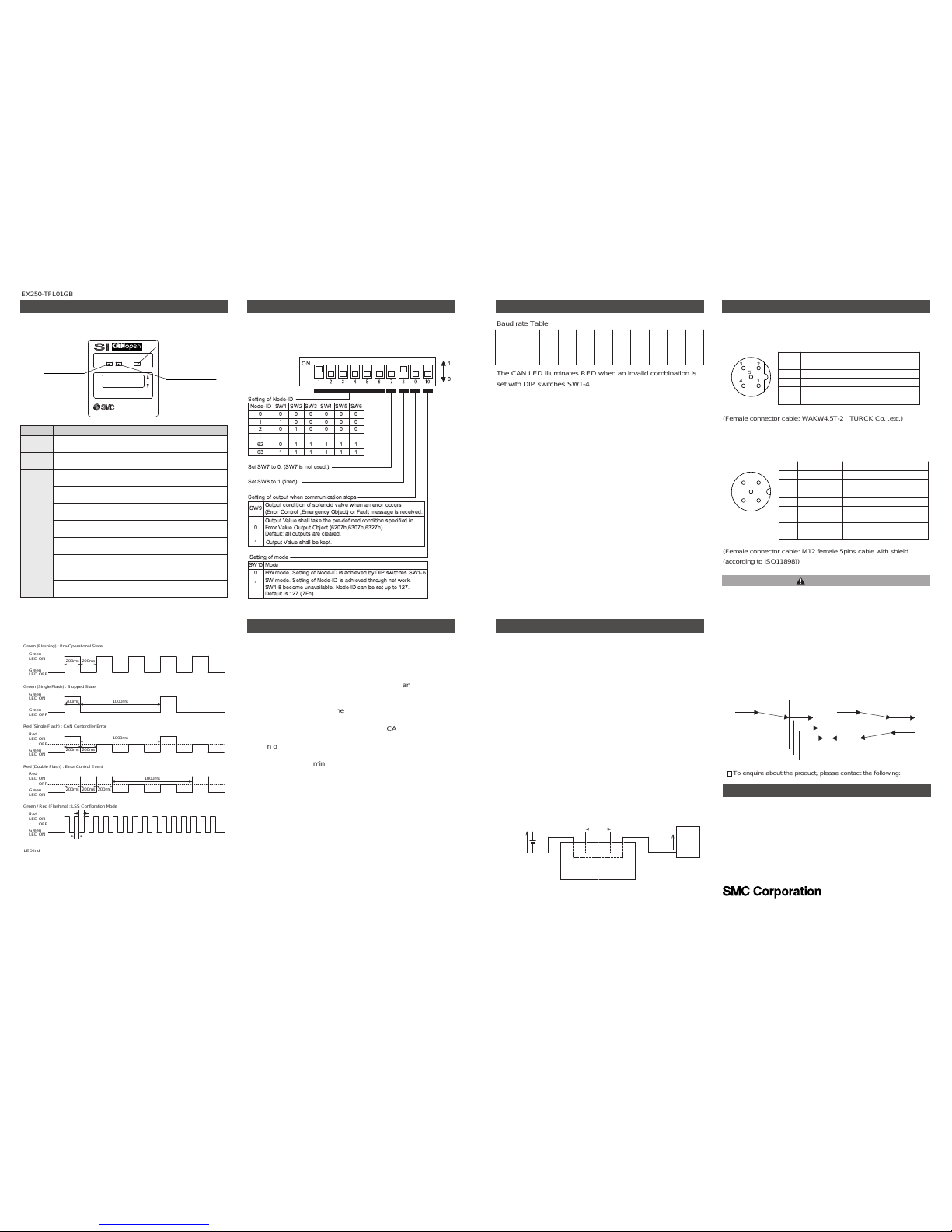
Names and Functions of Individual Parts
Output equipment
connector
Indication and address
setting panel
Communication
connector
Ground terminal
Power supply connector
for output equipment,
SI unit and Input block
Input block connector
Body
.
Communication connector
To send and receive communication signals through CANopen line.
To receive the power supply for SI unit.
.
Power supply connector for output equipment, Input block
To supply power to the output equipment such as a solenoid
valve, and output block, Input block.
.
Output equipment connector
To connect the output equipment such as a solenoid valve and
output block.
.
Input block connector
To connect the Input block.
.
Indication and address setting panel
To provide LED's to indicate the condition of the unit, and the
setting of address and HOLD/CLEAR functions.
.
Ground terminal
To be connected to the ground.
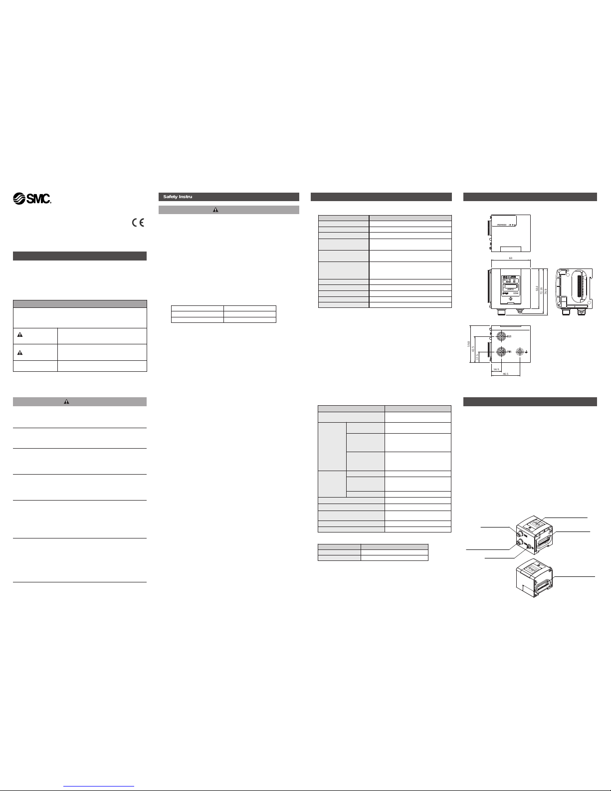
Outline with Dimensions (in mm)
EX250-SCA1
SI UNIT
PWR(V) CANPWR
ADDRESS
1
0
EX250
BUS
PWR
64.4
72.16
74.9
63
17.5
42.5
59.8
16.5
46.5
Safety Instructions
(continued)
Applicable solenoid valve series
EX250-TFL01GB
IMPORTANT MESSAGES
Read this manual and follow the instructions.
Signal words such as WARNING, CAUTION and NOTE, will be
followed by important safety information that must be reviewed
carefully.
Indicates a potentially hazardous situation
which could result in death or serious injury if
you do not follow instructions.
Indicates a potentially hazardous situation
which if not avoided, may result in minor injury
or moderate injury.
Provides you helpful information.
WARNING
CAUTION
NOTE
WARNING
CAUTION
No load voltage (V peak) Max.current rating (A)
0 to 20 [V] 5.0
Above 20 to 30 [V] 100 / peak voltage
Item Specification
Operating ambient temp.
-10 to +50ºC
Operating ambient humidity 35 to 85% RH (No dew condensation)
Storage ambient temp.
-20 to +60ºC
Vibration proof 10 to 57Hz 0.35mm (Constant amplitude)
57 to 150Hz 50m/s
2
(Constant acceleration)
Impact proof 100m/s2(peak), 11ms x three times in each
direction
±
X, Y and Z
Noise immunity Normal mode : ±1500V Pulse duration 1us
Common mode :
±
1500V Pulse duration 1us
Radiation :
±
1000V Pulse duration 1us
Withstand voltage 500V AC for 1min.
Insulation resistance 500V DC min 10M ohm
Operating environment No corrosive gas and no dust
Weight About 250g
IP protection IP67
Item Specification
Applicable system CANopen CiA DS-301 V4.02 and
CiA DS-401
Power voltage
range
Current
consumption
Power for SI unit
Current consumption
18 to 30V DC (24VDC typical.)
100mA or less
Power for Input
Block
Current
consumption
19.2 to 28.8V DC
Depending on the number of Input
Block stations and sensor
specifications. Max 1.0A or less
Power for solenoid
valve
Current consumption
22.8 to 26.4V DC
Depending on the number of
solenoid valve stations and
specifications. Max 2.0A or less
Solenoid valve
connection
spec.
Output type P-ch MOS-FET Open drain type
Connection load Solenoid valve with protection
circuit for 24V DC and 1.5W or less
surge voltage. (made by SMC)
Insulation type Opto coupler type
Residual voltage 0.3V DC or less
Node-ID setting range 1 to 63 (1 to 127 at the SW mode)
Baudrate setting range
(Transmission speed)
1000k,800k,500k,250k,125k,50k,
20k,10kbps
COB-Identifier 11bit ID(CAN2.0A)
Input /Output 32 points/32 points
Valve type Valve Series
VQC series VQC1000, VQC2000, VQC4000
SV series SV1000, SV2000, SV3000
Wiring
Wiring of power supply
The Power supply connection inside the unit has individual power
supplies for solenoid valve actuation (SV power supply) and for
Control parts and Sensor (SW power supply). Supply 24V DC for
each of them. Either single or dual power supply is available. Wiring
is not necessary for SW power supply when no Input Blocks are
used.
Names and Functions of Individual Parts
(continued)
PWR(V) CANPWR
ADDRESS
1
0
EX250
CAN
PWR:
Power LED for SI unit
and Input block
PWR(V):
Power LED for
output equipment
SI unit Input block
Sensor
23V DC
24V DC
Voltage reduction of approx.1V
Power for a sensor is supplied to the sensor connected to an Input
Block. There will be a voltage drop of up to approx. 1V inside the SI
unit, therefore select a sensor which will operate with the resultant
voltage.
If a sensor requires 24V, it is necessary to lower power supply
voltage for sensor slightly or secure a power supply for sensor
separately without going through the SI unit so that sensor input
voltage can be 24V with actual loading (allowable voltage of sensor
power supply: 19.2V to 28.8V).
Power supply connector
Power supply connector M12 male 5pins reverse key type
Communication connector
Communication connector M12 male 5pins
3 2
14
5
SW Setting
Address setting
When DIP switch is to be set, turn OFF power supply to SI unit.
LED indication
Node-ID
SW1
0 0
1 1
2 0
62 0
63 1
SW2
0
0
1
1
1
SW3
0
0
0
1
1
SW4
0
0
0
1
1
SW5
0
0
0
1
1
SW6
0
0
0
1
1
SW9
0
Output Value shall take the pre-defined condition specified in
Error Value Output Object (6207h,6307h,6327h)
Default: all outputs are cleared.
1 Output Value shall be kept.
Output condition of solenoid valve when an error occurs
(Error Control ,Emergency Object) or Fault message is received.
SW10
1
SW mode. Setting of Node-ID is achieved through net work.
SW1-8 become unavailable. Node-ID can be set up to 127.
Default is 127 (7Fh).
Mode
0 HW mode. Setting of Node-ID is achieved by DIP switches SW1-6.
....
1
0
ON
To enquire about the product, please contact the following:
3 2
14
5
Baud rate Table
The CAN LED illuminates RED when an invalid combination is
set with DIP switches SW1-4.
EX250-TFL01GB
(Female connector cable: WAKW4.5T-2 TURCK Co. ,etc.)
(Female connector cable: M12 female 5pins cable with shield
(according to ISO11898))
Green
LED ON
Green
LED OFF
Green
LED ON
Green
LED OFF
Red
LED ON
Green
LED ON
200ms
200ms
OFF
Red
LED ON
Green
LED ON
OFF
200ms
200ms
200ms
1000ms
1000ms
200ms
200ms 200ms
1000ms
Red
LED ON
Green
LED ON
OFF
LED Indication of SI unit is based on CANopen Specification (CANopen Spec.DR-303-3).
Refer to DR-303-3 Indicator Specification for details.
50ms
50ms
Baud Rate
The baud rate can be set in the HW mode using the following
methods: -
Method of re-setting to default baud rate (125kbps)
1) Turn off the power supply (for CANopen line) and set NodeID to 0 with DIP switches SW1-6.
2) The CAN LED will flash RED for five seconds at the
frequency of 2Hz when the power supply to the SI unit is
restored.
3) The baud rate is set to 125kbps and the CAN LED illuminates
green and red alternately (2Hz).
4) Turn off the power supply, set Node-ID, and turn on the
power supply again.
5) The CAN LED illuminates (GREEN). The SI units state of
communication is standby (When SI unit is stand by mode
Pre-operational).
Method of setting baud rate to value within CiA
specification
1) Turn OFF the power supply (for CANopen line) and set
Node-ID to 0 with DIP switches SW1-6.
2) The CAN LED will flash RED for five seconds at the
frequency of 2Hz when the power supply to the SI unit is
restored.
3) Set DIP switch SW6 to 1 while the CAN LED is flashing
(within five seconds).
4) The Flashing CAN LED stops (CAN LED is off). Set the baud
rate with DIP switches SW1-4 within ten seconds according
to the following table.
Wiring
(continued)
Baud Rate
(continued)
<Example: If the baud rate of the SI unit is set to 500kbps.>
Because the baud rate is 500kbps, DIP switches SW1-4 setting is 2.
i.e. SW1 = 0 , SW2 = 1 , SW3 = 0 and SW4 = 0
5) The CAN LED flashes RED for two seconds at the frequency
of 1Hz when the setting is successful.
6) After that, the CAN LED flashes RED for five seconds at a
frequency of 5Hz to acknowledge the end of the setting
procedure.
7) The CAN LED illuminates GREEN and RED alternately (at
the frequency of 2Hz).
8) Turn OFF the power supply, set the Node-ID, then turn ON
the power supply again.
9) The CAN LED will illuminate GREEN. The SI units state
ofcommunication is standby (Pre-operational mode).
It is the responsibility of the machine builder to make sure that the
machine operates correctly.
CANopen units from different manufacturers have different ability
(minimum message interval) respectively.
The machine builder should consider the differences in the ability.
The method (confirmed service) of sending the following request after
receiving the response to the request is recommended to ensure correct
communication.
When using the method (unconfirmed service) of sending the following
request without receiving a response to the request, if the request
exceeding the processing performance of the unit is sent, it cannot be
received.
Please confirm the normal operation beforehand when an SMC CANopen
unit is used in your machine.
Please consult with SMC when there is a problem.
Application X
Unconfirmed
service
Application Y, Z, ...
request
indication
indication
indication
Application X
Confirmed
service
Application Y
request
indication
confirmation
response
Indication Contents
PWR (V) Green Light ON
When power for solenoid valves and
output equipment is supplied
PWR Green Light ON
When power for CANopen line, SI unit
and input blocks is supplied
CAN
Green Light ON When SI unit is in the Operational state
Green Light
(flashing)
SI unit is in the Pre-Operational state
Green Light
(single flash)
Single flash when SI unit is in Stopped
state
Red Light
(single flash)
Single flash when CAN controller error
occurs
Red Light
(double flash)
Double flash when Error Control Event
occurs
Green / Red Light
(flashing)
Flashing when SI unit is in
Configuration mode
(LSS services)
Red Light ON SI unit is in “Bus OFF” state
DIP switches
SW1-4 setting
0 1 2 3 4 5 6 7 8
Baud rate
(kbps)
1000 800 500 250 125 - 50 20 10
CAUTION
No. Description Function
1 SV 24V +24V for solenoid valve.
2 SV 0V 0V for solenoid valve
3 SW 24V +24V for sensor input
4 SW 0V 0V for sensor input
5 E Earth
No. Description Function
1 CAN_SHLD Shield
2 CAN_V+
Power supply + for
CANopen
3 CAN_GND Power supply - for CANopen
4 CAN_H
CAN_H bus line
(dominant high)
5 CAN_L
CAN_L bus line
(dominant low)
URLhttp:/ /www.smcworld.com (Global) http://www.smceu.com (Europe)
AUSTRIA (43) 2262 62280 NETHERLANDS (31) 20 531 8888
BELGIUM (32) 3 355 1464 NORWAY (47) 67 12 90 20
CZECH REP. (420) 541 424 611 POLAND (48) 22 211 9600
DENMARK (45) 7025 2900 PORTUGAL (351) 21 471 1880
FINLAND (358) 207 513513 SLOVAKIA (421) 2 444 56725
FRANCE (33) 1 6476 1000 SLOVENIA (386) 73 885 412
GERMANY (49) 6103 4020 SPAIN (34) 945 184 100
GREECE (30) 210 271 7265 SWEDEN (46) 8 603 1200
HUNGARY (36) 23 511 390 SWITZERLAND (41) 52 396 3131
IRELAND (353) 1 403 9000 UNITED KINGDOM (44) 1908 563888
ITALY (39) 02 92711
Contact
Specifications are subject to change without prior notice from the manufacturer.
The descriptions of products in this document may be used by other companies.
© SMC Corporation All Rights Reserved.
 Loading...