

SMC Networks EX245-SPN1A, EX245-SPN2A, EX245-EA2-1, EX245-EA2-2, EX245-SPN3A Operation Manual
...Page 1
No.EX※※-OMW0011-A
PRODUCT NAME
SI Unit
MODEL / Series / Product Number
EX245-SPN1A
EX245-SPN2A
EX245-SPN3A
PRODUCT NAME
Digital Input Module
MODEL / Series / Product Number
EX245-DX1
PRODUCT NAME
Digital Output Module
MODEL / Series / Product Number
EX245-DY1
PRODUCT NAME
End Plate
MODEL / Series / Product Number
EX245-EA2-1
EX245-EA2-2
EX245-EA2-3
EX245-EA2-4
EX245-EA2-5
Page 2

- 2 -
No.EX※※-OMW0011-A
Contents
1. Product Summary 10
1.1. Features 10
1.2. Structure 11
2. General Specifications 12
3. Installation 13
3.1. Mounting 13
3.2. Wiring 15
4. Commissioning 21
4.1. Configuration 21
4.2. Parameterisation 24
5. Diagnosis 27
5.1. Diagnostics data on I/O mapping 27
5.2. Maintenance alarm for the Fibre-optic cables 31
6. SI Unit 32
6.1. Parts and description 32
6.2. Specifications 34
6.3. Process data for valves 36
6.4. LED indicators 37
6.5. Block diagram 40
7. Digital Input Module - EX245-DX1 43
7.1. Parts and description 43
7.2. Specifications 44
7.3. Wiring 45
7.4. Process data 45
7.5. LED indicators 46
7.6. Block diagram 47
8. Digital Output Module - EX245-DY1 48
8.1. Parts and description 48
8.2. Specifications 49
8.3. Wiring 50
8.4. Process data 50
8.5. LED indicators 51
8.6. Block diagram 52
9. End Plate - EX245-EA2-1/2/3/4/5 53
9.1. Parts and description 53
9.2. Specifications 56
Page 3

- 3 -
No.EX※※-OMW0011-A
10. Accessories 57
10.1. Markers 57
10.2. Y Connector 58
10.3. Seal cap 60
10.4. Joint pack 62
11. Dimensions 63
11.1. The Input/Output Modules Manifold 63
12. Troubleshooting 64
12.1. EX245-SPN1A/SPN2A/SPN3A 64
12.2. EX245-DX1 66
12.3. EX245-DY1 66
Page 4
- 4 -
No.EX※※-OMW0011-A
Safety Instructions
These safety instructions are intended to prevent hazardous situations and/or equipment damage.
These instructions indicate the level of potential hazard with the labels of "Caution", "Warning" or "Danger".
They are all important notes for safety and must be followed in addition to International Standards
(ISO/IEC)*1), and other safety regulations.
*1) ISO 4414: Pneumatic fluid power -- General rules relating to systems.
ISO 4413: Hydraulic fluid power -- General rules relating to systems.
IEC 60204-1: Safety of machinery -- Electrical equipment of machines. (Part 1: General requirements)
ISO 10218: Manipulating industrial robots -Safety.
etc.
Caution
Caution indicates a hazard with a low level of risk which, if not avoided, could
result in minor or moderate injury.
Warning
Warning indicates a hazard with a medium level of risk which, if not avoided,
could result in death or serious injury.
Danger
Danger indicates a hazard with a high level of risk which, if not avoided, will
result in death or serious injury.
Warning
1. The compatibility of the product is the responsibility of the person who designs the
equipment or decides its specifications.
Since the product specified here is used under various operating conditions, its compatibility with specific
equipment must be decided by the person who designs the equipment or decides its specifications
based on necessary analysis and test results.
The expected performance and safety assurance of the equipment will be the responsibility of the person
who has determined its compatibility with the product.
This person should also continuously review all specifications of the product referring to its latest catalog
information, with a view to giving due consideration to any possibility of equipment failure when
configuring the equipment.
2. Only personnel with appropriate training should operate machinery and equipment.
The product specified here may become unsafe if handled incorrectly.
The assembly, operation and maintenance of machines or equipment including our products must be
performed by an operator who is appropriately trained and experienced.
3. Do not service or attempt to remove product and machinery/equipment until safety is
confirmed.
1. The inspection and maintenance of machinery/equipment should only be performed after measures to
prevent falling or runaway of the driven objects have been confirmed.
2. When the product is to be removed, confirm that the safety measures as mentioned above are
implemented and the power from any appropriate source is cut, and read and understand the specific
product precautions of all relevant products carefully.
3. Before machinery/equipment is restarted, take measures to prevent unexpected operation and malfunction.
4. Contact SMC beforehand and take special consideration of safety measures if the
product is to be used in any of the following conditions.
1. Conditions and environments outside of the given specifications, or use outdoors or in a place
exposed to direct sunlight.
2. Installation on equipment in conjunction with atomic energy, railways, air navigation, space, shipping,
vehicles, military, medical treatment, combustion and recreation, or equipment in contact with food and
beverages, emergency stop circuits, clutch and brake circuits in press applications, safety equipment or
other applications unsuitable for the standard specifications described in the product catalog.
3. An application which could have negative effects on people, property, or animals requiring special
safety analysis.
4. Use in an interlock circuit, which requires the provision of double interlock for possible failure by using
a mechanical protective function, and periodical checks to confirm proper operation.
Page 5
- 5 -
No.EX※※-OMW0011-A
Safety Instructions
Caution
1.The product is provided for use in manufacturing industries.
The product herein described is basically provided for peaceful use in manufacturing industries.
If considering using the product in other industries, consult SMC beforehand and exchange
specifications or a contract if necessary.
If anything is unclear, contact your nearest sales branch.
Limited warranty and Disclaimer/Compliance Requirements
The product used is subject to the following "Limited warranty and Disclaimer" and "Compliance
Requirements".
Read and accept them before using the product.
Limited warranty and Disclaimer
1. The warranty period of the product is 1 year in service or 1.5 years after the product is
delivered, whichever is first.2)
Also, the product may have specified durability, running distance or replacement parts.
Please consult your nearest sales branch.
2. For any failure or damage reported within the warranty period which is clearly our
responsibility, a replacement product or necessary parts will be provided.
This limited warranty applies only to our product independently, and not to any other
damage incurred due to the failure of the product.
3. Prior to using SMC products, please read and understand the warranty terms and
disclaimers noted in the specified catalog for the particular products.
2) Vacuum pads are excluded from this 1 year warranty.
A vacuum pad is a consumable part, so it is warranted for a year after it is delivered.
Also, even within the warranty period, the wear of a product due to the use of the
vacuum pad or failure due to the deterioration of rubber material are not covered by the
limited warranty.
Compliance Requirements
1. The use of SMC products with production equipment for the manufacture of weapons of mass
destruction (WMD) or any other weapon is strictly prohibited.
2. The exports of SMC products or technology from one country to another are governed by the
relevant security laws and regulation of the countries involved in the transaction. Prior to the
shipment of a SMC product to another country, assure that all local rules governing that export are
known and followed.
Page 6
- 6 -
No.EX※※-OMW0011-A
Operator
This operation manual is intended for those who have knowledge of machinery using pneumatic
equipment, and have sufficient knowledge of assembly, operation and maintenance of such
equipment. Only those persons are allowed to perform assembly, operation and maintenance.
Read and understand this operation manual carefully before assembling, operating or providing
maintenance to the product.
■Safety Instructions
Warning
■Do not disassemble, modify (including changing the printed circuit board) or repair.
An injury or failure can result.
■Do not operate or set with wet hands.
This may lead to an electric shock.
■Do not operate the product outside of the specifications.
Do not use for flammable or harmful fluids.
Fire, malfunction, or damage to the product can result.
Verify the specifications before use.
■Do not operate in an atmosphere containing flammable or explosive gases.
Fire or an explosion can result.
This product is not designed to be explosion proof.
■If using the product in an interlocking circuit:
•Provide a double interlocking system, for example a mechanical system.
•Check the product regularly for proper operation.
Otherwise malfunction can result, causing an accident.
■The following instructions must be followed during maintenance:
•Turn off the power supply.
•Stop the air supply, exhaust the residual pressure and verify that the air is released before performing
maintenance.
Otherwise an injury can result.
Page 7
- 7 -
No.EX※※-OMW0011-A
Caution
■When handling the unit or assembling/replacing units:
•Do not touch the sharp metal parts of the connector or plug for connecting units.
•Take care not to hit your hand when disassembling the unit.
The connecting portions of the unit are firmly joined with seals.
•When joining units, take care not to get fingers caught between units.
An injury can result.
■After maintenance is complete, perform appropriate functional inspections.
Stop operation if the equipment does not function properly.
Safety cannot be assured in the case of unexpected malfunction.
■Provide grounding to assure the noise resistance of the Fieldbus system.
Individual grounding should be provided close to the product with a short cable.
■NOTE
○Follow the instructions given below when designing, selecting and handling the product.
●The instructions on design and selection (installation, wiring, environment, adjustment, operation,
maintenance, etc.) described below must also be followed.
Product specifications
•Use the specified voltage.
Otherwise failure or malfunction can result.
•Reserve a space for maintenance.
Allow sufficient space for maintenance when designing the system.
•Do not remove any nameplates or labels.
This can lead to incorrect maintenance, or misreading of the operation manual, which could cause damage or
malfunction to the product.
It may also result in non-conformity to safety standards.
•Beware of inrush current when the power supply is turned on.
Some connected loads can apply an initial charge current which will activate the over current protection function,
causing the unit to malfunction.
Page 8

- 8 -
No.EX※※-OMW0011-A
●Product handling
Installation
•Do not drop, hit or apply excessive shock to the product.
Otherwise damage to the product can result, causing malfunction.
•Tighten to the specified tightening torque.
If the tightening torque is exceeded the mounting screws may be broken.
IP65 protection cannot be guaranteed if the screws are not tightened to the specified torque.
•If a large manifold valve is mounted, lift the unit so that stress is not applied to the connecting part while
transporting.
The stress may cause breakage of the connecting part. The unit may become very heavy depending on the
combination. Transportation/installation shall be performed by multiple operators.
•Never mount a product in a location that will be used as a foothold.
The product may be damaged if excessive force is applied by stepping or climbing onto it.
Wiring
•Avoid repeatedly bending or stretching the cables, or placing heavy load on them.
Repetitive bending stress or tensile stress can cause breakage of the cable.
•Wire correctly.
Incorrect wiring can break the product.
•Do not perform wiring while the power is on.
Otherwise damage to the SI Unit and/or input or output module can result, causing malfunction.
•Do not route wires and cables together with power or high voltage cables.
Otherwise the SI Unit and/or input or output module can malfunction due to interference of noise and surge voltage
from power and high voltage cables to the signal line.
Route the wires (piping) of the SI Unit and/or input or output module separately from power or high voltage cables.
•Confirm proper insulation of wiring.
Poor insulation (interference from another circuit, poor insulation between terminals, etc.) can lead to excess
voltage or current being applied to the product, causing damage.
•Take appropriate measures against noise, such as using a noise filter, when the Fieldbus system is
incorporated into equipment.
Otherwise noise can cause malfunction.
Environment
•Select the proper type of protection according to the environment of operation.
IP65 protection is achieved when the following conditions are met.
(1)The EX245-SPN1A/EX245-SPN2A and/or input or output module are connected properly with power/fieldbus
cable with Push Pull connector and I/O device cable with M12 connector.
The EX245-SPN3A and/or input or output module are connected properly with power cable with 7/8 inch
connector, fieldbus cable with M12 connector and I/O device cable with M12 connector.
(2)Suitable mounting of each unit and manifold valve.
(3)Be sure to fit a waterproof cap on any unused connectors.
If using in an environment that is exposed to water splashes, please take measures such as using a cover.
Do not use in an environment where moisture or water vapor are present. Otherwise failure and malfunction can
result.
•Do not use in a place where the product could be splashed by oil or chemicals.
If the product is to be used in an environment containing oils or chemicals such as coolant or cleaning solvent, even
for a short time, it may be adversely affected (damage, malfunction etc.).
•Do not use the product in an environment where corrosive gases or fluids could be splashed.
Otherwise damage to the product and malfunction can result.
•Do not use in an area where surges are generated.
If there is equipment generating large surge near the unit (magnetic type lifter, high frequency inductive furnace,
welding machine, motor, etc.), this can cause deterioration of the internal circuitry element of the unit or result in
damage. Take measures against the surge sources, and prevent the lines from coming into close contact.
Page 9

- 9 -
No.EX※※-OMW0011-A
•When a surge-generating load such as a relay, valve or lamp is driven directly, use a product with a
built-in surge absorbing element.
Direct drive of a load generating surge voltage can damage the product.
•The product is CE marked, but not immune to lightning strikes. Take measures against lightning strikes
in the system.
•Prevent foreign matter such as dust or wire debris from getting inside the product.
•Mount the product in a place that is not exposed to excessive vibration or impact.
Otherwise failure or malfunction can result.
•Do not use the product in an environment that is exposed to temperature cycle.
Heat cycles other than ordinary changes in temperature can adversely affect the inside of the product.
•Do not expose the product to direct sunlight.
If using in a location directly exposed to sunlight, shade the product from the sunlight.
Otherwise failure or malfunction can result.
•Keep within the specified ambient temperature range.
Otherwise malfunction can result.
•Do not operate close to a heat source, or in a location exposed to radiant heat.
Otherwise malfunction can result.
Adjustment and Operation
•Perform settings suitable for the operating conditions.
Incorrect setting can cause operation failure.
For details of each setting, refer to the SI Unit Operation Manual.
•Please refer to the IO Controller manufacturer's manual etc. for details of programming and addresses.
For the IO Controller protocol and programming refer to the relevant manufacturer's documentation.
Maintenance
•Turn off the power supply, stop the supplied air, exhaust the residual pressure and verif y the release of
air before performing maintenance.
There is a risk of unexpected malfunction.
•Perform regular maintenance and inspections.
There is a risk of unexpected malfunction.
•After maintenance is complete, perform appropriate functional inspections.
Stop operation if the equipment does not function properly.
Otherwise safety is not assured due to an unexpected malfunction or incorrect operation.
•Do not use solvents such as benzene, thinner etc. to clean each product.
They could damage the surface of the body and erase the markings on the body.
Use a soft cloth to remove stains.
For heavy stains, use a cloth soaked with diluted neutral detergent and fully squeezed, then wipe up the stains
again with a dry cloth.
Page 10

- 10 -
No.EX※※-OMW0011-A
1. Product Summary
1.1. Features
SI Unit
The SI (Serial Interface) Unit represents a PROFINET IO-device for SMC pneumatic valves. It is
designed for digital data control by connecting compatible the EX245 Input/Output modules and for
use within rugged industrial environments, especially automotive plants. The SI Unit has the
following properties:
・ IP65 protection
・ Two connectors for supply voltages and two connectors for PROFINET IO connection,
EX245-SPN1A : 2 x Push Pull connectors (24 Volt) and 2 x Push Pull connectors (SCRJ)
EX245-SPN2A : 2 x Push Pull connectors (24 Volt) and 2 x Push Pull connectors (RJ45)
EX245-SPN3A : 2 x 7/8 inch 5 pins connectors and 2 x M12 4 pins socket D-coded connectors
・ Up to 32 solenoid valves
・ Up to 128 digital inputs
・ Up to 64 digital outputs independent of solenoid valves
・ Up to 8 modules (limited by the total current consumption)
・ FSU (Fast Start Up) supported
・ Conformance Class C (Only for IRT switch function) supported
・ MRP (Media Redundancy Protocol) and MRPD (Media Redundancy for Planned Duplication)
function supported
・ Shared device function supported
・ PROFIenergy function supported
・ Net Load Class Ⅲ of Security Level 1 supported
・ Built-in Web server function
・ A firmware update function
・ Maintenance alarm supported for the Fibre-optic cables for the EX245-SPN1A
・ Integrated diagnostic and protection function
・ Maximum loop through current between power connectors
is 16A (EX245-SPN1A/EX245-SPN2A), or is 6A (EX245-SPN3A)
・ Galvanically isolated power supplies
・ Free module configuration
Corresponding solenoid valve manifolds
・ JSY series JSY3000, JSY5000
・ SY series SY3000, SY5000
・ VQC series VQC2000, VQC4000
Compatible EX245 Input/Output modules
・ Digital Input Module : EX245-DX1 (16 digital inputs)
・ Digital Output Module : EX245-DY1 (8 digital outputs)
Page 11
- 11 -
No.EX※※-OMW0011-A
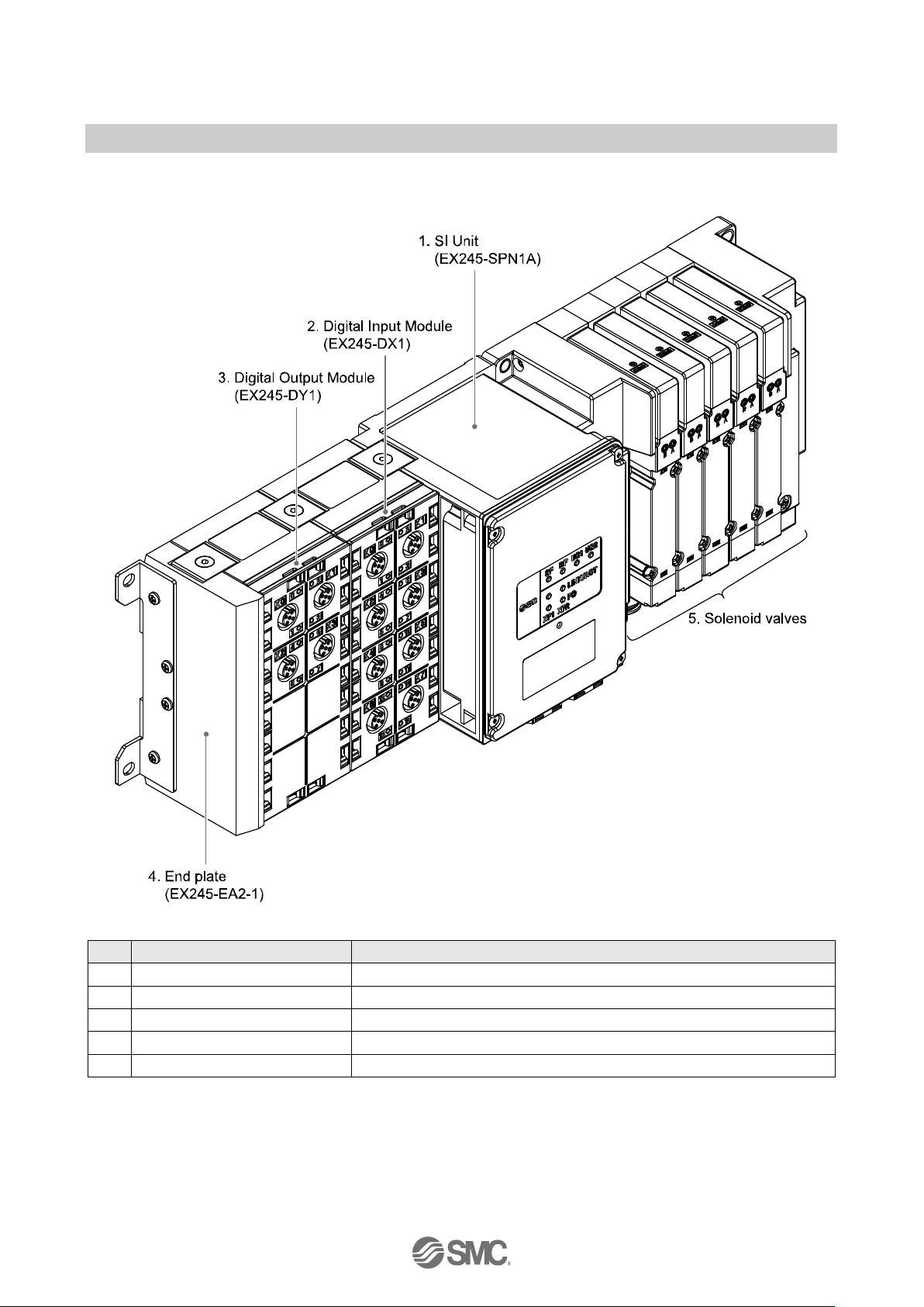
1.2. Structure
No.
Components
Function
1
SI Unit
Fieldbus, valve interface and supply voltage to modules
2
Digital Input Module
Supply voltage to sensors and input digital data
3
Digital Output Module
Output to electric loads
4
End plate
End plate of module side
5
Solenoid valves
Operate pneumatic devices
Fig. 1-1 System structure
Page 12

- 12 -
No.EX※※-OMW0011-A
2. General Specifications
Table. 2-1 EX245 series general specifications
Item
Specification
Rated voltage
24 V DC
Allowable instantaneous
electrical stop
1 msec maximum
Protection class
IP65 rating (when fully installed or fitted with protective cover)
(complies with IEC 60529)
Applicable standard
CE Marked
RoHS directive EN50581:2012
Withstand voltage
500 VAC 1 min. (between FE and all accessible terminals)
Insulation resistance
10 M ohm or more
(500 V DC is given between FE and all accessible terminals)
Ambient temperature
Operation: -10 °C to 50 °C
Storage: -20 °C to 60 °C
Ambient humidity
35% to 85% RH (non-condensing)
Vibration resistance
10 Hz to 57 Hz (constant amplitude) 0.75 mm
57 Hz to 150 Hz (constant acceleration) 49 m/s2
2 hours for each direction X, Y and Z
Impact resistance
147 m/s2 is given 3 times for each direction X, Y and Z
Operating environment
No corrosive gas
Page 13
- 13 -
No.EX※※-OMW0011-A
3. Installation
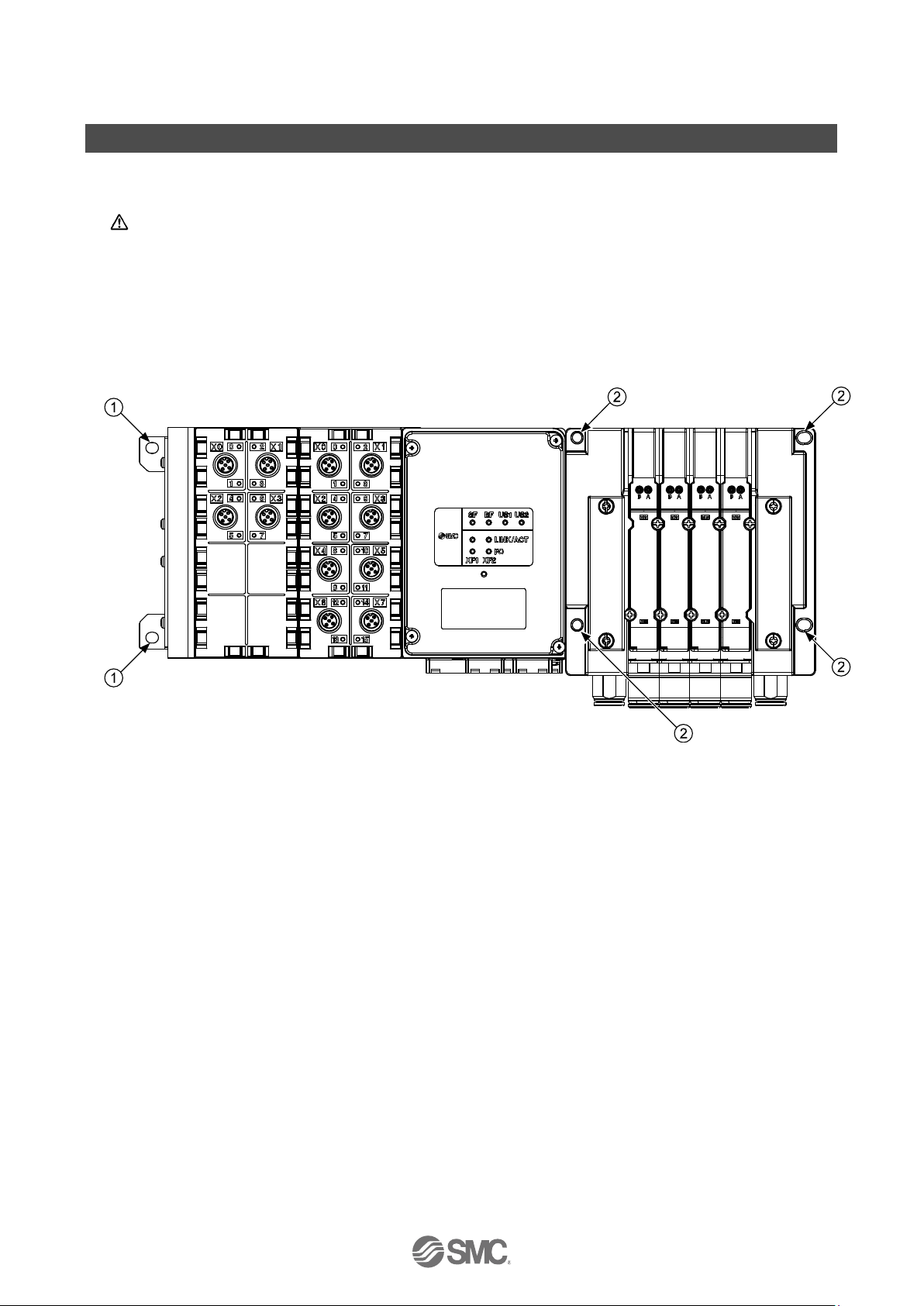
3.1. Mounting
Caution
To prevent manifold components being damaged, apply the recommended tightening torque.
Mount the manifold using the 6 mounting positions on the base with screws.
Required screws are as follows:
① 2 x M5 (End plate: torque = 1.5 Nm)
② 4 x M* (Valve manifold: refer to valve manifold catalogue)
Fig. 3-1 Required screws
All manifolds are mounted using 6 screws (except VQC4000 which uses 5 screws).
Page 14
- 14 -
No.EX※※-OMW0011-A
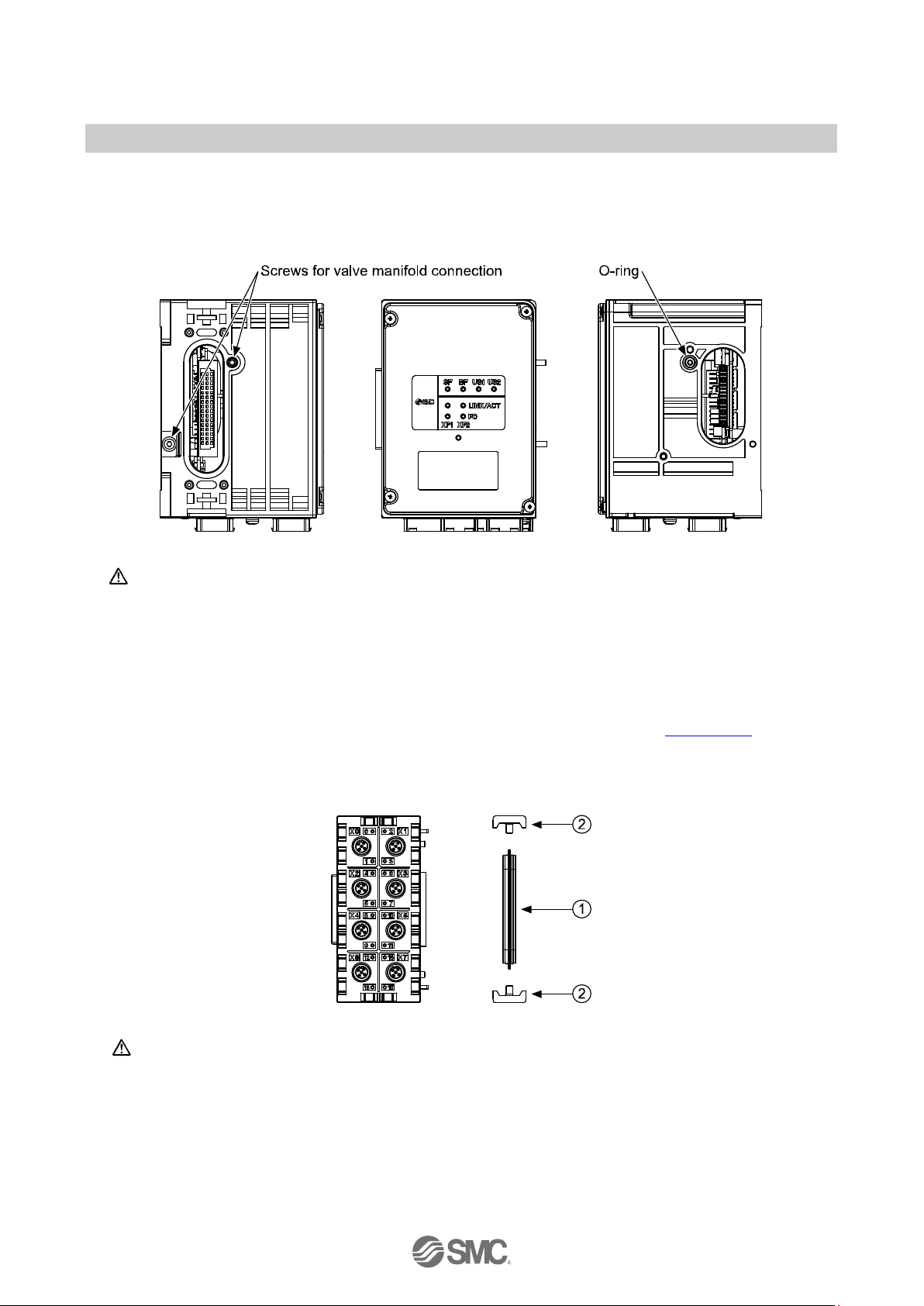
3.1.1. Valve manifold connection
Connect the valve manifold with the 2 screws on the SI Unit. (hexagonal socket wrench size 2.5)
For torque value, refer to valve manifold catalogue.
Fig. 3-2 Valve manifold connection
Caution
For a protection rating of IP65 to be ensured, apply the recommended tightening torque and make
sure that the O-ring is positioned correctly on the screw.
3.1.2. Module connection
Connect the SI Unit, the Input/Output modules and the End plate with the 2 modular adaptor assemblies
and a joint assembly. These are grouped together in the Joint pack, refer to the Section 10.4.
① 1 x Joint assembly
② 2 x Modular adaptor assembly (hexagonal socket wrench size 2.5, torque = 1.3 Nm)
Fig. 3-3 Module connection
Caution
・ For a protection rating of IP65 to be maintained, the End plate must be installed on the end of
module side correctly.
・ For a protection rating of IP65 to be ensured, modular adaptor assemblies and joint assembly
must be installed between each module correctly.
・ To prevent the modules and assemblies being damaged, apply the recommended tightening
torque.
Page 15
- 15 -
No.EX※※-OMW0011-A
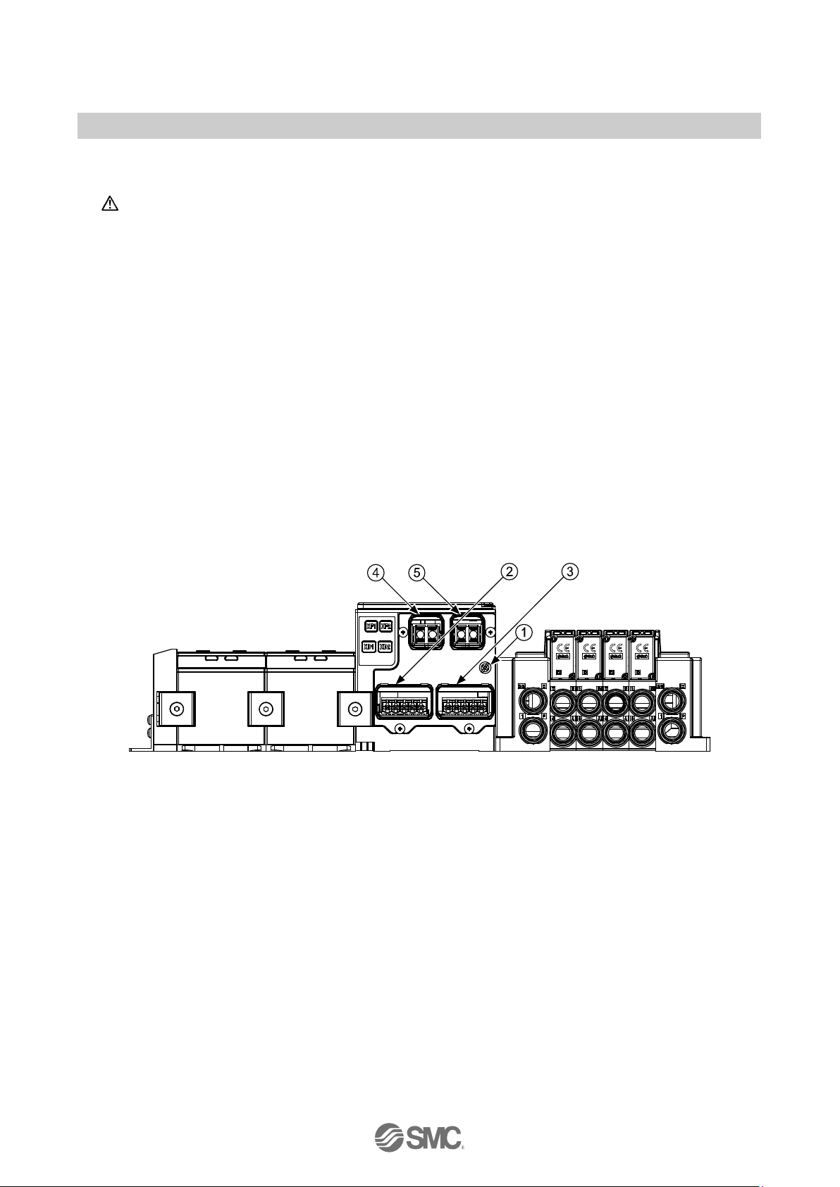
3.2. Wiring
Caution
To prevent damage, all voltages to the SI Unit must be turned off (i.e. de-energized) before the
modules are installed or removed.
Wire the grounding cable, the PROFINET cables and the power cable.
EX245-SPN1A
① M4, FE terminal screw (torque = 0.7 - 0.8 Nm)
② Push Pull connector (24 Volt), Power connection (XD1)
③ Push Pull connector (24 Volt), Power connection (XD2)
④ Push Pull connector (SCRJ), PROFINET connection Port1 (XF1)
⑤ Push Pull connector (SCRJ), PROFINET connection Port2 (XF2)
EX245-SPN2A
① M4, FE terminal screw (torque = 0.7 - 0.8 Nm)
② Push Pull connector (24 Volt), Power connection (XD1)
③ Push Pull connector (24 Volt), Power connection (XD2)
④ Push Pull connector (RJ45), PROFINET connection Port1 (XF1), Port type: MDI
⑤ Push Pull connector (RJ45), PROFINET connection Port2 (XF2), Port type: MDI-X
Fig. 3-4 Screw and connector allocation (EX245-SPN1A/SPN2A)
Page 16
- 16 -
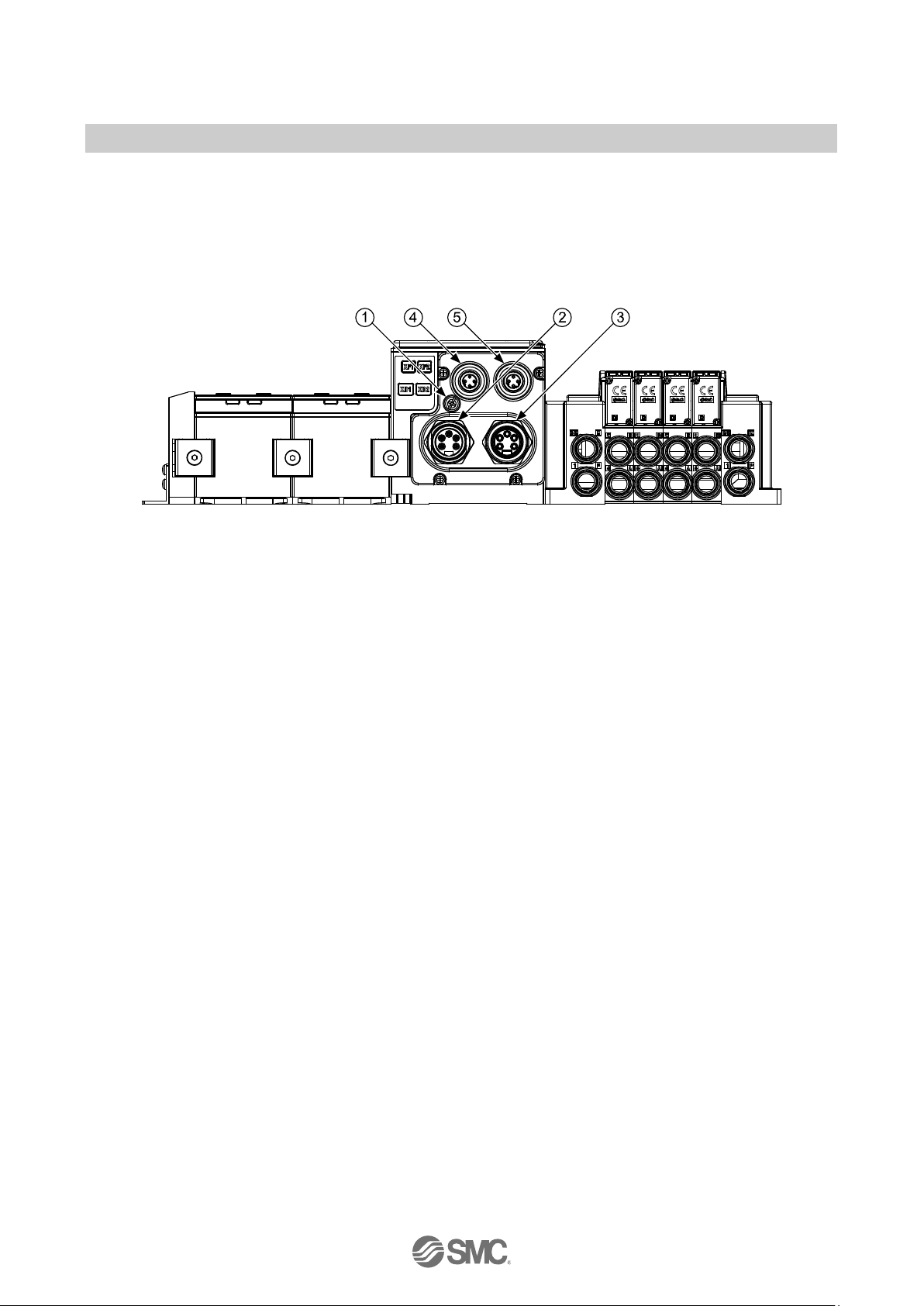
No.EX※※-OMW0011-A
EX245-SPN3A
① M4, FE terminal screw (torque = 0.7 - 0.8 Nm)
② 7/8 inch 5 pins plug connector, Power connection (XD1)
③ 7/8 inch 5 pins socket connector, Power connection (XD2)
④ M12 4 pins socket D-coded connector, PROFINET connection Port1 (XF1), Port type: MDI
⑤ M12 4 pins socket D-coded connector, PROFINET connection Port2 (XF2), Port type: MDI-X
Fig. 3-5 Screw and connector allocation (EX245-SPN3A)
Page 17
- 17 -
No.EX※※-OMW0011-A
3.2.1. Power/Bus connection
The SI Unit has two Power connectors (XD1/XD2) and two PROFINET communication
connectors (XF1/XF2). If only one connector is used, cover the unused connector with a seal cap so
that the protection rating of IP65 is maintained.
The supply for the logic/sensors “US1” and the supply for the valves/loads “US2” provide the
connected modules and the valve coils via the SI Unit.
The two supplies are isolated electrically and can be switched independently.
Caution
・ Seal caps must be fitted to all unused bus & power connector ports to ensure an IP65 rating.
・ Seal caps must be fitted to all unused bus connector ports to prevent eye exposure to the light
beam from the SCRJ connectors for the EX245-SPN1A
・ Power and bus lines must be installed correctly.
・ To prevent manifold components of the SI Unit from being damaged the supply lines for the
electronics and for the load voltage must be protected externally with a fuse.
・ Maximum loop through current between power connectors on each SI Unit must not be
exceeded.
・ The EX245-SPN1A makes use of a CLASS 1 LASER product. Do not stare into beam visible at
XF1/XF2.
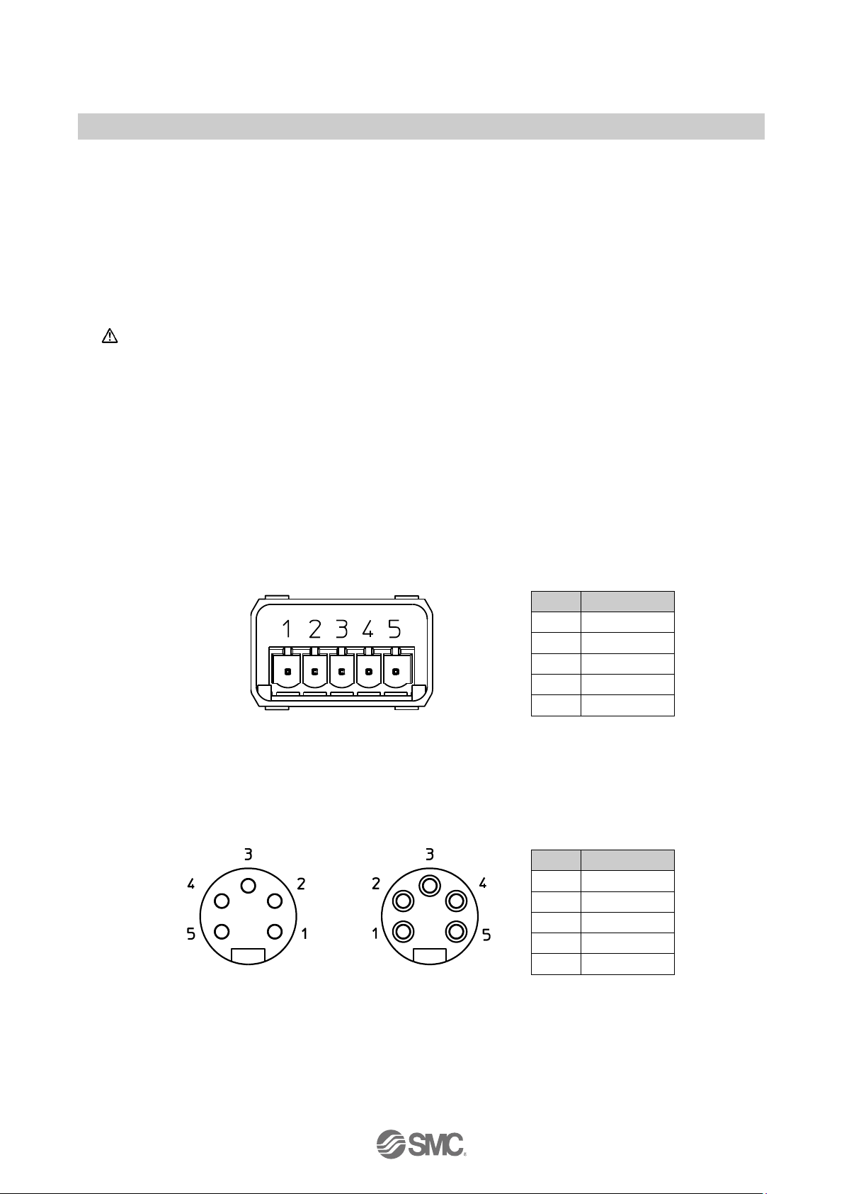
Power connectors
Pin
Remarks
1
24V (US1)
2
0V (US1)
3
24V (US2)
4
0V (US2)
5
FE
View of Push Pull
connector (XD1/XD2)
Fig. 3-6 Pin allocation of Push Pull connector (24 Volt) for EX245-SPN1A/SPN2A
Pin
Remarks
1
0V (US2)
2
0V (US1)
3
FE 4 24V(US1)
5
24V(US2)
View of 7/8 inch 5 pins
plug connector (XD1)
View of 7/8 inch 5 pins
socket connector (XD2)
Fig. 3-7 Pin allocation of 7/8 inch 5 pins connector for EX245-SPN3A
Page 18
- 18 -
No.EX※※-OMW0011-A
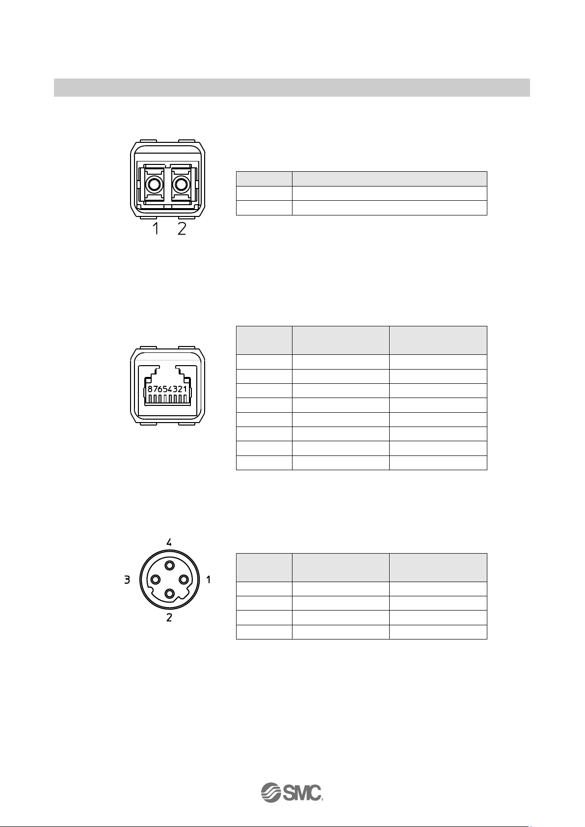
PROFINET communication connectors
Pin
Port1/Port2
1
TX Transmit Data
2
RX Receive Data
View of Push Pull
connector (XF1/XF2)
Fig. 3-8 Pin allocation of Push Pull connector (SCRJ) for EX245-SPN1A
Pin
Port1 (XF1)
Port type: MDI
Port2 (XF2)
Port type: MDI-X
1
TD+ Transmit data+
RD+ Receive data+
2
TD- Transmit data-
RD- Receive data-
3
RD+ Receive data+
TD+ Transmit data+
4 - -
5 - -
6
RD- Receive data-
TD- Transmit data-
View of Push Pull
connector (XF1/XF2)
7 - -
8 - -
Fig. 3-9 Pin allocation of Push Pull connector (RJ45) for EX245-SPN2A
Pin
Port1 (XF1)
Port type: MDI
Port2 (XF2)
Port type: MDI-X
1
TD+ Transmit data+
RD+ Receive data+
2
RD+ Receive data+
TD+ Transmit data+
3
TD- Transmit data-
RD- Receive data-
4
RD- Receive data-
TD- Transmit data-
View of M12 4 pins socket
D-coded connector
(XF1/XF2)
Fig. 3-10 Pin allocation of M12 4 pins socket D-coded connector for EX245-SPN3A
Page 19
- 19 -
No.EX※※-OMW0011-A
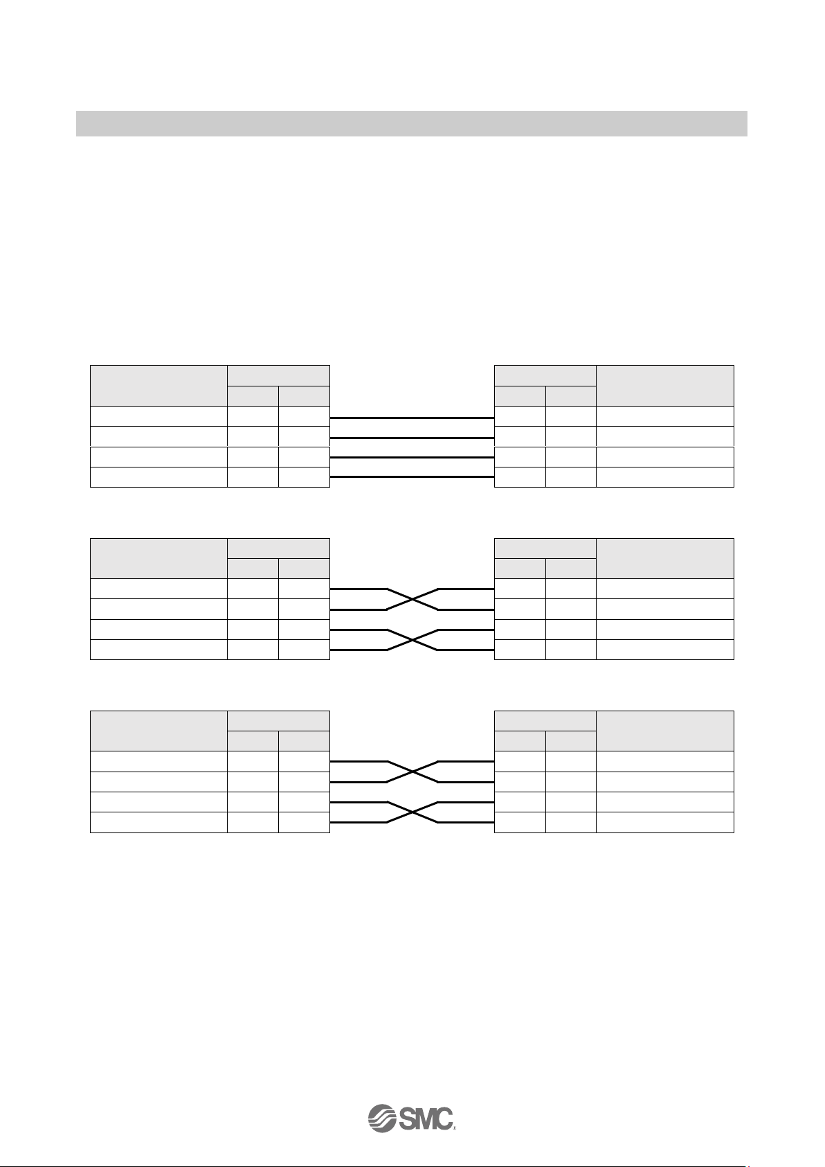
NOTE
・ When you use the EX245-SPN2A/EX245-SPN3A and the Autonegotiation function is disabled,
you must select the correct network cable, refer to Fig 3-11, 3-12.
・ Auto crossover function is not available when the Autonegotiation function is disabled.
・ Auto crossover function shall be capable of switching over their twisted pair ports automatically
between MDI and MDI-X pin assignment.
The following figure Fig. 3-11 shows examples on the use of two different cable types.
Patch cable
MDI
Pin Pin
MDI-X
RJ45
M12
RJ45
M12
TD+ Transmit data+
1 1 1 1
RD+ Receive data+
RD+ Receive data+
3 2 3 2
TD+ Transmit data+
TD- Transmit data-
2 3 2 3
RD- Receive data-
RD- Receive data-
6 4 6 4
TD- Transmit data-
Crossover cable
MDI
Pin Pin
MDI
RJ45
M12
RJ45
M12
TD+ Transmit data+
1 1 1 1
TD+ Transmit data+
RD+ Receive data+
3 2 3 2
RD+ Receive data+
TD- Transmit data-
2 3 2 3
TD- Transmit data-
RD- Receive data-
6 4 6 4
RD- Receive data-
Crossover cable
MDI-X
Pin Pin
MDI-X
RJ45
M12
RJ45
M12
RD+ Receive data+
1 1 1 1
RD+ Receive data+
TD+ Transmit data+
3 2 3 2
TD+ Transmit data+
RD- Receive data-
2 3 2 3
RD- Receive data-
TD- Transmit data-
6 4 6 4
TD- Transmit data-
Fig. 3-11 Patch and Crossover Cable details
Page 20
- 20 -
No.EX※※-OMW0011-A
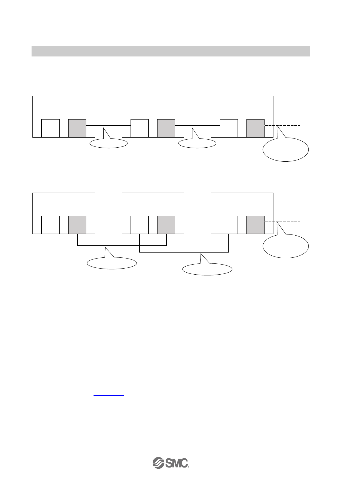
Connection example
Case 1
EX245-SPN2A/SPN3A
- Priorized startup (FSU)
- Disable Autonegotiation
Port 1
MDI
Port 2
MDI-X
Port *
MDI
Port #
MDI-X
Port 1
MDI
Port 2
MDI-X
IO controller or Switch
- Disable Autonegotiation
EX245-SPN2A/SPN3A
- Priorized startup (FSU)
- Disable Autonegotiation
Patch Cable
Patch Cable
Cable type
dependent upon
next port settings
Case 2
Port 2
MDI-X
Port 1
MDI
Port 2
MDI-X
IO controller or Switch
- Disable Autonegotiation
EX245-SPN2A/SPN3A
- Priorized startup (FSU)
- Disable Autonegotiation
EX245-SPN2A/SPN3A
- Priorized startup (FSU)
- Disable Autonegotiation
Port *
MDI
Port #
MDI-X
Port 1
MDI
Crossover Cable
Crossover Cable
Cable type
dependent upon
next port setti ngs
Fig. 3-12 Connection examples when using Disable Autonegotiation
3.2.2. FE terminal
The SI Unit must be connected to FE (Functional Earth) to divert electromagnetic interference. The
FE terminal and the FE pin of the two power connectors (XD1/XD2) are internally connected. Please
connect at least one of these three FEs to ground potential. For maximum protection the FE cable
should be as thick and short as reasonably possible. If it is difficult to shorten the power cable, it is
recommended to use the FE terminal screw.
3.2.3. Sensor/Load connection
Regarding the wiring of each module, refer to following section:
・ EX245-DX1 : Section 7.3
・ EX245-DY1 : Section 8.3
Page 21

- 21 -
No.EX※※-OMW0011-A
4. Commissioning
4.1. Configuration
The SI Unit is a modular station that consists of several modules. Setup your PROFINET IO
Controller’s software to reflect the configuration of your system.
4.1.1. GSD file and symbol files
In order to configure the SI Unit with your PROFINET IO Controller’s software the appropriate GSD
file is required. The GSD file contains all of necessary information to configure the SI Unit on your
PROFINET IO Controller’s software.
In order to represent the SI Unit in your PROFINET IO Controller’s software the appropriate symbol
files are required.
Current GSD file and symbol files name are as follows.
・ GSD file : GSDML-V2.3*-SMC-EX245-SPN-********.xml
・ Symbol files: GSDML-0083-0011-EX245.bmp
4.1.2. Head modules
The GSD file contains the description for two Head modules and three SI Units.
Table. 4-1 Head modules
Head module
Available SI Unit
EX245-SPN FX
EX245-SPN1A
EX245-SPN Cu
EX245-SPN2A
EX245-SPN3A
Page 22

- 22 -
No.EX※※-OMW0011-A
4.1.3. Modules
The SI Unit can consists of the following modules.
Table. 4-2 Overview of modules for the SI Unit
Module
Occupied bytes
Allowable slot
(Number / Name)
Note
Input
Output
Diagnostics type 1
4 bytes
-
1 / Diagnostics
Refer to the Section 5.1.1
Diagnostics type 1
shared
4 bytes
-
1 / Diagnostics
Refer to the Section 5.1.1
and Table 4-3
Diagnostics type 2
4 bytes
-
1 / Diagnostics
Refer to the Section 5.1.2
Diagnostics type 2
shared
4 bytes
-
1 / Diagnostics
Refer to the Section 5.1.2
and Table 4-3
16 Valves
-
2 bytes
2 / Valves
Refer to the Section 6.3
16 Valves shared
-
2 bytes
2 / Valves
Refer to the Section 6.3
and Table 4-3
32 Valves
-
4 bytes
2 / Valves
Refer to the Section 6.3
32 Valves shared
-
4 bytes
2 / Valves
Refer to the Section 6.3
and Table 4-3
EX245-DX1
2 bytes
-
3..10 / module 1..8
Refer to the Section 7.4
EX245-DX1 shared
2 bytes
-
3..10 / module 1..8
Refer to the Section 7.4
and Table 4-3
EX245-DY1
-
1 byte
3..10 / module 1..8
Refer to the Section 8.4
EX245-DY1 shared
-
1 byte
3..10 / module 1..8
Refer to the Section 8.4
and Table 4-3
4.1.4. Sub modules
Using the module named as “shared”, other PROFINET IO Controllers can use the copied input data
in the sub modules.
Table. 4-3 Overview of Sub modules for the SI Unit
Sub module
Occupied input bytes
Bytes to be copied
Diagnostics type 1
shared
4 bytes
4 bytes input data for diagnostics.
Refer to the Section 5.1.1.
Diagnostics type 2
shared
4 bytes
4 bytes input data for diagnostics.
Refer to the Section 5.1.2
16 Valves shared
2 bytes
2 bytes output data for valve outputs.
Refer to the Section 6.3
32 Valves shared
4 bytes
4 bytes output data for valve outputs.
Refer to the Section 6.3
EX245-DX1 shared
2 bytes
2 bytes input data for EX245-DX1 inputs.
Refer to the Section 7.4
EX245-DY1 shared
1 byte
1 byte output data for EX245-DY1 outputs.
Refer to the Section 8.4
Page 23

- 23 -
No.EX※※-OMW0011-A
4.1.5. Configuration steps
Enter the modules in your configuration program corresponding to the actual module layout and a
"Diagnostics type" module if required (Refer to the Section 5.1). If the configuration does not match
the actual layout, the connection to the IO Controller will not be established.
Configuration steps:
・ When using the EX245-SPN1A, choose the Head module “EX245-SPN FX” on the
configuration software. When using the EX245-SPN2A/EX245-SPN3A, choose the Head
module “EX245-SPN Cu”.
・ Enter the "Diagnostics type 1/2" modules in Diagnostics slot if required.
・ Enter the "16/32 Valves" module in Valves slot if use valves.
・ Enter the modules “EX245-DX1” and “EX245-DY1” in each module slot if modules are
connected (max. 8 modules).
Example of a configuration
Slot name
Actual module
Configuration module
Input bytes
Output bytes
Diagnositics
-
Diagnostics type 1
4
-
Valves
4 x Double solenoid
Valves
16 Valves - 2
Module 1
EX245-DX1
EX245-DX1
2
-
Module 2
EX245-DX1
EX245-DX1
2
-
Module 3
EX245-DX1
EX245-DX1
2
-
Module 4
EX245-DY1
EX245-DY1
-
1
Module 5
EX245-DY1
EX245-DY1
-
1
Fig. 4-1 Example of assignment of modules
Diagnostics slot
Diagnostics type 1
Page 24

- 24 -
No.EX※※-OMW0011-A
4.2. Parameterisation
4.2.1. Module parameters
・ Module parameters for valves
The "16 Valves" has the following module parameters.
Table. 4-4 Module parameters of the “16 Valves”
Name
Range of values
Default
Meaning
Valve Output 0
Force to OFF
Force to ON
Hold last state
Force to OFF
When a bus fault occurs, the output
can be made to react in one of the
following ways:
Force to OFF
Force to ON
Hold last state
Valve Output 1
Force to OFF
Force to ON
Hold last state
Force to OFF
… … …
Valve Output 15
Force to OFF
Force to ON
Hold last state
Force to OFF
The "32 Valves" has the following module parameters.
Table. 4-5 Module parameters of the “32 Valves”
Name
Range of values
Default
Meaning
Valve Output 0
Force to OFF
Force to ON
Hold last state
Force to OFF
When a bus fault occurs, the output
can be made to react in one of the
following ways:
Force to OFF
Force to ON
Hold last state
Valve Output 1
Force to OFF
Force to ON
Hold last state
Force to OFF
… … …
Valve Output 31
Force to OFF
Force to ON
Hold last state
Force to OFF
Page 25

- 25 -
No.EX※※-OMW0011-A
・ Module parameters for EX245-DX1
The EX245-DX1 has the following module parameter.
Table. 4-6 Module parameter of “EX245-DX1”
Name
Range of values
Default
Meaning
Input filter
Enable
Disable
Enable
Sets the time to ignore the input signal
change per module as follows:
Enable : 8 msec
Disable : No input filter
・ Module parameters for EX245-DY1
The EX245-DY1 has the following module parameters.
Table. 4-7 Module parameters of “EX245-DY1”
Name
Range of values
Default
Meaning
Digital Output 0
Force to OFF
Force to ON
Hold last state
Force to OFF
When a bus fault occurs, the output can
be made to react in one of the following
ways:
Force to OFF
Force to ON
Hold last state
Digital Output 1
Force to OFF
Force to ON
Hold last state
Force to OFF
… … …
Digital Output 7
Force to OFF
Force to ON
Hold last state
Force to OFF
Page 26

- 26 -
No.EX※※-OMW0011-A
4.2.2. Energy saving mode for PROFIenergy
Each module has the following module parameters for PROFIenergy.
The SI Unit starts the energy saving mode when the SI Unit receives the PROFIenergy command.
Regarding the LED indicator during energy saving mode, refer to the Section 6.4.6.
Table. 4-8 PROFIenergy parameters of “16/32 Valves”
Parameters
Range of values
Explanation
Valves supply
Output value
Valves output
operation at pause
Proceed
ON
Depending on valves behavior
Force to OFF
(Default)
OFF
Fixed 0x00
Hold last status
Hold last value
Table. 4-9 PROFIenergy parameters of “EX245-DX1”
Parameters
Range of
values
Explanation
Switch/sensor
supply
Input value
LED indicator of EX245-DX1
Sensor supply
and input value at
pause
Proceed
ON
Depending on
switch/sensor
behavior
Depending on switch/sensor
behavior
Shut down,
Clear value
(Default)
OFF
Fixed 0x00
OFF
Shut down,
Hold last
status
Hold last value
Table. 4-10 PROFIenergy parameters of “EX245-DY1”
Parameters
Range of
values
Explanation
Load supply
Output value
LED indicator of EX245-DY1
Digital output
operation at
pause
Proceed
ON
Depending on
load behavior
Depending on load behavior
Force to OFF
(Default)
OFF
Fixed 0x00
OFF
Hold last
status
Hold last value
Page 27

- 27 -
No.EX※※-OMW0011-A
5. Diagnosis
5.1. Diagnostics data on I/O mapping
The SI Unit can be allocated diagnostics data as digital input data on I/O mapping, if one of the
module, Diagnostics type 1 or Diagnostics type 2, is configured. Use PROFINET IO Controller’s
software to select a requested diagnostics type to allocate the diagnostics data on I/O mapping.
5.1.1. Diagnostics type 1
Table. 5-1 Overview of Diagnostics type 1
Byte
Description
0
General diagnostics 1
1
General diagnostics 2
2
Valve diagnostics 1
3
Valve diagnostics 2
・ General diagnostics 1
Table. 5-2 General diagnostics 1
Bit
Description
Explanation
0
System fault
0: No error on Diagnostics data on I/O mapping
1: At least one error on Diagnostics data on I/O mapping has occurred
1
Valve-coil(s) short circuit
0: No valve coil(s) have a short circuit
1: At least one valve coil has a short circuit
2
Module error
0: No module has an error
1: At least one connected module has an error
3
Changed module layout
0: Module has not disconnected.
1: At least one module has disconnected.
4
US1 Diagnostics
0: US1 present
1: US1 has dropped (< approx. 19.2V DC)
5
Reserved
Fixed 0
6
Reserved
Fixed 0
7
Reserved
Fixed 0
Page 28

- 28 -
No.EX※※-OMW0011-A
・ General diagnostics 2
Table. 5-3 General diagnostics 2
Bit
Description
Explanation
0
Module 1 error
0: No error or not connected, 1: Module 1 has an error
1
Module 2 error
0: No error or not connected, 1: Module 2 has an error
2
Module 3 error
0: No error or not connected, 1: Module 3 has an error
3
Module 4 error
0: No error or not connected, 1: Module 4 has an error
4
Module 5 error
0: No error or not connected, 1: Module 5 has an error
5
Module 6 error
0: No error or not connected, 1: Module 6 has an error
6
Module 7 error
0: No error or not connected, 1: Module 7 has an error
7
Module 8 error
0: No error or not connected, 1: Module 8 has an error
・ Valve diagnostics 1
Table. 5-4 Valve diagnostics 1
Bit
Description
Explanation
0
Valve 0, 1 diagnostics
0: No error, 1: Short circuit
1
Valve 2, 3 diagnostics
0: No error, 1: Short circuit
2
Valve 4, 5 diagnostics
0: No error, 1: Short circuit
3
Valve 6, 7 diagnostics
0: No error, 1: Short circuit
4
Valve 8, 9 diagnostics
0: No error, 1: Short circuit
5
Valve 10, 11 diagnostics
0: No error, 1: Short circuit
6
Valve 12, 13 diagnostics
0: No error, 1: Short circuit
7
Valve 14, 15 diagnostics
0: No error, 1: Short circuit
・ Valve diagnostics 2
Table. 5-5 Valve diagnostics 2
Bit
Description
Explanation
0
Valve 16, 17 diagnostics
0: No error, 1: Short circuit
1
Valve 18, 19 diagnostics
0: No error, 1: Short circuit
2
Valve 20, 21 diagnostics
0: No error, 1: Short circuit
3
Valve 22, 23 diagnostics
0: No error, 1: Short circuit
4
Valve 24, 25 diagnostics
0: No error, 1: Short circuit
5
Valve 26, 27 diagnostics
0: No error, 1: Short circuit
6
Valve 28, 29 diagnostics
0: No error, 1: Short circuit
7
Valve 30, 31 diagnostics
0: No error, 1: Short circuit
Page 29

- 29 -
No.EX※※-OMW0011-A
5.1.2. Diagnostics type 2
Table. 5-6 Overview of Diagnostics type 2
Byte
Description
0
General diagnostics 1
1
Valve diagnostics 1
2
General diagnostics 2
3
Valve diagnostics 2
・ General diagnostics 1
Table. 5-7 General Diagnostics 1
Bit
Description
Explanation
0
Maximum number of valves
0: 16 Valves
1: 32 Valves or no “Valves” module
1
Valve coil(s) short circuit
0: No valve coil(s) have a short circuit
1: At least one valve coil has a short circuit
2
US1 diagnostics 1
0: US1 present
1: US1 has dropped (< approx. 19.2 V DC)
3
Reserved
Fixed 0
…
… … 7
Reserved
Fixed 0
・ Valve diagnostics 1
Table. 5-8 Valve diagnostics 1
Bit
Description
Explanation
0
Valve 0, 1 diagnostics
0: Short circuit, 1: No error
1
Valve 2, 3 diagnostics
0: Short circuit, 1: No error
2
Valve 4, 5 diagnostics
0: Short circuit, 1: No error
3
Valve 6, 7 diagnostics
0: Short circuit, 1: No error
4
Valve 8, 9 diagnostics
0: Short circuit, 1: No error
5
Valve 10, 11 diagnostics
0: Short circuit, 1: No error
6
Valve 12, 13 diagnostics
0: Short circuit, 1: No error
7
Valve 14, 15 diagnostics
0: Short circuit, 1: No error
Page 30

- 30 -
No.EX※※-OMW0011-A
・ General diagnostics 2
Table. 5-9 General diagnostics 2
Bit
Description
Explanation
0
Module 1 diagnostics
0: No error or not connected, 1: Module 1 has an error
1
Module 2 diagnostics
0: No error or not connected, 1: Module 2 has an error
2
Module 3 diagnostics
0: No error or not connected, 1: Module 3 has an error
3
Module 4 diagnostics
0: No error or not connected, 1: Module 4 has an error
4
Module 5 diagnostics
0: No error or not connected, 1: Module 5 has an error
5
Module 6 diagnostics
0: No error or not connected, 1: Module 6 has an error
6
Module 7 diagnostics
0: No error or not connected, 1: Module 7 has an error
7
Module 8 diagnostics
0: No error or not connected, 1: Module 8 has an error
・ Valve diagnostics 2
Table. 5-10 Valve diagnostics 2
Bit
Description
Explanation
0
Valve 16, 17 diagnostics
0: Short circuit, 1: No error
1
Valve 18, 19 diagnostics
0: Short circuit, 1: No error
2
Valve 20, 21 diagnostics
0: Short circuit, 1: No error
3
Valve 22, 23 diagnostics
0: Short circuit, 1: No error
4
Valve 24, 25 diagnostics
0: Short circuit, 1: No error
5
Valve 26, 27 diagnostics
0: Short circuit, 1: No error
6
Valve 28, 29 diagnostics
0: Short circuit, 1: No error
7
Valve 30, 31 diagnostics
0: Short circuit, 1: No error
Page 31

- 31 -
No.EX※※-OMW0011-A
5.2. Maintenance alarm for the Fibre-optic cables
When the strength margin of the Fibre-optic communication is not enough, the EX245-SPN1A
issues a "Maintenance alarm" for the Fibre-optic cable, if monitor setting of communication port is
enable.
If the FO LED of the EX245-SPN1A is flashing (more than 0 dB but less than 2 dB) or ON (the
margin is 0 dB), refer to the Section 6.4.5.
In order to recover from this alarm, please check in the following order.
Example
Step 1: Check/exchange ① the Fibre-optic cable.
Step 2: Check/exchange ② the previous device.
Step 3: Check/exchange ③ the EX245-SPN1A.
EX245-SPN1A
Port1
Port2
FO1: ON
Previous Device
Port
Next Device
Port
②
①
③
FO2: OFF
Page 32

- 32 -
No.EX※※-OMW0011-A
6. SI Unit
6.1. Parts and description
EX245-SPN1A
EX245-SPN2A
Fig. 6-1 Allocation of parts on the EX245-SPN1A/SPN2A
Page 33

- 33 -
No.EX※※-OMW0011-A
EX245-SPN3A
Fig. 6-2 Allocation of parts on the EX245-SPN3A
Page 34

- 34 -
No.EX※※-OMW0011-A
6.2. Specifications
Table. 6-1 Specifications
Item
Description
EX245-SPN1A
EX245-SPN2A
EX245-SPN3A
General
Dimensions (W x L x H) in mm
85 x 127.5 x 89.5
85 x 147.7 x 89.5
Weight
465 g
540 g
Housing materials
PBT
Maximum number of modules
8
Maximum number of digital inputs
128
Maximum number of digital outputs
64 (independent of solenoid valves)
Electrical
Internal current consumption
at 24 V DC (Via US1)
300 mA or less
200 mA or less
Protection against polarity reversal
Yes (US1 and US2)
Loop through current between power
connector
16 A or less
6 A or less *
US1
Operating voltage
24 V DC +20%/-15%
Under-voltage detection
Detected : < approx. 19.2 V DC
Max. current
6 A total
US2
Operating voltage
24 V DC +20%/-15%
Max. current
4 A
Voltage drop to valve supply
Max. 1.2 V at 24 V DC
Galvanic isolation
Yes (between US1 and US2)
Solenoid valve
Applicable series
JSY series
JSY3000, JSY5000
SY series
SY3000, SY5000
VQC series
VQC2000, VQC4000
Max. number of solenoid valves
32 solenoid coils
Load
Solenoid valve with surge voltage suppressor of 24 V DC,
1 W or less (SMC)
Output type of solenoid
Source/PNP (negative common)
Over current protection
Yes
Over current detection
Yes
NOTE
・ Maximum permissible current of 7/8 inch 5 pins plug connector is 10A.
So for example, the EX245-SPN3A can use 4A and a loop through current of 6A can be drawn
between connectors “XD1” and “XD2”
Page 35

- 35 -
No.EX※※-OMW0011-A
Table. 6-2 Specifications (continued)
Item
Description
EX245-SPN1A
EX245-SPN2A
EX245-SPN3A
Fieldbus
Bus protocol
PROFINET I/O
Conformance Class C
Yes (Only for IRT switch function)
FSU (Fast Start Up)
Yes
MRP (Media Redundancy Protocol)
Yes
MRPD (Media Redundancy for
Planned Duplication)
Yes
Shared device
Yes
PROFIenergy
Yes
Web server function
Yes
Firmware update
Yes
Net Load Class Ⅲ
Yes
Maintenance alarm for the Fibre-optic
cable
Yes
-
Vendor ID
0083h
Device ID
0011h
GSD file
GSDML-V2.3*-SMC-EX245-SPN-********.xml
Page 36

- 36 -
No.EX※※-OMW0011-A
6.3. Process data for valves
The SI Unit occupies 2 or 4 bytes of output data for valves. The counting of valve coils starts at the
SI Unit from left to right.
Byte
Output data
16 Valves
32 Valves
0
Valve coils 0-7
Valve coils 0-7
1
Valve coils 8-15
Valve coils 8-15
2
Valve coils 16-23
3
Valve coils 24-31
Fig. 6-3 The process data for valves
Page 37

- 37 -
No.EX※※-OMW0011-A
6.4. LED indicators
The LED indicators are arranged on the SI Unit as shown in the illustration below.
The layout of the LINK/ACT LEDs and FO LEDs are for port1 on the left side (XF1) and for port2 on
the right side (XF2).
EX245-SPN1A EX245-SPN2A/EX245-SPN3A
Designation
Description
Colour
SF
System fault
Red
BF
Bus fault
Red
US1
Supply for the logic/sensors
Green
US2
Supply for the valves/loads
Green
LINK/ACT
A combination of LINK LED and ACT LED
Connection status via Ethernet (LINK: Green)
Data exchange status (ACT: Orange)
Green/Orange
FO
Fibre-Optic communication diagnostics
Orange
Fig. 6-4 LED indicators of the SI Unit
Page 38

- 38 -
No.EX※※-OMW0011-A
6.4.1. SF and BF indicators
Table. 6-3 SF and BF indicators
SF
BF
Meaning
OFF
OFF
No fault (The SI Unit is currently exchanging data with the IO Controller without
errors).
ON
---
One of the following may have occurred.
・ US1 is below the permissible level (< approx. 19.2 V DC).
・ The valve coil has a short circuit or the connected module has a short circuit.
・ The connected module has disconnected.
---
ON
One of the following may have occurred.
・ The connection to the IO Controller is nothing, or disconnection to the IO
Controller.
・ Device name is not correct.
・ IP address is not set or not correct.
・ The GSD file is not correct.
・ The configuration data sent by the IO Controller does not match the actual
layout.
Alternately flash
at 1 Hz
One of the following may have occurred.
・ During firmware update.
・ During forced output mode by Web server function.
Simultaneously flash
at 1 Hz
Firmware update failed.
6.4.2. US1 indicator
Table. 6-4 US1 indicator
US1
Meaning
OFF
US1 is not present.
Flash at 1 Hz
US1 is present but is below the permissible level (< approx. 19.2 V DC).
ON
US1 is present.
6.4.3. US2 indicator
Table. 6-5 US2 indicator
US2
Meaning
OFF
US2 is not present.
ON
US2 is present.
SF ON SF OFF
BF ON BF OFF
SF ON SF OFF
BF OFF BF ON
⇔
⇔
Page 39

- 39 -
No.EX※※-OMW0011-A
6.4.4. LINK/ACT indicator
Table. 6-6 LINK/ACT indicator
LINK/ACT
Meaning
Green ON
Connection via Ethernet to the SI Unit via Port 1/2 (XF1/XF2)
Green OFF
No connection established via Port 1/2 (XF1/XF2)
Orange ON
Transmission or reception of Ethernet telegrams on Port 1/2 (XF1/XF2)
Orange OFF
No transmission or reception of Ethernet telegrams on Port 1/2 (XF1/XF2)
Green Flash
at 1 Hz
Received node flash request
6.4.5. FO indicator
Table. 6-7 FO indicator
FO 1/2
Meaning
OFF
No fault.
The strength margin of the Fibre-optic communication is more than 2 dB on Port 1/2
(XF1/XF2).
Flash
at 1 Hz
The strength margin of the Fibre-optic communication is more than 0 dB but less than 2 dB on
Port 1/2 (XF1/XF2).
ON
The strength margin of the Fibre-optic communication is 0 dB on Port 1/2 (XF1/XF2).
NOTE
・ If monitor setting of communication port is enable, the FO indicator shows the status of the
maintenance alarm for the Fibre-optic cables, refer to the Section 5.2.
6.4.6. LED indicator during energy saving mode for PROFIenergy
Table. 6-8 LED indicator during energy saving mode for PROFIenergy
LED
Indicator
LINK/ACT
OFF
FO
OFF
SF
OFF
BF
OFF
US1
0.5 sec ON ⇔ 3 sec OFF
US2
OFF
NOTE
・ For module parameter of PROFIenergy, refer to the Section 4.2.2.
Page 40

- 40 -
No.EX※※-OMW0011-A
6.5. Block diagram
The following figure shows the block diagram of each SI Unit.
Fig. 6-5 Block diagram of the EX245-SPN1A
Page 41

- 41 -
No.EX※※-OMW0011-A
Fig. 6-6 Block diagram of the EX245-SPN2A
Page 42

- 42 -
No.EX※※-OMW0011-A
Fig. 6-7 Block diagram of the EX245-SPN3A
Page 43

- 43 -
No.EX※※-OMW0011-A
7. Digital Input Module - EX245-DX1
7.1. Parts and description
Fig. 7-1 Allocation of parts on the EX245-DX1
Page 44

- 44 -
No.EX※※-OMW0011-A
7.2. Specifications
Table. 7-1 EX245-DX1 specifications
Item
Description
General
Dimensions (W x L x H) in mm
54 x 120 x 61
Weight
265 g
Housing material
Nylon, PBT
Electrical
Rated supply voltage
24 V DC
Voltage drop to sensor supply
Max. 1.6 V
Internal current consumption at 24V DC
50 mA or less
Input connection type
8 x M12, 5 pins socket with double allocation
Over Voltage protection
Yes, more than 28 V DC at US1(sensor/input)
Over current protection
Yes
Sensor supply current per connector
Max. 0.5 A
Sensor supply current per module
Max. 2 A
Status indication
Yes, per input
Over current indication
Yes, per connector
Digital input
Number of inputs
16
Input type
PNP
Signal 1
11 to 30 V
Signal 0
-3 to 5 V
Permissible residual current
Max. 1.5 mA
Input current signal
Typ. 4.5 mA
Page 45

- 45 -
No.EX※※-OMW0011-A
7.3. Wiring
Caution
・ To prevent damage, all power for the SI Unit and modules must be turned off (i.e. de-energized)
before the modules are installed or removed.
・ For a protection rating of IP65 to be ensured, all covering caps must be screwed down correctly
after wiring and setting have been performed.
・ For a protection rating of IP65 to be ensured, sockets that are not used must be fitted with the
M12 Seal cap.
Pin allocation of the M12, 5 pins socket connector as shown in the following table:
Table. 7-2 Pin allocation of the connector for EX245-DX1
Pin
Allocation
View of connector (module side)
1
24 V 2
DI (input signal "n+1")
3
0 V (US1)
4
DI (input signal "n")
5
FE/Shield
7.4. Process data
The EX245-DX1 occupies 2 bytes of input data. The following table shows the allocation of the
digital inputs and the process image.
Table. 7-3 Digital input allocation and the process data
Connector position
Connector designation
X0
X1
X2
X3
X4
X5
X6
X7
Input
Pin 2
Bit 1
Bit 3
Bit 5
Bit 7
Bit 9
Bit 11
Bit 13
Bit 15
Pin 4
Bit 0
Bit 2
Bit 4
Bit 6
Bit 8
Bit 10
Bit 12
Bit 14
1 2 4
3
5
Page 46

- 46 -
No.EX※※-OMW0011-A
7.5. LED indicators
The status indicators are arranged on the EX245-DX1 as shown in the illustration below.
0 to15
Description
OFF
Input is not activated and no errors.
Green ON
Input is activated.
Red ON
Short circuit is detected.
Fig. 7-2 Status indicators of the EX245-DX1
Page 47

- 47 -
No.EX※※-OMW0011-A
7.6. Block diagram
The following figure shows the block diagram of the EX245-DX1.
Fig. 7-3 Block diagram of the EX245-DX1
Page 48

- 48 -
No.EX※※-OMW0011-A
8. Digital Output Module - EX245-DY1
8.1. Parts and description
Fig. 8-1 Allocation of parts on the EX245-DY1
Page 49

- 49 -
No.EX※※-OMW0011-A
8.2. Specifications
Table. 8-1 EX245-DY1 specifications
Item
Description
General
Dimensions (W x L x H) in mm
54 x 120 x 61
Weight
255 g
Housing material
Nylon, PBT
Electrical
Rated supply voltage
24 V DC
Voltage drop to load supply
Max. 1.6 V
Internal current consumption at 24 V DC
50 mA or less
Load connection
4 x M12, 5 pins socket with double allocation
Over Voltage protection
Yes, more than 28 V DC at US2(solenoid/output)
Over current protection
Yes
Output current per output
Max.0.5 A
Output current per module
Max.2 A
Status indication
Yes, per output
Over current indication
Yes, per output
Digital output
Number of outputs
8
Output type
PNP
Page 50

- 50 -
No.EX※※-OMW0011-A
8.3. Wiring
Caution
・ To prevent damage, all power for the SI Unit and modules must be turned off (i.e. de-energized)
before the modules are installed or removed.
・ For a protection rating of IP65 to be ensured, all covering caps must be screwed down correctly
after wiring and setting have been performed.
・ For a protection rating of IP65 to be ensured, sockets that are not used must be fitted with the
Seal cap.
Pin allocation of the M12, 5 pins socket connector as shown in the following table:
Table. 8-2 Pin allocation of the connector for EX245-DY1
Pin
Allocation
View of connector (module side)
1
N.C.
2 DO (output signal "n+1")
3
0 V (valves/loads)
4
DO (output signal "n")
5
FE/Shield
8.4. Process data
The EX245-DY1 occupies 1 byte of output data. The following table shows the allocation of the
digital outputs and the process image.
Table. 8-3 Digital output allocation and the process data
Connector position
Connector designation
X0
X1
X2
X3
Output
Pin 2
Bit 1
Bit 3
Bit 5
Bit 7
Pin 4
Bit 0
Bit 2
Bit 4
Bit 6
1 2 4 3 5
Page 51

- 51 -
No.EX※※-OMW0011-A
8.5. LED indicators
The status indicators are arranged on the EX245-DY1 as shown in the illustration below.
0 to 7
Description
OFF
Output is not activated and no errors.
Green ON
Output is activated.
Red ON
Short circuit is detected.
Fig. 8-2 Status indicators of the EX245-DY1
Page 52

- 52 -
No.EX※※-OMW0011-A
8.6. Block diagram
The following figure shows the block diagram of the EX245-DY1.
Fig. 8-3 Block diagram of the EX245-DY1
Page 53

- 53 -
No.EX※※-OMW0011-A
9. End Plate - EX245-EA2-1/2/3/4/5
9.1. Parts and description
Fig. 9-1 Allocation of parts on the EX245-EA2-1
Fig. 9-2 Allocation of parts on the EX245-EA2-2
Page 54

- 54 -
No.EX※※-OMW0011-A
Fig. 9-3 Allocation of parts on the EX245-EA2-3
Fig. 9-4 Allocation of parts on the EX245-EA2-4
Page 55

- 55 -
No.EX※※-OMW0011-A
Fig. 9-5 Allocation of parts on the EX245-EA2-5
Page 56

- 56 -
No.EX※※-OMW0011-A
9.2. Specifications
Table. 9-1 EX245-EA2-1 specifications
Item
Description
Dimensions (W x L x H) in mm
28.6 x 120 x 61.5
Weight
120 g
Housing material
Nylon
Table. 9-2 EX245-EA2-2 specifications
Item
Description
Dimensions (W x L x H) in mm
14 x 120 x 61.5
Weight
85 g
Housing material
Nylon
NOTE
・ EX245-EA2-2 can be used to have a special bracket which must be assembled with 4
Cross-recessed head tapping screws (3x6, torque: 0.8±0.05 N•m)
Table. 9-3 EX245-EA2-3 specifications
Item
Description
Dimensions (W x L x H) in mm
27.6 x 120 x 61.5
Weight
120 g
Housing material
Nylon
Table. 9-4 EX245-EA2-4 specifications
Item
Description
Dimensions (W x L x H) in mm
28.6 x 160 x 61.5
Weight
150 g
Housing material
Nylon
Table. 9-5 EX245-EA2-5 specifications
Item
Description
Dimensions (W x L x H) in mm
27.6 x 120 x 61.5
Weight
120 g
Housing material
Nylon
Page 57

- 57 -
No.EX※※-OMW0011-A
10. Accessories
10.1. Markers
Markers are available in single sheets each containing 88 pieces,
For the EX245-DX1 and EX245-DY1 use the part No.EX600-ZT1.
Model No.:EX600-ZT1
Fig. 10-1 EX600-ZT1
Page 58

- 58 -
No.EX※※-OMW0011-A
10.2. Y Connector
Y connectors can be used with the EX245-DX1 and EX245-DY1.
There are two options –
2 x M12 to M12
2 x M8 to M12
Model No.:PCA-1557785
(Y branch Connector (2 x M12 to M12))
Fig. 10-2 PCA-1557785
Page 59

- 59 -
No.EX※※-OMW0011-A
Model No.:PCA-1557798
(Y branch Connector (2 x M8 to M12))
Fig. 10-3 PCA-1557798
Page 60

- 60 -
No.EX※※-OMW0011-A
10.3. Seal cap
Model No.: EX9-AWTS
(10 pieces for M12 socket connectors)
The EX9-AWTS can be used with the EX245-SPN3A, EX245-DX1 and EX245-DY1.
Mount the seal cap in the unused sockets.
IP65 rating is maintained by using the seal cap properly.
Fig. 10-4 EX9-AWTS
NOTE
・ Tighten the seal caps to the tightening torque specified (0.2N•m)
・ In case of the EX245-SPN3A, M12 Seal caps is fitted to PROFINET connection Port2 (XF2)
when shipped from factory.
Page 61

- 61 -
No.EX※※-OMW0011-A
Model No.:EX245-AWP
(10 pieces for Push Pull connectors of power connection)
The EX245-AWP can be used with the EX245-SPN1A/EX245-SPN2A.
Mount the seal cap in the unused connector.
IP65 rating is maintained by using the seal cap properly.
Fig. 10-5 EX245-AWP
Model No.:EX245-AWC
(10 pieces for Push Pull connectors of PROFINET connection)
The EX245-AWC can be used with the EX245-SPN1A/EX245-SPN2A.
Mount the seal cap in the unused connector.
IP65 rating is maintained by using the seal cap properly.
Fig. 10-6 EX245-AWC
NOTE
・ In case of the EX245-SPN1A or EX245-SPN2A, the Seal caps is fitted to all bus & power
connector when shipped from factory.
Page 62

- 62 -
No.EX※※-OMW0011-A
10.4. Joint pack
One "Joint assembly" and two "Modular adaptor assembly" are contained in one "Joint pack".
Model No.: EX245-ZJP
Joint assembly
Modular adaptor assembly
Fig. 10-7 EX245-ZJP
NOTE
・ One Joint pack is attached to the EX245-DX1, EX245-DY1 and EX245-EA2-1/2/3/4/5.
・ Regarding mounting, refer to the Section 3.1.2.
Page 63

- 63 -
No.EX※※-OMW0011-A
11. Dimensions
11.1. The Input/Output Modules Manifold
Fig. 11-1 Dimensions of the Modules manifold
NOTE
・ Fig. 11-1 shows when the EX245-EA2-1 is used.
The following table shows the length of the Input/Output Modules manifold.
Table. 11-1 Length the EX245-SPN1A/SPN2A/SPN3A manifold
n 0 1 2 3 4 5 6 7
8
L
113.6
167.6
221.6
275.6
329.6
383.6
437.6
491.6
545.6
Formulas: L = 54n + 113.6 (max. 8 modules) (Dimensions in mm)
Page 64

- 64 -
No.EX※※-OMW0011-A
12. Troubleshooting
12.1. EX245-SPN1A/SPN2A/SPN3A
Table. 12-1 Troubleshooting for bus communication
No.
Problem
Possible cause
Remedy
1
BF indicator is ON.
LINK indicator is OFF.
ACT indicator is OFF.
The SI Unit is not connecting to any
bus.
Check the cable connection.
2
BF indicator is ON.
LINK indicator is ON.
ACT indicator is ON.
The SI Unit is physically connected to
the IO Controller but the following
problem has occurred.
---
No bus communication.
Check the cable.
Connect to the PROFINET bus
communication.
The IO Controller is defective.
Check the IO Controller.
Device name is not correct.
Check the device names.
The GSD file is not correct.
Check the GSD file.
The configuration data sent by the IO
Controller does not match the actual
layout.
Configure the SI unit according to
the actual layout.
Table. 12-2 Troubleshooting for the problem with display on SF LED
No.
Problem
Possible cause
Remedy
1
SF indicator is ON.
US1 is below the permissible level
(< approx. 19.2 V DC).
Check the power supply.
The valve coil has a short circuit or the
connected module has a short circuit.
Check the solenoid valve for a
short circuit and the module
error/layout.
The connected module has
disconnected.
Check the connected module.
Table. 12-3 Troubleshooting for the problem with display on SF and BF LED
No.
Problem
Possible cause
Remedy
1
SF and BF indicators
are flashing alternately.
During firmware update.
---
During forced output mode by Web
server function.
---
2
SF and BF indicators
are flashing
simultaneously.
Firmware update failed.
Update the firmware again.
Page 65

- 65 -
No.EX※※-OMW0011-A
Table. 12-4 Troubleshooting for the problem with display on US1/US2 LED
No.
Problem
Possible cause
Remedy
1
US1 indicator is OFF.
Incorrect wiring.
Check the cable.
Check the wiring and pin numbers.
US1 is not present.
Check the supply for the
logic/sensors of the SI Unit.
2
US1 indicator is
flashing.
US1 is below the permissible level (<
approx. 19.2 V DC).
Check the supply for the
logic/sensors of the SI Unit.
3
US2 indicator is OFF.
Incorrect wiring.
Check the cable.
Check the wiring and pin numbers.
US2 is not present.
Check the supply for the
valves/loads.
Table. 12-5 Troubleshooting for malfunction of the solenoid valve
No.
Problem
Possible cause
Remedy
1
A solenoid valve is not
operating.
Incorrect mounting of valve manifold.
Check the mounting of the SI Unit
and valve manifold.
Solenoid valve is faulty.
Check the solenoid valve.
US2 is not present.
Check the supply for the valves.
Check the wiring and pin numbers.
Table. 12-6 Troubleshooting for the problem with display on FO LED
No.
Problem
Possible cause
Remedy
1
FO1 or FO2 indicator is
flashing.
The strength margin of the Fibre-optic
communication is more than 0 dB but
less than 2 dB on Port 1/2 (XF1/XF2).
Check the Fibre-optic cable.
2
FO1 or FO2 indicator is
ON.
The strength margin of the Fibre-optic
communication is 0 dB on Port 1/2
(XF1/XF2).
Check the Fibre-optic cable.
Page 66

- 66 -
No.EX※※-OMW0011-A
12.2. EX245-DX1
Table. 12-7 Troubleshooting for EX245-DX1
No.
Problem
Possible cause
Remedy
1
Signals cannot be
received even with
sensor.
Incorrect wiring.
Check the wiring and pin numbers.
US1 is not present.
Check the supply for the sensors.
Sensor is faulty.
Check the sensor.
2
Status indicator is red
ON.
“Pin 1: 24 V” and “Pin 3: 0 V” of the
sensor connection have over current.
Check the sensor.
Check the cable.
Check the wiring and pin numbers.
12.3. EX245-DY1
Table. 12-8 Troubleshooting for EX245-DY1
No.
Problem
Possible cause
Remedy
1
A load is not operating.
Incorrect wiring.
Check the wiring and pin numbers.
US2 is not present.
Check the supply for the loads.
Load is faulty.
Check the load.
2
Status indicator is red
ON.
“Pin 2/4: output signal” and “Pin 3: 0V”
of the load connection have over
current.
Check the load.
Check the cable.
Check the wiring and pin numbers.
Page 67

No.EX※※-OMW0011-A
Revision
A: Minor update (correction of sentences, etc.).
[March 2019]
4-14-1, Sotokanda, Chiyoda-ku, Tokyo 101-0021 JAPAN
Tel: + 81 3 5207 8249 Fax: +81 3 5298 5362
URL http://www.smcworld.com
Note: Specifications are subject to change without prior notice and any obligation on the part of the manufacturer.
© 2018-2019 SMC Corporation All Rights Reserved.
 Loading...