

SMC Networks EX230-SDN1 Installation And Maintenance Manual
Installation and Maintenance Manual
SI unit - DeviceNet compatible
Type EX230-SDN1
fety Instructions
• This manual contains essential information for the protection of users
and others from possible injury and/or equipment damage.
• Read this manual before using the product, to ensure correct handling,
and read the manuals of related apparatus before use.
• Keep this manual in a safe place for future reference.
• These instructions indicate the level of potential hazard by label of
"DANGER", "WARNING" or "CAUTION", followed by important safety
information which must be carefully followed.
• To ensure safety of personnel and equipment the safety instructions in
this manual and the product catalogue must be observed, along with
other relevant safety practices.
E
X230-TFK40GB-A
WARNING
• Do not disassemble, modify (including change of printed circuit
board) or repair the product.
An injury or product failure may result.
• Do not operate the product beyond the specification range.
Fire, malfunction or equipment damage may result. Use the product
only after confirming the specifications.
• Do not use the product in the presence of flammable, explosive or
corrosive gas.
Fire, explosion or corrosion may result. This product does not have an
explosion proof construction.
• When using the product as part of an interlocking system:
1) Provide a double interlocking system, for example a mechanical
system.
2) Check the product regularly to ensure proper operation.
• Before performing maintenance, be sure of the following:
1) Turn off the power supply.
2) Stop the air supply, exhaust the residual pressure and verify the
release of air from the system.
CAUTION
• Always perform a system check after maintenance.
Do not use the product if any error occurs.
Safety cannot be assured if caused by un-intentional malfunction.
• Provide grounding to ensure correct operation and to improve
noise resistance of the product.
This product should be individually grounded using a short cable.
• Follow the instructions given below when handling the product.
Failing to do so may result in product damage.
Maintenance space should always be provided around the product.
Do not remove labels from the product.
Do not drop, hit or apply excessive shock to the product.
Follow all specified tightening torques.
1 Safety Instructions (continued)
Do not bend, apply tensile force, or apply force by placing heavy loads,
on the cables.
Connect wires and cables correctly, and do not connect while the power
is ON.
Do not route wires and cables together with power or high-voltage
cables.
Check the insulation of wires and cables.
Take proper measures against noise, such as noise filters, when the
product is incorporated in equipment or devices.
Select the required protection (IP) rating according to the environment
of operation.
Take sufficient shielding measures when the product is to be used in the
following conditions:
(1) where noise due to static electricity is generated.
(2) where electro-magnetic field strength is high.
(3) where radioactivity is present.
(4) where power lines are located.
Do not use the product in a place where electric surges are generated.
Use suitable surge protection when a surge generating load such as a
solenoid valve is to be directly driven.
Prevent any foreign matter from entering this product.
Do not expose the product to vibration or impact.
Use the product within the specified ambient temperature range.
Do not expose the product to any heat radiation.
Use a precision screwdriver with flat blade to adjust the DIP switch.
Close the cover over the switches before power is applied.
Do not clean the product with chemicals such as benzene or thinners.
• Power Supply selection
A UL approved direct current (DC) power supply should be used with this
product, as follows:
1. A limited voltage / current supply in accordance with UL508.
A circuit from which power is supplied by the secondary coil of a
transformer according to the following:
Maximum voltage (no load) : Less than 30Vrms (42.4V peak)
Maximum current : (1) Less than 8A (including when short circuited)
(2) Limited by circuit protection (such as a fuse)
with the following rating.
2. A Class 2 power supply unit in accordance with UL1310, or a power
supply circuit of maximum 30Vrms (42.4V peak) or less, using a
Class 2 transformer in accordance with UL1585 as power source.
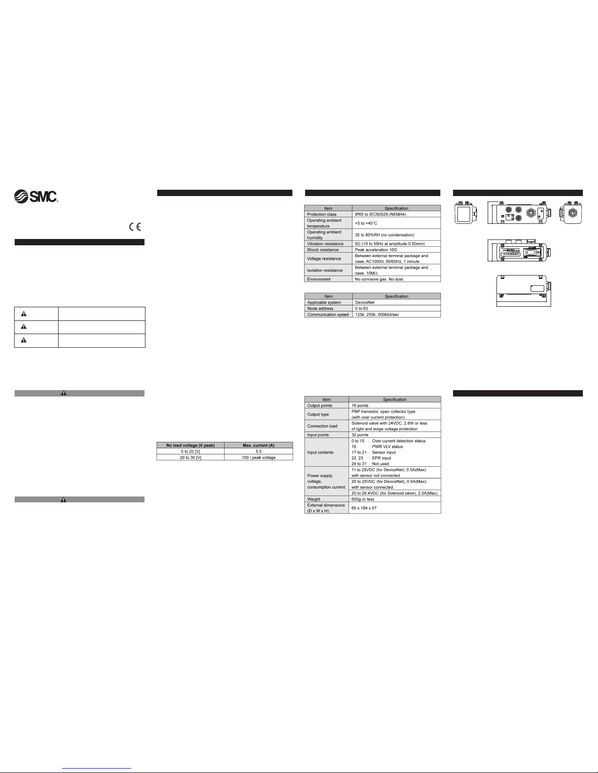
2 Specifications
General specifications
Communication specification
SI unit specification
4 Names / Functions of Individual Parts
• Input connector
To connect the sensors.
• Communication connector
To send and receive communication signals through DeviceNet line.
• Output equipment connector
To connect the output equipment such as a solenoid valve.
• Power supply connector for output equipment
To supply power to the output equipment such as a solenoid valve.
• Indication and address setting panel
To provide LED's to indicate the condition of the unit and the setting of
address, Hold / Clear functions and auto reset functions.
• Fuse
In the power supply for the sensor SI unit and output equipment, if an
over current flows because of short circuit etc., the power supply will be
disconnected by the fuse.
In this case, the user must fix the cause of the short circuit before
exchanging the fuse.
In extreme conditions, there is a possibility of
serious injury or loss of life.
WARNING
If instructions are not followed there is a
possibility of serious injury or loss of life.
CAUTION
If instructions are not followed there is a
possibility of injury or equipment damage.
3 Outline dimensions (mm)
EX230-SDN1EX230-SDN1
EX230-SDN1EX230-SDN1
TMTM
54
65
TMTM
65
54
67
152
57
65
54
164
DANGER
1 Safety Instructionsn All Rights Reserved.
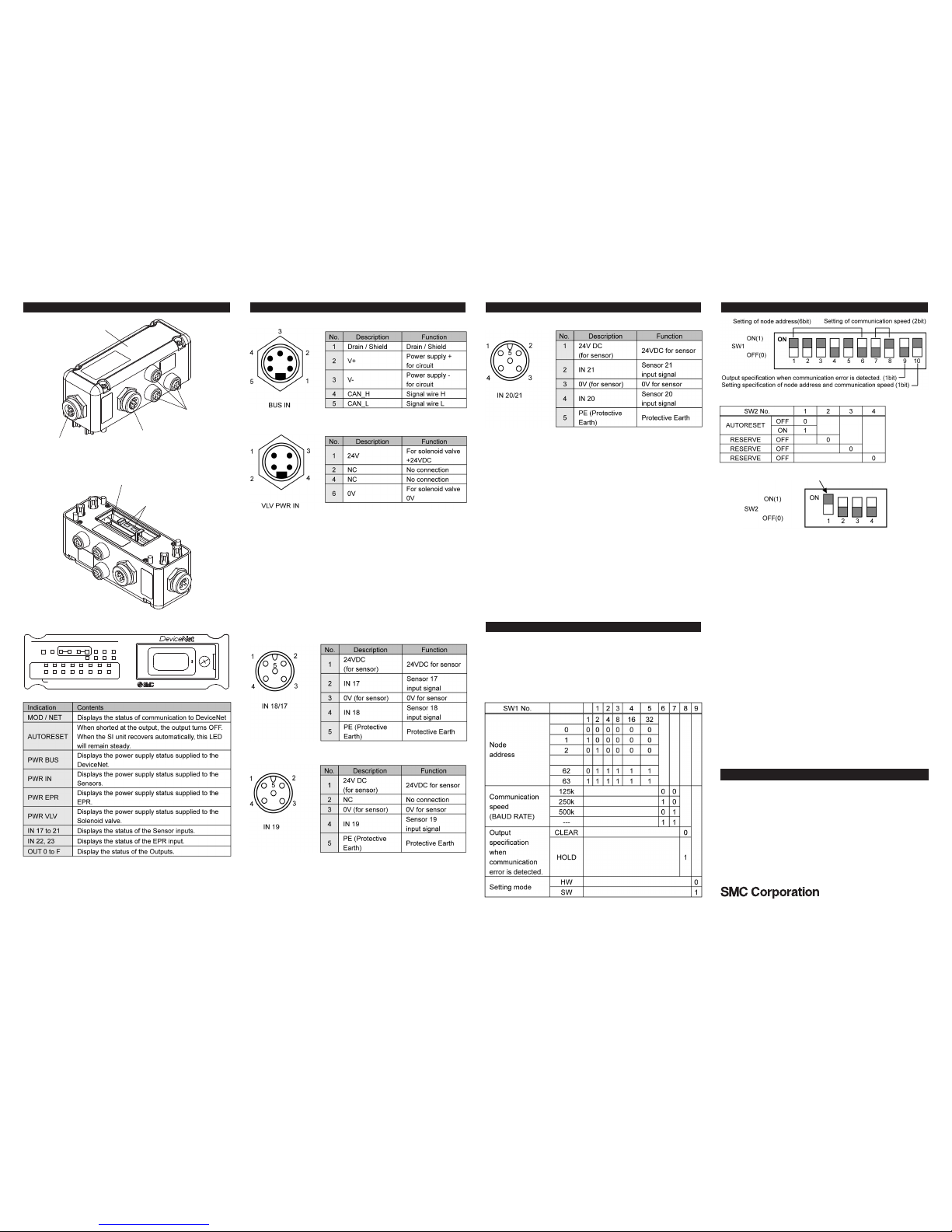
4 Names / Functions of Individual Parts (continued)
LED indication
5 Wiring
BUS connector specification
VLV PWR IN connector specification
Sensor connectors
Connector description : 5-pin connector (M12) Female
Connector description : 5-pin connector (M12) Female
5 Wiring (continued)
Connector description : 5-pin connector (M12) Female
6 Switch Setting
Address setting
When DIP switches are to be set, turn OFF power supply to SI unit.
2x DIP switches (SW1:10bit,SW2:4bit) are mounted under the display of the
SI unit.
To set switches, remove the fixing screw for the switch cover, open cover and
set each switch. Replace cover after setting.
How to set SW1
6 Switch Setting (continued)
How to set SW2
Setting of recovery from over current protection
E
X230-TFK40GB-A
Output equipment
connector
Fuse
SETTINGSSETTINGS
11
00
EX230-SDN1EX230-SDN1
TMTM
SERIAL UNITSERIAL UNIT
M
ODMOD
BUSBUS
0
0 11 22 33 44 55 66 77
88 99 1010 1111 1212 1313 1414 1515
AUTOAUTO
OUTOUT
IN16IN16
IN17IN17 IN18IN18 IN19IN19
I
N20IN20 IN21IN21 IN22IN22 IN23IN23
ININ EPREPRRESETRESET VLVVLV
F
LASHING:SHORT OUTPUT(DIAGNOSES IN 0-15)FLASHING:SHORT OUTPUT(DIAGNOSES IN 0-15)
PWRPWR
/
NET/NET
Indication and address
setting panel
Input connector
Communication connector
Power supply connector
for output equipment
AUSTRIA (43) 2262 62280 NETHERLANDS (31) 20 531 8888
BELGIUM (32) 3 355 1464 NORWAY (47) 67 12 90 20
CZECH REP.
(420) 541 424 611
POLAND (48) 22 211 9600
DENMARK (45) 7025 2900 PORTUGAL (351) 21 471 1880
FINLAND (358) 207 513513 SLOVAKIA (421) 2 444 56725
FRANCE (33) 1 6476 1000 SLOVENIA (386) 73 885 412
GERMANY (49) 6103 4020 SPAIN (34) 945 184 100
GREECE (30) 210 271 7265 SWEDEN (46) 8 603 1200
HUNGARY (36) 23 511 390 SWITZERLAND (41) 52 396 3131
IRELAND (353) 1 403 9000 UNITED KINGDOM (44) 1908 563888
ITALY (39) 02 92711
URL http://www.smcworld.com (Global) http://www.smceu.com (Europe)
Specifications are subject to change without prior notice from the manufacturer.
© SMC Corporation All Rights Reserved.
7 Contacts
 Loading...