

SMC Networks EX180-SDN4 Series, EX180-SDN3 Series, EX180-SDN5 Series, EX180-SDN6 Series Installation & Maintenance Manual
I
nstallation & Maintenance Manual
Fieldbus system - SI unit
Type EX180 Series for DeviceNet
TM
EX180-SDN3 /SDN4 /SDN5 /SDN6
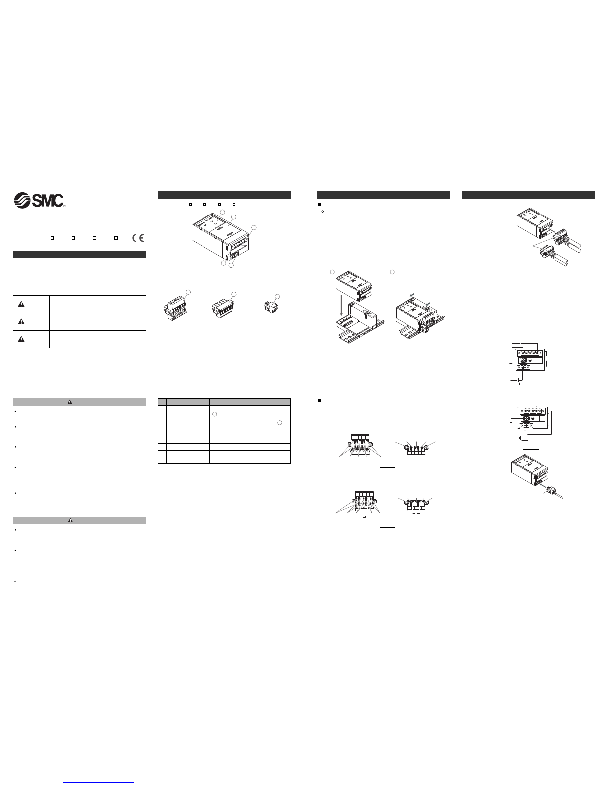
Fieldbus interface
connector (BUS)
Item Description
The connector for the DeviceNetTMbus line
( ).
6
Power supply
connector (PWR(V))
The connector for the power supply ( )
used to supply the power for the solenoid
valves.
7
FG terminal Functional Earth.
P
W
R
(
V
)
P
W
R
M
N
S
4
3
2
5
1
1
No.
2
3
Do not disassemble, modify (including changing the printed
circuit board) or repair.
An injury or failure can result.
Do not operate the product outside of the specifications.
Do not use for flammable or harmful fluids.
Fire, malfunction, or damage to the product can result.
Verify the specifications before use.
Do not operate in an atmosphere containing flammable or
explosive gases.
Fire or an explosion can result.
This product is not designed to be explosion proof.
If using the product in an interlocking circuit:
•Provide a double interlocking system, for example a mechanical
system.
•Check the product regularly for proper operation.
Otherwise malfunction can result, causing an accident.
The following instructions must be followed during maintenance:
•Turn off the power supply.
•Stop the air supply, exhaust the residual pressure and verify that the
air is released before performing maintenance.
Otherwise an injury can result.
S
afety Instructions
These safety instructions are intended to prevent hazardous situations
and/or equipment damage.
These instructions indicate the level of potential hazard with the labels of
"Caution", "Warning" or "Danger". They are all important notes for safety
and must be followed in addition to International standards (ISO/IEC)
and other safety regulations.
Warning
CAUTION indicates a hazard with a low level of risk
which, if not avoided, could result in minor or
moderate injury.
Caution
Warning
Danger
WARNING indicates a hazard with a medium level
of risk which, if not avoided, could result in death or
serious injury.
DANGER indicates a hazard with a high level of risk
which, if not avoided, will result in death or serious
injury.
Summary of Product Parts Installation
<EX180-SDN3 /SDN4 /SDN5 /SDN6 >
E
X180-TFO09
This product is class A equipment that is intended for use in an industrial
environment.
There may be potential difficulties in ensuring electromagnetic
compatibility in other environments due to conducted as well as radiated
disturbances.
NOTE
When conformity to UL is necessary the SI unit must be used with a UL
1310 Class2 power supply.
Caution
After maintenance is complete, perform appropriate functional
inspections.
Stop operation if the equipment does not function properly.
Safety cannot be assured in the case of unexpected malfunction.
Provide grounding to assure the safety and noise resistance of
the Fieldbus system.
Individual grounding should be provided close to the product with a
short cable.
Display LED diagnostic display.
Setting switches
Switches to set the MAC ID and
communication speed (inside the cover).
4
5
6
Communication connector for DeviceNetTM(1 pc.)
6
(EX180-CDN1)
(EX180-CDN2)
EX180-SDN3/4/5/6 EX180-SDN3A/4A/5A/6A
7
Power supply
connector (1 pcs.)
(EX180-CP1)
<Accessories>
General Instructions on Installation
Applicable valve series
The EX180 series SI unit can be mounted on the following valve
manifolds.
SJ2000/3000, S0700 series
∗: Refer to the catalogues and operation manuals for details of the solenoid
v
alves and manifolds.
•How to mount the manifold
1. Mount the SI unit to the manifold so that the mounting guide of the
SI unit case mates with the manifold groove.
2. Secure the SI unit using the two sliding locks.
P
W
R
(
V
)
P
W
R
M
N
S
P
W
R
(
V
)
P
W
R
M
N
S
1
2
Wiring
1. Wiring for communication
Wiring of the DeviceNetTMcommunication cable and connector is
shown below.
(1)Connect the signal wires to the assigned pins. (Figure 1)
The required tightening torque is 0.5 to 0.6 Nm.
V+
CAN_H
Drain
CAN_L
V-
White Drain Blue Black
Red
White Drain Blue
Black
Red
V+
CAN_H
Drain
CAN_L
V-
Installation (Continued)
Figure 1
(2)A bus termination is required at both ends of the
DeviceNetTMbus
segment as shown in Figure 2.
The specification of the terminating resistor is 121 Ω ±1%, 1/4 W.
V+
CAN_H
Drain
CAN_L
V-
Terminating resistor
White Drain Blue BlackRed
White Drain Blue BlackRed
V+
CAN_H
Drain
CAN_L
V-
Terminating resistor
Figure 2
(3)How to connect.
P
W
R
(
V
)
P
W
R
M
N
S
Communication connector
for DeviceNet
TM
Figure 3
2. Wiring of the power supply
Connect the power supply to the power supply connector (1 pc.).
The EX180 power supply structure consists of two supplies.
These supplies can be operated using a single or dual power supply
system.
Connect the wires to the assigned pins. (Figure 4, Figure 5)
The required tightening torque is 0.22 to 0.25 Nm.
•Note
Connect the FG terminal to ground with a ground resistance of
100 Ω or less.
DeviceNet
TM
power supply
24 VDC
Solenoid valve
power supply
24 VDC
24 VDC
Figure 4
A. Dual power supplies
B. Single power supply
P
W
R
(
V
)
P
W
R
M
N
S
Power supply connector
Figure 5
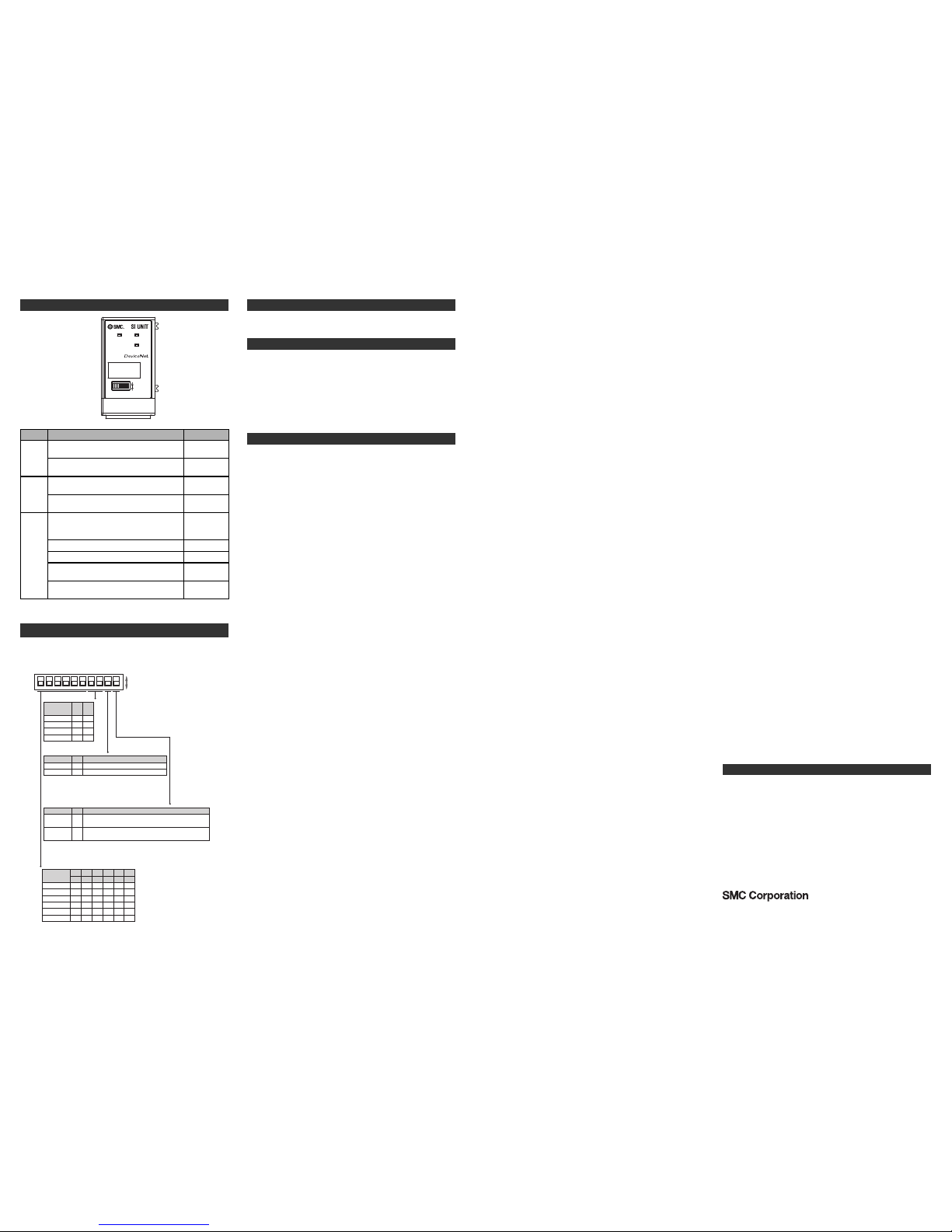
CLR
HOLD01
Clear all outputs.
Hold the last state before communication error.
::
The default setting is all switches ON, so the MAC ID is set to 63.
The MAC ID should be set in the range of 0 to 63.
500 kbps
Invalid
250 kbps
125 kbps
Communication
speed
0
1
1
0
No.7
1
1
0
0
No.8
Factory default setting is125 kbps.
Factory default setting is HW mode.
The MAC ID and communication speed will be retained if the unit is powered off and software mode
is selected (DIP switch 10).
If HW mode is selected then the settings stored using SW mode will be replaced by the HW settings.
1
1
0
0
0
1
1
0
0
0
:
1
1
0
0
0
32 16 8
::
1
1
0
0
0
1
1
1
0
0
:
0
1
0
0
1
421
No.1 No.2 No.3 No.4 No.5
#62
#63
:
#2
#0
MAC ID
setting
#1
No.6
1ON2345678910
1
DIP SW
0
C
ommunication speed setting
HOLD/CLR setting
01HW
SW/HW
SW
No.10
Setting of the MAC ID and communication speed can be carried out
using the DIP switches No.1 to 8.
Description
SW/HW mode setting
MAC ID setting
HOLD/CLR No.9 Description
Setting of the MAC ID and communication speed can be carried out
via the DeviceNet network. DIP switches No.1 to 8 will be invalid.
Factory default setting is CLEAR.
It is possible to set the output condition in the event of a communication
error individually via the DeviceNet
TM
network.
If the output condition is set via the DeviceNetTM Network then the setting
of DIP switch 9 is invalid.
E
X180-TFO09
Contacts
AUSTRIA (43) 2262 62280-0
NETHERLANDS (31) 20 531 8888
BELGIUM (32) 3 355 1464
NORWAY (47) 67 12 90 20
CZECH REP. (420) 541 424 611
POLAND (48) 22 211 9600 DENMARK (45) 7025 2900
PORTUGAL (351) 21 471 1880
FINLAND (358) 207 513513
SLOVAKIA (421) 2 444 56725 FRANCE (33) 1 6476 1000
SLOVENIA (386) 73 885 412GERMANY (49) 6103 4020
SPAIN (34) 945 184 100 GREECE (30) 210 271 7265
SWEDEN (46) 8 603 1200
HUNGARY (36) 23 511 390
SWITZERLAND (41) 52 396 3131 IRELAND (353) 1 403 9000
UNITED KINGDOM (44) 1908 563888
ITALY (39) 02 92711
URL http://www.smcworld.com (Global) http://www.smceu.com (Europe)
Specifications are subject to change without prior notice from the manufacturer.
© 2011 SMC Corporation All Rights Reserved.
BULGARIA (359) 2 974 4492
ESTONIA (372) 651 0370
ROMANIA (40) 21 320 5111
LATVIA (371) 781 77 00
LITHUANIA (370) 5 264 8126
Specification
Connected load: 24 VDC Solenoid valve with light and surge voltage
suppressor of 1 W or less (manufactured by SMC)
Current consumption of power supply for SI unit operation: 0.1 A max.
Ambient temperature for operation: -10 to 50 ℃
Ambient temperature for storage: -20 to 60 oC
Pollution degree 2: (UL508)
Refer to the SMC website (URL http://www.smcworld.com) for more
information about the product specifications.
Outline Dimensions
Refer to the SMC website (URL http://www.smcworld.com) for more
information about outline dimensions.
Troubleshooting
Refer to the SMC website (URL http://www.smcworld.com) for more
information about troubleshooting.
Setting of the DIP switches should only be carried out with the power
supply turned off.
Open the cover and set the DIP switches with a small flat blade screwdriver.
Setting
LED Display
PWR(V) PWR
MNS
DIP SW
1
ON
0
LED Description
MNS
Communication power supply for DeviceNet
TM
is OFF, off line or a MAC ID duplication is
present
PWR(V)
Solenoid valve power supply is supplied at the
specified voltage
PWR
Communication power supply for DeviceNet
TM
is supplied
Solenoid valve power supply is not supplied at
the specified voltage
I/O connection time out (Minor communication
error)
I/O connection is waiting (On line status)
I/O connection is established (On line status)
Communication power supply for DeviceNet
TM
is not supplied
MAC ID duplication error or BUS OFF error
(Serious communication error)
LED status
ON
OFF
Green flashing
Green ON
Red flashing
Red ON
ON
OFF
OFF
 Loading...