

SMC Networks EX120-SDN1-X26, EX120-SDN1-X77, EX121-SDN1-X2, EX121-SDN1-X26, EX121-SDN1-X77 Operation Manual
...Page 1
No.EX##-OME0015-C
PRODUCT NAME
SI unitfor DeviceNet
TM
MODEL / Series / Product Number
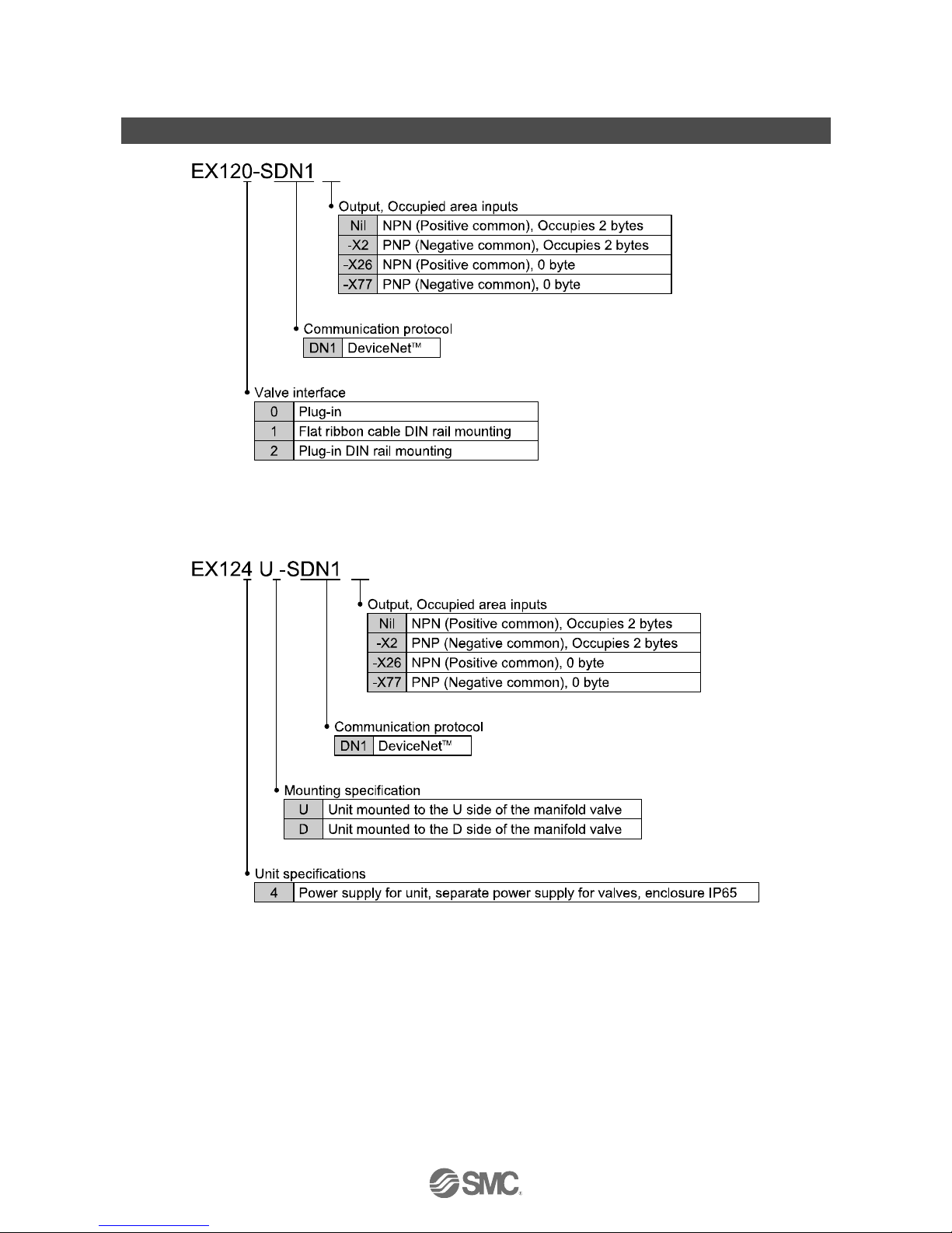
EX120-SDN1(-X2/-X26/-X77)
EX121-SDN1(-X2/-X26/-X77)
EX122-SDN1(-X2/-X26/-X77)
EX124U/D-SDN1(-X2/-X26/-X77)
Page 2

-1-
No.EX##-OME0015-C
Contents
Safety Instructions 2
How to Order 7
Summary of Product elements 8
Installation and wiring 10
Installation 10
Wiring 10
LED indication and settings 13
DeviceNetTM Objects 21
Troubleshooting and Maintenance 30
Specifications 40
Specifications 40
Dimensions 42
Accessories 45
Page 3
-2-
No.EX##-OME0015-C
Safety Instructions
These safety instructions are intended to prevent hazardous situations and/or equipment damage.
These instructions indicate the level of potential hazard with the labels of "Caution", "Warning" or
"Danger". They are all important notes for safety and must be followed in addition to International
standards (ISO/IEC)
∗
1
)
and other safety regulations.
∗1) ISO 4414: Pneumatic fluid power -- General rules relating to systems.
ISO 4413: Hydraulic fluid power -- General rules relating to systems.
IEC 60204-1: Safety of machinery -- Electrical equipment of machines. (Part 1: General requirements)
ISO 10218-1992: Manipulating industrial robots -Safety.
etc.
Caution :
CAUTION indicates a hazard with a low level of risk which, if not avoided,
could result in minor or moderate injury.
Warning :
WARNING indicates a hazard with a medium level of risk which, if not
avoided, could result in death or serious injury.
Danger :
DANGER indicates a hazard with a high level of risk which, if not avoided,
will result in death or serious injury.
Warning
1. The compatibility of the product is the responsibility of the person who designs the
equipment or decides its specifications.
Since the product specified here is used under various operating conditions, its compatibility with
specific equipment must be decided by the person who designs the equipment or decides its
specifications based on necessary analysis and test results. The expected performance and safety
assurance of the equipment will be the responsibility of the person who has determined its
compatibility with the product. This person should also continuously review all specifications of the
product referring to its latest catalog information, with a view to giving due consideration to any
possibility of equipment failure when configuring the equipment.
2. Only personnel with appropriate training should operate machinery and equipment.
The product specified here may become unsafe if handled incorrectly. The assembly, operation and
maintenance of machines or equipment including our products must be performed by an operator
who is appropriately trained and experienced.
3. Do not service or attempt to remove product and machinery/equipment until safety is confirmed.
1. The inspection and maintenance of machinery/equipment should only be performed after measures
to prevent falling or runaway of the driven objects have been confirmed.
2. When the product is to be removed, confirm that the safety measures as mentioned above are
implemented and the power from any appropriate source is cut, and read and understand the
specific product precautions of all relevant products carefully.
3. Before machinery/equipment is restarted, take measures to prevent unexpected operation and
malfunction.
4. Contact SMC beforehand and take special consideration of safety measures if the product is
to be used in any of the following conditions.
1. Conditions and environments outside of the given specifications, or use outdoors or in a place exposed
to direct sunlight.
2. Installation on equipment in conjunction with atomic energy, railways, air navigation, space, shipping,
vehicles, military, medical treatment, combustion and recreation, or equipment in contact with food and
beverages, emergency stop circuits, clutch and brake circuits in press applications, safety equipment or
other applications unsuitable for the standard specifications described in the product catalog.
3. An application which could have negative effects on people, property, or animals requiring special
safety analysis.
4. Use in an interlock circuit, which requires the provision of double interlock for possible failure by
using a mechanical protective function, and periodical checks to confirm proper operation.
Page 4
-3-
No.EX##-OME0015-C
Caution
The product is provided for use in manufacturing industries.
The product herein described is basically provided for peaceful use in manufacturing industries.
If considering using the product in other industries, consult SMC beforehand and exchange
specifications or a contract if necessary.
If anything is unclear, contact your nearest sales branch.
Limited warranty and Disclaimer/Compliance Requirements
The product used is subject to the following "Limited warranty and Disclaimer" and "Compliance
Requirements".
Read and accept them before using the product.
Limited warranty and Disclaimer
1. The warranty period of the product is 1 year in service or 1.5 years after the product is delivered,
whichever is first.
*2)
Also, the product may have specified durability, running distance or replacement parts. Please
consult your nearest sales branch.
2. For any failure or damage reported within the warranty period which is clearly our responsibility, a
replacement product or necessary parts will be provided.
This limited warranty applies only to our product independently, and not to any other damage
incurred due to the failure of the product.
3. Prior to using SMC products, please read and understand the warranty terms and disclaimers noted
in the specified catalog for the particular products.
∗2) Vacuum pads are excluded from this 1 year warranty.
A vacuum pad is a consumable part, so it is warranted for a year after it is delivered.
Also, even within the warranty period, the wear of a product due to the use of the vacuum pad or failure due to
the deterioration of rubber material are not covered by the limited warranty.
Compliance Requirements
1. The use of SMC products with production equipment for the manufacture of weapons of mass
destruction (WMD) or any other weapon is strictly prohibited.
2. The exports of SMC products or technology from one country to another are governed by the
relevant security laws and regulation of the countries involved in the transaction. Prior to the
shipment of a SMC product to another country, assure that all local rules governing that export are
known and followed.
Page 5
-4-
No.EX##-OME0015-C
Operator
♦This operation manual is intended for those who have knowledge of machinery using pneumatic
equipment, and have sufficient knowledge of assembly, operation and maintenance of such
equipment. Only those persons are allowed to perform assembly, operation and maintenance.
♦Read and understand this operation manual carefully before assembling, operating or providing
maintenance to the product.
■Safety Instructions
Warning
■Do not disassemble, modify (including changing the printed circuit board) or repair.
An injury or failure can result.
■Do not operate the product outside of the specifications.
Do not use for flammable or harmful fluids.
Fire, malfunction, or damage to the product can result.
Verify the specifications before use.
■Do not operate in an atmosphere containing flammable or explosive gases.
Fire or an explosion can result.
This product is not designed to be explosion proof.
■If using the product in an interlocking circuit:
•Provide a double interlocking system, for example a mechanical system
•Check the product regularly for proper operation
Otherwise malfunction can result, causing an accident.
■The following instructions must be followed during maintenance:
•Turn off the power supply
•Stop the air supply, exhaust the residual pressure and verify that the air is released before performing
maintenance
Otherwise an injury can result.
Caution
■After maintenance is complete, perform appropriate functional inspections.
Stop operation if the equipment does not function properly.
Safety cannot be assured in the case of unexpected malfunction.
■Provide grounding to assure the safety and noise resistance of the Serial System.
Individual grounding should be provided close to the product with a short cable.
Page 6

-5-
No.EX##-OME0015-C
■NOTE
○Follow the instructions given below when designing, selecting and handling the product.
•The instructions on design and selection
(installation, wiring, environment, adjustment, operation,
maintenance, etc.)
described below must also be followed.
∗Product specifications
•When conformity to UL is required, the SI unit should be used with a UL1310 Class2 power supply.
•The SI unit is a
approved product only if they have a mark on the body.
•Use the specified voltage.
Otherwise failure or malfunction can result.
•Reserve a space for maintenance.
Allow sufficient space for maintenance when designing the system.
•Do not remove any nameplates or labels.
This can lead to incorrect maintenance, or misreading of the operation manual, which could cause damage or
malfunction to the product.
It may also result in non-conformity to safety standards.
•Product handling
∗Installation
•Do not drop, hit or apply excessive shock to the fieldbus system.
Otherwise damage to the product can result, causing malfunction.
•Tighten to the specified tightening torque.
If the tightening torque is exceeded the mounting screws may be broken.
IP67 protection cannot be guaranteed if the screws are not tightened to the specified torque.
•Never mount a product in a location that will be used as a foothold.
The product may be damaged if excessive force is applied by stepping or climbing onto it.
∗Wiring
•Avoid repeatedly bending or stretching the cables, or placing heavy load on them.
Repetitive bending stress or tensile stress can cause breakage of the cable.
•Wire correctly.
Incorrect wiring can break the product.
•Do not perform wiring while the power is on.
Otherwise damage to the fieldbus system and/or I/O device can result, causing malfunction.
•Do not route wires and cables together with power or high voltage cables.
Otherwise the fieldbus system and/or I/O device can malfunction due to interference of noise and surge voltage
from power and high voltage cables to the signal line.
Route the wires (piping) of the fieldbus system and/or I/O device separately from power or high voltage cables
.
•
Confirm proper insulation of wiring.
Poor insulation (interference from another circuit, poor insulation between terminals, etc.) can lead to excess
voltage or current being applied to the product, causing damage.
•Take appropriate measures against noise, such as using a noise filter, when the fieldbus system is
incorporated into equipment.
Otherwise noise can cause malfunction.
Page 7

-6-
No.EX##-OME0015-C
∗Environment
•Select the proper type of protection according to the environment of operation.
In case of IP20, avoid use in the place where water and oil scatter.
IP65 protection is achieved when the following conditions are met.
(1) The units are connected properly with fieldbus cable with M12 connector and power cable with M12 (M8) connector.
(2) Suitable mounting of each unit and manifold valve.
If using in an environment that is exposed to water splashes, please take measures such as using a cover.
If the product is to be used in an environment containing oils or chemicals such as coolant or cleaning solvent, even
for a short time, it may be adversely affected (damage, malfunction etc.).
•Do not use the product in an environment where corrosive gases or fluids could be splashed.
Otherwise damage to the product and malfunction can result.
•Do not use in an area where surges are generated.
If there is equipment which generates a large amount of surge (solenoid type lifter, high frequency induction furnace,
motor, etc.) close to the fieldbus system, this may cause deterioration or breakage of the internal circuit of the
fieldbus system. Avoid sources of surge generation and crossed lines.
•When a surge-generating load such as a relay or solenoid is driven directly, use an fieldbus system with
a built-in surge absorbing element.
Direct drive of a load generating surge voltage can damage the fieldbus system.
•The product is CE marked, but not immune to lightning strikes. Take measures against lightning strikes
in the system.
•Prevent foreign matter such as remnant of wires from entering the fieldbus system to avoid failure and malfunction.
•Mount the product in a place that is not exposed to vibration or impact.
Otherwise failure or malfunction can result.
•Do not use the product in an environment that is exposed to temperature cycle.
Heat cycles other than ordinary changes in temperature can adversely affect the inside of the product.
•Do not expose the product to direct sunlight.
If using in a location directly exposed to sunlight, shade the product from the sunlight.
Otherwise failure or malfunction can result.
•Keep within the specified ambient temperature range.
Otherwise malfunction can result.
•Do not operate close to a heat source, or in a location exposed to radiant heat.
Otherwise malfunction can result.
∗Adjustment and Operation
•Set the switches by using a sharp-pointed screwdriver etc.
It may damage set switches.
•Perform settings suitable for the operating conditions.
Incorrect setting can cause operation failure.
For details of each setting, refer to page 13 to 20 of this manual.
•Please refer to the PLC manufacturer's manual etc. for details of programming and addresses.
For the PLC protocol and programming refer to the relevant manufacturer's documentation.
∗Maintenance
•Turn off the power supply, stop the supplied air, exhaust the residual pressure and verify the release of
air before performing maintenance.
There is a risk of unexpected malfunction.
•Perform regular maintenance and inspections.
There is a risk of unexpected malfunction.
•After maintenance is complete, perform appropriate functional inspections.
Stop operation if the equipment does not function properly.
Otherwise safety is not assured due to an unexpected malfunction or incorrect operation.
•Do not use solvents such as benzene, thinner etc. to clean the each unit.
They could damage the surface of the body and erase the markings on the body.
Use a soft cloth to remove stains.
For heavy stains, use a cloth soaked with diluted neutral detergent and fully squeezed, then wipe up the stains
again with a dry cloth.
Page 8
-7-
No.EX##-OME0015-C
How to Order
Page 9
-8-
No.EX##-OME0015-C
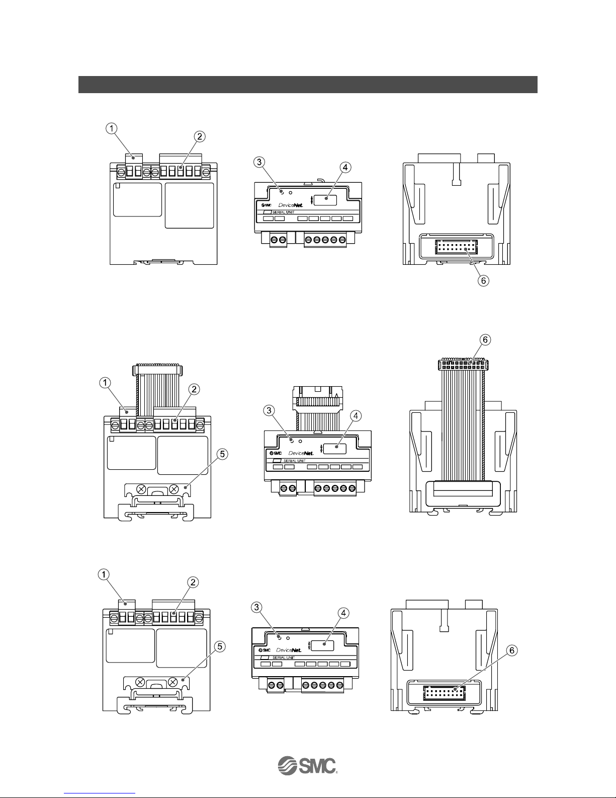
Summary of Product Parts
○EX120-SDN1(-X2/-X26/-X77)
○EX121-SDN1(-X2/-X26/-X77)
○EX122-SDN1(-X2/-X26/-X77)
Page 10
-9-
No.EX##-OME0015-C
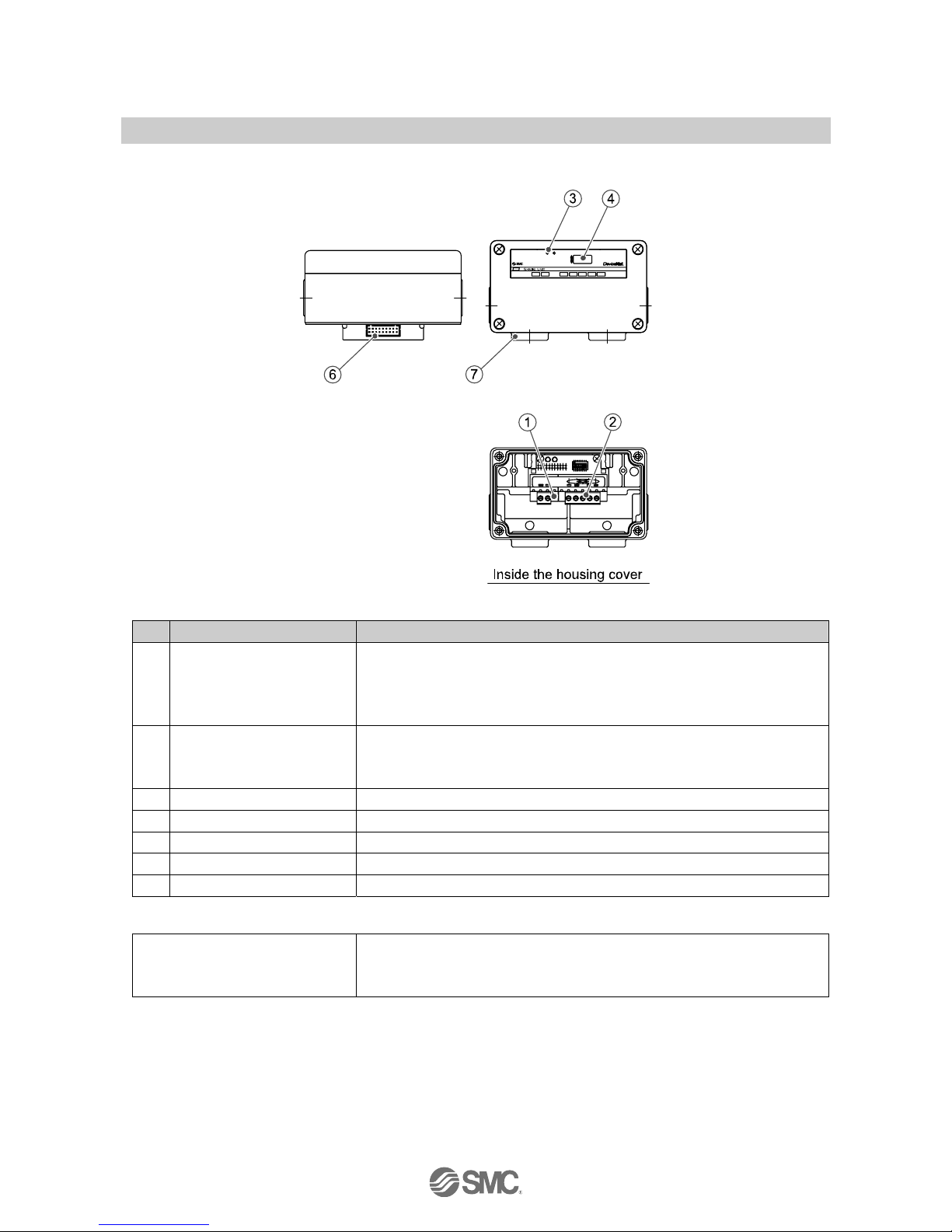
○EX124U/D-SDN1(-X2/-X26/-X77)
No. Element Description
1 Power supply connector
The power supply connector, provided as an accessory, is used to supply the
power for the solenoid valves.
∗
1
EX12∗-SDN1/-X2: Green
EX12∗-SDN1-X26/-X77: Grey
2 Communication connector
The communication connector is used to connect to the DeviceNetTM line.
∗
1
EX12∗-SDN1/-X2: Green
EX12∗-SDN1-X26/-X77: Grey
3 Display Displays the status of the unit with LEDs.
4 Switch setting For performing the address/communication speed setting etc.
5 Mounting bracket For mounting to a DIN rail.
6 Output connector The output connector is used to connect the valve manifold.
7 Conduit port (4xG1/2) Port used for wiring the EX124U/D-SDN1/-X2/-X26/-X77.
∗
1
Accessory
Round head screw (M4x10) with
spring washer
(EX124U/D-SDN1 only)
Connects the SI unit to the valve manifold. (4 pcs.)
∗1: Refer to “Wiring" on page 10 of this operation manual for applicable connectors.
∗2: Refer to “LED display and Settings” on page 13 of this operation manual for the LED display and settings.
Page 11
-10-
No.EX##-OME0015-C
Installation and wiring
■Installation
Connect the valve manifold to the SI unit when installing the SI unit.
Refer to the catalogue for the valve manifold dimensions.
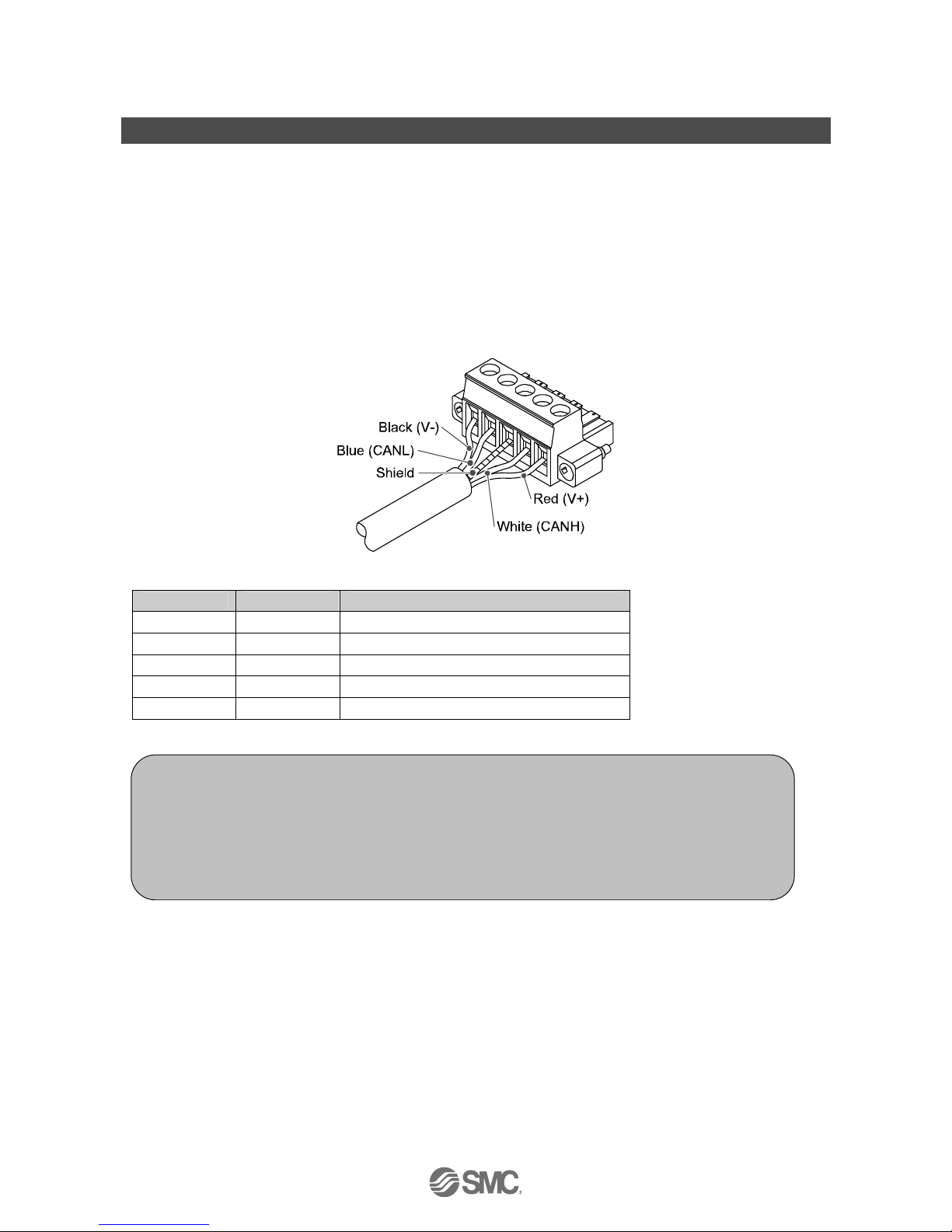
■Wiring
○Communication wiring
MSTB2, 5/5-STF-5, 08AU connectors manufactured by Phoenix Contact are attached to the SI unit for
mounting on the cable.
The connector screws should be tightened securely with a tightening torque of 0.5 to 0.6 Nm.
Communication connector
Terminal Wire colour Connection
V- Black (-) side of DeviceNetTM power supply cable
CANL Blue Low side of communication cable
FG(DRAIN)
-
Ground / Shield wire
CANH White High side of communication cable
V+ Red (+) side of DeviceNetTM power supply cable
Note
Wiring should be carried out with the power supply turned off.
Do not route the communication cable near to high voltage cables such as a power cable or high
current electrical cable.
Be sure to connect terminal resistors to both ends of the DeviceNet
TM
main cable.
The drain wire should be connected to ground at one point only in the communication network.
Grounding should only be made at one point.
Page 12
-11-
No.EX##-OME0015-C
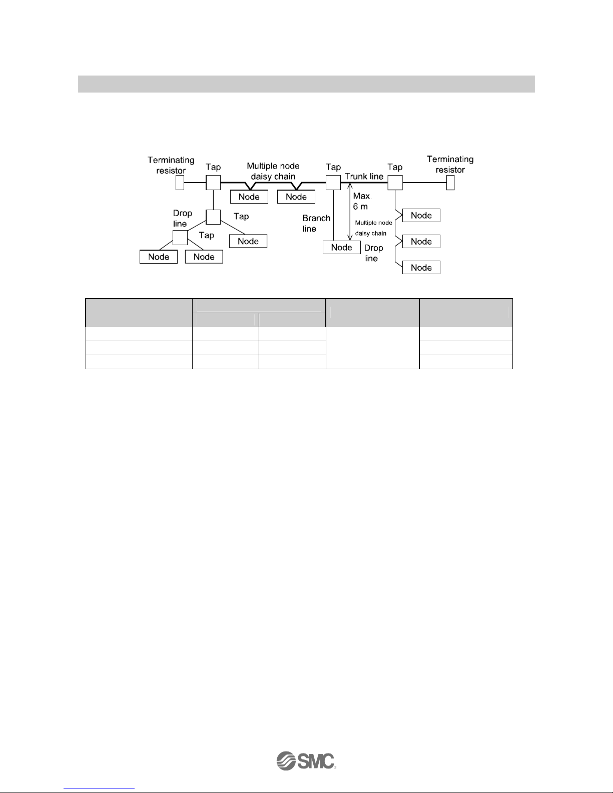
○DeviceNetTM Media Topology
A shielded twisted pair cable for DeviceNetTM should be used.
The maximum cable length depends on the communication speed and the cable type used.
<Communication speed [kbps] and maximum bus cable length>
Max. cable length for network
Communication speed
Thick cable Thin cable
Drop line length Cummulative Drop
500 kbps 100 m 100 m 39 m max.
250 kbps 250 m 100 m 78 m max.
125 kbps 500 m 100 m
6 m or less
156 m max.
○Terminating resistors
DeviceNet
TM
requires a terminating resistor to be installed at each end of the trunk.
The resistor requirements are:
•121 Ω
•1% metal film
•1/4 watt
Terminating resistors should not be installed at the end of a drop line, only at the two ends of trunk line.
Page 13
-12-
No.EX##-OME0015-C
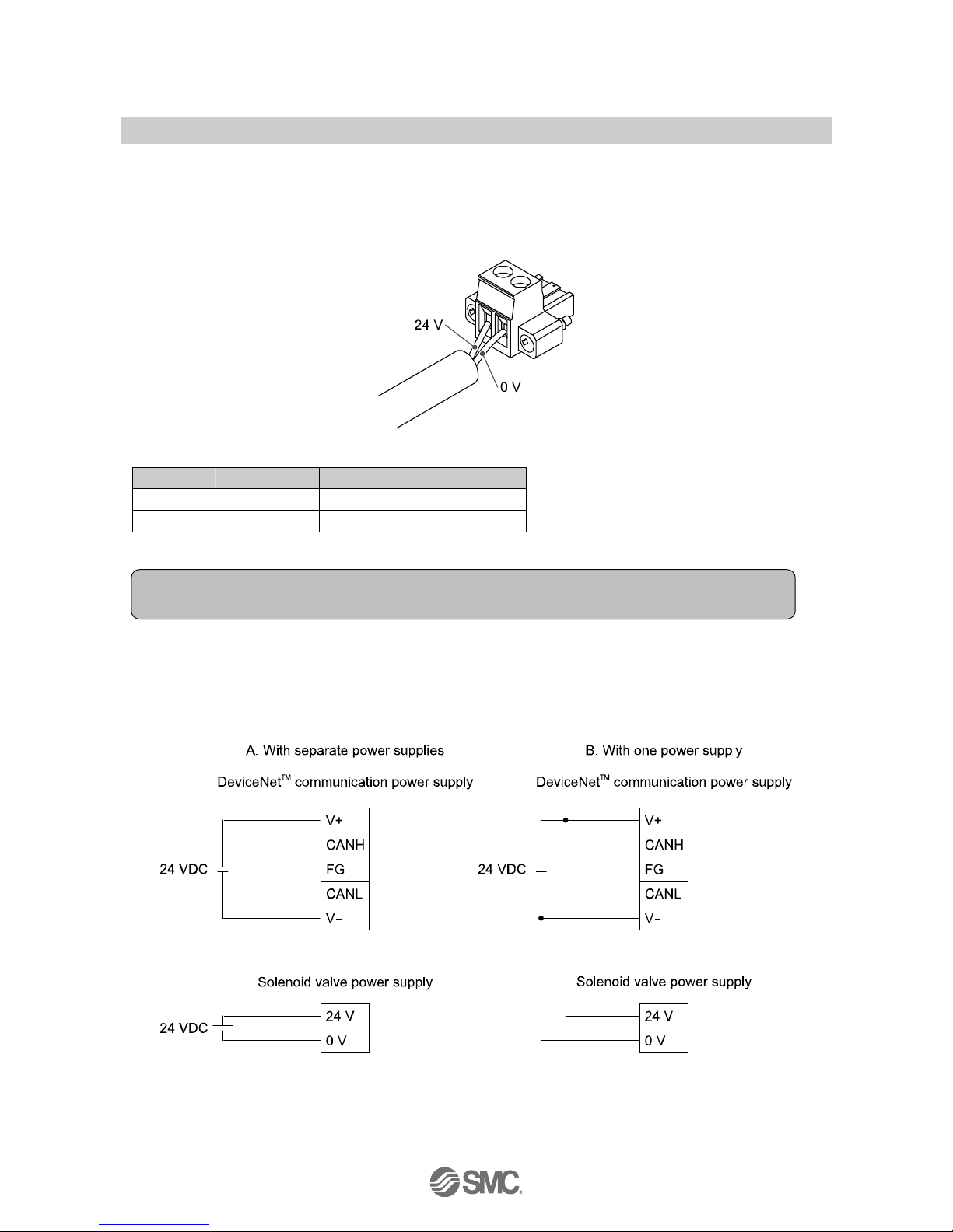
○Power supply wiring (Power supply for solenoid valve)
MSTB2, 5/2-STF-5, 08 connectors manufactured by Phoenix Contact are attached to the SI unit for mounting
on the cable.
The power supply connector for the solenoid valve is wired in the following way.
The connector screws should be tightened securely with a tightening torque of 0.5 to 0.6 Nm.
Power supply connector for solenoid valve
Terminal Wire colour Connection
24 V
−
For solenoid valve +24 V
0 V
−
For solenoid valve 0 V
Within the SI unit there are separate power supplies for the solenoid valves and DeviceNetTM
communications.
Supply 24 VDC to each of them.
Power can be supplied from a single power supply or from separate power supplies.
∗: Pay attention not to exceed the tolerance range of power supply voltage.
Note
Wiring should be carried out with the power supply turned off.
Page 14
-13-
No.EX##-OME0015-C
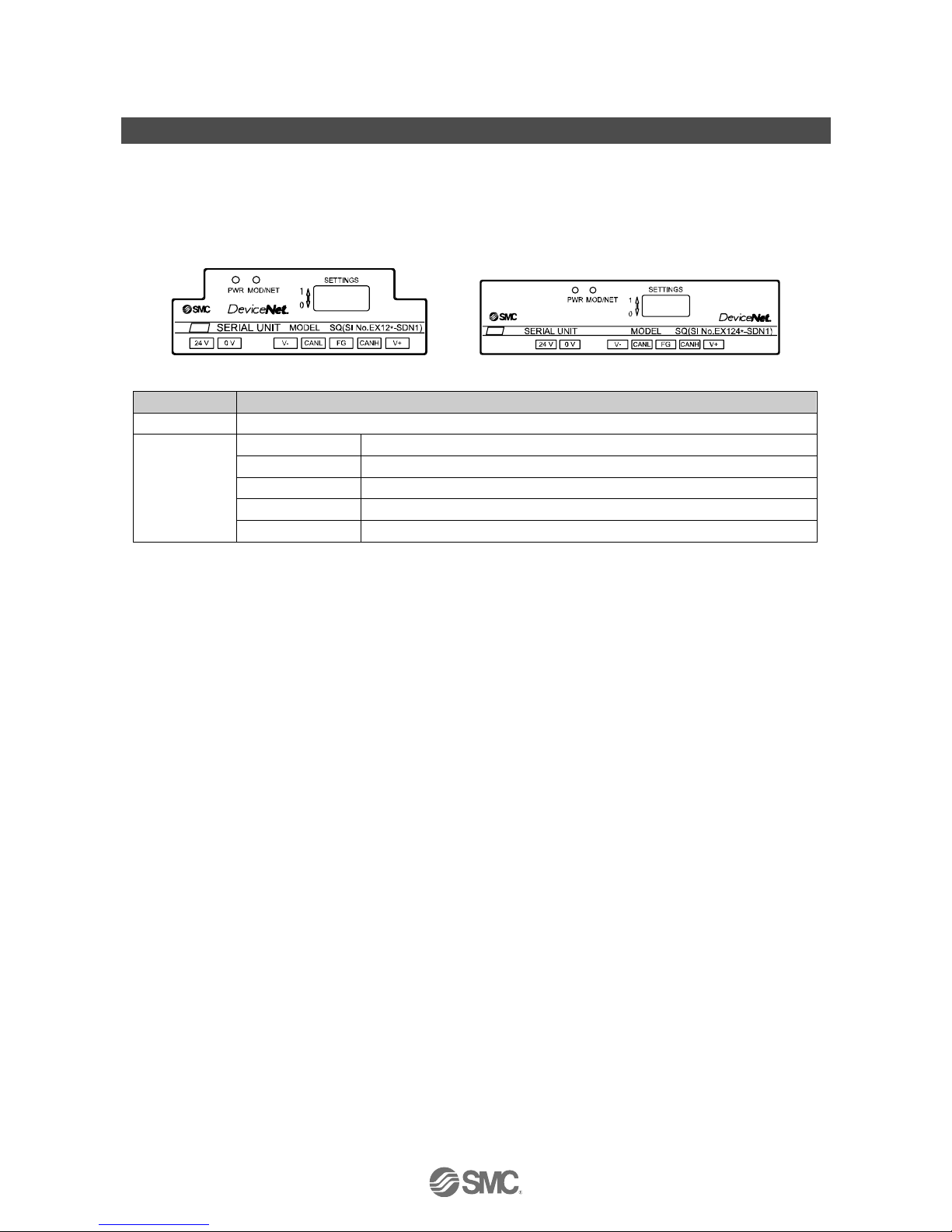
LED indication and settings
○LED display
EX120-SDN1 (-X2/-X26/-X77) EX124D-SDN1 (-X2/-X26/-X77)
EX121-SDN1 (-X2/-X26/-X77) EX124U-SDN1 (-X2/-X26/-X77)
EX122-SDN1 (-X2/-X26/-X77)
LED Display
PWR Green LED is ON when power for communication is supplied.
LED is off The unit is not on-line or the power supply for communication is off.
Green flashing Connection stand-by (on-line status)
Green On Connection established (on-line status)
Red flashing Connection time-out (recoverable communication error)
MOD/NET
Red On
MAC ID duplication error or BUS OFF error (serious communication error)
Page 15
-14-
No.EX##-OME0015-C
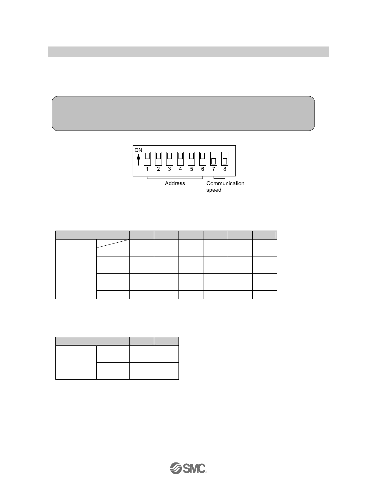
○Switch setting (EX12∗-SDN1, EX12∗-SDN1-X2)
Use the 8 way switch on the SI unit to set the node address (MAC_ID) and DeviceNetTM communication
speed.
•Address setting (switch No. 1 to 6)
Set the DeviceNet
TM
node address with a binary code between 0 and 63.
The default setting is all switches ON, so the MAC ID is set to 63.
0: OFF 1: ON
Switch No. No.1 No.2 No.3 No.4 No.5 No.6
1 2 4 8 16 32
0 0 0 0 0 0 0
1 1 0 0 0 0 0
2 0 1 0 0 0 0
: : : : : : :
62 0 1 1 1 1 1
MAC ID
63 1 1 1 1 1 1
•Communication speed setting (switches No. 7 to 8)
Set the DeviceNet
TM
communication speed with a binary code of 125 kbps or 250 kbps or 500 kbps.
The default setting of this function is both switches “OFF”, so the default value is set to 125 kbps.
0: OFF 1: ON
Switch No. No.7 No.8
125 kbps 0 0
250 kbps 1 0
500 kbps 0 1
Communication
speed
- 1 1
Note
1. Open the cover of the SI unit and use a flat blade screwdriver to set the switches.
2. Turn off the power supply while setting the switches.
3. Be sure to set the switches before use.
Page 16

-15-
No.EX##-OME0015-C
○Settings via network (EX12∗-SDN1, EX12∗-SDN1-X2)
It is possible to set the output operation via the network, when a communication error is generated, in
accordance with the procedure below.
•Output operation setting at the time of communication error
1) The instant attribute value below is set to 1 via the network
Class Instance Attribute Description Value
0: Clear setting valid
(Default)
64h
(SMC)
01h 68h (104) Hold Clear (Timeout)
1: Fault action valid
or
Class Instance attribute Description Value
0: Clear setting valid
0Fh
(Parameter)
05h 01h Hold Clear (Timeout)
1: Fault action valid
2) Set the fault action and fault values via the network.
Fault setting method is the individual setting per output with DOP object.
Fault setting Class Instance Attribute Value
Fault
action
05h
0: Fault set value
1: Output held
Fault
value
09h (DOP)
n
(Output
number+1)
06h
0: CLEAR
1: SET
∗: For details, refer to "Object mounting".
•Output condition setting when I/O connection is deleted
1) The instant attribute value below is set to 1 via the network.
Class Instance attribute Description Value
0: Follow the setting of
ID104 (Default)
64h
(SMC)
01h (01) 69h (105)
Hold Clear
(Connection Delete)
1: CLEAR
2) Set the fault action and fault values via the network.
Fault setting method is the individual setting per output with DOP object.
Fault setting Class Instance Attribute Value
Fault
action
05h
0: Fault set value
1: Output held
Fault
value
09h (DOP)
n
(Output
number+1)
06h
0: CLEAR
1: SET
∗: For details, refer to "Object mounting".
Page 17

-16-
No.EX##-OME0015-C
○Switch settings (EX12∗-SDN1-X26/-X77)
Use the 10 way switch on the SI unit to set the node address (MAC_ID) and DeviceNetTM communication
speed.
•Address setting (switches No. 1 to 6)
Set the DeviceNet
TM
node address with a binary code between 0 and 63.
The default setting is all switches ON, so the MAC ID is set to 63.
The MAC ID should be set in the range of 0 to 63.
0: OFF 1: ON
Switch No. No.1 No.2 No.3 No.4 No.5 No.6
1 2 4 8 16 32
0 0 0 0 0 0 0
1 1 0 0 0 0 0
2 0 1 0 0 0 0
: : : : : : :
62 0 1 1 1 1 1
MAC ID
63 1 1 1 1 1 1
•Communication speed setting (switches No. 7 to 8)
Set the DeviceNet
TM
communication speed with a binary code of 125 kbps or 250 kbps or 500 kbps.
The default setting of this function is both switches “OFF”, so the default value is set to 125 kbps.
0: OFF 1: ON
Switch No. No.7 No.8
125 kbps 0 0
250 kbps 1 0
500 kbps 0 1
Communication
speed
- 1 1
Note
1. Open the cover of the SI unit and use a flat blade screwdriver to set the switches.
2. Turn off the power supply while setting the switches.
3. Be sure to set the switches before use.
Page 18

-17-
No.EX##-OME0015-C
•HOLD/CLEAR setting (Switch No.9)
Set the output condition when a communication error is generated. (All outputs will be set with the same
conditions.
∗
)
The default setting of this function is both switches “OFF”, so the default value is set to CLEAR.
0: OFF 1: ON
Switch No. No.9 Function
CLEAR 0 If a communication error occurs, the output will be cleared.
HOLD/CLEAR
HOLD 1 If a communication error occurs, the output will be retained.
∗: It is possible to set the operation setting of each output via the network, when a communication error is generated.
•HW/SW setting (switch No.10)
Set the method of selecting the address, speed and output condition settings, which can be set either by
switch setting or via the network.
The default setting of this function is both switches “OFF”, so the default value is set to HW.
0: OFF 1: ON
Switch No. No.10 Function
HW 0 Address/communication speed is set using switches No. 1 to 8.
HW/SW
SW 1
Address/communication speed is set via the network.
∗
The function of the switches No.1 to 8 will become invalid.
∗: Refer to "Network setting" for the setting method via the network.
○Settings via the network (EX12∗-SDN1-X26/-X77)
It is possible to set the node address (MAC_ID), DeviceNetTM communication speed and output condition via
the network, when a communication error is generated, in accordance with the procedure below.
•Node address setting, Communication speed setting
1) Turn on (SW mode) the switch No. 10 of the 10-digit switch mounted on the SI unit.
2) Change the instance attribute value via the network as indicated below.
Class Instance Attribute Description Value
01h (01) 01h (01)
MAC ID
(Node address)
0 to 63
03h
(DeviceNet
TM
)
01h (01) 02h (02)
Baud_rate
(Communication speed)
0: 125 kbps
1: 250 kbps
2: 500 kbps
∗: The address and communication speed set in SW mode will be kept even after the DeviceNetTM communication power supply to
the SI unit is turned off.
When the power supply is applied in HW mode setting, the node address and communication speed set in SW mode is deleted
and the set value on the switch is memorized.
Page 19

-18-
No.EX##-OME0015-C
•Output condition setting during I/O connection time-out
1) The instant attribute value below is set to 1 via the network.
Class Instance Attribute Description Value
0: Switch No.9 setting valid
(Default)
64h
(SMC)
01h 68h (104)
Hold Clear
(Connection Delete)
1: Fault action valid
or
Class Instance Attribute Description Value
0: Switch No.9 setting valid
0Fh
(Parameter)
05h 01h
Hold Clear
(Connection Delete)
1: Fault action valid
2) Set the fault action and fault values via the network.
Fault setting method is the individual setting per output with DOP object.
Fault setting Class Instance Attribute Value
Fault
action
05h
0: Fault set value
1: Output held
Fault
value
09h
(DOP) n (Output number+1)
06h
0: CLEAR
1: SET
∗: For details, refer to "Object mounting".
•Output condition setting when I/O connection is deleted
1) The instant attribute value is set to 1 via the network as indicated below.
Class Instance Attribute Description Value
0: Follow the setting of ID104
(Default)
64h
(SMC)
01h (01) 69h (105)
Hold Clear
(Connection Delete)
1: CLEAR
2) Set the fault action and fault values via the network.
Fault setting method is the individual setting per output with DOP object.
Fault setting Class Instance Attribute Value
Fault
action
05h
0: Fault set value
1: Output held
Fault
value
09h (DOP)
n
(Output number+1)
06h
0: CLEAR
1: SET
∗: For details, refer to "Object mounting".
Page 20

-19-
No.EX##-OME0015-C
○I/O memory map
The SI unit occupies the memory area of 16 output points (2 bytes).
The SI unit cannot be connected to an input device, but occupies memory areas of 16 input points (2 bytes)
as a mirror function of output data.
∗
∗: Mirror function: Output data received by the SI unit will be transmitted as input data exactly as it is.
EX12∗-SDN1 and EX12∗-SDN1-X2 have this device. (EX12∗-SDN1-X26 and EX12∗-SDN1-X77 do not occupy the input area.)
Output erea mapping
Output data
offset
(Word)
offset
(Byte)
MSB
7
LSB
0
QBn+0 OUT7
……
OUT1 OUT0
QWn
QBn+1 OUT15
……
OUT9 OUT8
Input mapping (Mirror data of the output data, EX12∗-SDN1/-X2)
Input data
offset
(Word)
offset
(Byte)
MSB
7
LSB
0
IBn+0 (OUT7)
……
(OUT1) (OUT0)
IWn
IBn+1 (OUT15)
……
(OUT9) (OUT8)
Page 21

-20-
No.EX##-OME0015-C
○Output number assignment
Combinations of the output data and the valve manifold
∗: Output No. starts from 0, and will be assigned to the valves in order from the SI unit mounted side.
∗: Standard wiring on the manifold is for double-solenoid valves and output number starts A side and B side in that order as shown in
the figure a.
If you mount a single-solenoid valve on the standard wiring manifold, output number for B side valve is skipped.
∗: Custom wiring for mixed mounting single-solenoid valves and double-solenoid-valves can be specified with a Wiring Specification
Sheet. Example wiring is shown in the figure b.
∗: Bit status “0” and ”1” on a data corresponds solenoid valve status ON and OFF (0: OFF, 1: ON), and output number starts at zero
from LSB (least significant bit).
Page 22

-21-
No.EX##-OME0015-C
DeviceNetTM Objects
○DeviceNet Objects
The SI unit supports the DeviceNetTM object classes below, with pneumatic valves as the device type.
∗: Hexadecimal value is used for □□h indication.
Class code Object class
01h Identity
02h Message Router
03h DeviceNetTM
04h Assembly
05h DeviceNetTM Connection
09h Discrete Output Point
0Fh Parameter
64h SMC SI (SMC Specific)
1. Identity Object (Class ID: 01h)
1-1. Class attribute
ID Access rule Description Value
- - - -
1-2. Class common service
Service code Service name
- -
1-3. Instance attribute
ID Access rule Description Value
1 Get Vender ID 07h
2 Get Device Type
EX12∗-SDN1/-X2: 10h (16)
EX12∗-SDN1-X26/-X77: 1Bh (27)
3 Get Product Code
EX12∗-SDN1/-X2: 120h (288)
EX12∗-SDN1-X26/-X77: 4B2h (1202)
4 Get Revision Per unit
5 Get Status -
6 Get Serial Number Per unit
7 Get Product Name Valve Manifold SIU
Page 23

-22-
No.EX##-OME0015-C
1-4. Instance common service
Service code Description
05h Reset
0Eh Get_Attribute_Single
1-5. Specific service
None.
2. Message Router Object (Class ID: 02h)
2-1. Class attribute
ID Access rule Description Value
- - - -
2-2. Class common service
Service code Description
- -
2-3. Instance attribute
ID Access rule Description Value
- - - -
2-4. Instance common service
Service code Description
- -
2-5. Specific service
None.
3. DeviceNet
TM
Object (Class ID: 03h)
3-1. Class attribute
ID Access rule Description Value
1 Get revision 2
3-2. Class common service
Service code Description
0Eh Get_Attribute_Single
Page 24

-23-
No.EX##-OME0015-C
3-3. Instance attribute
ID Access rule Description Value
1 Get/Set
∗
1
MAC ID 0-63
2 Get/Set
∗
1
Baud Rate 0-2
3 Get/Set Bus Off Interrupt (BOI) 0-1
4 Get/Set Bus Off Counter 0-255
5 Get Allocation Information -
6 Get MAC ID Switch Changed 0-1
7 Get Baud Rate Switch Changed 0-1
8 Get MAC ID Switch Value 0-63
9 Get Baud Rate Switch Value 0-2
10 Set Quick Connect 0-1
∗1: EX12∗-SDN1/-X2:“Set” is unavailable. EX12∗-SDN1-X26/-X77: “Set” is available in SW mode.
3-4. Instance common service
Service code Description
0Eh Get_Attribute_Single
10h Set_Attribute_Single
3-5. Specific service
Service code Description
4Bh Allocate_Master/Slave_Connection_set
4Ch Release_Group_2_Identifier_Set
4. Assembly Object (Class ID: 04 h)
4-1. Class attribute
ID Access rule Description Value
- - - -
4-2. Class common service
Service code Service name
- -
4-3. Instance attribute
ID Access rule Description
3 Get/Set
∗
1
Data
∗1: If the instance type is input, the access rule will be Get.
Page 25

-24-
No.EX##-OME0015-C
4-4. Solenoid status assembly iInstance
(EX12∗-SDN1/-X2 supports the following functions, but EX12∗-SDN1-X26 and -X77 do not.)
ID Type Description Byte
5 Input 16 Solenoid status Points 2
The data format is shown below. (Mirror data of the output data)
Data
ID
Byte
offset
bit7 bit0
IBn+0 (OUT7) (OUT6) (OUT5) (OUT4) (OUT3) (OUT2) (OUT1) (OUT0)
5
IBn+1 (OUT15) (OUT14) (OUT13) (OUT12) (OUT11) (OUT10) (OUT9) (OUT8)
4-5. Solenoid output assembly instance
ID Type Description Byte
35 Output 16 Solenoid output points 2
The data format is shown below.
Data
ID
Byte
offset
bit7 bit0
+0 OUT7 OUT6 OUT5 OUT4 OUT3 OUT2 OUT1 OUT0
35
+1 OUT15 OUT14 OUT13 OUT12 OUT11 OUT10 OUT9 OUT8
4-6. Instance common service
Service code Description
0Eh Get_Attribute_Single
10h Set_Attribute_Single
4-7. Specific service
None.
Page 26

-25-
No.EX##-OME0015-C
5. DeviceNetTM Connection Object (Class ID: 05h)
5-1. Class attribute
ID Access rule Description Value
- - - -
5-2. Class common service
Service code Description
- -
5-3. Instance attribute1 (Explicit message)
ID Access rule Description Value
1 Get State -
2 Get Instance_type 00h
3 Get TransportClass_trigger 83h
4 Get DeviceNetTM_produced_connection_id -
5 Get DeviceNetTM_consumed_connection_id -
6 Get DeviceNetTM_initial_comm_characteristics 21h
7 Get Produced_connection_size FFFFh
8 Get Consumed_connection_size FFFFh
9 Get/Set Expected_packet_rate -
12 Get/Set Watchdog_timeout_action -
13 Get Produced_connection_path_length 0
14 Get Produced_connection_path None
15 Get Consumed_connection_path_length 0
16 Get Consumed_connection_path None
17 Get Production_inhibit_time 0
Page 27

-26-
No.EX##-OME0015-C
5-4. Instance attribute2 (I/O: Poll message)
ID Access rule Description Value
1 Get State -
2 Get Instance_type 01h
3 Get TransportClass_trigger 83h
4 Get DeviceNetTM_produced_connection_id -
5 Get DeviceNetTM_consumed_connection_id -
6 Get DeviceNetTM_initial_comm_characteristics 01h
7 Get Produced_connection_size
02h: EX12∗-SDN1/-X2
00h: EX12∗-SDN1-X26/-X77
8 Get Consumed_connection_size 02h
9 Get/Set Expected_packet_rate -
12 Get/Set Watchdog_timeout_action -
13 Get Produced_connection_path_length
6: EX12∗-SDN1/-X2
0: EX12∗-SDN1-X26/-X77
14 Get Produced_connection_path
20h, 04h, 24h, 05h, 30h, 03h:
EX12∗-SDN1/-X2
None: EX12∗-SDN1-X26/-X77
15 Get Consumed_connection_path_length 6
16 Get Consumed_connection_path 20h 04h 24h 23h 30h 03h
17 Get Production_inhibit_time 0
5-5. Instance common service
Service code Description
0Eh Get_Attribute_Single
10h Set_Attribute_Single
Page 28

-27-
No.EX##-OME0015-C
6. Discrete Output Point Object (Class ID: 09h)
6-1. Class attribute
ID Access rule Description Value
- - - -
6-2. Class common service
Service code Description
- -
6-3. Instance attribute
ID Access rule Description Value
3 Get/Set Value
0: OFF
1: ON
4 Get Status -: Unused
5 Get/Set
∗
1
Fault Action
0: Fault value
1: Output held
6 Get/Set
∗
1
Fault Value
0: CLEAR
1: SET
7 Get/Set
∗
1
Idle Action
0: Idle value
1: Output held
8 Get/Set
∗
1
Idle Value
0: CLEAR
1: SET
∗1: Hold the data in EEPROM.
6-4. Instance common service
Service code Description
0Eh Get_Attribute_Single
10h Set_Attribute_Single
6-5 Specific service
None.
Page 29

-28-
No.EX##-OME0015-C
7. Parameter Object (Class ID: 0Fh)
7-1. Class attribute
ID Access rule Description Value
2 Get Max. Instance 6
8 Get Parameter Class Descriptor 1
9 Get Configuration Assembly Instance 0
7-2. Class common service
Service code Description
0Eh Get_Attribute_Single
7-3. Instance attribute 5: Hold/Clear (Timeout)
ID Access rule Description Value
1 Get Parameter Value
0: Clear setting valid (EX12∗-SDN1/-X2)
Switch No.9 setting valid (EX12∗-SDN1-X26/-X77)
1: Fault action valid
2 Get Link Path Size 6
3 Get Link Path 20h 64h 24h 01h 30h 68h
4 Get Descriptor 20h
5 Get Data Type C1h
6 Get Data Size 1
7-4. Instance attribute 6: HOLD/Clear (Delete)
ID Access rule Description Value
1 Get Parameter Value
0: Clear setting valid (EX12∗-SDN1/-X2)
Switch No.9 setting valid (EX12∗-SDN1-X26/-X77)
1: Fault action valid
2 Get Link Path Size 6
3 Get Link Path 20h 64h 24h 01h 30h 69h
4 Get Descriptor 20h
5 Get Data Type C1h
6 Get Data Size 1
∗1: This product does not have a function that monitors the valve power supply fuse.
The value is always 0.
7-5. Instance common service
Service code Service name
0Eh Get_Attribute_Single
10h Set_Attribute_Single
7-6 Specific service
None.
Page 30

-29-
No.EX##-OME0015-C
8. SMC SI Object (Class ID: 64h)
8-1. Class attribute
ID Access rule Description Value
- - - -
8-2. Class common service
Service code Service name
- -
8-3. Instance attribute
ID Access rule Description Value
104 Get Hold/Clear (Timeout)
0: Clear setting valid (EX12∗-SDN1/-X2)
Switch No.9 setting valid (EX12∗-SDN1-X26/-X77)
1: Fault action valid
105 Get Hold/Clear (Delete)
0: Follow the setting of ID104
1: Clear
∗: This product does not have a function that monitors the valve power supply fuse. The value is always 0.
8-4. Instance common service
Service code Description
0Eh Get_Attribute_Single
10h Set_Attribute_Single
8-5. Specific service
None.
Page 31

-30-
No.EX##-OME0015-C
Troubleshooting and maintenance
Troubleshooting flowchart
When any malfunction is observed, perform the following troubleshooting.
SI unit does not
operate normally
Solenoid valves not
operating correctly
SI unit MOD/NET LED
is OFF
The solenoid
valves after output
17 do not operate
Refer to fault
No.6
Refer to fault
No.7
SI unit MOD/NET LED
is flashing Green
SI unit MOD/NET LED
is ON Green
SI unit PWR LED
is OFF
SI unit MOD/NET LED
is ON Red
SI unit MOD/NET LED
is flashing Red
Check the status
of the solenoid valves
Refer to fault
No.8
Solenoid valves not
operating correctly, solenoid
valve LED is OFF
Solenoid valves not
operating correctly, solenoid
valve LED is ON
Yes
No
Refer to fault
No.5
Refer to fault
No.4
Refer to fault
No.3
Refer to fault
No.2
Refer to fault
No.1
Page 32

-31-
No.EX##-OME0015-C
Troubleshooting table
Fault No.1
Problem Possible cause Investigation method Countermeasures
Re-wire the power supply
cable. (Replace the cable if it
is damaged).
Incorrect wiring of
the power supply
for DeviceNet
TM
communication
Check the power supply cable connections and
check for broken wires.
Correct the wiring of the
power supply cable.
SI unit PWR
LED is OFF
Failure of the
power supply for
DeviceNet
TM
communication
Check the supply voltage of the DeviceNet
TM
power supply.
Supply 11 to 25 VDC to the
DeviceNet
TM
power supply.
Fault No.2
Problem Possible cause Investigation method Countermeasures
Re-wire the DeviceNetTM
cable. (Replace the cable if it
is damaged).
Incorrect wiring of
the DeviceNet
TM
cable
Check the DeviceNetTM cable connections and
check for broken wires.
Correct the wiring of the
DeviceNet
TM
cable.
SI unit
MOD/NET LED
is OFF
Failure of the
power supply for
the DeviceNet
TM
master station
Check the wiring of the power supply for the
DeviceNet
TM
master station.
Check the power supply for
the DeviceNet
TM
master
station.
Page 33

-32-
No.EX##-OME0015-C
Fault No.3
Problem Possible cause Investigation method Countermeasures
MAC ID
duplication error
Check that there is no MAC ID duplication
between the master and slave.
Correct the MAC ID settings.
Check that the length of the communication
cable is suitable for the communication speed,
check for terminators at both ends, and check
that the special cable for DeviceNet
TM
is used.
Correct the wiring and
settings.
Check that there is no equipment or high
voltage cables which generates noise around
the communication and power supply cables.
Separate the communication
and power supply cables
away from noise sources.
Check the DeviceNetTM cable connections and
check for broken wires.
Confirm that repeated bending stresses or
pulling forces are not applied to the cable which
may cause broken wire.
Correct the connection of the
DeviceNet
TM
cable.
BUS OFF error
Confirm that the SI unit communication speed
setting and the communication speed settings
of the master and slave are the same.
Correct the communication
speed settings.
SI unit
MOD/NET LED
is ON Red
Failure of the
communication
device
-
Replace the SI unit.
Fault No.4
Problem Possible cause Investigation method Countermeasures
Check that the length of the communication
cable is suitable for the communication speed,
check for terminators at both ends, and check
that the special cable for DeviceNet
TM
is used.
Correct the wiring and
settings.
Check that there is no equipment or high
voltage cables which generates noise around
the communication and power supply cables.
Separate the communication
and power supply cables
away from noise sources.
Check the DeviceNetTM cable connections and
check for broken wires.
Confirm that repeated bending stresses or
pulling forces are not applied to the cable which
may cause broken wire.
Correct the connection of the
DeviceNet
TM
cable.
SI unit
MOD/NET LED
flashes Red
I/O connection
timeout
Confirm that power is supplied to the master
station.
Supply power to the master
station correctly.
Page 34

-33-
No.EX##-OME0015-C
Fault No. 5
Problem Possible cause Investigation method Countermeasures
Re-wire the DeviceNetTM
cable. (Replace the cable if it
is damaged).
Incorrect wiring of
the power supply
for DeviceNet
TM
communication
Check the DeviceNet
TM
cable connections and
check for broken wires.
Rectify the wiring of the
DeviceNet
TM
cable.
SI unit
MOD/NET LED
flashes Green
I/O connection
stand-by (off-line
status)
If the network is using a scan list, check that the
slave is registered correctly into the scan list.
Correct the setting of the
scan list.
Fault No. 6
Problem Possible cause Investigation method Countermeasures
The solenoid
valves after
output 17 do
not operate
The total number
of solenoid valve
outputs connected
has exceeded the
max. allowed
Check that the total number of outputs
connected to the SI unit is 16 or less.
Make corrections so that the
total number of outputs is 16
or less.
Note when single solenoid
valves are mounted onto a
double wiring specified
manifold.
Fault No. 7
Problem Possible cause Investigation method Countermeasures
Poor connection
between SI unit
and valve manifold
Check if there are any loose screws making
the connection between the SI unit and the
Valve manifold.
Tighten the screws while
holding the SI unit and the
solenoid valve manifold so
that there is no gap between
them. Tighten the screws to
the specified tightening
torque.
Polarity of the
solenoid valve and
the SI unit output
are not compatible
Check that the solenoid valve polarity
specification and output polarity of the SI unit
are compatible.
Use a solenoid valve polarity
compatible with the output
polarity of the SI unit.
Solenoid
valves do not
operate
correctly,
solenoid valve
LED is OFF
Solenoid valve
failure
Refer to the troubleshooting of the solenoid
valve.
Refer to the troubleshooting
of the solenoid valve.
Fault No. 8
Problem Possible cause Investigation method Countermeasures
Solenoid
valves do not
operate
correctly,
solenoid valve
LED is ON.
Solenoid valve
failure
Refer to the troubleshooting of the solenoid
valve.
Refer to the troubleshooting
of the solenoid valve.
Page 35

-34-
No.EX##-OME0015-C
<Precautions for replacement of SI unit>
1. Be sure to turn the power OFF before replacing the SI unit.
Otherwise injury or SI unit malfunction can result.
2. Check the wiring before supplying power.
Otherwise damage to the SI unit can result in some wiring conditions, causing breakdown or malfunction.
3. The screws should be tightened to the specified torque.
4. Check the seal is not caught or left unmounted.
Otherwise, the enclosure conditions will not be satisfied (for EX124 Series).
○How to replace the EX120 Series SI unit
•Removal
1. Lift the clip at the bottom of the SI unit with a flat blade screw driver.
By lifting the clip, the hook will be removed from the manifold, and this releases the SI unit.
2. Slide the SI unit upwards with the clip pulled.
Page 36

-35-
No.EX##-OME0015-C
3. This releases the lock. Pull the SI unit slowly and remove from the manifold.
Page 37

-36-
No.EX##-OME0015-C
•Mounting
1. Align the raised part on the manifold side at the bottom of the SI unit with the groove of the manifold, and
press it in evenly.
2. Confirm that the SI unit and manifold are securely locked together, and slide the SI unit downwards.
Page 38

-37-
No.EX##-OME0015-C
○How to replace the EX121/122 Series SI unit
•Removal
1. Loosen the mounting bracket screw.
2. Remove the SI unit by unhooking claw 2 then claw 1.
•Mounting
1. Hook claw 1 to the upper side of the DIN rail and claw 2 to the lower side.
2. Tighten the mounting bracket screw, and fix the SI unit to the DIN rail. (Tightening torque: 0.6 Nm)
Page 39

-38-
No.EX##-OME0015-C
4×M4
4×M4
Power
supply
connector
○How to replace the EX124 Series SI unit
•Removal
1. Remove the cover from the SI unit, by removing the screws (4xM4) which hold the cover.
2. Disconnect the wiring from the SI unit, and remove the SI unit from the manifold.
Disconnect the wiring to the SI unit.
(Communication connector and power supply connector)
Remove the screws (4xM4) which secure the SI unit to the manifold.
Communicati
onconnector
Page 40

-39-
No.EX##-OME0015-C
Pulling
direction
Cable with
connector
Board
3. Remove the manifold wiring from the SI unit.
Pull out the cable with connector (manifold wiring) from the manifold while holding the board of the SI
unit.
•Mounting
1. Connect the manifold wiring to the SI unit. (Follow the procedure of step 3 in reverse.)
•Ensure the cable (manifold wiring) does not get caught between the SI unit and the manifold.
Otherwise damage to the unit can result due to cable breakage, causing breakdown or malfunction.
•Tighten the screws diagonally so that the SI unit is securely fitted. (Tightening torque: 0.6 Nm)
2. Mount the SI unit to the manifold, then mount the communication connector and power supply connector.
3. Mount the cover to the SI unit after setting the switches.
Tighten the screws diagonally so that the cover unit is securely fitted. (Tightening torque: 0.6 Nm)
Page 41

-40-
No.EX##-OME0015-C
Specifications
■Specifications
General specification
Item Specifications
Ambient temperature
0 to +55
o
C (when 8 valves are ON at the same time)
0 to +50
o
C (when 16 valves are ON at the same time)
Ambient humidity 35 to 85%RH (No condensate)
Ambient temperature for
storage
−20 to +60
o
C
Withstand voltage 1000 VAC applied for 1 minute
Insulation resistance 500 VDC, 2 MΩ or more
Operating atmosphere No corrosive gas
Pollution degree Pollution degree 3 ∗
Enclosure
EX120/121/122-SDN1 (-X2/-X26/-X77): IP20
EX124U/D-SDN1 (-X2/-X26/-X77): IP65
Standard CE marking, RoHS
Weight
EX120-SDN1 (-X2/-X26/-X77): 110 g or less
EX121-SDN1 (-X2/-X26/-X77): 140 g or less
EX122-SDN1 (-X2/-X26/-X77): 130 g or less
EX124U/D-SDN1 (-X2/-X26/-X77): 240 g or less
∗: EX120/121/122-SDN1(-X2/-X26/-X77) are IP20 rated.
When operating this product in a pollution degree 3 environment,mount it onto an IP54 rate orhighercontroller board etc.
Electric specifications
Item Specifications
Power supply for
DeviceNet
TM
communication
11 to 25 VDC
0.1 A or less
Power supply voltage
range and current
consumption
Solenoid valve power
supply
24 VDC+10%/-5%
1.5 A or less, according to the solenoid valve station
specification
Output type
(Valve common polarity)
EX12-SDN1/-X26: NPN
(Positive common)
EX12-SDN1-X2/-X77: PNP
(Negative common)
Number of outputs 16 outputs
Connected load
Solenoid valve with surge voltage suppressor of 24 VDC
and 1.5 W or less (manufactured by SMC)
Output setting at the time
of communication error
EX12∗-SDN1/-X2: CLEAR
EX12∗-SDN1-X26/-X77: HOLD/CLEAR (Switch setting)
Insulation type Photo-coupler insulation type
Solenoid valve
specification
Residual voltage 0.4 VDC or less
Page 42

-41-
No.EX##-OME0015-C
Communication specification
Item Specifications
Protocol
DeviceNet
TM
Volume1 (Edition 2.1)
Volume3 (Edition 1.0)
Slave type Group2 Only Server
Device type
EX12∗-SDN1/-X2: 16
EX12∗-SDN1-X26/-X77: 27
Product code
EX12∗-SDN1/-X2: 288
EX12∗-SDN1-X26/-X77: 1202
Vender ID 7h (SMC Corp.)
Applicable message
Duplicate MAC ID Check Message
Unconnected Explicit Message
Explicit Message
Poll I/O Message (Predefined M/S connection set)
Node address setting range 0 to 63
Communication speed 125 kbps/250 kbps/500 kbps
Setting file: EDS file
(Please download from SMC website)
EX12∗-SDN1/-X2 : ex12#-sdn1_22_v□.eds
EX12∗-SDN1-X26/-X77 : ex12#-sdn1_02_v□.eds
Occupied area
(Number inputs/Outputs)
EX12∗-SDN1/-X2: 16/16
EX12∗-SDN1-X26/-X77: 0/16
Compatible valve series
EX120-SDN1(-X2/-X26/-X77)
SV1000, SV2000, SV3000, SV4000
VQ1000, VQ2000
SY3000, SY5000 (Connector connecting manifold)
EX121-SDN1(-X2/-X26/-X77) SY3000, SY5000
EX122-SDN1(-X2/-X26/-X77) SY3000, SY5000
EX124U/D-SDN1(-X2/-X26/-X77) VQ2000, VQ4000, VQ5000
Page 43

-42-
No.EX##-OME0015-C
■Dimensions
○EX120-SDN1(-X2/-X26/-X77)
○EX121-SDN1(-X2/-X26/-X77)
Page 44

-43-
No.EX##-OME0015-C
○EX122-SDN1(-X2/-X26/-X77)
○EX124D-SDN1(-X2/-X26/-X77)
Page 45

-44-
No.EX##-OME0015-C
○EX124U-SDN1(-X2/-X26/-X77)
Page 46

-45-
No.EX##-OME0015-C
■Accesary
○Waterproof cap
Use for unused conduit port (G1/2) when using EX124 Series.
Part No: AXT100-B04A
Page 47

No.EX##-OME0015-C
Revision history
A: All revised contents
B: Revision
C: Revision
Note: Specifications are subject to change without prior notice and any obligation on the part of the manufacturer.
DeviceNet
TM
is a trademark of ODVA.
© 2012 SMC Corporation All Rights Reserved
 Loading...